EP2573475A2 - Als Induktionsgerät ausgebildetes lufttechnisches Gerät sowie Verfahren zum Betreiben des Geräts - Google Patents
Als Induktionsgerät ausgebildetes lufttechnisches Gerät sowie Verfahren zum Betreiben des Geräts Download PDFInfo
- Publication number
- EP2573475A2 EP2573475A2 EP12005778A EP12005778A EP2573475A2 EP 2573475 A2 EP2573475 A2 EP 2573475A2 EP 12005778 A EP12005778 A EP 12005778A EP 12005778 A EP12005778 A EP 12005778A EP 2573475 A2 EP2573475 A2 EP 2573475A2
- Authority
- EP
- European Patent Office
- Prior art keywords
- induction
- air
- nozzles
- group
- nozzle
- Prior art date
- Legal status (The legal status is an assumption and is not a legal conclusion. Google has not performed a legal analysis and makes no representation as to the accuracy of the status listed.)
- Granted
Links
Images



Classifications
-
- F—MECHANICAL ENGINEERING; LIGHTING; HEATING; WEAPONS; BLASTING
- F24—HEATING; RANGES; VENTILATING
- F24F—AIR-CONDITIONING; AIR-HUMIDIFICATION; VENTILATION; USE OF AIR CURRENTS FOR SCREENING
- F24F1/00—Room units for air-conditioning, e.g. separate or self-contained units or units receiving primary air from a central station
- F24F1/01—Room units for air-conditioning, e.g. separate or self-contained units or units receiving primary air from a central station in which secondary air is induced by injector action of the primary air
-
- F—MECHANICAL ENGINEERING; LIGHTING; HEATING; WEAPONS; BLASTING
- F24—HEATING; RANGES; VENTILATING
- F24F—AIR-CONDITIONING; AIR-HUMIDIFICATION; VENTILATION; USE OF AIR CURRENTS FOR SCREENING
- F24F13/00—Details common to, or for air-conditioning, air-humidification, ventilation or use of air currents for screening
- F24F13/26—Arrangements for air-circulation by means of induction, e.g. by fluid coupling or thermal effect
-
- F—MECHANICAL ENGINEERING; LIGHTING; HEATING; WEAPONS; BLASTING
- F24—HEATING; RANGES; VENTILATING
- F24F—AIR-CONDITIONING; AIR-HUMIDIFICATION; VENTILATION; USE OF AIR CURRENTS FOR SCREENING
- F24F13/00—Details common to, or for air-conditioning, air-humidification, ventilation or use of air currents for screening
- F24F13/02—Ducting arrangements
- F24F13/06—Outlets for directing or distributing air into rooms or spaces, e.g. ceiling air diffuser
- F24F2013/0612—Induction nozzles without swirl means
Definitions
- the invention relates to an induction device designed as a ventilation device, with several, with air, in particular with primary air, operated induction nozzles.
- An induction device of the type mentioned is known.
- an induction effect is produced, which causes air, in particular secondary air, to be sucked in and mixed with the air blown out of the induction nozzles.
- This mixed air is then preferably the ventilation of a room of a building or the like. If the air sucked in by the induction effect flows through a heat exchanger and / or the mixed air flows through a heat exchanger, the room can be air-conditioned.
- the known induction device has a plurality of juxtaposed induction nozzles, each of which emits an induction air jet, so that a correspondingly wide zone unfolds an induction effect by the juxtaposition of the induction nozzles, with the result that, for example, a heat exchanger over its entire width for the passage of secondary air can be used.
- the known induction device to induction nozzles with a relatively large cross section. The result is a relatively high sound pressure level during operation of the known ventilation device.
- the invention has for its object to provide an induction device of the type mentioned, which works relatively quiet with high induction power.
- the induction nozzles are grouped and / or arranged in such a way that from the induction nozzles of one group or each of the groups emerging air jets merge to or in each case to only one induction air jet.
- the mentioned common induction air jet is composed of the air jets of a plurality of induction nozzles, these induction nozzles being arranged in a group.
- several groups of each combined induction nozzles are present.
- the individual induction nozzles of the device according to the invention are preferably made smaller, that is, with a smaller cross-section.
- the merged induction air jet of a group of induction nozzles according to the invention provides the same or at least approximately the same induction effect as the known, larger-diameter induction nozzle of the known device.
- the sound pressure level of the grouped induction nozzles is lower, that therefore an induction device is created compared to the known devices with correspondingly comparable parameters of the delivered air volume, especially primary air quantity, and at the same pressure of the air, the Nozzle applied, in particular primary air pressure, the same or about the same induction effect achieved at a lower sound pressure level.
- the induction nozzles of each group have a smaller distance from each other than the distance between adjacent groups.
- the air jets of the induction jets of each group unite in each case only one induction air jet, but the induction air jets of the individual groups preferably do not combine.
- each of the groups has at least two, in particular two to five, preferably three induction nozzles. In this respect, two to five groups, preferably threes are formed.
- the induction nozzles of each group are arranged spatially relative to one another.
- the induction nozzles of each group may lie on a straight line, being positioned from the direction such that the air jets may merge into the induction air jet or, as mentioned above, being arranged spatially relative to each other, for example at three Induction nozzles a triangular arrangement is provided, with the result that then also the fusion of the air jets takes place.
- the latter is also possible if the induction nozzles of a group blow in the same direction or it is alternatively provided that the Ausblaslegien the induction nozzles of a group are different, in particular converge to each other, yet a spatial arrangement of the induction nozzles can be provided.
- the merger point is thus once as far away from the outlet openings of the associated induction nozzles as far as the distance from adjacent, associated induction nozzles, wherein the distance D extends from the center of an induction nozzle to the center of an adjacent induction nozzle.
- a development of the invention provides that the exit angle of the air jet of each induction nozzle of the same group is in the range of 10 ° to 30 °, in particular has a size of 20 °.
- At least one induction nozzle of the induction nozzles of at least one group can be opened or closed.
- the arrangement is preferably such that not all induction nozzles of a group can be opened or closed, but only one or more, but not all, so that a certain induction effect remains and the induction air jet is generated by fusion, that is, at least two induction nozzles of the same Group stay open.
- the mentioned "opening or closing" can also be carried out with intermediate values, ie only a partial opening or partial closing.
- a development of the invention provides that the induction nozzle to be opened or closed is located farther away from a heat exchanger of the induction device than the other induction nozzles of the same group.
- the "other" induction nozzles of the same group mean those that can not be opened or closed. Since - as mentioned - the ventilation device has a heat exchanger which performs a temperature of the sucked by induction air, in particular secondary air, the removal of an induction nozzle to the heat exchanger influence on the heating or cooling result. In this respect, it is advantageous if an induction nozzle to be closed further away from the heat exchanger, since then the other induction nozzles of this group are closer to the heat exchanger accordingly.
- the opening or closing of the induction nozzle takes place by means of a slide, which cooperates with the outlet opening of the induction nozzle.
- This slider can be adjusted automatically, for example by means of a slider drive. Additionally or alternatively, a manual adjustment of the slider is possible.
- the slide covers with a control edge more or less the cross section of the outlet opening or releases it or closes it completely.
- the displacement direction of the slide extends transversely, in particular at right angles, to the outflow direction of the air from the induction nozzle.
- the invention further relates to a method for operating an induction device designed as a ventilation device, in particular as described above, with a plurality of air, in particular with primary air, operated induction nozzles from which air jets emerge, wherein the air jets of several, one group or one group forming induction nozzles are formed such that they merge with each other or to only one induction air jet.
- the preferably uniform and / or preferably equal-sized air jets of induction nozzles of the same group are formed such that the induction effect of the formed Indu Vietnameses Kunststoffstrahls is as large or nearly as large as the induction effect of a fictitious, single, cross-sectional size, a Fiunktluftstrahl Ausblasenden induction nozzle at the same volume flow of induction air jet of the induction nozzles of this group and fictitious air jet and at the same air pressure, in particular primary air pressure, with which the induction nozzles and the fictitious induction nozzle are supplied.
- the preferably uniform and / or preferably equal-sized air jets of induction nozzles of the same group are formed such that the sound pressure level of these induction - when flowing through a certain amount of air delivered, in particular primary air quantity - is smaller or equal to the same size as the sound pressure level of a fictitious, single, cross-sectional sized, a fictitious air blowout induction nozzle at the same amount of delivered air, in particular primary air quantity, and at the same volume flow of induction air jet of the induction nozzles of this group and fictitious air jet and / or the same induction effect of the induction air jet and fictitious air jet.
- FIG. 1 shows - in longitudinal section - an air-technical device 1, which is designed as induction device 2, preferably as a ceiling-mounted device 3. It serves to ventilate and / or air-condition a room of a building or the like.
- the device 1 has a housing 4, in which a downwardly open, so there is not covered by the housing 4 heat exchanger 5 is disposed horizontally. Further, in the housing 4, an air distribution box 6 is arranged, which is air-technically connected to a primary air connection piece 7. Opposite the air distribution box 6 is an air outlet 8. Below the heat exchanger 5 is an air inlet 9.
- the heat exchanger 5 has medium connection pieces 10 and 11 in order to be able to conduct a medium, for example warm water or cold water, through the heat exchanger 5.
- the heat exchanger 5 has a plurality of heat exchanger fins 12, of which - for the sake of simplicity - lying in a small zone heat exchanger fins 12 are excellent, the remaining heat exchanger fins 12 are indicated only in a box.
- FIG. 2 illustrates the ventilation device 1 in view from the rear. It can be seen that the air distribution box 6 extends over the entire width of the device and that the primary air connection piece 7 is preferably designed as a round pipe socket.
- the heat exchanger 5 can in FIG. 2 Recognize heat exchange tubes 13 which are connected to the medium connection pieces 10 and 11.
- FIG. 3 shows that the air outlet 8 extends substantially over the entire width of the ventilation device 1 and can be provided with air guide fins 14.
- the air distribution box 6 has a wall 15 which lies opposite to the air outlet 8 and arranged on the induction nozzles 16, in particular are formed.
- air in particular primary air, which is preferably supplied by an air center of the building or the like via an air distribution network, is introduced into the air distribution box 6 via the primary air connecting piece 7.
- This air hereinafter referred to as primary air, exits from the induction nozzles 16 and produces an induction effect which causes secondary air, in particular room air, to be sucked in through the air inlet 9, which passes through the heat exchanger 5 and is heat-treated and then into a mixing space 17 inside the housing 4 passes, where it is mixed with the leaked from the primary air nozzles 16 primary air, wherein the thus formed mixed air is blown through the air outlet 8 into the room.
- the arrow 18 indicates the primary air, the Arrow 19, the secondary air and the arrow 20, the mixed air or supply air.
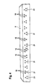
- FIG. 4 illustrates that the aforementioned induction nozzles 16 are grouped formed on the air distribution box 6. In each case three, lying on an imaginary triangle primary air nozzles 16 form a group 21. A plurality of groups, in the embodiment thirteen groups 12 are spaced over the length of Lucasverteilkastens 6 to each other, wherein the distance of the individual groups 21 from each other is greater than the distance Induction nozzles 16 within each group 21 from each other.
- the arrangement of the induction nozzles 16 of each group 21 is spatially provided, that is, they are not on a straight line, but they are arranged on an imaginary triangle, with adjacent groups in the triangle configuration alternate by either an induction nozzle 16 above and two induction nozzles 16 at the bottom or two induction nozzles 16 at the top and one induction nozzle 16 at the bottom.
- the invention is of course not on the concrete group of three of the induction nozzles 16 according to FIG. 4 limited, but it can of course be present more or less induction nozzles 16, which are arranged in any pattern to each other.
- FIG. 5 a scale superimposed, showing that the individual air jets 22-starting from the outlet openings 24 of the induction nozzles 16-only have a free jet length of 20 to 30 mm, wherein the individual induction nozzles 16 of the group 21 a distance of about 20 mm, in particular 18 mm, to each other exhibit. The distance of the nozzles from each other is measured from middle nozzle to middle nozzle.
- the invention assumes that, with the same total volume flow and constant admission pressure, different induction nozzle arrangements can be present, namely a few large conventional nozzles (prior art) or many smaller induction nozzles 16, as the latter is the case with the invention.
- many small nozzles are now distributed uniformly over the air distribution box 6, but grouped such that each group 21 of correspondingly small induction nozzles 16 only forms one induction air jet 23, ie their air jets 22 merge this induction air jet 23, wherein the merged induction air jet 23 unfolds about an induction effect, which corresponds to that of a larger, known nozzle.
- the sum of the flow noise of the small induction nozzles 16 of several groups 21 is less than the sum of the flow noise of the large nozzles known from the prior art, the number of which corresponds to the number of groups 21.
- An insertion loss that is to say a reduction of the radiating channel noise, is more favorable in the case of the smaller induction nozzles 16 according to the invention.
- the positive acoustic properties of the smaller, inventive induction nozzles 16 come into action and it also results in a positive induction effect corresponding to the favorable induction effect of large nozzles by the present invention
- the smaller induction nozzles 16 are grouped so that the air jets 22 emerging from them to a common Air jet, namely merge into the mentioned induction air jet 23, so that the effect of this induction air jet 23 corresponds to the effect of a jet of a large nozzle with respect to the induction.
- the geometry and arrangement of the individual induction nozzles 16 according to the invention depends on the nozzle size, the primary pressure, the volume flow and the injector length. However, if the person skilled in the art knows the procedure according to the invention, then it is possible he achieves optimal values by simple experiments. This applies in particular to the resulting from the claims 11 and 12, to be performed method. At nozzle pressures of 100 to 300 Pa, the arrangement of the nozzles, as it has from the FIG. 4 shows, namely a threesome, proven.
- the upper induction nozzles 16 can be opened or closed. Accordingly, according to FIG. 4 either an upper induction nozzle 16 per group 21 or two upper induction nozzles are closed, depending on which group is considered.
- the arrangement is preferably made such that the opening and closing takes place by means of a slide 26 ( FIG. 1 ), which is displaceable with appropriate means and in the representation of FIG. 1 takes an open position.
- the slider 26 can be moved back and forth according to double arrow 27.
- a motor device may be provided or there is a manual displacement given. If the slider 26 is pushed down, it covers the outlet openings 24 of the upper induction nozzles 16 so that no air jets 22 can emerge there.
- the lower row of the induction nozzles 16 not as in FIG. 4 once have one and once two induction nozzles 16 per group 21, but there are always at least two induction nozzles 16 present so that even with covered top row of the induction nozzles 16 can take place an air jet association.
- the induction nozzles 16 of the upper row are not completely closed, but only partially. In such a case it is then also permissible that the lower row in a group 21 only an induction nozzle 16 has.
Landscapes
- Engineering & Computer Science (AREA)
- Chemical & Material Sciences (AREA)
- Combustion & Propulsion (AREA)
- Mechanical Engineering (AREA)
- General Engineering & Computer Science (AREA)
- Jet Pumps And Other Pumps (AREA)
- Ventilation (AREA)
Abstract
Description
- Die Erfindung betrifft ein als Induktionsgerät ausgebildetes lufttechnisches Gerät, mit mehreren, mit Luft, insbesondere mit Primärluft, betriebenen Induktionsdüsen.
- Ein Induktionsgerät der eingangs genannten Art ist bekannt. Durch das Betreiben der Induktionsdüsen mit Luft wird eine Induktionswirkung erzeugt, die dazu führt, dass Luft, insbesondere Sekundärluft angesaugt und mit der aus den Induktionsdüsen ausgeblasenen Luft gemischt wird. Diese Mischluft dient dann vorzugsweise der Belüftung eines Raumes eines Gebäudes oder dergleichen. Sofern die durch die Induktionswirkung angesaugte Luft einen Wärmetauscher durchströmt und/oder die Mischluft einen Wärmetauscher durchströmt, kann eine Klimatisierung des Raumes erfolgen. Das bekannte Induktionsgerät weist mehrere, nebeneinander angeordnete Induktionsdüsen auf, die jeweils für sich einen Induktionsluftstrahl ausstoßen, sodass eine entsprechend breite Zone durch die Nebeneinanderanordnung der Induktionsdüsen eine Induktionswirkung entfaltet, mit der Folge, dass beispielsweise ein Wärmetauscher über seine gesamte Breite für den Durchtritt von Sekundärluft genutzt werden kann. Um eine gute Induktionswirkung zu erzielen, weist das bekannte Induktionsgerät Induktionsdüsen mit relativ großem Querschnitt auf. Die Folge ist ein relativ hoher Schalldruckpegel beim Betrieb des bekannten lufttechnischen Geräts.
- Der Erfindung liegt die Aufgabe zugrunde, ein Induktionsgerät der eingangs genannten Art zu schaffen, das bei hoher Induktionsleistung relativ geräuscharm arbeitet.
- Diese Aufgabe wird erfindungsgemäß dadurch gelöst, dass die Induktionsdüsen gruppiert derart ausgebildet und/oder angeordnet sind, dass aus den Induktionsdüsen einer Gruppe oder einer jeden der Gruppen austretende Luftstrahlen zu oder jeweils zu nur einem Induktionsluftstrahl verschmelzen. Mithin setzt sich der erwähnte gemeinsame Induktionsluftstrahl aus den Luftstrahlen mehrerer Induktionsdüsen zusammen, wobei diese Induktionsdüsen in einer Gruppe angeordnet sind. Vorzugsweise sind mehrere Gruppen von jeweils zusammengefassten Induktionsdüsen vorhanden.
- Gegenüber den bei dem bekannten lufttechnischen Gerät verwendeten Induktionsdüsen sind die einzelnen Induktionsdüsen des erfindungsgemäßen Geräts vorzugsweise kleiner ausgebildet, das heißt mit kleinerem Querschnitt. Der verschmolzene Induktionsluftstrahl einer Gruppe von erfindungsgemäßen Induktionsdüsen erbringt jedoch gegenüber der bekannten, querschnittsgrößeren Induktionsdüse des bekannten Geräts dieselbe oder mindestens etwa dieselbe Induktionswirkung. Dabei stellt sich jedoch heraus, dass der Schalldruckpegel der gruppierten Induktionsdüsen niedriger ist, dass also aufgrund der Erfindung ein Induktionsgerät geschaffen wird, das gegenüber den bekannten Geräten bei entsprechend vergleichbaren Parametern der geförderten Luftmenge, insbesondere Primärluftmenge, und bei gleichem Druck der Luft, die die Düsen beaufschlagt, insbesondere Primärluftdruck, dieselbe oder etwa dieselbe Induktionswirkung bei geringerem Schalldruckpegel erzielt.
- Nach einer Weiterbildung der Erfindung ist vorgesehen, dass die Induktionsdüsen jeder Gruppe einen kleineren Abstand zueinander aufweisen, als der Abstand zwischen benachbarten Gruppen. Die Luftstrahlen der Induktionsdüsen jeder Gruppe vereinigen sich zu jeweils nur einem Induktionsluftstrahl, wobei sich die Induktionsluftstrahle der einzelnen Gruppen jedoch vorzugsweise nicht vereinigen.
- Eine Weiterbildung der Erfindung sieht vor, dass jede der Gruppen mindestens zwei, insbesondere zwei bis fünf, bevorzugt drei Induktionsdüsen aufweist. Insofern werden Zweier- bis Fünfergruppen, vorzugsweise Dreiergruppen gebildet.
- Ferner ist es vorteilhaft, wenn die Induktionsdüsen jeder Gruppe räumlich zueinander angeordnet sind. Die Induktionsdüsen jeder Gruppe können auf einer Geraden liegen, wobei sie von der Richtung her derart positioniert sind, dass sich die Luftstrahlen zu dem Induktionsluftstrahl vereinigen können oder es ist - wie vorstehend erwähnt - vorgesehen, dass sie räumlich zueinander angeordnet sind, also beispielsweise bei drei Induktionsdüsen eine Dreiecksanordnung vorgesehen ist, mit der Folge, dass dann ebenfalls das Verschmelzen der Luftstrahlen erfolgt. Letzteres ist auch möglich, wenn die Induktionsdüsen einer Gruppe in dieselbe Richtung ausblasen oder es ist alternativ vorgesehen, dass die Ausblasrichtungen der Induktionsdüsen einer Gruppe unterschiedlich sind, insbesondere zueinander konvergieren, wobei dennoch eine räumliche Anordnung der Induktionsdüsen vorgesehen sein kann.
- Nach einer Weiterbildung der Erfindung ist vorgesehen, dass der Abstand von benachbarten Auslassöffnungen von Induktionsdüsen derselben Gruppe das Maß D aufweist, dass der jeweilige Abstand der Auslassöffnungen bis zu dem zugehörigen Verschmelzungspunkt der zugehörigen Luftstrahlen das Maß H aufweist, und dass die folgende Beziehung gilt:

- Der Verschmelzungspunkt liegt von den Auslassöffnungen der zugehörigen Induktionsdüsen also einmal bis fünfmal soweit entfernt wie der Abstand von benachbarten, zugehörigen Induktionsdüsen, wobei der Abstand D von Mitte einer Induktionsdüse bis zur Mitte einer benachbarten Induktionsdüse reicht.
- Eine Weiterbildung der Erfindung sieht vor, dass der Austrittswinkel des Luftstrahls jeder Induktionsdüse derselben Gruppe im Bereich von 10° bis 30° liegt, insbesondere eine Größe von 20° aufweist.
- Ferner ist es vorteilhaft, wenn zumindest eine Induktionsdüse der Induktionsdüsen mindestens einer Gruppe geöffnet beziehungsweise geschlossen werden kann. Auf diese Art und Weise lässt sich der Volumenstrom des zugehörigen, verschmolzenen Induktionsluftstrahls beeinflussen und damit auch die Größe der Induktionswirkung steuern. Die Anordnung ist vorzugsweise derart getroffen, dass nicht alle Induktionsdüsen einer Gruppe geöffnet beziehungsweise geschlossen werden können, sondern nur eine oder mehrere, jedoch nicht alle, sodass eine gewisse Induktionswirkung verbleibt und auch der Induktionsluftstrahl durch Verschmelzen erzeugt wird, das heißt, mindestens zwei Induktionsdüsen derselben Gruppe bleiben geöffnet. Das erwähnte "Öffnen beziehungsweise Verschließen" kann auch mit Zwischenwerten durchgeführt werden, also nur ein teilweises Öffnen beziehungsweise teilweises Schließen. Im letzteren Falle ist es dann auch denkbar, dass alle Induktionsdüsen einer Gruppe dementsprechend geöffnet beziehungsweise geschlossen werden können, da dann die im Volumenstrom reduzierten Luftstrahlen bei einem Teilverschließen sich dennoch zu einem Induktionsluftstrahl vereinigen. Bei einem Teilverschließen ist es auch denkbar, dass nur eine der Induktionsdüsen einer Gruppe vollständig geöffnet bleibt, da sich dessen Luftstrahl mit dem Teilluftstrahl der teilverschlossenen Induktionsdüse vereinigt.
- Eine Weiterbildung der Erfindung sieht vor, dass die zu öffnende beziehungsweise zu verschließende Induktionsdüse weiter entfernt zu einem Wärmetauscher des Induktionsgeräts liegt als die anderen Induktionsdüsen derselben Gruppe. Unter den "anderen" Induktionsdüsen derselben Gruppe sind diejenigen zu verstehen, die nicht geöffnet beziehungsweise geschlossen werden können. Da - wie erwähnt - das lufttechnische Gerät einen Wärmetauscher aufweist, der eine Temperierung der durch Induktionswirkung angesaugten Luft, insbesondere Sekundärluft, vornimmt, hat die Entfernung einer Induktionsdüse zum Wärmetauscher Einfluss auf das Heiz- beziehungsweise Kühlergebnis. Insofern ist es vorteilhaft, wenn eine zu verschließende Induktionsdüse weiter entfernt zum Wärmetauscher liegt, da dann die anderen Induktionsdüsen dieser Gruppe dem Wärmetauscher entsprechend näher liegen.
- Nach einer Weiterbildung der Erfindung ist vorgesehen, dass das Öffnen beziehungsweise Verschließen der Induktionsdüse mittels eines Schiebers erfolgt, der mit der Auslassöffnung der Induktionsdüse zusammenwirkt. Dieser Schieber kann beispielsweise mittels eines Schieberantriebs automatisch verstellt werden. Zusätzlich oder alternativ ist auch eine manuelle Verstellung des Schiebers möglich. Der Schieber deckt mit einer Steuerkante den Querschnitt der Auslassöffnung mehr oder weniger ab beziehungsweise gibt diesen frei oder verschließt ihn vollständig. Die Verschieberichtung des Schiebers verläuft quer, insbesondere rechtwinklig, zu der Ausströmrichtung der Luft aus der Induktionsdüse.
- Die Erfindung betrifft ferner ein Verfahren zum Betreiben eines als Induktionsgerät ausgebildeten lufttechnischen Geräts, insbesondere wie vorstehend beschrieben, mit mehreren, mit Luft, insbesondere mit Primärluft, betriebenen Induktionsdüsen, aus denen Luftstrahlen austreten, wobei die Luftstrahlen von mehreren, eine Gruppe oder jeweils eine Gruppe bildenden Induktionsdüsen derart ausgebildet werden, dass sie zu oder jeweils zu nur einem Induktionsluftstrahl miteinander verschmelzen.
- Vorzugweise ist bei dem Verfahren vorgesehen, dass die vorzugsweise gleichartig und/oder vorzugsweise gleichgroß ausgebildeten Luftstrahlen von Induktionsdüsen derselben Gruppe derart ausgebildet werden, dass die Induktionswirkung des gebildeten Induktionsluftstrahls ebenso groß oder nahezu ebenso groß ist wie die Induktionswirkung einer fiktiven, einzigen, querschnittsgroßen, einen Fiktivluftstrahl ausblasenden Induktionsdüse bei gleichem Volumenstrom von Induktionsluftstrahl der Induktionsdüsen dieser Gruppe und Fiktivluftstrahl und bei gleichem Luftdruck, insbesondere Primärluftdruck, mit dem die Induktionsdüsen und die fiktive Induktionsdüse versorgt werden. Vorstehend wird also ein Vergleich gezogen zwischen einer erfindungsgemäßen Gruppe von Induktionsdüsen und einer aus dem Stand der Technik bekannten Induktionsdüse, die hier als fiktive Induktionsdüse bezeichnet ist und die querschnittsgrößer ausgestaltet ist als die einzelnen Induktionsdüsen der Erfindung. Bei einem Vergleich der einer Gruppe angehörenden Induktionsdüsen der Erfindung und der fiktiven Induktionsdüse des Standes der Technik stellt sich unter Berücksichtigung der vorstehend erwähnten Parameter, wie beispielsweise Luftdruck zum Betreiben der Düsen und Volumenstrom, heraus, dass eine ebensogroße oder nahezu ebenso große Induktionswirkung bei der Erfindung wie bei dem Stand der Technik erzielt wird.
- Ferner ist es vorteilhaft, wenn die vorzugsweise gleichartig und/oder vorzugsweise gleichgroß ausgebildeten Luftstrahlen von Induktionsdüsen derselben Gruppe derart ausgebildet werden, dass der Schalldruckpegel dieser Induktionsdüsen - beim Durchströmen einer bestimmten geförderten Luftmenge, insbesondere Primärluftmenge - kleiner oder maximal gleichgroß ist, wie der Schalldruckpegel einer fiktiven, einzigen, querschnittsgroßen, einen Fiktivluftstrahl ausblasenden Induktionsdüse bei der gleichen geförderten Luftmenge, insbesondere Primärluftmenge, und bei gleichem Volumenstrom von Induktionsluftstrahl der Induktionsdüsen dieser Gruppe und Fiktivluftstrahl und/oder bei gleicher Induktionswirkung von Induktionsluftstrahl und Fiktivluftstrahl. Auch hier wird also - wie im vorstehenden Absatz - ein Vergleich der Erfindung mit dem Stand der Technik durchgeführt und die erfindungsgemäßen, im Querschnitt kleineren Induktionsdüsen, die gruppiert angeordnet sind, verglichen mit einer im Querschnitt größeren, einzigen Induktionsdüse des Standes der Technik, die einen Luftstrahl ausstößt, der hier als "Fiktivluftstrahl" bezeichnet ist. Es stellt sich heraus, dass unter Berücksichtigung vergleichbarer Parameter, wie Volumenstrom, geförderter Luftmenge und/oder Induktionswirkung der Schalldruckpegel bei der erfindungsgemäßen Ausgestaltung kleiner oder maximal gleichgroß ist, wie bei dem Stand der Technik. Insbesondere hat sich herausgestellt, dass ein niedriger Schalldruckpegel vorliegt.
- Die Zeichnungen veranschaulichen die Erfindung anhand eines Ausführungsbeispiels, und zwar zeigt:
- Figur 1
- einen Längsschnitt durch ein als Induktionsgerät ausgebildetes lufttechnisches Gerät,
- Figur 2
- eine Rückansicht auf das Gerät der
Figur 1 , - Figur 3
- eine Vorderansicht des Geräts der
Figur 1 , - Figur 4
- einen Luftverteilkasten mit daran ausgebildeten Induktionsdüsen des Geräts der
Figur 1 , und - Figur 5
- ein Strömungsbild der Induktionsdüsen gemäß
Figur 4 . - Die
Figur 1 zeigt - im Längsschnitt - ein lufttechnisches Gerät 1, das als Induktionsgerät 2, bevorzugt als Deckeneinbaugerät 3 ausgebildet ist. Es dient dazu, einen Raum eines Gebäudes oder dergleichen zu belüften und/oder klimatisieren. - Das Gerät 1 weist ein Gehäuse 4 auf, in dem ein nach unten offener, also dort nicht vom Gehäuse 4 abgedeckter Wärmetauscher 5 liegend angeordnet ist. Ferner ist in dem Gehäuse 4 ein Luftverteilkasten 6 angeordnet, der mit einem Primärluftanschlussstutzen 7 lufttechnisch verbunden ist. In Gegenüberlage zum Luftverteilkasten 6 liegt ein Luftauslass 8. Unterhalb des Wärmetauschers 5 befindet sich ein Lufteinlass 9. Der Wärmetauscher 5 weist Mediumanschlussstutzen 10 und 11 auf, um ein Medium, beispielsweise warmes Wasser oder kaltes Wasser, durch den Wärmetauscher 5 leiten zu können. Der Wärmetauscher 5 besitzt eine Vielzahl von Wärmetauschlamellen 12, von denen - der Einfachheit halber - nur in einer kleinen Zone liegende Wärmetauschlamellen 12 ausgezeichnet sind, die übrigen Wärmetauschlamellen 12 werden nur kastenartig angedeutet.
- Die
Figur 2 verdeutlicht das lufttechnische Gerät 1 in Ansicht von hinten. Es ist erkennbar, dass sich der Luftverteilkasten 6 über die gesamte Breite des Gerätes erstreckt und dass der Primärluftanschlussstutzen 7 vorzugsweise als Rundrohrstutzen ausgebildet ist. Der Wärmetauscher 5 lässt inFigur 2 Wärmetauschrohre 13 erkennen, die an die Mediumanschlussstutzen 10 und 11 angeschlossen sind. - Die
Figur 3 zeigt, dass sich der Luftauslass 8 im Wesentlichen über die gesamte Breite des lufttechnischen Geräts 1 erstreckt und mit Luftleitlamellen 14 versehen sein kann. - Der Luftverteilkasten 6 weist eine Wand 15 auf, die in Gegenüberlage zum Luftauslass 8 liegt und an der Induktionsdüsen 16 angeordnet, insbesondere ausgebildet sind.
- Im Betrieb des erfindungsgemäßen lufttechnischen Geräts wird Luft, insbesondere Primärluft, die vorzugsweise von einer Luftzentrale des Gebäudes oder dergleichen über ein Luftverteilnetz geliefert wird, über den Primärluftanschlussstutzen 7 in den Luftverteilkasten 6 eingebracht. Diese Luft, nachstehend Primärluft genannt, tritt aus den Induktionsdüsen 16 aus und erzeugt eine Induktionswirkung, die dazu führt, dass durch den Lufteinlass 9 Sekundärluft, insbesondere Raumluft, angesaugt wird, die den Wärmetauscher 5 durchsetzt und dabei temperaturbehandelt wird und anschließend in einen Mischraum 17 im Innern des Gehäuses 4 gelangt, dort mit der aus den Primärluftdüsen 16 ausgetretenen Primärluft vermischt wird, wobei die so gebildete Mischluft durch den Luftauslass 8 in den Raum eingeblasen wird. In der
Figur 1 deutet der Pfeil 18 die Primärluft, der Pfeil 19 die Sekundärluft und der Pfeil 20 die Mischluft oder Zuluft an. - Die
Figur 4 verdeutlicht, dass die erwähnten Induktionsdüsen 16 gruppiert am Luftverteilkasten 6 ausgebildet sind. Jeweils drei, auf einem gedachten Dreieck liegende Primärluftdüsen 16 bilden eine Gruppe 21. Eine Vielzahl von Gruppen, im Ausführungsbeispiel dreizehn Gruppen 12 sind über die Länge des Luftverteilkastens 6 beabstandet zueinander angeordnet, wobei der Abstand der einzelnen Gruppen 21 voneinander größer ist als der Abstand der Induktionsdüsen 16 innerhalb einer jeden Gruppe 21 voneinander. - Der
Figur 4 ist zu entnehmen, dass die Anordnung der Induktionsdüsen 16 jeder Gruppe 21 räumlich vorgesehen ist, das heißt, sie liegen nicht auf einer Geraden, sondern sie sind auf einem gedachten Dreieck angeordnet, wobei benachbarte Gruppen in der Dreiecksausgestaltung alternieren, indem entweder eine Induktionsdüse 16 oben und zwei Induktionsdüsen 16 unten liegen oder zwei Induktionsdüsen 16 oben und eine Induktionsdüse 16 unten liegen. - Die Erfindung ist selbstverständlich nicht auf die konkrete Dreiergruppe der Induktionsdüsen 16 gemäß
Figur 4 beschränkt, sondern es können selbstverständlich auch mehr oder weniger Induktionsdüsen 16 vorhanden sein, die in einem beliebigen Muster zueinander angeordnet sind. - Erfindungsgemäß ist nun von Bedeutung, dass aus den Induktionsdüsen 16 austretende Luftstrahlen 22 einer Gruppe 21 zu nur einem Induktionsluftstrahl 23 verschmelzen. Dieses Verschmelzen erfolgt schon im geringen Abstand zu den Auslassöffnungen 24 (
Figur 1 ) der Induktionsdüsen 16. Zur Verdeutlichtung ist inFigur 5 ein Maßstab eingeblendet, der zeigt, dass die einzelnen Luftstrahlen 22-ausgehend von den Auslassöffnungen 24 der Induktionsdüsen 16-nur eine Freistrahllänge von 20 bis 30 mm aufweisen, wobei die einzelnen Induktionsdüsen 16 der Gruppe 21 einen Abstand von rund 20 mm, insbesondere 18 mm, zueinander aufweisen. Der Abstand der Düsen voneinander bemisst sich von Mitte Düse zu Mitte Düse. Wird der jeweilige Abstand von benachbarten Auslassöffnungen 24 von Induktionsdüsen 16 mit dem Maß D bezeichnet (Figur 4 ) und wird der jeweilige Abstand der Luftauslassöffnungen 24 zu dem zugehörigen Verschmelzungspunkt 25 der zugehörigen Luftstrahlen 22 mit dem Maß H bezeichnet, so gilt die Beziehung:
- Die Erfindung geht davon aus, dass bei gleichem Gesamtvolumenstrom und konstantem Vordruck unterschiedliche Induktionsdüsenanordnungen vorliegen können, nämlich wenige große herkömmliche Düsen (Stand der Technik) oder viele kleinere Induktionsdüsen 16, so wie letzteres bei der Erfindung der Fall ist. Es werden jedoch nun nicht anstelle von den bekannten, wenigen großen Düsen viele kleine Düsen gleichmäßig über den Luftverteilkasten 6 verteilt angeordnet, sondern gruppiert, derart, dass jede Gruppe 21 von entsprechend kleinen Induktionsdüsen 16 jeweils nur einen Induktionsluftstrahl 23 bilden, also deren Luftstrahlen 22 zu diesem Induktionsluftstrahl 23 verschmelzen, wobei der verschmolzene Induktionsluftstrahl 23 etwa eine Induktionswirkung entfaltet, der dem einer größeren, bekannten Düse entspricht. Aufgrund der Erfindung ist die Summe des Strömungsrauschens der kleinen Induktionsdüsen 16 mehrerer Gruppen 21 geringer als die Summe des Strömungsrauschens der aus dem Stand der Technik bekannten großen Düsen, deren Anzahl der Anzahl der Gruppen 21 entspricht. Auch eine Einfügungsdämpfung, das heißt eine Minderung des durchstrahlenden Kanalgeräusches, ist bei den erfindungsgemäßen kleineren Induktionsdüsen 16 günstiger.
- Ferner ist im Hinblick auf die erwähnten, zum Stand der Technik gehörenden großen Induktionsdüsen anzumerken, dass sie auf einer bestimmten Gehäusebreite mehr Sekundärluft induzieren, als eine größere Anzahl gleichmäßig verteilte kleine Induktionsdüsen, das heißt, die größeren Düsen induzieren eine größere Kühl-/Heizleistung an einem vorgeschalteten Wärmetauscher. Die vorstehend aufgeführten Vor- und Nachteile im Hinblick auf kleinere als auch größere Induktionsdüsen werden erfindungsgemäß im Hinblick auf lediglich vorteilhafte Wirkungen gebündelt, indem mehrere Induktionsdüsen 16 (mit entsprechend kleinem Querschnitt) gruppiert werden. Damit kommen die positiven akustischen Eigenschaften der kleineren, erfindungsgemäßen Induktionsdüsen 16 zur Wirkung und es ergibt sich auch eine positive Induktionswirkung, die der günstigen Induktionswirkung großer Düsen entspricht, indem erfindungsgemäß die kleineren Induktionsdüsen 16 gruppiert werden, sodass die aus ihnen austretenden Luftstrahlen 22 zu einem gemeinsamen Luftstrahl, nämlich zu dem erwähnten Induktionsluftstrahl 23 verschmelzen, sodass die Wirkung dieses Induktionsluftstrahls 23 der Wirkung eines Strahls einer großen Düse im Hinblick auf die Induktion entspricht.
- Die Geometrie und Anordnung der einzelnen erfindungsgemäßen Induktionsdüsen 16 hängt von der Düsengröße, dem Primärdruck, dem Volumenstrom und von der Injektorlänge ab. Kennt der Durchschnittsfachmann jedoch das erfindungsgemäße Vorgehen, so kann er durch einfache Versuche optimale Werte erzielen. Dies gilt insbesondere auch zu den aus den Ansprüchen 11 und 12 hervorgehenden, durchzuführenden Verfahren. Bei Düsendrücken von 100 bis 300 Pa hat sich die Anordnung der Düsen, so wie sie aus der
Figur 4 hervorgeht, nämlich eine Dreiergruppierung, bewährt. - Gemäß einer bevorzugten Ausführungsform der Erfindung ist gemäß
Figur 1 vorgesehen, dass die oberen Induktionsdüsen 16 geöffnet beziehungsweise verschlossen werden können. Demzufolge werden gemäßFigur 4 pro Gruppe 21 entweder eine obere Induktionsdüse 16 oder es werden zwei obere Induktionsdüsen geschlossen, je nach dem, welche Gruppe man betrachtet. Die Anordnung ist vorzugsweise derart getroffen, dass das Öffnen und Schließen mittels eines Schiebers 26 erfolgt (Figur 1 ), der mit entsprechenden Mitteln verschieblich gelagert ist und in der Darstellung derFigur 1 eine Offenstellung einnimmt. Der Schieber 26 lässt sich gemäß Doppelpfeil 27 hin- und herverlagern. Hierfür kann eine motorische Einrichtung vorgesehen sein oder es ist eine manuelle Verschiebbarkeit gegeben. Wird der Schieber 26 nach unten geschoben, so deckt er die Auslassöffnungen 24 der oberen Induktionsdüsen 16 ab, sodass dort keine Luftstrahlen 22 mehr austreten können. Bei dieser Ausführungsform ist allerdings vorgesehen, dass die untere Reihe der Induktionsdüsen 16 nicht wie inFigur 4 einmal eine und einmal zwei Induktionsdüsen 16 je Gruppe 21 aufweisen, sondern es sich dort stets mindestens zwei Induktionsdüsen 16 vorhanden, damit auch bei abgedeckter oberer Reihe der Induktionsdüsen 16 eine Luftstrahlvereinigung stattfinden kann. Alternativ kann vorgesehen sein, dass die Induktionsdüsen 16 der oberen Reihe nicht vollständig geschlossen werden, sondern nur teilweise. In einem solchen Falle ist es dann auch zulässig, dass die untere Reihe in einer Gruppe 21 nur eine Induktionsdüse 16 aufweist. Durch das Verschließen und Öffnen beziehungsweise teilweise Verschließen der Auslassöffnungen 24 der entsprechenden Induktionsdüsen 16 lässt sich die Induktionswirkung und damit die Kühl-/ oder Heizleistung des lufttechnischen Geräts 1 steuern beziehungsweise regeln.
Claims (12)
- Als Induktionsgerät ausgebildetes lufttechnisches Gerät, mit mehreren, mit Luft, insbesondere mit Primärluft, betriebenen Induktionsdüsen, dadurch gekennzeichnet, dass die Induktionsdüsen (16) gruppiert derart ausgebildet und/oder angeordnet sind, dass aus den Induktionsdüsen (16) einer Gruppe (21) oder einer jeden der Gruppen (21) austretende Luftstrahlen (22) zu oder jeweils zu nur einem Induktionsluftstrahl (23) verschmelzen.
- Lufttechnisches Gerät nach Anspruch 1, dadurch gekennzeichnet, dass die Induktionsdüsen (16) jeder Gruppe (21) einen kleineren Abstand zueinander aufweisen, als der Abstand zwischen benachbarten Gruppen (21).
- Lufttechnisches Gerät nach einem der vorhergehenden Ansprüche, dadurch gekennzeichnet, dass jede der Gruppen (21) mindesten zwei, insbesondere zwei bis fünf, bevorzugt drei Induktionsdüsen (16) aufweist.
- Lufttechnisches Gerät nach einem der vorhergehenden Ansprüche, dadurch gekennzeichnet, dass die Induktionsdüsen (16) jeder Gruppe (21) räumlich zueinander angeordnet sind.
- Lufttechnisches Gerät nach einem der vorhergehenden Ansprüche, dadurch gekennzeichnet, dass der jeweilige Abstand von benachbarten Auslassöffnungen (24) von Induktionsdüsen (16) derselben Gruppe (21) das Maß D aufweist, dass der jeweilige Abstand der Auslassöffnungen (24) bis zu dem zugehörigen Verschmelzungspunkt (25) der zugehörigen Luftstrahlen (22) das Maß H aufweist, und dass die folgende Beziehung gilt:

- Lufttechnisches Gerät nach einem der vorhergehenden Ansprüche, dadurch gekennzeichnet, dass der Austrittswinkel des Luftstrahls jeder Induktionsdüse derselben Gruppe (21) im Bereich von 10° bis 30° liegt, insbesondere eine Größe von 20° aufweist.
- Lufttechnisches Gerät nach einem der vorhergehenden Ansprüche, dadurch gekennzeichnet, dass zumindest eine Induktionsdüse (16) der Induktionsdüsen (16) mindestens einer Gruppe (21) geöffnet beziehungsweise geschlossen werden kann.
- Lufttechnisches Gerät nach einem der vorhergehenden Ansprüche, dadurch gekennzeichnet, dass die zu öffnende beziehungsweise zu verschließende Induktionsdüse (16) weiter entfernt zu einem Wärmetauscher (5) des Induktionsgeräts (2) liegt als die anderen Induktionsdüsen (16) derselben Gruppe (21).
- Lufttechnisches Gerät nach einem der vorhergehenden Ansprüche, dadurch gekennzeichnet, dass das Öffnen beziehungsweise Verschließen der Induktionsdüse (16) mittels eines Schiebers (26) erfolgt, der mit der Auslassöffnung (24) der Induktionsdüse (16) zusammenwirkt.
- Verfahren zum Betreiben eines als Induktionsgerät ausgebildeten lufttechnischen Geräts, insbesondere nach einem oder mehreren der vorhergehenden Ansprüche, mit mehreren, mit Luft, insbesondere mit Primärluft, betriebenen Induktionsdüsen, aus denen Luftstrahlen austreten, dadurch gekennzeichnet, dass die Luftstrahlen (22) von mehreren, eine Gruppe (21) oder jeweils eine Gruppe (21) bildenden Induktionsdüsen (16) derart ausgebildet werden, dass sie zu oder jeweils zu nur einem Induktionsluftstrahl (23) miteinander verschmelzen.
- Verfahren nach Anspruch 10, dadurch gekennzeichnet, dass die vorzugsweise gleichartig und/oder vorzugsweise gleichgroß ausgebildeten Luftstrahlen (22) derselben Gruppe (21) von Induktionsdüsen (16) derart ausgebildet werden, dass die Induktionswirkung des gebildeten Induktionsluftstrahls (23) ebenso groß oder nahezu eben so groß ist, wie die Induktionswirkung einer fiktiven, einzigen, querschnittsgroßen, einen Fiktivluftstrahl ausblasenden Induktionsdüse bei gleichem Volumenstrom von Induktionsluftstrahl (23) dieser Gruppe (21) von Induktionsdüsen (16) und Fiktivluftstrahl und bei gleichem Luftdruck, insbesondere Primärluftdruck, mit dem die Induktionsdüsen (16) und die fiktive Induktionsdüse versorgt werden.
- Verfahren nach einem der vorhergehenden Ansprüche, dadurch gekennzeichnet, dass die vorzugsweise gleichartig und/oder vorzugsweise gleichgroß ausgebildeten Luftstrahlen (22) derselben Gruppe (21) von Induktionsdüsen (16) derart ausgebildet werden, dass der Schalldruckpegel dieser Induktionsdüsen (16) - beim Durchströmen einer bestimmten geförderten Luftmenge, insbesondere Primärluftmenge - kleiner oder maximal gleichgroß ist, wie der Schalldruckpegel einer fiktiven, einzigen, querschnittsgroßen, einen Fiktivluftstrahl ausblasenden Induktionsdüse bei der gleichen geförderten Luftmenge, insbesondere Primärluftmenge, und bei gleichem Volumenstrom von Induktionsluftstrahl (23) dieser Gruppe (21) von Induktionsdüsen (16) und Fiktivluftstrahl und/oder bei gleicher Induktionswirkung von Induktionsluftstrahl (23) und Fiktivluftstrahl.
Applications Claiming Priority (1)
| Application Number | Priority Date | Filing Date | Title |
|---|---|---|---|
| DE102011114335A DE102011114335A1 (de) | 2011-09-21 | 2011-09-21 | Als Induktionsgerät ausgebildetes lufttechnisches Gerät sowie Verfahren zum Betreiben des Geräts |
Publications (3)
| Publication Number | Publication Date |
|---|---|
| EP2573475A2 true EP2573475A2 (de) | 2013-03-27 |
| EP2573475A3 EP2573475A3 (de) | 2014-06-25 |
| EP2573475B1 EP2573475B1 (de) | 2022-01-26 |
Family
ID=46727073
Family Applications (1)
| Application Number | Title | Priority Date | Filing Date |
|---|---|---|---|
| EP12005778.1A Active EP2573475B1 (de) | 2011-09-21 | 2012-08-09 | Als Induktionsgerät ausgebildetes lufttechnisches Gerät sowie Verfahren zum Betreiben des Geräts |
Country Status (2)
| Country | Link |
|---|---|
| EP (1) | EP2573475B1 (de) |
| DE (1) | DE102011114335A1 (de) |
Cited By (2)
| Publication number | Priority date | Publication date | Assignee | Title |
|---|---|---|---|---|
| WO2015107550A3 (en) * | 2014-01-16 | 2015-09-03 | Desiccant Rotors International Private Ltd. | Induction supply air terminal unit with increased air induction ratio, method of providing increased air induction ratio |
| KR20160108513A (ko) * | 2014-01-16 | 2016-09-19 | 데시칸트 로터즈 인터내셔널 프라이빗 리미티드 | 증가된 공기 유도율을 가지는 유도급기 단말유니트 및 증가된 공기 유도율을 제공하는 방법 |
Families Citing this family (2)
| Publication number | Priority date | Publication date | Assignee | Title |
|---|---|---|---|---|
| US20210302062A1 (en) * | 2020-03-31 | 2021-09-30 | Tecspec, LLC | Induction unit |
| CN112665010B (zh) * | 2021-01-11 | 2024-11-12 | 西安建筑科技大学 | 一种送风装置 |
Family Cites Families (5)
| Publication number | Priority date | Publication date | Assignee | Title |
|---|---|---|---|---|
| DE590879C (de) * | 1932-01-20 | 1934-01-12 | Lufttechnische G M B H | Einrichtung zur Belueftung von Innenraeumen jeder Art |
| NL96866C (de) * | 1954-05-26 | |||
| GB1519770A (en) * | 1974-12-02 | 1978-08-02 | Casaire Ltd | Air conditioning |
| DE19826566C2 (de) * | 1998-06-15 | 2003-05-15 | Ltg Holding Gmbh | Verfahren und Vorrichtung zum Belüften eines Raumes |
| DE10010119A1 (de) * | 2000-03-03 | 2001-09-13 | Krantz Tkt Gmbh | Verfahren und Vorrichtung zur Belüftung und Temperierung eines Raumes |
-
2011
- 2011-09-21 DE DE102011114335A patent/DE102011114335A1/de not_active Ceased
-
2012
- 2012-08-09 EP EP12005778.1A patent/EP2573475B1/de active Active
Non-Patent Citations (1)
| Title |
|---|
| None |
Cited By (6)
| Publication number | Priority date | Publication date | Assignee | Title |
|---|---|---|---|---|
| WO2015107550A3 (en) * | 2014-01-16 | 2015-09-03 | Desiccant Rotors International Private Ltd. | Induction supply air terminal unit with increased air induction ratio, method of providing increased air induction ratio |
| KR20160108513A (ko) * | 2014-01-16 | 2016-09-19 | 데시칸트 로터즈 인터내셔널 프라이빗 리미티드 | 증가된 공기 유도율을 가지는 유도급기 단말유니트 및 증가된 공기 유도율을 제공하는 방법 |
| US20160334117A1 (en) * | 2014-01-16 | 2016-11-17 | Desiccant Rotors International Private Ltd. | Induction supply air terminal unit with increased air induction ratio, method of providing increased air induction ratio |
| JP2017503999A (ja) * | 2014-01-16 | 2017-02-02 | デシカント・ローターズ・インターナショナル・プライヴェート・リミテッド | 空気誘導率の高い誘導供給空気ターミナルユニット、高い空気誘導率を提供する方法 |
| CN106574790A (zh) * | 2014-01-16 | 2017-04-19 | 干燥转子国际私人有限公司 | 具有增大的空气诱导比的诱导空气供应终端单元以及提供增大的空气诱导比的方法 |
| AU2015207691B2 (en) * | 2014-01-16 | 2018-08-02 | Desiccant Rotors International Private Ltd. | Induction supply air terminal unit with increased air induction ratio, method of providing increased air induction ratio |
Also Published As
| Publication number | Publication date |
|---|---|
| EP2573475A3 (de) | 2014-06-25 |
| EP2573475B1 (de) | 2022-01-26 |
| DE102011114335A1 (de) | 2013-03-21 |
Similar Documents
| Publication | Publication Date | Title |
|---|---|---|
| DE10157408B4 (de) | Zuluftvorrichtung | |
| DE3437259C2 (de) | ||
| DE102008021015A1 (de) | Vorrichtung zur Mischung von gasförmigen Medien und zum Absperren eines Querschnitts | |
| EP2573475B1 (de) | Als Induktionsgerät ausgebildetes lufttechnisches Gerät sowie Verfahren zum Betreiben des Geräts | |
| DE603198C (de) | Einrichtung zur Belueftung und Heizung von Innenraeumen jeder Art | |
| EP3327366B1 (de) | Luftauslass zum temperieren eines raumes | |
| DE102017218343A1 (de) | Verfahren zur verteilung von luftventilation in einem fahrzeug | |
| EP1797250B1 (de) | Wasserauslaufmundstück für den wasserauslauf eines wasserhahns | |
| DE102008016238A1 (de) | Lüftdüse | |
| DE2328186C2 (de) | Induktionsgerät | |
| EP3587943B1 (de) | Vorrichtung zur belüftung und temperierung eines raums eines gebäudes | |
| DE10261036A1 (de) | Klimagehäuse | |
| EP3477212B1 (de) | Luftverteilvorrichtung sowie verfahren zur belüftung eines raumes | |
| EP2498016B1 (de) | Lufttechnische Vorrichtung zum Belüften, Heizen und/oder Kühlen eines Raumes eines Gebäudes | |
| EP3702684A1 (de) | Klimatisierung von räumen mit quellluftzuführung und temperierung | |
| DE202011106082U1 (de) | Als Induktionsgerät ausgebildetes lufttechnisches Gerät | |
| EP2498017B1 (de) | Verfahren zum Belüften, Heizen und/oder Kühlen eines Raumes sowie entsprechende Vorrichtung | |
| DE4010134A1 (de) | Luftzufuehrungsvorrichtung fuer die raumklimatisierung | |
| DE102012107542A1 (de) | Vorrichtung zur Aufteilung eines Luftstroms sowie damit ausgestattete Trocknungsanlage | |
| CH364340A (de) | Konditionierungsanlage | |
| DE202011108466U1 (de) | Luftzuführvorrichtung zur Raumbelüftung | |
| DE477856C (de) | Waermeaustauschvorrichtung, insbesondere zur Erhitzung von Luft | |
| DE3025342A1 (de) | Vorrichtung zur belueftung von arbeitsraeumen, insbesondere von fabrikhallen | |
| EP2975332A1 (de) | Luftleitanordnung für einen deckenstrahlauslass und verfahren | |
| DE2553627A1 (de) | Verfahren und vorrichtung zur raumkuehlung |
Legal Events
| Date | Code | Title | Description |
|---|---|---|---|
| PUAI | Public reference made under article 153(3) epc to a published international application that has entered the european phase |
Free format text: ORIGINAL CODE: 0009012 |
|
| AK | Designated contracting states |
Kind code of ref document: A2 Designated state(s): AL AT BE BG CH CY CZ DE DK EE ES FI FR GB GR HR HU IE IS IT LI LT LU LV MC MK MT NL NO PL PT RO RS SE SI SK SM TR |
|
| AX | Request for extension of the european patent |
Extension state: BA ME |
|
| PUAL | Search report despatched |
Free format text: ORIGINAL CODE: 0009013 |
|
| AK | Designated contracting states |
Kind code of ref document: A3 Designated state(s): AL AT BE BG CH CY CZ DE DK EE ES FI FR GB GR HR HU IE IS IT LI LT LU LV MC MK MT NL NO PL PT RO RS SE SI SK SM TR |
|
| AX | Request for extension of the european patent |
Extension state: BA ME |
|
| RIC1 | Information provided on ipc code assigned before grant |
Ipc: F24F 1/01 20110101AFI20140521BHEP Ipc: F24F 13/06 20060101ALI20140521BHEP Ipc: F24F 13/26 20060101ALI20140521BHEP |
|
| 17P | Request for examination filed |
Effective date: 20140903 |
|
| RBV | Designated contracting states (corrected) |
Designated state(s): AL AT BE BG CH CY CZ DE DK EE ES FI FR GB GR HR HU IE IS IT LI LT LU LV MC MK MT NL NO PL PT RO RS SE SI SK SM TR |
|
| STAA | Information on the status of an ep patent application or granted ep patent |
Free format text: STATUS: EXAMINATION IS IN PROGRESS |
|
| 17Q | First examination report despatched |
Effective date: 20180215 |
|
| GRAP | Despatch of communication of intention to grant a patent |
Free format text: ORIGINAL CODE: EPIDOSNIGR1 |
|
| STAA | Information on the status of an ep patent application or granted ep patent |
Free format text: STATUS: GRANT OF PATENT IS INTENDED |
|
| INTG | Intention to grant announced |
Effective date: 20210901 |
|
| GRAS | Grant fee paid |
Free format text: ORIGINAL CODE: EPIDOSNIGR3 |
|
| GRAA | (expected) grant |
Free format text: ORIGINAL CODE: 0009210 |
|
| STAA | Information on the status of an ep patent application or granted ep patent |
Free format text: STATUS: THE PATENT HAS BEEN GRANTED |
|
| AK | Designated contracting states |
Kind code of ref document: B1 Designated state(s): AL AT BE BG CH CY CZ DE DK EE ES FI FR GB GR HR HU IE IS IT LI LT LU LV MC MK MT NL NO PL PT RO RS SE SI SK SM TR |
|
| REG | Reference to a national code |
Ref country code: GB Ref legal event code: FG4D Free format text: NOT ENGLISH |
|
| REG | Reference to a national code |
Ref country code: CH Ref legal event code: EP |
|
| REG | Reference to a national code |
Ref country code: AT Ref legal event code: REF Ref document number: 1465564 Country of ref document: AT Kind code of ref document: T Effective date: 20220215 |
|
| REG | Reference to a national code |
Ref country code: IE Ref legal event code: FG4D Free format text: LANGUAGE OF EP DOCUMENT: GERMAN |
|
| REG | Reference to a national code |
Ref country code: DE Ref legal event code: R096 Ref document number: 502012016977 Country of ref document: DE |
|
| REG | Reference to a national code |
Ref country code: NL Ref legal event code: FP |
|
| REG | Reference to a national code |
Ref country code: LT Ref legal event code: MG9D |
|
| PG25 | Lapsed in a contracting state [announced via postgrant information from national office to epo] |
Ref country code: SE Free format text: LAPSE BECAUSE OF FAILURE TO SUBMIT A TRANSLATION OF THE DESCRIPTION OR TO PAY THE FEE WITHIN THE PRESCRIBED TIME-LIMIT Effective date: 20220126 Ref country code: RS Free format text: LAPSE BECAUSE OF FAILURE TO SUBMIT A TRANSLATION OF THE DESCRIPTION OR TO PAY THE FEE WITHIN THE PRESCRIBED TIME-LIMIT Effective date: 20220126 Ref country code: PT Free format text: LAPSE BECAUSE OF FAILURE TO SUBMIT A TRANSLATION OF THE DESCRIPTION OR TO PAY THE FEE WITHIN THE PRESCRIBED TIME-LIMIT Effective date: 20220526 Ref country code: NO Free format text: LAPSE BECAUSE OF FAILURE TO SUBMIT A TRANSLATION OF THE DESCRIPTION OR TO PAY THE FEE WITHIN THE PRESCRIBED TIME-LIMIT Effective date: 20220426 Ref country code: LT Free format text: LAPSE BECAUSE OF FAILURE TO SUBMIT A TRANSLATION OF THE DESCRIPTION OR TO PAY THE FEE WITHIN THE PRESCRIBED TIME-LIMIT Effective date: 20220126 Ref country code: HR Free format text: LAPSE BECAUSE OF FAILURE TO SUBMIT A TRANSLATION OF THE DESCRIPTION OR TO PAY THE FEE WITHIN THE PRESCRIBED TIME-LIMIT Effective date: 20220126 Ref country code: ES Free format text: LAPSE BECAUSE OF FAILURE TO SUBMIT A TRANSLATION OF THE DESCRIPTION OR TO PAY THE FEE WITHIN THE PRESCRIBED TIME-LIMIT Effective date: 20220126 Ref country code: BG Free format text: LAPSE BECAUSE OF FAILURE TO SUBMIT A TRANSLATION OF THE DESCRIPTION OR TO PAY THE FEE WITHIN THE PRESCRIBED TIME-LIMIT Effective date: 20220426 |
|
| PG25 | Lapsed in a contracting state [announced via postgrant information from national office to epo] |
Ref country code: PL Free format text: LAPSE BECAUSE OF FAILURE TO SUBMIT A TRANSLATION OF THE DESCRIPTION OR TO PAY THE FEE WITHIN THE PRESCRIBED TIME-LIMIT Effective date: 20220126 Ref country code: LV Free format text: LAPSE BECAUSE OF FAILURE TO SUBMIT A TRANSLATION OF THE DESCRIPTION OR TO PAY THE FEE WITHIN THE PRESCRIBED TIME-LIMIT Effective date: 20220126 Ref country code: GR Free format text: LAPSE BECAUSE OF FAILURE TO SUBMIT A TRANSLATION OF THE DESCRIPTION OR TO PAY THE FEE WITHIN THE PRESCRIBED TIME-LIMIT Effective date: 20220427 Ref country code: FI Free format text: LAPSE BECAUSE OF FAILURE TO SUBMIT A TRANSLATION OF THE DESCRIPTION OR TO PAY THE FEE WITHIN THE PRESCRIBED TIME-LIMIT Effective date: 20220126 |
|
| PG25 | Lapsed in a contracting state [announced via postgrant information from national office to epo] |
Ref country code: IS Free format text: LAPSE BECAUSE OF FAILURE TO SUBMIT A TRANSLATION OF THE DESCRIPTION OR TO PAY THE FEE WITHIN THE PRESCRIBED TIME-LIMIT Effective date: 20220526 |
|
| REG | Reference to a national code |
Ref country code: DE Ref legal event code: R097 Ref document number: 502012016977 Country of ref document: DE |
|
| PG25 | Lapsed in a contracting state [announced via postgrant information from national office to epo] |
Ref country code: SM Free format text: LAPSE BECAUSE OF FAILURE TO SUBMIT A TRANSLATION OF THE DESCRIPTION OR TO PAY THE FEE WITHIN THE PRESCRIBED TIME-LIMIT Effective date: 20220126 Ref country code: SK Free format text: LAPSE BECAUSE OF FAILURE TO SUBMIT A TRANSLATION OF THE DESCRIPTION OR TO PAY THE FEE WITHIN THE PRESCRIBED TIME-LIMIT Effective date: 20220126 Ref country code: RO Free format text: LAPSE BECAUSE OF FAILURE TO SUBMIT A TRANSLATION OF THE DESCRIPTION OR TO PAY THE FEE WITHIN THE PRESCRIBED TIME-LIMIT Effective date: 20220126 Ref country code: EE Free format text: LAPSE BECAUSE OF FAILURE TO SUBMIT A TRANSLATION OF THE DESCRIPTION OR TO PAY THE FEE WITHIN THE PRESCRIBED TIME-LIMIT Effective date: 20220126 Ref country code: DK Free format text: LAPSE BECAUSE OF FAILURE TO SUBMIT A TRANSLATION OF THE DESCRIPTION OR TO PAY THE FEE WITHIN THE PRESCRIBED TIME-LIMIT Effective date: 20220126 Ref country code: CZ Free format text: LAPSE BECAUSE OF FAILURE TO SUBMIT A TRANSLATION OF THE DESCRIPTION OR TO PAY THE FEE WITHIN THE PRESCRIBED TIME-LIMIT Effective date: 20220126 |
|
| PG25 | Lapsed in a contracting state [announced via postgrant information from national office to epo] |
Ref country code: AL Free format text: LAPSE BECAUSE OF FAILURE TO SUBMIT A TRANSLATION OF THE DESCRIPTION OR TO PAY THE FEE WITHIN THE PRESCRIBED TIME-LIMIT Effective date: 20220126 |
|
| PLBE | No opposition filed within time limit |
Free format text: ORIGINAL CODE: 0009261 |
|
| STAA | Information on the status of an ep patent application or granted ep patent |
Free format text: STATUS: NO OPPOSITION FILED WITHIN TIME LIMIT |
|
| 26N | No opposition filed |
Effective date: 20221027 |
|
| PG25 | Lapsed in a contracting state [announced via postgrant information from national office to epo] |
Ref country code: SI Free format text: LAPSE BECAUSE OF FAILURE TO SUBMIT A TRANSLATION OF THE DESCRIPTION OR TO PAY THE FEE WITHIN THE PRESCRIBED TIME-LIMIT Effective date: 20220126 |
|
| PG25 | Lapsed in a contracting state [announced via postgrant information from national office to epo] |
Ref country code: MC Free format text: LAPSE BECAUSE OF FAILURE TO SUBMIT A TRANSLATION OF THE DESCRIPTION OR TO PAY THE FEE WITHIN THE PRESCRIBED TIME-LIMIT Effective date: 20220126 |
|
| PG25 | Lapsed in a contracting state [announced via postgrant information from national office to epo] |
Ref country code: IE Free format text: LAPSE BECAUSE OF NON-PAYMENT OF DUE FEES Effective date: 20220809 |
|
| PG25 | Lapsed in a contracting state [announced via postgrant information from national office to epo] |
Ref country code: HU Free format text: LAPSE BECAUSE OF FAILURE TO SUBMIT A TRANSLATION OF THE DESCRIPTION OR TO PAY THE FEE WITHIN THE PRESCRIBED TIME-LIMIT; INVALID AB INITIO Effective date: 20120809 |
|
| PG25 | Lapsed in a contracting state [announced via postgrant information from national office to epo] |
Ref country code: CY Free format text: LAPSE BECAUSE OF FAILURE TO SUBMIT A TRANSLATION OF THE DESCRIPTION OR TO PAY THE FEE WITHIN THE PRESCRIBED TIME-LIMIT Effective date: 20220126 |
|
| PG25 | Lapsed in a contracting state [announced via postgrant information from national office to epo] |
Ref country code: MK Free format text: LAPSE BECAUSE OF FAILURE TO SUBMIT A TRANSLATION OF THE DESCRIPTION OR TO PAY THE FEE WITHIN THE PRESCRIBED TIME-LIMIT Effective date: 20220126 |
|
| PG25 | Lapsed in a contracting state [announced via postgrant information from national office to epo] |
Ref country code: TR Free format text: LAPSE BECAUSE OF FAILURE TO SUBMIT A TRANSLATION OF THE DESCRIPTION OR TO PAY THE FEE WITHIN THE PRESCRIBED TIME-LIMIT Effective date: 20220126 |
|
| PG25 | Lapsed in a contracting state [announced via postgrant information from national office to epo] |
Ref country code: MT Free format text: LAPSE BECAUSE OF FAILURE TO SUBMIT A TRANSLATION OF THE DESCRIPTION OR TO PAY THE FEE WITHIN THE PRESCRIBED TIME-LIMIT Effective date: 20220126 |
|
| PGFP | Annual fee paid to national office [announced via postgrant information from national office to epo] |
Ref country code: NL Payment date: 20250821 Year of fee payment: 14 Ref country code: LU Payment date: 20250822 Year of fee payment: 14 |
|
| PGFP | Annual fee paid to national office [announced via postgrant information from national office to epo] |
Ref country code: DE Payment date: 20250822 Year of fee payment: 14 |
|
| PGFP | Annual fee paid to national office [announced via postgrant information from national office to epo] |
Ref country code: IT Payment date: 20250820 Year of fee payment: 14 |
|
| PGFP | Annual fee paid to national office [announced via postgrant information from national office to epo] |
Ref country code: BE Payment date: 20250820 Year of fee payment: 14 Ref country code: GB Payment date: 20250821 Year of fee payment: 14 |
|
| PGFP | Annual fee paid to national office [announced via postgrant information from national office to epo] |
Ref country code: AT Payment date: 20250821 Year of fee payment: 14 Ref country code: FR Payment date: 20250829 Year of fee payment: 14 |
|
| PGFP | Annual fee paid to national office [announced via postgrant information from national office to epo] |
Ref country code: CH Payment date: 20250901 Year of fee payment: 14 |