EP2573501B1 - Zugangssystem zu einem Fahrzeuginnenraum - Google Patents
Zugangssystem zu einem Fahrzeuginnenraum Download PDFInfo
- Publication number
- EP2573501B1 EP2573501B1 EP12290296.8A EP12290296A EP2573501B1 EP 2573501 B1 EP2573501 B1 EP 2573501B1 EP 12290296 A EP12290296 A EP 12290296A EP 2573501 B1 EP2573501 B1 EP 2573501B1
- Authority
- EP
- European Patent Office
- Prior art keywords
- door
- access system
- passenger compartment
- armour plates
- panel
- Prior art date
- Legal status (The legal status is an assumption and is not a legal conclusion. Google has not performed a legal analysis and makes no representation as to the accuracy of the status listed.)
- Active
Links
Images



Classifications
-
- F—MECHANICAL ENGINEERING; LIGHTING; HEATING; WEAPONS; BLASTING
- F41—WEAPONS
- F41H—ARMOUR; ARMOURED TURRETS; ARMOURED OR ARMED VEHICLES; MEANS OF ATTACK OR DEFENCE, e.g. CAMOUFLAGE, IN GENERAL
- F41H5/00—Armour; Armour plates
- F41H5/22—Manhole covers, e.g. on tanks; Doors on armoured vehicles or structures
- F41H5/226—Doors on armoured vehicles or structures
-
- A—HUMAN NECESSITIES
- A61—MEDICAL OR VETERINARY SCIENCE; HYGIENE
- A61G—TRANSPORT, PERSONAL CONVEYANCES, OR ACCOMMODATION SPECIALLY ADAPTED FOR PATIENTS OR DISABLED PERSONS; OPERATING TABLES OR CHAIRS; CHAIRS FOR DENTISTRY; FUNERAL DEVICES
- A61G3/00—Ambulance aspects of vehicles; Vehicles with special provisions for transporting patients or disabled persons, or their personal conveyances, e.g. for facilitating access of, or for loading, wheelchairs
- A61G3/02—Loading or unloading personal conveyances; Facilitating access of patients or disabled persons to, or exit from, vehicles
- A61G3/06—Transfer using ramps, lifts or the like
- A61G3/061—Transfer using ramps, lifts or the like using ramps
-
- B—PERFORMING OPERATIONS; TRANSPORTING
- B60—VEHICLES IN GENERAL
- B60P—VEHICLES ADAPTED FOR LOAD TRANSPORTATION OR TO TRANSPORT, TO CARRY, OR TO COMPRISE SPECIAL LOADS OR OBJECTS
- B60P1/00—Vehicles predominantly for transporting loads and modified to facilitate loading, consolidating the load, or unloading
- B60P1/43—Vehicles predominantly for transporting loads and modified to facilitate loading, consolidating the load, or unloading using a loading ramp mounted on the vehicle
- B60P1/435—Vehicles predominantly for transporting loads and modified to facilitate loading, consolidating the load, or unloading using a loading ramp mounted on the vehicle the ramp being attached to or making part of the side- or tailboards of the vehicle
-
- F—MECHANICAL ENGINEERING; LIGHTING; HEATING; WEAPONS; BLASTING
- F41—WEAPONS
- F41H—ARMOUR; ARMOURED TURRETS; ARMOURED OR ARMED VEHICLES; MEANS OF ATTACK OR DEFENCE, e.g. CAMOUFLAGE, IN GENERAL
- F41H7/00—Armoured or armed vehicles
- F41H7/02—Land vehicles with enclosing armour, e.g. tanks
Definitions
- the technical sector of the present invention is that of access systems to a passenger compartment and in particular for vehicles whose floor is raised.
- the patent EP-0976376 teaches a device for getting into an ambulance in which a step is housed in a ramp. Two arrangements are provided to provide either access by the ramp when walking is in the stowed position or access by walking when the ramp is in the stowed position.
- the ramp includes a pivoting bridge and deployed by means of a hinge for folding in two to facilitate its storage.
- the patent GB-2268133 teaches different vehicle access ramps, suitable for wheelchairs. Each of these ramps also includes a pivoting bridge and deployed by means of a hinge for folding in two for easy storage.
- the patent application WO-2008/081201 teaches a three-part ramp for access to a vehicle.
- a pivoting bridge is deployed by means of a hinge for folding in two to facilitate its storage, the bridge being arranged vertically in its storage position.
- the ramp When the ramp is folded, its third portion is disposed horizontally inside the vehicle to form the floor.
- This third portion tilts in the extension of the bridge deployed to the outside, thanks to an inclined plane in the floor.
- the gangway in the stowed position forms a vertical partition at the rear of the vehicle and allows the closing of a rear door of the vehicle coming behind it.
- the patent application EP-1650077 teaches an access ramp to a vehicle including a manually operable, swiveling gangway that rests on feet provided for that purpose. Again the bridge is deployed by means of a joint for folding it in two to facilitate its storage. The bridge once folded is associated with a rear door against a side edge of the bridge to close the rear opening of the vehicle.
- the object of the present invention is to overcome one or more of the disadvantages of the prior art by providing an access system that can be deployed more effectively in emergency situations.
- the invention may especially be adapted to armored and raised vehicles.
- the invention therefore relates to a system for accessing a passenger compartment through an opening made in a frame of the passenger compartment, the access system consisting of at least one door articulated relative to the frame by a first horizontal joint and forming an inclined ramp in the open position, characterized in that it comprises at least one actuator for moving the door, in connection with the door and the frame, a step covering at least partly the outside of the door.
- the step being connected to the door by at least one drive element which is connected to the door by a third articulation and the step by a fourth articulation, the axes of the first, second, third and fourth joints being parallel to each other and arranged to form the four corners of a deformable arallelogram between an open position and a closed position of the door.
- the first articulation is in connection with a lower edge of the door and with a lower edge of the opening, the second hinge being below the first and disposed horizontally outwardly of the passenger compartment relative to the first.
- the lower edge of the door here corresponds to the door in the closed position.
- the step has a dimension greater than that of the door so as to exceed in height relative to the door when the latter is in the closed position. This length results from the final height that is desired between the step and the ground when the ramp is in the open position.
- the passenger compartment is equipped with first outer shielding plates fixed to the frame by first shock absorption elements
- the door comprising a flap connected to said first articulation and equipped with second outer plates of shield attached to the wing by second shock absorbing elements
- the step comprising a panel connected to the second joint and equipped with third outer shielding plates fixed to the panel by third shock absorbing elements.
- the shock absorbing elements will for example be in the form of rigid spacers or in the form of compressible spacers for example blocks of metal foam.
- the third outer shielding plates overlap the second outer shielding plates which themselves overlap the outer first shielding plates.
- the first outer shielding plates leave at least a first uncovered area of the frame delimiting a housing of said actuator of the door, said first zone being covered by the second outer shielding plates.
- the second outer shielding plates leave a second uncovered area of the door leaf, this second zone delimiting at least one housing of the drive means of the step and a housing for the panel, this second zone being covered by the third outer shielding plates.
- the door is movable between its closed position and its deployed position with a maximum angular displacement of between 90 ° and 135 °.
- the access system comprises at least one limit stop member of the door in the maximum open position.
- Another object of the present invention relates to a vehicle comprising a passenger compartment equipped with an access system according to the invention.
- a first advantage of the invention lies in the fact that this system is particularly suitable for elevated vehicles operating in an emergency situation.
- Another advantage is that this system is suitable for armored vehicles.
- Another advantage of the invention lies in the fact that automated control of the system is possible in particular by controlling the hydraulic cylinders controlling the opening and closing of the access system.
- Another advantage of the invention is that, when the ramp is closed, the step is concealed by overprotection, which protects it from aggression type branches, throwing stones. This concealment of the step is also favorable from the point of view of reducing the visual and radar signature of the vehicle.
- the figure 1 represents a sectional view of a passenger compartment 3 delimited by a wall forming a frame 2.
- This cabin 3 can be that of a vehicle or another type of cabin.
- Access to the interior of the passenger compartment is achieved by an opening 1 made in the wall 2 forming the frame and closed by an access system comprising a door 4.
- the access system is represented at figure 1 in an intermediate position between a closed position and an open position.
- a movement to the closed or open position is effected by means of two actuators 22, arranged on either side of the door 4, controlled by an automatic control device described below.
- a single actuator 22 is shown in this figure. It goes without saying that the opening and closing could be done manually without the help of the actuators. In case of emergency, the opening can be done simply by gravity. Given the mass of the ramp, a manual closure will be possible by providing means to reduce the efforts (winch for example).
- the hydraulic actuator 22 is in the form of a double-acting cylinder whose input or rod output movements or a locking in position are controlled automatically according to the position of a fluid distributor 43 in connection with the cylinder chambers.
- the position of the distributor 43 is controlled by a control member 44.
- This control member 44 may itself be slaved to a central computing system 50 managing various commands automatically.
- a hydraulic unit 45 providing a predetermined hydraulic pressure supplies the distributor 43 and the cylinder 22.
- the access system comprises a door 4 whose leaf 5 is hinged relative to the frame 2 by a first articulation 14.
- a door 4 equipped with its armor plates will be described later in connection with the figure 6 .
- the door 4 is for example set in motion by the two actuators 22 arranged on each side of the door.
- Each actuator 22 of the controlled jack type is connected to the leaf 5 of the door and to the frame 2 by two hinges 20 and 21.
- the hinge 14 of the door with the frame is disposed against a portion 48 of the frame disposed under the opening 1 This joint 14 can also be fixed by tabs coming under the floor 30, as will be described later.
- the actuators 22 are connected to the outside of the wall 2 surrounding the opening and to an outer face of the leaf 5 of the door.
- the door 4 is coupled to a step 10 comprising a panel 11 hinged to the frame 2 by a second articulation 15.
- a step 10 equipped with its armor plates will be described later in connection with the figure 7 .
- the movement of the step will be automatically controlled when opening the door 4. This movement is provided by a drive member 23 connecting the door to the step.
- This element 23 for driving the step by the door is for example a rod connected by a third hinge 16 to the door leaf 5 and a fourth hinge 17 to the board 11 of the step.
- the first hinge 14 disposed between the leaf 5 of the door and the frame 2 is connected to a lower edge 32 of the door 4 and to a lower edge 46 of the frame 2 below the opening 1.
- the lower edge 46 of the opening may be achieved by the floor 30 or a portion extending it downwards or generally by a portion 48 of the frame disposed under the opening 1.
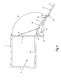
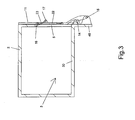
- the pivotally mounted door in the bottom of the opening is shown in a completely open position at the figure 2 . In the closed position as shown in figure 3 , the door is arranged vertically. The positions of inclination towards the bottom or vertical of the door are of course defined with reference to a horizontal floor joined to the frame 2.
- the second articulation 15 between the board 11 of the running board and the frame 2 is disposed parallel to the first hinge 14, the second hinge 15 being disposed with its axis of rotation offset from the first.
- This second hinge 15 is fixed to a portion 48 of the frame disposed below the opening 1. It could also fix the second hinge 15 by tabs being fixed under the floor 30, as will be described later.
- the first and second articulations are arranged horizontally so that the door 4 constitutes an access ramp in the open position.
- the access system according to the invention advantageously makes it possible to maintain a plane and horizontal vehicle floor 30 while having a raised floor.
- the second articulation 15 between the frame 2 and the panel 11 of the step is disposed at a height less than the first hinge 14 and is offset horizontally outwardly of the passenger compartment 3 relative to the first hinge 14.
- the axes of the first, second, third and fourth joints, referenced 14, 15, 16 and 17, are parallel to each other and are arranged along the four corners of a deformable parallelogram between an open position and a closed position of the door.
- the access system has a surface 27 of the running board on which it is possible to walk and which forms a first step extended by a surface 28 of the wing 5 of the door 4 forming a second step to access the cockpit 3.
- the door 4 is for example movable between its closed position shown in FIG. figure 3 and a maximum open position represented at the figure 2 , according to a maximum angular displacement, referenced 51, between 90 ° and 135 °.
- the panel 11 of the step is made with a dimension greater than that of the door so as to exceed in height relative to the leaf 5 of the door when the latter is in the closed position.
- the free edge of the board 11 of the step will again move away from the free edge of the door 5 of the door.
- the free edge here designates the edge opposite to that related to the articulation of the panel or the wing.
- the access system was represented on the Figures 1 to 3 without outer shielding plates.
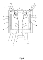
- An example of positioning outer shielding plates on the frame, on the door and on the step is shown in FIG. figure 4 .
- the access system is represented according to a front view, in the closed position.
- the door and the footboard of the access system as well as the cockpit are equipped with external shielding plates.
- the outer plates of shielding are supported by shock absorbing elements such as rigid spacers or metal foam.
- first outer shield plates 8 which appear in particular on the lateral sides of the passenger compartment as shown in FIG. figure 4 .
- These first outer shielding plates 8 are covered at the junction with second outer shielding plates 6 fixed to the door leaf and to the junction with third outer shielding plates 12 attached to the footboard.
- the reference 36 designates the edges of the outer shielding plates 8 fixed to the frame.
- Reference 37 designates the edges of the outer shield plates attached to the door leaf.
- Reference 38 denotes the edges of the outer shielding plates attached to the footboard.
- the third outer shielding plates 12 overlap the second outer shielding plates 6 which themselves overlap the first outer shielding plates 8.
- the third outer shielding plates 12 also overlap the first outer shielding plates 8.
- the first outer shielding plates 8 leave an uncovered zone 56 of the frame 2 on either side of the opening 1.
- This zone 56 which appears at the figure 5 , defines housing 24 for the actuators 22 and is disposed vis-a-vis the second external shielding plates 6 fixed to the door.
- the location of the opening 1 corresponds substantially to that of the door leaf in the closed position. The actuators can thus be protected by the door 4 while being arranged outside the passenger compartment.
- This zone 57 which appears at the figure 6 , includes an extension allowing the positioning of the step and also defines housing 25 for the drive elements 23 of the step 10 by the door 4.
- This zone 57 of the leaf not covered by the second external shielding plates 6 of the door is covered by the third external shielding plates 12 of the step which thus come opposite this zone.
- the step When the access system is in the closed position, the step is positioned partially recessed with respect to the shielding plates of the door, so that the third external shielding plates 12 of the step are pressed against the second plates 6 external shielding of the door. Similarly, the closed door is arranged so that the second outer shielding plates 6 of the door are pressed against the outer outer plates 8 shielding the frame.
- a part of the frame not covered by the first outer shielding plates 8 but covered by the third outer shield plates 12 of the step is also provided, above the opening 1, a part of the frame not covered by the first outer shielding plates 8 but covered by the third outer shield plates 12 of the step.
- This allows in particular to provide a step exceeding the height of the gate 5 of the door in the closed position of the access system.
- the additional height of the step allows for extra length for the first step.
- the dimensions of the first step can thus be chosen according to the needs and in particular according to the final height that is desired between the step and the ground when the ramp is in the open position.
- the first hinge 14 will be made by two hinges arranged under the lateral parts of the opening 1.
- the step will for example be articulated by a single central hinge forming the second hinge 15.
- the panel 11 of the step 10 comprises a rectangular portion forming the first step 27, extending by a portion 59 of smaller dimension and trapezoidal and then by a rectangular portion 60 elongated and of width substantially corresponding to the width of the central hinge forming the second joint.
- the figures 5 , 6 and 7 respectively represent an opening, a door 4 and a step 10 shown alone and corresponding to the access system mounted on an opening and shown in FIG. figure 8 .
- the figure 5 represents an opening 1 arranged in an armored vehicle.
- the opening 1 is disposed at the rear of the vehicle 31.
- vehicle 31 shown is a raised vehicle with a horizontal interior floor.
- the floor 30 is disposed horizontally when the vehicle is flat.
- the first shield plates 8 of the frame 2 leave an uncovered area 56 disposed above and on the sides of the opening 1.
- the actuator 22 right side in the plane of the figure, the access system appears on one side of the opening 1, the actuator 22 disposed opposite left side being partially masked by the outer shielding plates 8 fixed on the frame of the cockpit.
- Each actuator 22 is connected at each of its ends to a hinge axis.
- a housing 52 of the hinge 21 with the door is shown alone, at the lower end of the actuator 22.
- An articulation 20 with the frame 2 is provided at the upper end of the actuator 22.
- These two joints 20 and 21 have their axis of rotation parallel to that of the articulations 14 and 15 of the door 4 and the step 10.
- the first outer shield plates 8 are fixed to the frame by shock absorption elements in the form of spacers 9.
- the shock absorption elements have a predetermined thickness to achieve, in this thickness, housing for the actuators.
- An end stop element 26 is in the form of a compass hinged relative to the frame 2 and disposed opposite the opening 1.
- compass an assembly of two bars articulated to each other and also articulated: one on the frame and the other on the door.
- the maximum length of the unfolded hinged compass makes it possible to limit the stroke of the door leaf. In this way the forces exerted on the steps 27 and 28 in the maximum open position, are supported by the abutment member 26 and not by the actuators.
- the axes 53 of the hinges forming the first hinge 14 of the door with the frame are represented alone in the figure 5 . These axes 53 are each held by a fastener to the frame, each of these members being fixed under the floor 30 by means of bolts 18. These pins 53 are intended to cooperate with housings 42 made on the door 4.
- the axis 54 of the hinge forming the second articulation 15 of the step with the frame is represented alone ( figure 5 ).
- This axis 54 is held by a fastener to the frame, this member being fixed under the floor 30 by means of bolts 19.
- This fixing member comprises tabs 47 fixed by the bolts 19 and a reinforcing piece 58 welded to the portion 48 of the chassis disposed under the opening 1.
- the axis 54 of the hinge is intended to cooperate with a housing 55 formed on the step 10.
- the flap 5 includes reinforcement areas 41 thicker.
- the shock absorbing elements 7 supporting the second outer shielding plates 6 are for example spacers 7 supported against zones 41 of reinforcement.
- the second shielding plates 6 leave an uncovered zone 57 of the gate 5 of the door, this zone 57 being central and extending over the entire height of the door. It appears in particular in the middle part of the door a free space not covered by the second shielding plates 6 substantially corresponding to the profile of the step 10.
- the driving elements 23 of the running board 10 are arranged at the height of the rectangular element of the step 10 forming the first step 27.
- Each drive element 23 is connected to the leaf 5 of the door 4 by a hinge 16.
- the drive elements 23 of the step are arranged in the top of the door 4.
- Two joints 16 and 17 are provided at the ends of each element. 23 training.
- the door 4 also comprises members carrying the housings 42 for the axes 53 of the first articulation 14 between the door and the frame. These housings 42 are arranged in the bottom of the door 4.
- a member 49 for locking the door in the closed position is disposed at the top of the door.
- the second shielding plates 6 also protrude on each side of the leaf 5 of the door 4.
- the third outer shielding plates 12 form a protective shield protruding from both sides of the panel 11.
- the board 11 of the step comprises an elongate rectangular portion 60 tilting towards the passenger compartment and width corresponding substantially to that of the tabs 47 of the second articulation 15 between the frame and the step.
- This portion and a portion 59 of trapezoidal shape is formed in particular by two side members of the panel 11.
- the trapezoidal portion 59 is continued by a rectangular portion which forms the first step 27 when the access system is in the open position .
- the housing 55 for the axis 54 of the second articulation 15 is arranged in the bottom of the step 10.
- the figure 8 represents the access system in an intermediate position between the closed position and the maximum open position.
- the step 10 has moved away from the door 4 and in particular the third external shielding plates 12 of the step 10 have moved away from the second shielding plates 6 of the door, whereas these plates were pressed against each other in the closed position of the access system.
- a drive element 23 is visible between the leaf 5 of the door and the panel 11 of the footboard.
- the second outer shielding plates 6 of the door parallel to the leaf 5 of the door, are inclined at an angle of approximately 45 ° with respect to a vertical position of closure of the opening 1.
- the actuators 22 connected by two joints at both ends, pivot to follow the movement of the wing 5, when the actuator 22 extends or shortens.
- the end stop element 26 connected to the inner face of the leaf 5 of the door, leaves part of the passenger compartment. There are two limit stop members of the door in the maximum open position. These two end stop members 26 are here in the form of a compass. The limit stop members and the hydraulic actuators are here linked to the lateral parts of the door.
- the vehicle represented figures 8 , 9 and 10 is an armored and elevated military vehicle.
- the vehicle 31 equipped with the access system according to the invention is thus equipped with a floor 30 raised and horizontal.
- the limit stop compass 26 is in maximum extension.
- the stop element 26 in particular relieves the actuator 22 which no longer has to support the door or the step as long as the access system remains in the maximum open position.
- An operator 33 was represented, at the figure 9 , in several successive positions during its rise in the vehicle 31.
- the operator 33 from the ground 34, is based on the first step 27 of the access system.
- This first step 27 is formed by the end of the panel 11 of the step 10.
- the free end of the panel 11 of the step is here inclined downwards.
- the door 5 of the door 4 is inclined in a position with its free edge inclined downwards.
- the user 33 places a foot on the second step 28.
- the second step 28 is made by a side of the door 5 of the door.
- the user 33 can then put a second foot on the second step to then enter the cabin of the vehicle.
- FIG. 10 An overview of a vehicle viewed from the side corresponding to the figure 9 is represented at the figure 10 .
- the frame is formed by the chassis of the vehicle, its floor and the cabin at the rear of the vehicle.
Landscapes
- Engineering & Computer Science (AREA)
- Health & Medical Sciences (AREA)
- Public Health (AREA)
- General Engineering & Computer Science (AREA)
- Life Sciences & Earth Sciences (AREA)
- Mechanical Engineering (AREA)
- Transportation (AREA)
- Animal Behavior & Ethology (AREA)
- General Health & Medical Sciences (AREA)
- Veterinary Medicine (AREA)
- Vehicle Step Arrangements And Article Storage (AREA)
- Body Structure For Vehicles (AREA)
- Hinges (AREA)
Claims (10)
- Zugangssystem zu einem Fahrgastraum (3) für ein gepanzertes Fahrzeug durch eine Öffnung (1), welche in einem Gestell (2) des Fahrgastraums (3) eingebracht ist, wobei das Zugangssystem von wenigstens einer Tür (4) gebildet wird, welche über ein erstes horizontales Gelenk (14) gelenkig in Bezug auf das Gestell (2) angebracht ist und eine geneigte Rampe in geöffneter Position bildet, wobei das System wenigstens ein Stellglied (22), um die Tür (4) in Bewegung zu setzen, in Verbindung mit der Tür (4) und dem Gestell (2), sowie ein Trittbrett umfasst, dadurch gekennzeichnet, dass das genannte Trittbrett (10) wenigstens zum Teil das Äußere der Tür bedeckt und gelenkig in Bezug auf das Gestell (2) über ein zweites Gelenk (15), welches parallel zum ersten Gelenk ist und eine zu diesem versetzte Achse aufweist, angebracht ist, wobei das Trittbrett (10) mit der Tür (4) über wenigstens ein Antriebsmittel (23) verbunden ist, welches über ein drittes Gelenk (16) mit der Tür (4) und über ein viertes Gelenk (17) mit dem Trittbrett (10) verbunden ist, wobei die Achsen des ersten, zweiten, dritten und vierten Gelenkes (14, 15, 16, 17) parallel zueinander und eingerichtet sind, um die vier Scheitelpunkte eines Parallelogramms zu bilden, welches zwischen einer geöffneten und einer geschlossenen Position der Tür (4) verformbar ist.
- Zugangssystem nach Anspruch 1, dadurch gekennzeichnet, dass das erste Gelenk (14) mit dem unteren Rand (32) der Tür (4) und mit dem unteren Rand (46) der Öffnung in Verbindung steht, wobei das zweite Gelenk (15) unterhalb des ersten liegt und horizontal nach außen des Fahrgastraumes (3) in Bezug auf das erste angeordnet ist.
- Zugangssystem nach einem der vorhergehenden Ansprüche, dadurch gekennzeichnet, dass das Trittbrett (10) eine größere Abmessung als diejenige der Tür (4) derartig aufweist, dass es die Tür (4) in der Höhe überragt, wenn sich diese in geschlossener Position befindet.
- Zugangssystem nach einem der vorhergehenden Ansprüche, dadurch gekennzeichnet, dass der Fahrgastraum (3) mit ersten äußeren Platten zur Panzerung (8) ausgerüstet ist, welche durch erste Elemente zur Absorption von Stößen (9) am Gestell (2) befestigt sind, wobei die Tür einen Drehflügel (5) umfasst, welcher mit dem genannten ersten Gelenk (14) verbunden ist und mit zweiten äußeren Platten zur Panzerung (6) ausgerüstet ist, welche durch zweite Elemente zur Absorption von Stößen (7) am Drehflügel (5) befestigt sind, wobei das Trittbrett eine Tafel (11) umfasst, welche mit dem zweiten Gelenk (15) verbunden und mit dritten äußeren Platten zur Panzerung (12) ausgerüstet ist, welche durch dritte Elemente zur Absorption von Stößen (13) an der Tafel (11) befestigt sind.
- Zugangssystem nach Anspruch 4, dadurch gekennzeichnet, dass die dritten äußeren Platten zur Panzerung (12) teilweise über den zweiten äußeren Platten zur Panzerung (6) liegen, welche ihrerseits teilweise über den ersten äußeren Platten zur Panzerung (8) liegen.
- Zugangssystem nach Anspruch 4 oder 5, dadurch gekennzeichnet, dass die ersten äußeren Platten zur Panzerung (8) wenigstens eine erste, nicht bedeckte Zone (56) des Gestells (2) übrig lassen, welche eine Aufnahme (24) des genannten Stellgliedes der Tür abgrenzt, wobei die genannte erste Zone von den zweiten äußeren Platten zur Panzerung (6) bedeckt wird.
- Zugangssystem nach einem der Ansprüche 4 bis 6, dadurch gekennzeichnet, dass die zweiten äußeren Platten zur Panzerung (6) eine zweite, nicht bedeckte Zone (57) des Drehflügels (5) der Tür (4) übrig lassen, wobei diese zweite Zone wenigstens eine Aufnahme (25) des Antriebsmittels des Trittbretts und die Aufnahme für die Tafel (11) abgrenzt, wobei die zweite Zone von den dritten äußeren Platten zur Panzerung (12) bedeckt wird.
- Zugangssystem nach einem der vorhergehenden Ansprüche, dadurch gekennzeichnet, dass die Tür (4) zwischen ihrer geschlossenen Position und ihrer ausgeklappten Position entsprechend einem maximalen Ausschlagwinkel beweglich ist, welcher zwischen 90° und 135° liegt.
- Zugangssystem nach einem der vorhergehenden Ansprüche, dadurch gekennzeichnet, dass es wenigstens ein Organ (26) zum Endlagenanschlag der Tür in der Position der maximalen Öffnung umfasst.
- Fahrzeug (31) umfassend einen Fahrgastraum, welcher mit einem Zugangssystem nach einem der vorhergehenden Ansprüche ausgerüstet ist.
Priority Applications (1)
| Application Number | Priority Date | Filing Date | Title |
|---|---|---|---|
| PL12290296T PL2573501T3 (pl) | 2011-09-26 | 2012-09-10 | System dostępu do przedziału pasażerskiego |
Applications Claiming Priority (1)
| Application Number | Priority Date | Filing Date | Title |
|---|---|---|---|
| FR1102908A FR2980418B1 (fr) | 2011-09-26 | 2011-09-26 | Systeme d'acces a un habitacle |
Publications (2)
| Publication Number | Publication Date |
|---|---|
| EP2573501A1 EP2573501A1 (de) | 2013-03-27 |
| EP2573501B1 true EP2573501B1 (de) | 2014-04-02 |
Family
ID=46832314
Family Applications (1)
| Application Number | Title | Priority Date | Filing Date |
|---|---|---|---|
| EP12290296.8A Active EP2573501B1 (de) | 2011-09-26 | 2012-09-10 | Zugangssystem zu einem Fahrzeuginnenraum |
Country Status (6)
| Country | Link |
|---|---|
| US (1) | US8870269B2 (de) |
| EP (1) | EP2573501B1 (de) |
| CA (1) | CA2790463C (de) |
| ES (1) | ES2476220T3 (de) |
| FR (1) | FR2980418B1 (de) |
| PL (1) | PL2573501T3 (de) |
Cited By (1)
| Publication number | Priority date | Publication date | Assignee | Title |
|---|---|---|---|---|
| RU2614368C1 (ru) * | 2016-01-12 | 2017-03-24 | Анатолий Павлович Ефимочкин | Боевая машина пехоты |
Families Citing this family (19)
| Publication number | Priority date | Publication date | Assignee | Title |
|---|---|---|---|---|
| EP2777667A3 (de) | 2013-03-15 | 2016-03-16 | Valeda Company Llc. (Dba Q'Straint) | Rollstuhlsicherungssystem und Vorrichtung für rollstuhlgerechte Fahrzeuge |
| FR3005156B1 (fr) * | 2013-04-29 | 2016-01-15 | Nexter Systems | Vehicule equipe d'un dispositif de protection d'ouvrant assurant une optimisation du gabarit d'ouverture |
| US9597240B2 (en) | 2013-05-30 | 2017-03-21 | The Braun Corporation | Vehicle accessibility system |
| FR3016960B1 (fr) * | 2014-01-27 | 2018-04-13 | Nexter Systems | Vehicule blinde comportant un moyen moteur d'ouverture |
| TR201414218A2 (tr) * | 2014-11-28 | 2016-06-21 | Otokar Otomotiv Ve Savunma Sanayi Anonim Sirketi | Hidrolik pistonlu ve koruma kapaklarına sahip bir rampa kapı mekanizması. |
| KR200485860Y1 (ko) * | 2016-03-31 | 2018-03-07 | 주식회사 성원 | 중장비차량용 방탄탑 및 방탄탑 조립방법 |
| CN106837100B (zh) * | 2016-12-27 | 2018-08-14 | 北京北方车辆集团有限公司 | 一种电动控制跳板式后舱门机构 |
| DE102018113755A1 (de) * | 2018-06-08 | 2019-12-12 | Rheinmetall Landsysteme Gmbh | Fahrzeugtür |
| KR102726808B1 (ko) * | 2019-12-06 | 2024-11-05 | 현대자동차주식회사 | 로워 도어 개방구조 |
| KR102935077B1 (ko) * | 2019-12-06 | 2026-03-05 | 현대자동차주식회사 | 로워 도어 승하차 지지구조 |
| JP2021155004A (ja) * | 2020-03-30 | 2021-10-07 | 本田技研工業株式会社 | 車体後部構造 |
| US11305697B1 (en) | 2020-08-07 | 2022-04-19 | Arizona Safari Jeep Tours, LLC | Vehicle entry systems |
| USD941738S1 (en) | 2020-08-07 | 2022-01-25 | Arizona Safari Jeep Tours, L.L.C. | Vehicle roll cage |
| USD986796S1 (en) | 2020-08-07 | 2023-05-23 | Arizona Safari Jeep Tours Llc | Vehicle roll cage |
| US20230061330A1 (en) * | 2021-08-25 | 2023-03-02 | Byron Norman Ricketts | Folding tailgate ramp system |
| DE102021126174A1 (de) | 2021-10-08 | 2023-04-13 | Rheinmetall Landsysteme Gmbh | Gepanzertes Fahrzeug mit Notausstiegsluke |
| DE102021126173A1 (de) | 2021-10-08 | 2023-04-13 | Rheinmetall Landsysteme Gmbh | Gepanzertes Fahrzeug mit Notausstiegsluke |
| CN114963878A (zh) * | 2022-05-31 | 2022-08-30 | 湖北纽睿德防务科技有限公司 | 一种越野防雷巡逻车 |
| CN118544953B (zh) * | 2024-07-29 | 2024-10-18 | 江西江铃汽车集团改装车股份有限公司 | 一种用于车辆方舱的舷梯 |
Family Cites Families (17)
| Publication number | Priority date | Publication date | Assignee | Title |
|---|---|---|---|---|
| US3606382A (en) * | 1969-03-14 | 1971-09-20 | Lloyd C Pollock | Truck tail gate steps |
| US4235047A (en) * | 1979-05-15 | 1980-11-25 | Harsco Corporation | Armored door opener for field artillery ammunition support vehicle |
| US4953492A (en) * | 1989-06-21 | 1990-09-04 | Fmc Corporation | Water supporting and propulsion systems |
| GB9213452D0 (en) | 1992-06-24 | 1992-08-05 | London Taxis International Lim | Wheelchair access systems for vehicles |
| US5579711A (en) * | 1996-02-06 | 1996-12-03 | United Defense, L.P. | Extendible thrust vectoring transom panel |
| ATE185896T1 (de) * | 1996-08-20 | 1999-11-15 | Wegmann & Co Gmbh | Gefechtsfahrzeug mit dieselelektrischem antrieb und heckluke |
| GB9816374D0 (en) | 1998-07-29 | 1998-09-23 | Uvg Ambulances Limited | Access apparatus |
| ITTO20010128U1 (it) * | 2001-07-25 | 2003-01-25 | Aris Spa | Struttura ausiliaria particolarmente per l'incremento della capacita'di trasporto dei veicoli cingolati polivalenti tipo m 113 e derivati. |
| GB2419339A (en) | 2004-10-19 | 2006-04-26 | Rampdoors Ltd | Access apparatus for an access structure |
| FR2898839B1 (fr) * | 2006-03-23 | 2009-02-27 | Giat Ind Sa | Dispositif d'embarquement et de debarquement d'un module mobile |
| US7484749B1 (en) * | 2006-04-17 | 2009-02-03 | United States Of America As Represented By The Secretary Of The Navy | Frame tow-bar adapter |
| GB0700174D0 (en) | 2007-01-05 | 2007-02-14 | Lateral Design Concepts Ltd | Access apparatus |
| US8091943B1 (en) * | 2007-07-17 | 2012-01-10 | Weber Robert M | Apparatus and method for accessing the bed of a pickup truck |
| US8091942B2 (en) * | 2008-11-19 | 2012-01-10 | Gumbo Product Development, Inc. | Recreational vehicle with ramp door |
| CN101881583B (zh) * | 2010-06-11 | 2015-06-10 | 中国重汽集团青岛重工有限公司 | 轮式装甲防暴车 |
| US8657353B2 (en) * | 2010-09-13 | 2014-02-25 | Milton Manufacturing, Inc. | Auto deployed cargo loading rail system and medic seat in-truck travel rail |
| FR2977020B1 (fr) * | 2011-06-22 | 2014-03-07 | Nexter Systems | Vehicule blinde comportant une rampe d'acces basculante. |
-
2011
- 2011-09-26 FR FR1102908A patent/FR2980418B1/fr not_active Expired - Fee Related
-
2012
- 2012-09-07 CA CA2790463A patent/CA2790463C/fr not_active Expired - Fee Related
- 2012-09-10 PL PL12290296T patent/PL2573501T3/pl unknown
- 2012-09-10 EP EP12290296.8A patent/EP2573501B1/de active Active
- 2012-09-10 ES ES12290296.8T patent/ES2476220T3/es active Active
- 2012-09-25 US US13/626,327 patent/US8870269B2/en not_active Expired - Fee Related
Cited By (1)
| Publication number | Priority date | Publication date | Assignee | Title |
|---|---|---|---|---|
| RU2614368C1 (ru) * | 2016-01-12 | 2017-03-24 | Анатолий Павлович Ефимочкин | Боевая машина пехоты |
Also Published As
| Publication number | Publication date |
|---|---|
| CA2790463A1 (fr) | 2013-03-26 |
| FR2980418B1 (fr) | 2013-10-25 |
| EP2573501A1 (de) | 2013-03-27 |
| US20130074686A1 (en) | 2013-03-28 |
| US8870269B2 (en) | 2014-10-28 |
| FR2980418A1 (fr) | 2013-03-29 |
| PL2573501T3 (pl) | 2014-09-30 |
| CA2790463C (fr) | 2017-04-25 |
| ES2476220T3 (es) | 2014-07-14 |
Similar Documents
| Publication | Publication Date | Title |
|---|---|---|
| EP2573501B1 (de) | Zugangssystem zu einem Fahrzeuginnenraum | |
| FR2636219A1 (fr) | Agencement de meuble dans une construction et vehicule, tel que caravane, comprenant un meuble mobile | |
| EP2877094B1 (de) | Schirm aus einem strahlenschutzmaterial zum schutz eines bedieners vor ionisierender strahlung | |
| CA2760396A1 (fr) | Dispositif de protection balistique deportee destine a couvrir completement une porte | |
| CA2838307C (fr) | Vehicule blinde comportant une rampe d'acces basculante | |
| FR2587322A1 (fr) | Cabine pour chariot elevateur industriel et chariot elevateur industriel equipe d'une telle cabine. | |
| EP2917069B1 (de) | Anordnung zur formung einer zugangsrampe für personen mit eingeschränkter mobilität und damit ausgestattetes fahrzeug | |
| EP2904176B1 (de) | Beckenabdeckung | |
| WO2017042391A1 (fr) | Système d'ouverture de hayon présentant plusieurs cinématiques d'ouverture | |
| FR3102452A1 (fr) | Caisson comprenant une porte de type accordeon a multiples panneaux pour un vehicule automobile | |
| FR2783909A1 (fr) | Blindage avance de tourelle | |
| EP3670271B1 (de) | Bewegungsvorrichtung einer kamera für ein motorgetriebenes fahrzeug | |
| FR3059609B1 (fr) | Dispositif d'articulation d'une porte laterale de vehicule | |
| WO2012059396A1 (fr) | Dispositif de protection laterale pour un vehicule | |
| FR2881462A1 (fr) | Trappe pivotante | |
| FR3117011A1 (fr) | Dispositif d’accès à une cabine de pilotage d’un véhicule lourd, et véhicule lourd équipé d’un tel dispositif d’accès | |
| EP2634524B1 (de) | Vorrichtung zur Positionieren eine ballistische Panzerungsplatte und Struktur mit einer solchen Vorrichtung | |
| FR2914590A1 (fr) | Vehicule automobile a panneau de toit ouvrant. | |
| FR2882445A1 (fr) | Dispositif d'observation a episcope escamotable | |
| WO2023104934A1 (fr) | Dispositif lumineux d'un véhicule automobile | |
| FR2974330A1 (fr) | Vehicule utilitaire comprenant une cellule arriere avec une baie obturee par un store, et cellule arriere correspondante | |
| FR2529149A1 (fr) | Dispositif d'assistance au fonctionnement des caravanes pliantes rigides | |
| FR2933337A3 (fr) | Agencement d'une porte d'un vehicule automobile dans un cadre de porte d'un cote de caisse | |
| FR2979087A1 (fr) | Dispositif de protection d'habitacle pour ouverture exposee aux intemperies. |
Legal Events
| Date | Code | Title | Description |
|---|---|---|---|
| PUAI | Public reference made under article 153(3) epc to a published international application that has entered the european phase |
Free format text: ORIGINAL CODE: 0009012 |
|
| AK | Designated contracting states |
Kind code of ref document: A1 Designated state(s): AL AT BE BG CH CY CZ DE DK EE ES FI FR GB GR HR HU IE IS IT LI LT LU LV MC MK MT NL NO PL PT RO RS SE SI SK SM TR |
|
| AX | Request for extension of the european patent |
Extension state: BA ME |
|
| 17P | Request for examination filed |
Effective date: 20130911 |
|
| RBV | Designated contracting states (corrected) |
Designated state(s): AL AT BE BG CH CY CZ DE DK EE ES FI FR GB GR HR HU IE IS IT LI LT LU LV MC MK MT NL NO PL PT RO RS SE SI SK SM TR |
|
| GRAP | Despatch of communication of intention to grant a patent |
Free format text: ORIGINAL CODE: EPIDOSNIGR1 |
|
| RIC1 | Information provided on ipc code assigned before grant |
Ipc: B60P 1/43 20060101ALI20131014BHEP Ipc: F41H 5/22 20060101AFI20131014BHEP Ipc: A61G 3/06 20060101ALI20131014BHEP Ipc: F41H 7/02 20060101ALI20131014BHEP |
|
| INTG | Intention to grant announced |
Effective date: 20131120 |
|
| GRAS | Grant fee paid |
Free format text: ORIGINAL CODE: EPIDOSNIGR3 |
|
| GRAA | (expected) grant |
Free format text: ORIGINAL CODE: 0009210 |
|
| AK | Designated contracting states |
Kind code of ref document: B1 Designated state(s): AL AT BE BG CH CY CZ DE DK EE ES FI FR GB GR HR HU IE IS IT LI LT LU LV MC MK MT NL NO PL PT RO RS SE SI SK SM TR |
|
| REG | Reference to a national code |
Ref country code: GB Ref legal event code: FG4D Free format text: NOT ENGLISH |
|
| REG | Reference to a national code |
Ref country code: AT Ref legal event code: REF Ref document number: 660385 Country of ref document: AT Kind code of ref document: T Effective date: 20140415 Ref country code: CH Ref legal event code: EP |
|
| REG | Reference to a national code |
Ref country code: IE Ref legal event code: FG4D Free format text: LANGUAGE OF EP DOCUMENT: FRENCH |
|
| REG | Reference to a national code |
Ref country code: DE Ref legal event code: R096 Ref document number: 602012001299 Country of ref document: DE Effective date: 20140515 |
|
| REG | Reference to a national code |
Ref country code: ES Ref legal event code: FG2A Ref document number: 2476220 Country of ref document: ES Kind code of ref document: T3 Effective date: 20140714 |
|
| REG | Reference to a national code |
Ref country code: SE Ref legal event code: TRGR |
|
| REG | Reference to a national code |
Ref country code: NL Ref legal event code: VDEP Effective date: 20140402 |
|
| REG | Reference to a national code |
Ref country code: LT Ref legal event code: MG4D |
|
| REG | Reference to a national code |
Ref country code: PL Ref legal event code: T3 |
|
| PG25 | Lapsed in a contracting state [announced via postgrant information from national office to epo] |
Ref country code: LT Free format text: LAPSE BECAUSE OF FAILURE TO SUBMIT A TRANSLATION OF THE DESCRIPTION OR TO PAY THE FEE WITHIN THE PRESCRIBED TIME-LIMIT Effective date: 20140402 Ref country code: NL Free format text: LAPSE BECAUSE OF FAILURE TO SUBMIT A TRANSLATION OF THE DESCRIPTION OR TO PAY THE FEE WITHIN THE PRESCRIBED TIME-LIMIT Effective date: 20140402 Ref country code: CY Free format text: LAPSE BECAUSE OF FAILURE TO SUBMIT A TRANSLATION OF THE DESCRIPTION OR TO PAY THE FEE WITHIN THE PRESCRIBED TIME-LIMIT Effective date: 20140402 Ref country code: GR Free format text: LAPSE BECAUSE OF FAILURE TO SUBMIT A TRANSLATION OF THE DESCRIPTION OR TO PAY THE FEE WITHIN THE PRESCRIBED TIME-LIMIT Effective date: 20140703 Ref country code: NO Free format text: LAPSE BECAUSE OF FAILURE TO SUBMIT A TRANSLATION OF THE DESCRIPTION OR TO PAY THE FEE WITHIN THE PRESCRIBED TIME-LIMIT Effective date: 20140702 Ref country code: BG Free format text: LAPSE BECAUSE OF FAILURE TO SUBMIT A TRANSLATION OF THE DESCRIPTION OR TO PAY THE FEE WITHIN THE PRESCRIBED TIME-LIMIT Effective date: 20140702 Ref country code: IS Free format text: LAPSE BECAUSE OF FAILURE TO SUBMIT A TRANSLATION OF THE DESCRIPTION OR TO PAY THE FEE WITHIN THE PRESCRIBED TIME-LIMIT Effective date: 20140802 Ref country code: CZ Free format text: LAPSE BECAUSE OF FAILURE TO SUBMIT A TRANSLATION OF THE DESCRIPTION OR TO PAY THE FEE WITHIN THE PRESCRIBED TIME-LIMIT Effective date: 20140402 |
|
| PG25 | Lapsed in a contracting state [announced via postgrant information from national office to epo] |
Ref country code: LV Free format text: LAPSE BECAUSE OF FAILURE TO SUBMIT A TRANSLATION OF THE DESCRIPTION OR TO PAY THE FEE WITHIN THE PRESCRIBED TIME-LIMIT Effective date: 20140402 Ref country code: RS Free format text: LAPSE BECAUSE OF FAILURE TO SUBMIT A TRANSLATION OF THE DESCRIPTION OR TO PAY THE FEE WITHIN THE PRESCRIBED TIME-LIMIT Effective date: 20140402 Ref country code: HR Free format text: LAPSE BECAUSE OF FAILURE TO SUBMIT A TRANSLATION OF THE DESCRIPTION OR TO PAY THE FEE WITHIN THE PRESCRIBED TIME-LIMIT Effective date: 20140402 |
|
| PG25 | Lapsed in a contracting state [announced via postgrant information from national office to epo] |
Ref country code: PT Free format text: LAPSE BECAUSE OF FAILURE TO SUBMIT A TRANSLATION OF THE DESCRIPTION OR TO PAY THE FEE WITHIN THE PRESCRIBED TIME-LIMIT Effective date: 20140804 |
|
| REG | Reference to a national code |
Ref country code: DE Ref legal event code: R097 Ref document number: 602012001299 Country of ref document: DE |
|
| PG25 | Lapsed in a contracting state [announced via postgrant information from national office to epo] |
Ref country code: EE Free format text: LAPSE BECAUSE OF FAILURE TO SUBMIT A TRANSLATION OF THE DESCRIPTION OR TO PAY THE FEE WITHIN THE PRESCRIBED TIME-LIMIT Effective date: 20140402 Ref country code: RO Free format text: LAPSE BECAUSE OF FAILURE TO SUBMIT A TRANSLATION OF THE DESCRIPTION OR TO PAY THE FEE WITHIN THE PRESCRIBED TIME-LIMIT Effective date: 20140402 Ref country code: SK Free format text: LAPSE BECAUSE OF FAILURE TO SUBMIT A TRANSLATION OF THE DESCRIPTION OR TO PAY THE FEE WITHIN THE PRESCRIBED TIME-LIMIT Effective date: 20140402 Ref country code: DK Free format text: LAPSE BECAUSE OF FAILURE TO SUBMIT A TRANSLATION OF THE DESCRIPTION OR TO PAY THE FEE WITHIN THE PRESCRIBED TIME-LIMIT Effective date: 20140402 |
|
| PLBE | No opposition filed within time limit |
Free format text: ORIGINAL CODE: 0009261 |
|
| STAA | Information on the status of an ep patent application or granted ep patent |
Free format text: STATUS: NO OPPOSITION FILED WITHIN TIME LIMIT |
|
| 26N | No opposition filed |
Effective date: 20150106 |
|
| REG | Reference to a national code |
Ref country code: DE Ref legal event code: R097 Ref document number: 602012001299 Country of ref document: DE Effective date: 20150106 |
|
| PG25 | Lapsed in a contracting state [announced via postgrant information from national office to epo] |
Ref country code: MC Free format text: LAPSE BECAUSE OF FAILURE TO SUBMIT A TRANSLATION OF THE DESCRIPTION OR TO PAY THE FEE WITHIN THE PRESCRIBED TIME-LIMIT Effective date: 20140402 Ref country code: LU Free format text: LAPSE BECAUSE OF FAILURE TO SUBMIT A TRANSLATION OF THE DESCRIPTION OR TO PAY THE FEE WITHIN THE PRESCRIBED TIME-LIMIT Effective date: 20140910 |
|
| PG25 | Lapsed in a contracting state [announced via postgrant information from national office to epo] |
Ref country code: RS Free format text: LAPSE BECAUSE OF FAILURE TO SUBMIT A TRANSLATION OF THE DESCRIPTION OR TO PAY THE FEE WITHIN THE PRESCRIBED TIME-LIMIT Effective date: 20141119 |
|
| REG | Reference to a national code |
Ref country code: IE Ref legal event code: MM4A |
|
| PG25 | Lapsed in a contracting state [announced via postgrant information from national office to epo] |
Ref country code: BE Free format text: LAPSE BECAUSE OF NON-PAYMENT OF DUE FEES Effective date: 20140930 |
|
| PG25 | Lapsed in a contracting state [announced via postgrant information from national office to epo] |
Ref country code: SI Free format text: LAPSE BECAUSE OF FAILURE TO SUBMIT A TRANSLATION OF THE DESCRIPTION OR TO PAY THE FEE WITHIN THE PRESCRIBED TIME-LIMIT Effective date: 20140402 |
|
| PG25 | Lapsed in a contracting state [announced via postgrant information from national office to epo] |
Ref country code: IE Free format text: LAPSE BECAUSE OF NON-PAYMENT OF DUE FEES Effective date: 20140910 |
|
| PG25 | Lapsed in a contracting state [announced via postgrant information from national office to epo] |
Ref country code: SM Free format text: LAPSE BECAUSE OF FAILURE TO SUBMIT A TRANSLATION OF THE DESCRIPTION OR TO PAY THE FEE WITHIN THE PRESCRIBED TIME-LIMIT Effective date: 20140402 |
|
| PG25 | Lapsed in a contracting state [announced via postgrant information from national office to epo] |
Ref country code: MT Free format text: LAPSE BECAUSE OF FAILURE TO SUBMIT A TRANSLATION OF THE DESCRIPTION OR TO PAY THE FEE WITHIN THE PRESCRIBED TIME-LIMIT Effective date: 20140402 |
|
| PG25 | Lapsed in a contracting state [announced via postgrant information from national office to epo] |
Ref country code: HU Free format text: LAPSE BECAUSE OF FAILURE TO SUBMIT A TRANSLATION OF THE DESCRIPTION OR TO PAY THE FEE WITHIN THE PRESCRIBED TIME-LIMIT; INVALID AB INITIO Effective date: 20120910 |
|
| REG | Reference to a national code |
Ref country code: FR Ref legal event code: PLFP Year of fee payment: 5 |
|
| REG | Reference to a national code |
Ref country code: FR Ref legal event code: PLFP Year of fee payment: 6 |
|
| PG25 | Lapsed in a contracting state [announced via postgrant information from national office to epo] |
Ref country code: MK Free format text: LAPSE BECAUSE OF FAILURE TO SUBMIT A TRANSLATION OF THE DESCRIPTION OR TO PAY THE FEE WITHIN THE PRESCRIBED TIME-LIMIT Effective date: 20140402 |
|
| REG | Reference to a national code |
Ref country code: FR Ref legal event code: PLFP Year of fee payment: 7 |
|
| PG25 | Lapsed in a contracting state [announced via postgrant information from national office to epo] |
Ref country code: AL Free format text: LAPSE BECAUSE OF FAILURE TO SUBMIT A TRANSLATION OF THE DESCRIPTION OR TO PAY THE FEE WITHIN THE PRESCRIBED TIME-LIMIT Effective date: 20140402 |
|
| PGFP | Annual fee paid to national office [announced via postgrant information from national office to epo] |
Ref country code: AT Payment date: 20190822 Year of fee payment: 8 |
|
| PGFP | Annual fee paid to national office [announced via postgrant information from national office to epo] |
Ref country code: ES Payment date: 20191001 Year of fee payment: 8 |
|
| REG | Reference to a national code |
Ref country code: AT Ref legal event code: MM01 Ref document number: 660385 Country of ref document: AT Kind code of ref document: T Effective date: 20200910 |
|
| PG25 | Lapsed in a contracting state [announced via postgrant information from national office to epo] |
Ref country code: AT Free format text: LAPSE BECAUSE OF NON-PAYMENT OF DUE FEES Effective date: 20200910 |
|
| PGFP | Annual fee paid to national office [announced via postgrant information from national office to epo] |
Ref country code: FI Payment date: 20210816 Year of fee payment: 10 |
|
| PGFP | Annual fee paid to national office [announced via postgrant information from national office to epo] |
Ref country code: TR Payment date: 20210824 Year of fee payment: 10 Ref country code: SE Payment date: 20210819 Year of fee payment: 10 Ref country code: CH Payment date: 20210818 Year of fee payment: 10 Ref country code: PL Payment date: 20210820 Year of fee payment: 10 |
|
| REG | Reference to a national code |
Ref country code: ES Ref legal event code: FD2A Effective date: 20220117 |
|
| PG25 | Lapsed in a contracting state [announced via postgrant information from national office to epo] |
Ref country code: ES Free format text: LAPSE BECAUSE OF NON-PAYMENT OF DUE FEES Effective date: 20200911 |
|
| PG25 | Lapsed in a contracting state [announced via postgrant information from national office to epo] |
Ref country code: FI Free format text: LAPSE BECAUSE OF NON-PAYMENT OF DUE FEES Effective date: 20220910 |
|
| REG | Reference to a national code |
Ref country code: CH Ref legal event code: PL |
|
| REG | Reference to a national code |
Ref country code: SE Ref legal event code: EUG |
|
| P01 | Opt-out of the competence of the unified patent court (upc) registered |
Effective date: 20230601 |
|
| PG25 | Lapsed in a contracting state [announced via postgrant information from national office to epo] |
Ref country code: LI Free format text: LAPSE BECAUSE OF NON-PAYMENT OF DUE FEES Effective date: 20220930 Ref country code: CH Free format text: LAPSE BECAUSE OF NON-PAYMENT OF DUE FEES Effective date: 20220930 |
|
| PG25 | Lapsed in a contracting state [announced via postgrant information from national office to epo] |
Ref country code: SE Free format text: LAPSE BECAUSE OF NON-PAYMENT OF DUE FEES Effective date: 20220911 |
|
| PG25 | Lapsed in a contracting state [announced via postgrant information from national office to epo] |
Ref country code: PL Free format text: LAPSE BECAUSE OF NON-PAYMENT OF DUE FEES Effective date: 20220910 |
|
| PGFP | Annual fee paid to national office [announced via postgrant information from national office to epo] |
Ref country code: DE Payment date: 20250820 Year of fee payment: 14 |
|
| PGFP | Annual fee paid to national office [announced via postgrant information from national office to epo] |
Ref country code: IT Payment date: 20250820 Year of fee payment: 14 |
|
| PGFP | Annual fee paid to national office [announced via postgrant information from national office to epo] |
Ref country code: GB Payment date: 20250822 Year of fee payment: 14 |
|
| PGFP | Annual fee paid to national office [announced via postgrant information from national office to epo] |
Ref country code: FR Payment date: 20250820 Year of fee payment: 14 |