EP2573628A2 - Cadran de montre et montre - Google Patents
Cadran de montre et montre Download PDFInfo
- Publication number
- EP2573628A2 EP2573628A2 EP12184817A EP12184817A EP2573628A2 EP 2573628 A2 EP2573628 A2 EP 2573628A2 EP 12184817 A EP12184817 A EP 12184817A EP 12184817 A EP12184817 A EP 12184817A EP 2573628 A2 EP2573628 A2 EP 2573628A2
- Authority
- EP
- European Patent Office
- Prior art keywords
- dial
- decorative
- decorative member
- front side
- dial assembly
- Prior art date
- Legal status (The legal status is an assumption and is not a legal conclusion. Google has not performed a legal analysis and makes no representation as to the accuracy of the status listed.)
- Withdrawn
Links
Images


Classifications
-
- G—PHYSICS
- G04—HOROLOGY
- G04B—MECHANICALLY-DRIVEN CLOCKS OR WATCHES; MECHANICAL PARTS OF CLOCKS OR WATCHES IN GENERAL; TIME PIECES USING THE POSITION OF THE SUN, MOON OR STARS
- G04B47/00—Time-pieces combined with other articles which do not interfere with the running or the time-keeping of the time-piece
- G04B47/04—Time-pieces combined with other articles which do not interfere with the running or the time-keeping of the time-piece with attached ornaments or amusement apparatus
- G04B47/042—Fastening of jewels and the like
-
- G—PHYSICS
- G04—HOROLOGY
- G04B—MECHANICALLY-DRIVEN CLOCKS OR WATCHES; MECHANICAL PARTS OF CLOCKS OR WATCHES IN GENERAL; TIME PIECES USING THE POSITION OF THE SUN, MOON OR STARS
- G04B19/00—Indicating the time by visual means
- G04B19/06—Dials
- G04B19/10—Ornamental shape of the graduations or the surface of the dial; Attachment of the graduations to the dial
Definitions
- the present invention relates to a dial assembly and a timepiece.
- Patent Document 1 Japanese Laid-open Patent Application No. 2000-275360 is an example of the related art.
- An advantage of the invention is to provide a dial assembly for which it is possible to suppress the projection of the decorative member from the front side surface of the dial, and a timepiece equipped with that dial assembly.
- the dial assembly of the invention is a dial assembly which is held inside a timepiece case together with a movement that supports an hour hand and minute hand to be able to rotate, the dial assembly including:
- the support member is constituted with a block unit, and a projecting part is formed projecting to the side surface, engaging with the edge part of the fixing part, and regulates the insertion depth in relation to the fixing part.
- the insertion depth of the support member in relation to the fixing part is reliably regulated, and thus, it is possible to reliably prevent excessive insertion of the support member or insufficient insertion of the support member, specifically, it is possible to insert the support member in the fixing part in just the right proportion.
- the support member is constituted with a block unit, and on the front side surface is formed a recess part in which the decorative member is held.
- the support member is constituted with a block unit, and on the front side surface is formed a recess part in which the decorative member is held.
- a plurality of claw parts are formed projecting on the front side surface of the support member at positions different from the recess parts, and each of the claw parts is respectively bent and engaged with the decorative member in a state with the decorative member held in the recess part.
- each bent claw part is respectively plastically deformed, and that bent state is maintained.
- each claw part can respectively be engaged with the exposed part of the decorative member held in the recess.
- the decorative member is a jewel.
- the decorative member is an item corresponding to at least one number among 1 to 12 expressing time on the dial.
- the hour hand and minute hand respectively indicate decorative structures fixed on the fixing part. It is also possible to recognize the time according to the positions that the hour hand and minute hand respectively indicate.
- the timepiece of the invention is equipped with the dial assembly of the invention, a movement that supports an hour hand and minute hand to be able to rotate, and a case in which the dial assembly and movement are held.
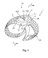
- FIG. 1 is a perspective view showing an embodiment when the timepiece of the invention equipped with the dial assembly of the invention is used for a wrist watch;
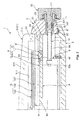
- FIG. 2 is a cross section diagram of line A-A in FIG. 1 .
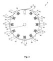
- FIG. 3 is a diagram (plan view) of the dial assembly in FIG. 1 seen from the arrow B direction;
- FIG. 4 is a perspective view of a decorative structure with the timepiece shown in FIG. 1 ;
- FIG. 5 is a cross section showing the assembly step order of the dial assembly of the invention.
- FIG. 6 is a cross section showing the assembly step order of the dial assembly of the invention.
- FIG. 7 is a cross section showing the assembly step order of the dial assembly of the invention.
- FIG. 8 is a cross section showing the assembly step order of the dial assembly of the invention.
- FIG. 9 is a cross section showing the assembly step order of the dial assembly of the invention.
- FIG. 1 is a perspective view showing an embodiment when the timepiece of the invention equipped with the dial assembly of the invention is used for a wrist watch.
- FIG. 2 is a cross section diagram of line A-A in FIG. 1 .
- FIG. 3 is a diagram (plan view) of the dial assembly in FIG. 1 seen from the arrow B direction.
- FIG. 4 is a perspective view of a decorative structure with the timepiece shown in FIG. 1 .
- FIG. 5 through FIG. 9 are cross section diagrams showing the assembly step order of the dial assembly of the invention. Following, according to the description circumstances, in FIG. 1 , FIG. 2 , and FIG. 4 through FIG. 9 , the top side is referred to as “top,” “above” or “front,” and the bottom side is referred to as “bottom,” “below,” or "back.”
- the wrist watch 1 shown in FIG. 1 and FIG. 2 (hereafter referred to simply as "watch") is equipped with a body (case) 2, a back cover 3, a cover glass (watch crystal) 5, and a band 20. Also, in sequence from the side at which the cover glass 5 is provided, the dial assembly 4 and the movement 9 are held in the internal space 50 of the watch 1 (space enclosed by the body 2, the back cover 3, and the cover glass 5). Also, the indicators (hands) 10 (the hour hand 101, the minute hand 102, and the second hand 103) are supported to be able to rotate on the movement 9, and are held within the internal space 50 of the watch 1 together with the movement 9. Following, we will describe the constitution of each part.
- the body 2 is constituted by an annular member.
- a rib 22 is formed projecting toward the center side on the inner circumference part 21 of the body 2.
- the rib 22 is formed in a ring shape along the circumference direction of the inner circumference part 21.
- a cover glass 5 is fixed to be air tight and liquid tight on this rib 22.
- this fixing method though not specifically restricted, an example that can be used is a method using adhesion (adhesion using an adhesive agent or solvent).
- the cover glass 5 is constituted from a cover glass main unit 51 forming a round disk shape and a leg part 52 formed projecting as an integral unit on the surface 511 of the back side of the cover glass main unit 51.
- the cover glass 5 is constituted from a transparent member.
- a transparent member means an item having transparency for which the visible light transmission rate is about 50 % or greater.
- transparent includes transparency with color (colored) in addition to colorless transparency.
- the constituent material of the cover glass 5 though not specifically restricted, for example inorganic glass or the like can be used.
- inorganic glass examples include soda lime glass, borosilicate glass, Hardrex (inorganic tempered glass), Clearex (non-reflective treated), spinel glass, sapphire glass or the like.
- material strength for example it is possible to reduce deformation and breaking due to pressure or impact, and to make it so that it does not scratch easily and also has good specularity.
- specularity As a result, the strength of the cover glass 5 itself is high, and it is possible to improve visibility.
- inorganic glass it is easily possible to perform adhesion using an adhesive agent, and thus, there is a wide range of selections of types of adhesive agent and adhesion method with which high adhesive strength can be obtained.
- the cover glass main unit 51 is a curved convex surface for which its front side surface 512 is curved in convex form.
- the overall watch 1 has excellent aesthetics and good design properties.
- a chamfer part 513 for which chamfering is implemented is formed on the edge part of the front side of the cover glass main unit 51. As a result, even if skin comes into contact with the edge part of the front side of the cover glass main unit 51, it is possible to reliably prevent the skin being injured, giving the cover glass a high level of safety.
- the leg part 52 forms a ring shape along the rib 22 of the body 2, and is a part that is fixed to that body 2.
- the inner diameter and the thickness (height) of the leg part 52 is not specifically restricted provided it is of a level for which it is possible to prevent interference with the indicator 10 of the cover glass 5.
- lugs 24 are provided as connector parts by which the band 20 is connected (see FIG. 1 ). The band 20 is used when wearing the watch 1 on the arm.
- a winding stem 11 is fit onto and fixed to the part between both lugs 24 of the outer circumference part 23 of the body 2.
- a shaft part 121 of a crown 12 is inserted to be able to rotate inside this winding stem 11. Furthermore, the shaft part 121 of the crown 12 is connected to the movement 9 via a shaft 13. Also, by doing a rotation operation of the crown 12, the rotation force is transmitted to the movement 9 via the shaft 13, and it is possible to adjust the position of the hour hand 101 and the minute hand 102.
- a groove 122 is formed on the outer circumference midway on the shaft part 121 of the crown 12, and ring shaped rubber packing (crown packing) 16 is fit into this groove 122.
- the rubber packing 16 is adhered to the inner circumference surface 111 of the winding stem 11, and is compressed between the inner circumference surface 111 and the groove 122 inner surface. With this constitution, it is possible to have between the crown 12 and the winding stem 11 sealed liquid tight to have a water proofing function. Note that when a rotation operation is done with the crown 12, the rubber packing 16 rotates together with the shaft part 121, and it can slide in the circumference direction while being adhered to the inner circumference surface of the winding stem 11.
- the back cover 3 is mounted by screwing or fitting, for example, on the back side of the body 2.
- the back cover 3 is constituted by a round disk shaped member.
- a recess 31 is formed along the circumference direction on the part of the top surface side (edge part) of the back cover 3.
- Packing 30 constituted by an elastic material is arranged on the recess 31. Then, when the back cover 3 is mounted on the body 2, the packing 30 is compressed, and it is possible to maintain an air tight and liquid tight state between the back cover 3 and the body 2.
- the constituent material for the body 2, the back cover 3, and the indicator 10 examples include various metal materials such as stainless steel, titanium, and titanium alloys (including alloys), and various types of resin materials (plastic materials) and the like. Among these, metal materials are preferably used because they are excellent in terms of aesthetic aspect and strength.
- the body 2, the back cover 3, and the indicator 10 can be constituted using the same materials as each other, and can also be constituted using different materials.
- a movement 9 is fixed to the back cover 3 via the fixing member 40.
- the movement 9 has a shaft 91 on which the hour hand 101, the minute hand 102, and the second hand 103 are rotationally supported.
- This movement 9 has a built in mechanism that drives (rotates) the hour hand 101, the minute hand 102, and the second hand 103 via the shaft 91 using power supplied from a button battery (not shown).
- This mechanism is not specifically restricted, but examples that can be used include a quartz oscillator as a time reference source, a semiconductor integrated circuit that generates a drive pulse for driving the watch based on the oscillating frequency of the quartz oscillator, a step motor for driving the indicator each second with the train wheel mechanism that receives this drive pulse, or an item equipped with the train wheel mechanism for transmitting the movement of the step motor to the indicator.
- the dial assembly 4 is placed on the movement 9.
- the dial assembly 4 has a dial 5 and eleven decorative structures 70.
- the dial 6 is constituted by a dial main unit 61 constituted with a member forming a plate shape (for example a round disk shape), and a display part (time scale) 63 arranged on the dial main unit 61.
- the dial main unit 61 is sandwiched between the movement 9 and the rib 22 of the body 2. As a result, the dial 6 (dial assembly 4) is reliably fixed, and slipping during use of the watch is reliably prevented.
- an insertion hole 62 in which the shaft 91 of the movement 9 is inserted is formed.
- a strip of paper shaped display part 63 that displays the time by the indication of the hour hand 101, the minute hand 102, and the second hand 103.
- the fixing method for this examples include a method using adhesion (adhesion using an adhesive agent or solvent), a method using fusion (thermal fusion, high frequency fusion, ultrasonic fusion and the like), a method using fitting, a method using crimping or the like.
- the display part 63 is arranged at a position corresponding to "12" of the numbers 1 to 12 expressing the time. The time can also be confirmed by the position indicated by the display part 63 respectively with the hour hand 101, the minute hand 102, and the second hand 103.
- fixing parts 64 for fixing the respective decorative structures 70 to the positions corresponding to "1" to "11” of the numbers 1 to 12 expressing the time of the dial main unit 61 (dial 6) are provided.
- Each fixing part 64 is respectively constituted by a through hole that pierces the dial main unit 61 in the thickness direction. Also, by the decorative structure 70 being inserted in the fixing part 64 constituted by this through hole, that decorative structure 70 is fitted and reliably fixed (see FIG. 8 and FIG. 9 ). It is possible to confirm the time by the respective position indicated respectively by the hour hand 101, the minute hand 102, and the second hand 103 at any of the decorative structures 70.
- constituent material for dial main unit 61 and the display part 63 examples include various metal materials such as stainless steel, titanium, and titanium alloys (including alloys), and various types of resin materials (plastic materials) and the like. Among these, metal materials are preferably used because they are excellent in terms of aesthetic aspect and strength.
- Each decorative structure 70 has the same constitution, so hereafter, we will give a representative description of one decorative structure 70.
- the decorative structure 70 is constituted by a decorative member 7 and a support member 8.
- the decorative member 7 is a jewel which can be visually recognized via the cover glass 5 via the front side of the dial 6.
- examples that can be used include diamonds, sapphires, rubies, and the like.
- this decorative member 7 can be divided into a multifaceted formed part 71 and a back side cone shaped part 72 (or pyramid shaped part).
- a plurality of flat planes are formed on the multifaceted formed part 71, and each plane faces a different direction from the others.
- the multifaceted formed part 71 has a flat plane 711 facing upward and forming an octagon shape, and eight fan-shaped planes 712, 713, 714, 715, 716, 717, 718, and 719 formed tilting in mutually different directions in relation to a normal vector of the plane 711 on the periphery of the plane 711.
- the cone shaped part 72 is formed so that its center axis is parallel to the normal vector of the plane 711.
- This kind of decorative member 7 is supported on the dial main unit 61 of the dial 6 via the support member 8.
- the support member 8 is constituted with a flat block unit made of metal.
- the metal constituting the support member 8 though not specifically restricted, examples that can be used include various metal materials such as stainless steel, titanium, and titanium alloys (including alloys).
- a recess part 82 is formed at the center part of the front side surface 81 of the support member 8.
- the recess part 82 forms a shape corresponding to the external shape of the cone shaped part 72 of the decorative member 7, specifically, it forms a mortar shape.
- the cone shaped part 72 of the decorative member 7 is held in this recess part 82.
- the part that is not held in the recess part 82 of the decorative member 7, specifically, the multifaceted formed part 71 is exposed, and can be visually recognized via the cover glass 5.
- a through hole 821 is formed on the bottom part of the recess part 82.
- the vertex 721 of the cone shaped part 72 is positioned inside this through hole 821.
- claw parts 841, 842, 843, and 844 are formed projecting on the front side surface 81 of the support member 8.
- the claw parts 841 to 844 are arranged at different positions from the recess part 82, specifically, at equal gaps along the periphery of the recess part 82. Also, the claw parts 841 to 844 respectively become gradually wider with the width facing downward. Then, the claw parts 841 to 844 can be bent by the base part 845 which is the boundary part with the front side surface 81 (see FIG. 6 and FIG. 7 ).
- the bent base part 845 is plastically deformed and maintains that bent state.
- the claw parts 841 to 844 bent in this way by the base part 845 are respectively able to engage with the decorative member 7 held in the recess part 82 (see FIG. 7 to FIG. 9 ).
- the claw part 841 is engaged with the plane 712 of the multifaceted formed part 71 of the decorative member 7
- the claw part 842 is engaged with the plane 714 of the multifaceted formed part 71
- the claw part 843 is engaged with the plane 716 of the multifaceted formed part 71
- the claw part 844 is engaged with the plane 718 of the multifaceted formed part 71.
- the claw parts 841 to 844 each have a portion that projects further upward than the plane 711 of the multifaceted formed part 71 of the decorative member 6 when in the state before being bent, and positioned below the plane 711 in the bent state (see FIG. 6 to FIG. 9 ). Also, engaging parts (projecting parts) 851, 852, 853, and 854 are formed projecting at the bottom part of the side surface 86 (comer) of the support member 8.
- the engaging part 851 is arranged at the outside of the claw part 841
- the engaging part 852 is arranged at the outside of the claw part 842
- the engaging part 853 is arranged at the outside of the claw part 843
- the engaging part 854 is arranged at the outside of the claw part 844.
- a step part 641 for which the inner diameter changes in steps is formed respectively on the edge part of each fixing part 64 of the dial 6.
- the decorative structure 70 support member 8
- the engaging parts 851 to 854 are engaged in the step part 641.
- the insertion depth of the decorative structure 70 in relation to the fixing part 64 is regulated, and thus, it is possible to reliably prevent the insertion of the decorative structure 70 from being excessive and the insertion of the decorative structure 70 from being insufficient.
- the decorative structure 70 inserted in the fixing part 64 of the dial 6 has a portion (the top part) projecting from the front side surface 611 of the dial 6. Following, that projecting part is called the "projecting part 701."
- the decorative structure 70 is inserted in the fixing part 64 from the back side and fixed.
- the amount of the overall thickness amount of the dial main unit 61, of the overall thickness (height) of the decorative structure 70 it is possible to suppress to the extent possible the projection volume (projection height) of the projecting part 701, specifically, the projection of the decorative member 7 from the front side surface 611 of the dial 6.
- the claw parts 841 to 844 are respectively bent by the base part 845.
- the claw part 841 engages with the plane 712 of the decorative member 7
- the claw part 842 engages with the plane 714 of the decorative member 7
- the claw part 843 engages with the plane 716 of the decorative member 7
- the claw part 844 engages with the plane 718 of the decorative member 7.
- each of the assembled decorative structures 70 is inserted from the back side of the fixing part 64 of the dial 6. As shown in FIG. 9 , the degree of insertion is until the engaging parts 851 to 854 of the support member 8 contact the step part 641 of the fixing part 64. As a result, a dial assembly 4 is obtained for which the projection volumes of the projecting parts 701 of each decorative structure 70 are all the same (uniform).
- dial assembly and the watch of the invention using the embodiments in the drawings, but the invention is not limited to this, and each part constituting the dial assembly and the watch can be substituted with any constitution for which the same function can be exhibited. Also, any structural element can also be added. Also, the number of decorative structures arranged with the dial assembly was eleven with this embodiment, but the invention is not limited to this, and for example can be one, two, three, four, five, six, seven, eight, nine, ten, or twelve.
- the watch was constituted with the minute hand and the second hand passing through the front side of the projecting part of the decorative structure, but the invention is not limited to this, and it is also possible to constitute this with all the indicators of the hour hand, minute hand, and second hand passing through the front side of the projecting part of the decorative structure.
Landscapes
- Physics & Mathematics (AREA)
- General Physics & Mathematics (AREA)
- Electromechanical Clocks (AREA)
- Adornments (AREA)
Applications Claiming Priority (1)
| Application Number | Priority Date | Filing Date | Title |
|---|---|---|---|
| JP2011205222A JP2013068430A (ja) | 2011-09-20 | 2011-09-20 | 文字板組立体および時計 |
Publications (2)
| Publication Number | Publication Date |
|---|---|
| EP2573628A2 true EP2573628A2 (fr) | 2013-03-27 |
| EP2573628A3 EP2573628A3 (fr) | 2017-02-01 |
Family
ID=47080197
Family Applications (1)
| Application Number | Title | Priority Date | Filing Date |
|---|---|---|---|
| EP12184817.0A Withdrawn EP2573628A3 (fr) | 2011-09-20 | 2012-09-18 | Cadran de montre et montre |
Country Status (4)
| Country | Link |
|---|---|
| US (1) | US20130070573A1 (fr) |
| EP (1) | EP2573628A3 (fr) |
| JP (1) | JP2013068430A (fr) |
| CN (1) | CN103019083A (fr) |
Cited By (2)
| Publication number | Priority date | Publication date | Assignee | Title |
|---|---|---|---|---|
| CN106506745A (zh) * | 2016-11-30 | 2017-03-15 | 深圳天珑无线科技有限公司 | 电子设备以及在电子设备中镶嵌装饰件的方法 |
| EP3378346A1 (fr) * | 2017-03-21 | 2018-09-26 | Omega SA | Pierre et son procédé de réalisation |
Families Citing this family (29)
| Publication number | Priority date | Publication date | Assignee | Title |
|---|---|---|---|---|
| ITMI20131343A1 (it) * | 2013-08-05 | 2015-02-06 | Dolce & Gabbana Srl | Sistema di fissaggio di gemme al quadrante di un orologio e orologio dotato di tale sistema di fissaggio delle gemme |
| EP3042271B1 (fr) * | 2013-09-03 | 2020-03-18 | Apple Inc. | Manipulations d'un objet sur une interface utilisateur |
| US12287962B2 (en) | 2013-09-03 | 2025-04-29 | Apple Inc. | User interface for manipulating user interface objects |
| US11068128B2 (en) | 2013-09-03 | 2021-07-20 | Apple Inc. | User interface object manipulations in a user interface |
| US10503388B2 (en) | 2013-09-03 | 2019-12-10 | Apple Inc. | Crown input for a wearable electronic device |
| HK1196748A2 (en) * | 2013-10-29 | 2014-12-19 | Chung Nam Watch Company Limited | A wearable article |
| EP2901883A1 (fr) * | 2014-01-31 | 2015-08-05 | Cartier Création Studio S.A. | Pierre montée sur un élément ressort |
| EP4036685A1 (fr) | 2014-06-27 | 2022-08-03 | Apple Inc. | Interface utilisateur de taille réduite |
| WO2016036510A1 (fr) | 2014-09-02 | 2016-03-10 | Apple Inc. | Interface utilisateur de musique |
| TWI676127B (zh) | 2014-09-02 | 2019-11-01 | 美商蘋果公司 | 關於電子郵件使用者介面之方法、系統、電子器件及電腦可讀儲存媒體 |
| US10073590B2 (en) | 2014-09-02 | 2018-09-11 | Apple Inc. | Reduced size user interface |
| TW201610758A (zh) | 2014-09-02 | 2016-03-16 | 蘋果公司 | 按鈕功能性 |
| USD726055S1 (en) * | 2014-11-04 | 2015-04-07 | Graff Diamonds Sa | Watch dial |
| USD764338S1 (en) * | 2015-02-26 | 2016-08-23 | Tudor Watch U.S.A., Llc | Watch hands |
| CA164040S (en) * | 2015-02-26 | 2017-02-17 | Rolex Sa | Watch dial |
| CN105988358B (zh) * | 2015-02-26 | 2019-10-01 | 精工爱普生株式会社 | 带旋转表圈的钟表 |
| CA164158S (fr) * | 2015-03-05 | 2016-03-29 | Winston Harry Sa | Boîte de montre |
| JP1547576S (fr) * | 2015-03-13 | 2016-04-11 | ||
| DE102015207049A1 (de) * | 2015-04-17 | 2016-10-20 | Levitation AG | Uhrglas mit mindestens einem Schmuckstein |
| USD852664S1 (en) * | 2016-10-31 | 2019-07-02 | Realization Desal Ag | Watch face |
| CN106790786A (zh) * | 2016-11-30 | 2017-05-31 | 深圳天珑无线科技有限公司 | 电子设备以及在电子设备中镶嵌装饰件的方法 |
| TWD189644S (zh) * | 2017-03-03 | 2018-04-11 | 哈利溫士頓公司 | 錶殼 |
| EP3502790A1 (fr) * | 2017-12-21 | 2019-06-26 | ETA SA Manufacture Horlogère Suisse | Piece d'horlogerie comportant un dispositif de fixation d'un cadran |
| CN107957673A (zh) * | 2018-01-18 | 2018-04-24 | 于威 | 多样装饰性的手表 |
| US11435830B2 (en) | 2018-09-11 | 2022-09-06 | Apple Inc. | Content-based tactile outputs |
| US11687035B2 (en) * | 2019-07-30 | 2023-06-27 | Citizen Watch Co., Ltd. | Display panel |
| EP3771948B1 (fr) | 2019-07-31 | 2025-03-19 | Omega SA | Cadran pour piece d`horlogerie |
| CN111221240A (zh) * | 2020-03-11 | 2020-06-02 | 励创海丝(福建)钟表产业工业设计研究有限公司 | 一种指针弯折式时钟 |
| CN114995091B (zh) * | 2020-12-28 | 2024-07-05 | 深圳西普尼精密科技股份有限公司 | 具有无遮挡表针结构的手表 |
Citations (1)
| Publication number | Priority date | Publication date | Assignee | Title |
|---|---|---|---|---|
| JP2000275360A (ja) | 1999-03-25 | 2000-10-06 | Kawaguchiko Seimitsu Co Ltd | 表示板の表示部品取付構造 |
Family Cites Families (12)
| Publication number | Priority date | Publication date | Assignee | Title |
|---|---|---|---|---|
| US2606418A (en) * | 1948-02-24 | 1952-08-12 | Fluckiger & Cie | Indicia retaining means for timepiece dials |
| JPS5816583U (ja) * | 1981-07-24 | 1983-02-01 | セイコーインスツルメンツ株式会社 | 時計用表示板 |
| CH680328B5 (fr) * | 1990-12-04 | 1993-02-15 | Ebauchesfabrik Eta Ag | |
| CH684814B5 (fr) * | 1993-01-25 | 1995-07-14 | Hugues Jolidon Antoine Andelfi | Pièce d'horlogerie pourvue d'un tour d'heures à présentation modifiable. |
| FR2757353B1 (fr) * | 1997-03-18 | 1999-02-26 | Chopard Holding | Article comportant au moins un element decoratif mobile |
| JP2000304876A (ja) * | 1999-04-23 | 2000-11-02 | Seiko Corp | 時計文字板とその製造方法 |
| EP1640822B1 (fr) * | 2004-09-22 | 2012-08-01 | Asulab S.A. | Cadran émaillé multi-étages |
| JP2006208207A (ja) * | 2005-01-28 | 2006-08-10 | Citizen Seimitsu Co Ltd | 貴石風指標部品を備えた表示板 |
| JP2008076258A (ja) * | 2006-09-22 | 2008-04-03 | Citizen Holdings Co Ltd | 時計用表示板 |
| CH702127B1 (fr) * | 2007-05-25 | 2011-05-13 | Paul Hartzband | Pièce d'horlogerie munie d'un tour d'heures variable. |
| CN201886286U (zh) * | 2010-11-16 | 2011-06-29 | 瑞士亿科有限公司 | 刻度旋转装置及钟表 |
| EP2653939B1 (fr) * | 2012-04-20 | 2017-08-30 | ETA SA Manufacture Horlogère Suisse | Cadran pour pièce d'horlogerie |
-
2011
- 2011-09-20 JP JP2011205222A patent/JP2013068430A/ja not_active Withdrawn
-
2012
- 2012-09-04 CN CN2012103234223A patent/CN103019083A/zh active Pending
- 2012-09-04 US US13/602,803 patent/US20130070573A1/en not_active Abandoned
- 2012-09-18 EP EP12184817.0A patent/EP2573628A3/fr not_active Withdrawn
Patent Citations (1)
| Publication number | Priority date | Publication date | Assignee | Title |
|---|---|---|---|---|
| JP2000275360A (ja) | 1999-03-25 | 2000-10-06 | Kawaguchiko Seimitsu Co Ltd | 表示板の表示部品取付構造 |
Cited By (3)
| Publication number | Priority date | Publication date | Assignee | Title |
|---|---|---|---|---|
| CN106506745A (zh) * | 2016-11-30 | 2017-03-15 | 深圳天珑无线科技有限公司 | 电子设备以及在电子设备中镶嵌装饰件的方法 |
| EP3378346A1 (fr) * | 2017-03-21 | 2018-09-26 | Omega SA | Pierre et son procédé de réalisation |
| US11000102B2 (en) | 2017-03-21 | 2021-05-11 | Omega Sa | Gemstone and method for producing the same |
Also Published As
| Publication number | Publication date |
|---|---|
| CN103019083A (zh) | 2013-04-03 |
| US20130070573A1 (en) | 2013-03-21 |
| JP2013068430A (ja) | 2013-04-18 |
| EP2573628A3 (fr) | 2017-02-01 |
Similar Documents
| Publication | Publication Date | Title |
|---|---|---|
| EP2573628A2 (fr) | Cadran de montre et montre | |
| US8976630B2 (en) | Dial assembly and timepiece | |
| US6275450B1 (en) | Timepiece | |
| JP5824969B2 (ja) | カバーガラスおよび時計 | |
| US4241442A (en) | Timepiece with shaped components | |
| US20050185517A1 (en) | Oval shaped timepieces and stem arrangement for watches | |
| US12422780B2 (en) | Timepiece | |
| US4043116A (en) | Timepiece comprising a flat display device exposed through an opening in a case | |
| US20100278018A1 (en) | Timepiece having an automatic winding mechanism | |
| JP6003027B2 (ja) | 文字板構造及び腕時計 | |
| JP7626156B2 (ja) | 時計 | |
| US20170045860A1 (en) | Dual Time Watch and Watch Case Assembly | |
| JP2006053150A (ja) | 光学効果を有する時計用ガラスとこの様なガラスを具備した時計。 | |
| GB2162663A (en) | Timepiece | |
| CN111722516B (zh) | 世界时手表的表盘 | |
| US6270250B1 (en) | Watch having an opening | |
| US4999822A (en) | Dial face for clock or watch | |
| US11687033B2 (en) | Self-winding watch | |
| CN212009294U (zh) | 手表 | |
| CN207488705U (zh) | 轨道式立体日历手表以及机械表 | |
| US20240004347A1 (en) | Timepiece | |
| JP3250221B2 (ja) | 計時装置 | |
| CN210181397U (zh) | 一种单指针指示系统以及手表 | |
| JPS6166179A (ja) | 時計 | |
| JPWO1999018479A1 (ja) | 計時装置 |
Legal Events
| Date | Code | Title | Description |
|---|---|---|---|
| PUAI | Public reference made under article 153(3) epc to a published international application that has entered the european phase |
Free format text: ORIGINAL CODE: 0009012 |
|
| AK | Designated contracting states |
Kind code of ref document: A2 Designated state(s): AL AT BE BG CH CY CZ DE DK EE ES FI FR GB GR HR HU IE IS IT LI LT LU LV MC MK MT NL NO PL PT RO RS SE SI SK SM TR |
|
| AX | Request for extension of the european patent |
Extension state: BA ME |
|
| PUAL | Search report despatched |
Free format text: ORIGINAL CODE: 0009013 |
|
| AK | Designated contracting states |
Kind code of ref document: A3 Designated state(s): AL AT BE BG CH CY CZ DE DK EE ES FI FR GB GR HR HU IE IS IT LI LT LU LV MC MK MT NL NO PL PT RO RS SE SI SK SM TR |
|
| AX | Request for extension of the european patent |
Extension state: BA ME |
|
| RIC1 | Information provided on ipc code assigned before grant |
Ipc: G04B 47/04 20060101ALI20161223BHEP Ipc: G04B 19/10 20060101AFI20161223BHEP |
|
| STAA | Information on the status of an ep patent application or granted ep patent |
Free format text: STATUS: THE APPLICATION IS DEEMED TO BE WITHDRAWN |
|
| 18D | Application deemed to be withdrawn |
Effective date: 20170802 |