EP2573765B1 - Codeur et décodeur audio - Google Patents
Codeur et décodeur audio Download PDFInfo
- Publication number
- EP2573765B1 EP2573765B1 EP12195829.2A EP12195829A EP2573765B1 EP 2573765 B1 EP2573765 B1 EP 2573765B1 EP 12195829 A EP12195829 A EP 12195829A EP 2573765 B1 EP2573765 B1 EP 2573765B1
- Authority
- EP
- European Patent Office
- Prior art keywords
- mdct
- frames
- lpc
- gain
- frame
- Prior art date
- Legal status (The legal status is an assumption and is not a legal conclusion. Google has not performed a legal analysis and makes no representation as to the accuracy of the status listed.)
- Active
Links
Images


Classifications
-
- G—PHYSICS
- G10—MUSICAL INSTRUMENTS; ACOUSTICS
- G10L—SPEECH ANALYSIS TECHNIQUES OR SPEECH SYNTHESIS; SPEECH RECOGNITION; SPEECH OR VOICE PROCESSING TECHNIQUES; SPEECH OR AUDIO CODING OR DECODING
- G10L19/00—Speech or audio signals analysis-synthesis techniques for redundancy reduction, e.g. in vocoders; Coding or decoding of speech or audio signals, using source filter models or psychoacoustic analysis
- G10L19/04—Speech or audio signals analysis-synthesis techniques for redundancy reduction, e.g. in vocoders; Coding or decoding of speech or audio signals, using source filter models or psychoacoustic analysis using predictive techniques
- G10L19/26—Pre-filtering or post-filtering
-
- G—PHYSICS
- G10—MUSICAL INSTRUMENTS; ACOUSTICS
- G10L—SPEECH ANALYSIS TECHNIQUES OR SPEECH SYNTHESIS; SPEECH RECOGNITION; SPEECH OR VOICE PROCESSING TECHNIQUES; SPEECH OR AUDIO CODING OR DECODING
- G10L19/00—Speech or audio signals analysis-synthesis techniques for redundancy reduction, e.g. in vocoders; Coding or decoding of speech or audio signals, using source filter models or psychoacoustic analysis
- G10L19/008—Multichannel audio signal coding or decoding using interchannel correlation to reduce redundancy, e.g. joint-stereo, intensity-coding or matrixing
-
- G—PHYSICS
- G10—MUSICAL INSTRUMENTS; ACOUSTICS
- G10L—SPEECH ANALYSIS TECHNIQUES OR SPEECH SYNTHESIS; SPEECH RECOGNITION; SPEECH OR VOICE PROCESSING TECHNIQUES; SPEECH OR AUDIO CODING OR DECODING
- G10L19/00—Speech or audio signals analysis-synthesis techniques for redundancy reduction, e.g. in vocoders; Coding or decoding of speech or audio signals, using source filter models or psychoacoustic analysis
- G10L19/02—Speech or audio signals analysis-synthesis techniques for redundancy reduction, e.g. in vocoders; Coding or decoding of speech or audio signals, using source filter models or psychoacoustic analysis using spectral analysis, e.g. transform vocoders or subband vocoders
- G10L19/0212—Speech or audio signals analysis-synthesis techniques for redundancy reduction, e.g. in vocoders; Coding or decoding of speech or audio signals, using source filter models or psychoacoustic analysis using spectral analysis, e.g. transform vocoders or subband vocoders using orthogonal transformation
-
- G—PHYSICS
- G10—MUSICAL INSTRUMENTS; ACOUSTICS
- G10L—SPEECH ANALYSIS TECHNIQUES OR SPEECH SYNTHESIS; SPEECH RECOGNITION; SPEECH OR VOICE PROCESSING TECHNIQUES; SPEECH OR AUDIO CODING OR DECODING
- G10L19/00—Speech or audio signals analysis-synthesis techniques for redundancy reduction, e.g. in vocoders; Coding or decoding of speech or audio signals, using source filter models or psychoacoustic analysis
- G10L19/02—Speech or audio signals analysis-synthesis techniques for redundancy reduction, e.g. in vocoders; Coding or decoding of speech or audio signals, using source filter models or psychoacoustic analysis using spectral analysis, e.g. transform vocoders or subband vocoders
- G10L19/032—Quantisation or dequantisation of spectral components
- G10L19/035—Scalar quantisation
Definitions
- the present invention relates to coding of audio signals, and in particular to the coding of any audio signal not limited to either speech, music or a combination thereof.
- Sean A Ramprashad "The Multimode Transform Predictive Coding Paradigm", IEEE Transactions on Speech and Audio Processing, vol. 11, no. 2, 1 March 2003 , describes a multimode transform predictive coding scheme.
- Sean A Ramprashad "High Quality Embedded Wideband Speech Coding Using an Inherently Layered Coding Paradigm", 2000 IEEE International Conference on Acoustics, Istanbul, Turkey, June 5-9, 2000, pages 1145-1148 , describes a coding strategy for wideband signals.
- US 6,826,526 B1 describes an audio signal coding method.
- the present invention relates to efficiently coding arbitrary audio signals at a quality level equal or better than that of a system specifically tailored to a specific signal.
- the present invention is directed at audio codec algorithms that contain both a linear prediction coding (LPC) and a transform coder part.
- LPC linear prediction coding
- the present invention further relates to efficiently coding of scalefactors in the transform coding part of an audio encoder by exploiting the presence of LPC data.
- the present invention further relates to an encoder for encoding audio signals and generating a bitstream, and a decoder for decoding the bitstream and generating a reconstructed audio signal that is perceptually indistinguishable from the input audio signal.
- a first aspect of the present invention relates to an audio coding system according to claim 1.
- Another aspect of the invention relates to an audio decoder according to claim 7.
- the application further discloses an audio encoding method according to claim 8 and an audio decoding method according to claim 9.
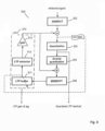
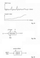
- Fig. 1 an encoder 101 and a decoder 102 are visualized.
- the encoder 101 takes the time-domain input signal and produces a bitstream 103 subsequently sent to the decoder 102.
- the decoder 102 produces an output wave-form based on the received bitstream 103.
- the output signal psycho-acoustically resembles the original input signal.
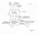
- Fig. 2 a preferred embodiment not according to the claimed invention of the encoder 200 and the decoders 210 are illustrated.
- the input signal in the encoder 200 is passed through a LPC (Linear Prediction Coding) module 201 that generates a whitened residual signal for an LPC frame having a first frame length, and the corresponding linear prediction parameters. Additionally, gain normalization may be included in the LPC module 201.
- the residual signal from the LPC is transformed into the frequency domain by an MDCT (Modified Discrete Cosine Transform) module 202 operating on a second variable frame length.
- an LTP (Long Term Prediction) module 205 is included. LTP will be elaborated on in a further example.
- the MDCT lines are quantized 203 and also de-quantized 204 in order to feed a LTP buffer with a copy of the decoded output as will be available to the decoder 210. Due to the quantization distortion, this copy is called reconstruction of the respective input signal.
- the decoder 210 is depicted.
- the decoder 210 takes the quantized MDCT lines, de-quantizes 211 them, adds the contribution from the LTP module 214, and does an inverse MDCT transform 212, followed by an LPC synthesis filter 213.
- the MDCT frame is the only basic unit for coding, although the LPC has its own (and in one embodiment constant) frame size and LPC parameters are coded, too.
- the embodiment starts from a transform coder and introduces fundamental prediction and shaping modules from a speech coder.
- the MDCT frame size is variable and is adapted to a block of the input signal by determining the optimal MDCT window sequence for the entire block by minimizing a simplistic perceptual entropy cost function. This allows scaling to maintain optimal time/frequency control. Further, the proposed unified structure avoids switched or layered combinations of different coding paradigms.
- the whitened signal as output from the LPC module 201 in the encoder of Fig. 2 is input to the MDCT filterbank 302.
- the MDCT analysis may optionally be a time-warped MDCT analysis that ensures that the pitch of the signal (if the signal is periodic with a well-defined pitch) is constant over the MDCT transform window.
- the LTP module 310 is outlined in more detail. It comprises a LTP buffer 311 holding reconstructed time-domain samples of the previous output signal segments.
- a LTP extractor 312 finds the best matching segment in the LTP buffer 311 given the current input segment. A suitable gain value is applied to this segment by gain unit 313 before it is subtracted from the segment currently being input to the quantizer 303.
- the LTP extractor 312 also transforms the chosen signal segment to the MDCT-domain.
- the LTP extractor 312 searches for the best gain and lag values that minimize an error function in the perceptual domain when combining the reconstructed previous output signal segment with the transformed MDCT-domain input frame.
- a mean squared error (MSE) function between the transformed reconstructed segment from the LTP module 310 and the transformed input frame (i.e. the residual signal after the subtraction) is optimized.
- This optimization may be performed in a perceptual domain where frequency components (i.e. MDCT lines) are weighted according to their perceptual importance.
- the LTP module 310 operates in MDCT frame units and the encoder300 considers one MDCT frame residual at a time, for instance for quantization in the quantization module 303.
- the lag and gain search may be performed in a perceptual domain.
- the LTP may be frequency selective, i.e. adapting the gain and/or lag over frequency.
- An inverse quantization unit 304 and an inverse MDCT unit 306 are depicted.
- the MDCT may be time-warped as explained later.
- Fig. 4 another embodiment of the encoder 400 is illustrated.
- the LPC analysis 401 is included for clarification.
- a DCT-IV transform 414 used to transform a selected signal segment to the MDCT-domain is shown.
- several ways of calculating the minimum error for the LTP segment selection are illustrated.
- the minimization of the residual signal as shown in Fig. 4 (identified as LTP2 in Fig. 4 )
- the minimization of the difference between the transformed input signal and the de-quantized MDCT-domain signal before being inversely transformed to a reconstructed time-domain signal for storage in the LTP buffer 411 is illustrated (indicated as LTP3).
- Minimization of this MSE function will direct the LTP contribution towards an optimal (as possible) similarity of transformed input signal and reconstructed input signal for storage in the LTP buffer 411.
- Another alternative error function (indicated as LTP1) is based on the difference of these signals in the time-domain.
- LTP1 Another alternative error function
- the MSE is advantageously calculated based on the MDCT frame size, which may be different from the LPC frame size.
- the quantizer and de-quantizer blocks are replaced by the spectrum encoding block 403 and the spectrum decoding blocks 404 ("Spec enc" and "Spec dec") that may contain additional modules apart from quantization as will be outlined in Fig 6 .
- the MDCT and inverse MDCT may be time-warped (WMDCT, IWMDCT).
- a proposed decoder 500 is illustrated.
- the spectrum data from the received bitstream is inversely quantized 511 and added with a LTP contribution provided by a LTP extractor from a LTP buffer 515.
- LTP extractor 516 and LTP gain unit 517 in the decoder 500 are illustrated, too.
- the summed MDCT lines are synthesized to the time-domain by a MDCT synthesis block, and the time-domain signal is spectrally shaped by a LPC synthesis filter 513.
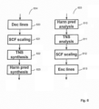
- the "Spec dec” and “Spec enc” blocks 403, 404 of Fig. 4 are described in more detail.
- the "Spec enc” block 603 illustrated to the right in the figure comprises in an embodiment an Harmonic Prediction analysis module 610, a TNS analysis (Temporal Noise Shaping) module 611, followed by a scale-factor scaling module 612 of the MDCT lines, and finally quantization and encoding of the lines in a Enc lines module 613.
- the decoder "Spec Dec” block 604 illustrated to the left in the figure does the inverse process, i.e. the received MDCT lines are de-quantized in a Dec lines module 620 and the scaling is un-done by a scalefactor (SCF) scaling module 621.
- SCF scalefactor
- Fig. 7 a very general illustration of the coding system is outlined.
- the exemplary encoder takes the input signal and produces a bitstream containing, among other data:
- the decoder reads the provided bitstream and produces an audio output signal, psycho-acoustically resembling the original signal.
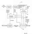
- Fig. 7a is another illustration of aspects of an encoder 700 according to an embodiment not according to the claimed invention.
- the encoder 700 comprises an LPC module 701, a MDCT module 704, a LTP module 705 (shown only simplified), a quantization module 703 and an inverse quantization module 704 for feeding back reconstructed signals to the LTP module 705. Further provided are a pitch estimation module 750 for estimating the pitch of the input signal, and a window sequence determination module 751 for determining the optimal MDCT window sequence for a larger block of the input signal (e.g. 1 second).
- the MDCT window sequence is determined based on an open-loop approach where sequence of MDCT window size candidates is determined that minimizes a coding cost function, e.g. a simplistic perceptual entropy.
- the contribution of the LTP module 705 to the coding cost function that is minimized by the window sequence determination module 751 may optionally be considered when searching for the optimal MDCT window sequence.
- the best long term prediction contribution to the MDCT frame corresponding to the window size candidate is determined, and the respective coding cost is estimated.
- short MDCT frame sizes are more appropriate for speech input while long transform windows having a fine spectral resolution are preferred for audio signals.
- Perceptual weights or a perceptual weighting function are determined based on the LPC parameters as calculated by the LPC module 701, which will be explained in more detail below.
- the perceptual weights are supplied to the LTP module 705 and the quantization module 703, both operating in the MDCT-domain, for weighting error or distortion contributions of frequency components according to their respective perceptual importance.
- Fig. 7a further illustrates which coding parameters are transmitted to the decoder, preferably by an appropriate coding scheme as will be discussed later.
- the LP module filters the input signal so that the spectral shape of the signal is removed, and the subsequent output of the LP module is a spectrally flat signal.
- This is advantageous for the operation of, e.g., the LTP.
- other parts of the codec operating on the spectrally flat signal may benefit from knowing what the spectral shape of the original signal was prior to LP filtering. Since the encoder modules, after the filtering, operate on the MDCT transform of the spectrally flat signal, the spectral shape of the original signal prior to LP filtering can, if needed, be re-imposed on the MDCT representation of the spectrally flat signal by mapping the transfer function of the used LP filter (i.e.
- the LP module omits the actual filtering, and only estimates a transfer function that is subsequently mapped to a gain curve which is imposed on the MDCT representation of the signal, thus removing the need for time domain filtering of the input signal.
- an MDCT-based transform coder is operated using a flexible window segmentation, on a LPC whitened signal.
- a LPC whitened signal
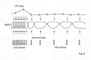
- an exemplary MDCT window sequence is given, along with the windowing of the LPC.
- the LPC operates on a constant frame-size (e.g. 20 ms), while the MDCT operates on a variable window sequence (e.g. 4 to 128 ms). This allows for choosing the optimal window length for the LPC and the optimal window sequence for the MDCT independently.
- LPC data in particular the LPC parameters
- MDCT data in particular the MDCT lines
- the downward arrows in the figure symbolize LPC data that is interpolated between the LPC frames (circles) so as to match corresponding MDCT frames.
- LPC-generated perceptual weighting function is interpolated for time instances as determined by the MDCT window sequence.
- the upward arrows symbolize refinement data (i.e. control data) used for the MDCT lines coding.
- refinement data i.e. control data
- the solid vs dashed lines represent which data is the most "important" data for the MDCT lines coding given a certain quantizer.
- the double downward arrows symbolize the codec spectral lines.
- LPC and MDCT data in the encoder may be exploited, for instance, to reduce the bit requirements of encoding MDCT scalefactors by taking into account a perceptual masking curve estimated from the LPC parameters.
- LPC derived perceptual weighting may be used when determining quantization distortion.
- the quantizer operates in two modes and generates two types of frames (ECQ frames and AAC frames) depending on the frame size of received data, i.e. corresponding to the MDCT frame or window size.
- Fig. 11 illustrates a preferred embodiment of mapping the constant rate LPC parameters to adaptive MDCT window sequence data.
- a LPC mapping module 1100 receives the LPC parameters according to the LPC update rate.
- the LPC mapping module 1100 receives information on the MDCT window sequence. It then generates a LPC-to-MDCT mapping, e.g., for mapping LPC-based psycho-acoustic data to respective MDCT frames generated at the variable MDCT frame rate.
- the LPC mapping module interpolates LPC polynomials or related data for time instances corresponding to MDCT frames for usage, e.g., as perceptual weights in LTP module or quantizer. Now, specifics of the LPC-based perceptual model are discussed by referring to Fig.
- the LPC module 901 is in an embodiment not according to the claimed invention adapted to produce a white output signal, by using linear prediction of, e.g., order 16 for a 16 kHz sampling rate signal.
- the output from the LPC module 201 in Fig. 2 is the residual after LPC parameter estimation and filtering.
- the estimated LPC polynomial A(z) as schematically visualized in the lower left of Fig. 9 , may be chirped by a bandwidth expansion factor, and also tilted by modifying the first reflection coefficient of the corresponding LPC polynomial. Chirping expands the bandwidth of peaks in the LPC transfer function by moving the poles of the polynomial inwards into the unit circle, thus resulting in softer peaks.
- Tilting allows making the LPC transfer function flatter in order to balance the influence of lower and higher frequencies. These modifications strive to generate a perceptual masking curve A'(z) from the estimated LPC parameters that will be available on both the encoder and the decoder side of the system. Details to the manipulation of the LPC polynomial are presented in Fig. 12 below.
- the MDCT coding operating on the LPC residual has, in one implementation of the invention, scalefactors to control the resolution of the quantizer or the quantization step sizes (and, thus, the noise introduced by quantization).
- scalefactors are estimated by a scalefactor estimation module 960 on the original input signal.
- the scalefactors are derived from a perceptual masking threshold curve estimated from the original signal.
- a separate frequency transform (having possibly a different frequency resolution) may be used to determine the masking threshold curve, but this is not always necessary.
- the masking threshold curve is estimated from the MDCT lines generated by the transformation module.
- the bottom right part of Fig. 9 schematically illustrates scalefactors generated by the scalefactor estimation module 960 to control quantization so that the introduced quantization noise is limited to inaudible distortions.
- a whitened signal is transformed to the MDCT-domain.
- this signal has a white spectrum, it is not well suited to derive a perceptual masking curve from it.
- a MDCT-domain equalization gain curve generated to compensate the whitening of the spectrum may be used when estimating the masking threshold curve and/or the scalefactors. This is because the scalefactors need to be estimated on a signal that has absolute spectrum properties of the original signal, in order to correctly estimate perceptually masking.
- the calculation of the MDCT-domain equalization gain curve from the LPC polynomial is discussed in more detail with reference to Fig. 10 below.
- Fig. 9a An embodiment of the above outlined scalefactor estimation schema is outlined in Fig. 9a .
- the input signal is input to the LP module 901 that estimates the spectral envelope of the input signal described by A(z), and outputs said polynomial as well as a filtered version of the input signal.
- the input signal is filtered with the inverse of A(z) in order to obtain a spectrally white signal as subsequently used by other parts of the encoder.
- the filtered signal x ⁇ ( n ) is input to a MDCT transformation unit 902, while the A(z) polynomial is input to a MDCT gain curve calculation unit 970 (as outlined in Fig. 14 ).
- the gain curve estimated from the LP polynomial is applied to the MDCT coefficients or lines in order to retain the spectral envelope of the original input signal prior to scalefactor estimation.
- the gain adjusted MDCT lines are input to the scalefactor estimation module 960 that estimates the scalefactors for the input signal.
- the data transmitted between the encoder and decoder contains both the LP polynomial from which the relevant perceptual information as well as a signal model can be derived when a model-based quantizer is used, and the scalefactors commonly used in a transform codec.
- the LPC module 901 in the figure estimates from the input signal a spectral envelope A(z) of the signal and derives from this a perceptual representation A'(z).
- scalefactors as normally used in transform based perceptual audio codecs are estimated on the input signal, or they may be estimated on the white signal produced by a LP filter, if the transfer function of the LP filter is taken into account in the scalefactor estimation (as described in the context of Fig. 10 below).
- the scalefactors may then be adapted in scalefactor adaptation module 961 given the LP polynomial, as will be outlined below, in order to reduce the bit rate required to transmit scalefactors.
- the scalefactors are transmitted to the decoder, and so is the LP polynomial.
- the LP polynomial is the LP polynomial.
- this correlation is exploited as follows. Since the LPC polynomial, when correctly chirped and tilted, strives to represent a masking threshold curve, the two representations may be combined so that the transmitted scalefactors of the transform coder represent the difference between the desired scalefactors and those that can be derived from the transmitted LPC polynomial.
- Fig. 9b a simplified block diagram of encoder and decoder according to an embodiment are given.
- the input signal in the encoder is passed through the LPC module 901 that generates a whitened residual signal and the corresponding linear predication parameters. Additionally, gain normalization may be included in the LPC module 901.
- the residual signal from the LPC is transformed into the frequency domain by an MDCT transform 902.
- the decoder takes the quantized MDCT lines, de-quantizes 911 them, and applies an inverse MDCT transform 912, followed by an LPC synthesis filter 913.
- the whitened signal as output from the LPC module 901 in the encoder of Fig. 9b is input to the MDCT filterbank 902.
- the MDCT lines as result of the MDCT analysis are transform coded with a transform coding algorithm consisting of a perceptual model that guides the desired quantization step size for different parts of the MDCT spectrum.
- the values determining the quantization step size are called scalefactors and there is one scalefactor value needed for each partition, named scalefactor band, of the MDCT spectrum.
- the scalefactors are transmitted via the bitstream to the decoder.
- the perceptual masking curve estimated from the LPC parameters is used when encoding the scalefactors used in quantization.
- Another possibility to estimate a perceptual masking curve is to use the unmodified LPC filter coefficients for an estimation of the energy distribution over the MDCT lines.
- a psychoacoustic model as used in transform coding schemes, can be applied in both encoder and decoder to obtain an estimation of a masking curve.
- the two representations of a masking curve are then combined so that the scalefactors to be transmitted of the transform coder represent the difference between the desired scalefactors and those that can be derived from the transmitted LPC polynomial or LPC-based psychoacoustic model.
- This feature retains the ability to have a MDCT-based quantizer that has the notion of scalefactors as commonly used in transform coders, within a LPC structure, operating on a LPC residual, and still have the possibility to control quantization noise on a per scalefactor band basis according to the psychoacoustic model of the transform coder.
- the advantage is that transmitting the difference of the scalefactors will cost less bits compared to transmitting the absolute scalefactor values without taking the already present LPC data into account.
- the amount of scalefactor residual to be transmitted may be selected.
- a scalefactor delta may be transmitted with an appropriate noiseless coding scheme.
- the cost for transmitting scalefactors can be reduced further by a coarser representation of the scalefactor differences.
- the special case with lowest overhead is when the scalefactor difference is set to 0 for all bands and no additional information is transmitted.
- Fig. 10 illustrates a preferred embodiment of translating LPC polynomials into a MDCT gain curve.
- the MDCT operates on a whitened signal, whitened by the LPC filter 1001.
- a MDCT gain curve is calculated by the MDCT gain curve module 1070.
- the MDCT-domain equalization gain curve may be obtained by estimating the magnitude response of the spectral envelope described by the LPC filter, for the frequencies represented by the bins in the MDCT transform.
- the gain curve may then be applied on the MDCT data, e.g., when calculating the minimum mean square error signal as outlined in Fig 3 , or when estimating a perceptual masking curve for scalefactor determination as outlined with reference to Fig. 9 above.
- Fig. 12 illustrates a preferred embodiment of adapting the perceptual weighting filter calculation based on transform size and/or type of quantizer.
- the LP polynomial A(z) is estimated by the LPC module 1201 in Fig 16 .
- a LPC parameter modification module 1271 receives LPC parameters, such as the LPC polynomial A(z), and generates a perceptual weighting filter A'(z) by modifying the LPC parameters. For instance, the bandwidth of the LPC polynomial A(z) is expanded and/or the polynomial is tilted.
- the input parameters to the adapt chirp & tilt module 1272 are the default chirp and tilt values ⁇ and ⁇ .
- the modified chirp and tilt parameters ⁇ ' and ⁇ ' are input to the LPC parameter modification module 1271 translating the input signal spectral envelope, represented by A(z), to a perceptual masking curve represented by A'(z).
- the quantization strategy conditioned on frame-size, and the model-based quantization conditioned on assorted parameters not according to the claimed invention will be explained.
- One aspect not according to the claimed invention is that it utilizes different quantization strategies for different transform sizes or frame sizes. This is illustrated in Fig. 13 , where the frame size is used as a selection parameter for using a model-based quantizer or a non-model-based quantizer.
- this quantization aspect is independent of other aspects of the disclosed encoder/decoder and may be applied in other codecs as well.
- An example of a non-model-based quantizer is Huffman table based quantizer used in the AAC audio coding standard.
- the model-based quantizer may be an Entropy Constraint Quantizer (ECQ) employing arithmetic coding.
- ECQ Entropy Constraint Quantizer
- other quantizers may be used in embodiments of the present invention as well.
- the window-sequence may dictate the usage of a long transform for a very stationary tonal music segment of the signal.
- a quantization strategy that can take advantage of "sparse" character (i.e. well defined discrete tones) in the signal spectrum.
- a quantization method as used in AAC in combination with Huffman tables and grouping of spectral lines, also as used in AAC, is very beneficial.
- the window-sequence may, given the coding gain of the LTP, dictate the usage of short transforms.
- this signal type and transform size it is beneficial to employ a quantization strategy that does not try to find or introduce sparseness in the spectrum, but instead maintains a broadband energy that, given the LTP, will retain the pulse like character of the original input signal.
- FIG. 14 A more general visualization of this concept is given in Fig. 14 , where the input signal is transformed into the MDCT-domain, and subsequently quantized by a quantizer controlled by the transform size or frame size used for the MDCT transform.
- the quantizer step size is adapted as function of LPC and/ or LTP data. This allows a determination of the step size depending on the difficulty of a frame and controls the number of bits that are allocated for encoding the frame.
- Fig. 15 an illustration is given on how model-based quantization may be controlled by LPC and LTP data.
- a schematic visualization of MDCT lines is given.
- delta ⁇ as a function of frequency is depicted. It is clear from this particular example that the quantization step size increases with frequency, i.e. more quantization distortion is incurred for higher frequencies.
- the delta-curve is derived from the LPC and LTP parameters by means of a delta-adapt module depicted in Fig. 15a .
- the delta curve may further be derived from the prediction polynomial A(z) by chirping and/or tilting as explained with reference to Fig. 13 .
- A(z) is the LPC polynomial
- ⁇ is a tilting parameter
- ⁇ controls the chirping
- r 1 is the first reflection coefficient calculated from the A(z) polynomial.
- the A(z) polynomial can be re-calculate to an assortment of different representations in order to extract relevant information from the polynomial. If one is interested in the spectral slope in order to apply a "tilt" to counter the slope of the spectrum, re-calculation of the polynomial to reflection coefficients is preferred, since the first reflection coefficient represents the slope of the spectrum.
- the delta values ⁇ may be adapted as a function of the input signal variance ⁇ , the LTP gain g, and the first reflection coefficient r 1 derived from the prediction polynomial.
- a model-based quantizer not according to the claimed invention are outlined.
- Fig. 16 one of the aspects of the model-based quantizer is visualized.
- the MDCT lines are input to a quantizer employing uniform scalar quantizers.
- random offsets are input to the quantizer, and used as offset values for the quantization intervals shifting the interval borders.
- the proposed quantizer provides vector quantization advantages while maintaining searchability of scalar quantizers.
- the quantizer iterates over a set of different offset values, and calculates the quantization error for these.
- the offset value (or offset value vector) that minimizes the quantization distortion for the particular MDCT lines being quantized is used for quantization.
- the offset value is then transmitted to the decoder along with the quantized MDCT lines.
- the use of random offsets introduces noise-filling in the de-quantized decoded signal and, by doing so, avoids spectral holes in the quantized spectrum. This is particularly important for low bit rates where many MDCT lines are otherwise quantized to a zero value which would lead to audible holes in the spectrum of the reconstructed signal.
- Fig. 17 illustrates schematically a Model-based MDCT Lines Quantizer (MBMLQ) not according to the claimed invention.
- the top of Fig. 17 depicts a MBMLQ encoder 1700.
- the MBMLQ encoder 1700 takes as input the MDCT lines in an MDCT frame or the MDCT lines of the LTP residual if an LTP is present in the system.
- the MBMLQ employs statistical models of the MDCT lines, and source codes are adapted to signal properties on an MDCT frame-by-frame basis yielding efficient compression to a bitstream.
- a local gain of the MDCT lines may be estimated as the RMS value of the MDCT lines, and the MDCT lines normalized in gain normalization module 1720 before input to the MBMLQ encoder 1700.
- the local gain normalizes the MDCT lines and is a complement to the LP gain normalization. Whereas the LP gain adapts to variations in signal level on a larger time scale, the local gain adapts to variations on a smaller time scale, yielding improved quality of transient sounds and on-sets in speech.
- the local gain is encoded by fixed rate or variable rate coding and transmitted to the decoder.
- a rate control module 1710 may be employed to control the number of bits used to encode an MDCT frame.
- a rate control index controls the number of bits used.
- the rate control index points into a list of nominal quantizer step sizes.
- the table may be sorted with step sizes in descending order (see Fig. 17g ) .
- the MBMLQ encoder is run with a set of different rate control indices, and the rate control index that yields a bit count which is lower than the number of granted bits given by the bit reservoir control, is used for the frame.
- the rate control index varies slowly and this can be exploited to reduce search complexity and to encode the index efficiently.
- the set of indices that is tested can be reduced if testing is started around the index of the previous MDCT frame.
- efficient entropy coding of the index is obtained if the probabilities peak around the previous value of the index.
- the rate control index can be coded using 2 bits per MDCT frame on the average.
- Fig. 17 further illustrates schematically the MBMLQ decoder 1750 where the MDCT frame is gain renormalized if a local gain was estimated in the encoder 1700.
- Fig. 17a illustrates schematically the model-based MDCT lines encoder 1700 according to an embodiment in more detail. It comprises a quantizer pre-processing module 1730 (see Fig. 17c ), a model-based entropy-constrained encoder 1740 (see Fig. 17e ), and an arithmetic encoder 1720 which may be a prior art arithmetic encoder.
- the task of the quantizer pre-processing module 1730 is to adapt the MBMLQ encoder to the signal statistics, on an MDCT frame-by-frame basis. It takes as input other codec parameters and derives from them useful statistics about the signal that can be used to modify the behavior of the model-based entropy-constrained encoder 1740.
- the model-based entropy-constrained encoder 1740 is controlled, e.g., by a set of control parameters: a quantizer step size ⁇ (delta, interval length), a set of variance estimates of the MDCT lines V (a vector; one estimated value per MDCT line), a perceptual masking curve P mod , a matrix or table of (random) offsets, and a statistical model of the MDCT lines that describe the shape of the distribution of the MDCT lines and their inter-dependencies. All the above mentioned control parameters can vary between MDCT frames.
- Fig. 17b illustrates schematically a model-based MDCT lines decoder 1750 not according to the claimed invention. It takes as input side information bits from the bitstream and decodes those into parameters that are input to the quantizer pre-processing module 1760 (see Fig. 17c ).
- the quantizer pre-processing module 1760 has preferably the exact same functionality in the encoder 1700 as in the decoder 1750.
- the parameters that are input to the quantizer pre-processing module 1760 are exactly the same in the encoder as in the decoder.
- the quantizer pre-processing module 1760 outputs a set of control parameters (same as in the encoder 1700) and these are input to the probability computations module 1770 (see Fig.
- the cdf tables from the probability computations module 1770 representing the probability density functions for all the MDCT lines given the delta used for quantization and the variance of the signal, are input to the arithmetic decoder (which may be any arithmetic coder as known by those skilled in the artart) which then decodes the MDCT lines bits to MDCT lines indices.
- the MDCT lines indices are then de-quantized to MDCT lines by the de-quantization module 1780.
- Fig. 17c illustrates schematically aspects of quantizer pre-processing not according to the claimed invention which consists of i) step size computation, ii) perceptual masking curve modification, iii) MDCT lines variance estimation, iv) offset table construction.
- the step size computation is explained in more detail in Fig. 17d . It comprises i) a table lookup where rate control index points into a table of step sizes produce a nominal step size ⁇ nom (delta _nom), ii) low energy adaptation, and iii) high-pass adaptation.
- the proposed low energy adaptation allows for fine tuning a compromise between low energy and high energy sounds.
- the step size may be increased when the signal energy becomes low as depicted in Fig. 17d -ii ) where an exemplary curve for the relation between signal energy (gain g) and a control factor q Le is shown.
- the signal gain g may be computed as the RMS value of the input signal itself or of the LP residual.
- the control curve in Fig. 17d -ii ) is only one example and other control functions for increasing the step size for low energy signals may be employed. In the depicted example, the control function is determined by step-wise linear sections that are defined by thresholds T 1 and T 2 and the step size factor L.
- High pass sounds are perceptually less important than low pass sounds.
- the high-pass adaptation function increases the step size when the MDCT frame is high pass, i.e. when the energy of the signal in the present MDCT frame is concentrated to the higher frequencies, resulting in fewer bits spent on such frames. If LTP is present and if the LTP gain g LTP is close to 1, the LTP residual can become high pass; in such a case it is advantageous to not increase the step size. This mechanism is depicted in Fig. 17d -iii ) where r is the 1 st reflection coefficient from LPC.
- Fig. 17c -ii illustrates schematically the perceptual masking curve modification which employs a low frequency (LF) boost to remove "rumble-like" coding artifacts.
- the LF boost may be fixed or made adaptive so that only a part below the first spectral peak is boosted.
- the LF boost may be adapted by using the LPC envelope data.
- Fig. 17c -iii illustrates schematically the MDCT lines variance estimation.
- the MDCT lines With an LPC whitening filter active, the MDCT lines all have unit variance (according to the LPC envelope).
- the MDCT lines After perceptual weighting in the model-based entropy-constrained encoder 1740 (see Fig. 17e ), the MDCT lines have variances that are the inverse of the squared perceptual masking curve, or the squared modified masking curve P mod . If a LTP is present, it can reduce the variance of the MDCT lines.
- Fig. 17c -iii a mechanism that adapts the estimated variances to the LTP is depicted. The figure shows a modification function q LTP over frequency f.
- the value L LTP may be a function of the LTP gain so that L LTP is closer to 0 if the LTP gain is around 1 (indicating that the LTP has found a good match), and L LTP is closer to 1 if the LTP gain is around 0.
- the proposed LTP adaption of the variances V ⁇ v 1 , v 2 , ..., v j , ...,v N ⁇ only affects MDCT lines below a certain frequency (f LTPcutoff ). In result, MDCT line variances below the cutoff frequency f LTPcutoff are reduced, the reduction being depending on the LTP gain.
- Fig. 17c -iv illustrates schematically the offset table construction.
- the nominal offset table is a matrix filled with pseudo random numbers distributed between -0.5 and 0.5.
- the number of columns in the matrix equals the number of MDCT lines that are coded by the MBMLQ.
- the number of rows is adjustable and equals the number of offsets vectors that are tested in the RD-optimization in the model-based entropy constrained encoder 1740 (see Fig. 17e ).
- the offset table construction function scales the nominal offset table with the quantizer step size so that the offsets are distributed between - ⁇ /2 and + ⁇ /2.
- Fig. 17g illustrates schematically an embodiment for an offset table.
- the offsets provide a means for noise-filling. Better objective and perceptual quality is obtained if the spread of the offsets is limited for MDCT lines that have low variance v j compared to the quantizer step size ⁇ .
- An example of such a limitation is described in Fig. 17c -iv ) where k 1 and k 2 are tuning parameters.
- the distribution of the offsets can be uniform and distributed between -s and +s.
- Fig. 17e illustrates schematically the model-based entropy constrained encoder 1740 in more detail.
- the aim of the subsequent coding is to introduce white quantization noise to the MDCT lines in the perceptual domain.
- the inverse of the perceptual weighting is applied which results in quantization noise that follows the perceptual masking curve.
- each MDCT line is quantized by an offset uniform scalar quantizer (USQ), wherein each quantizer is offset by its own unique offset value taken from the offset row vector.
- USQ offset uniform scalar quantizer
- the probability of the minimum distortion interval from each USQ is computed in the probability computations module 1770 (see Fig. 17g ).
- the USQ indices are entropy coded.
- the cost in terms of the number of bits required to encode the indices is computed as shown in Fig. 17e yielding a theoretical codeword length R j .
- the overload border of the USQ of MDCT line j can be computed as k 3 ⁇ ⁇ j , where k 3 may be chosen to be any appropriate number, e.g. 20.
- the overload border is the boundary for which the quantization error is larger than half the quantization step size in magnitude.
- a scalar reconstruction value for each MDCT line is computed by the de-quantization module 1780 (see Fig. 17h ) yielding the quantized MDCT vector y .
- a distortion D j d(y, y ) is computed.
- d(y, y ) may be the mean squared error (MSE), or another perceptually more relevant distortion measure, e.g., based on a perceptual weighting function.
- MSE mean squared error
- a distortion measure that weighs together MSE and the mismatch in energy between y and y may be useful.
- a cost C is computed, preferably based on the distortion D j and/or the theoretical codeword length R j for each row j in the offset matrix.
- the offset that minimizes C is chosen and the corresponding USQ indices and probabilities are output from the model-based entropy constrained encoder 1780.
- the de-quantized MDCT lines may be further refined by using a residual quantizer as depicted in Fig. 17e .
- the residual quantizer may be, e.g., a fixed rate random vector quantizer.
- Fig. 17f shows the value of MDCT line n being in the minimum distortion interval having index i n .
- the 'x' markings indicate the center (midpoint) of the quantization intervals with step size ⁇ .
- the interval boundaries and midpoints are shifted by the offset.
- offsets introduces encoder controlled noise-filling in the quantized signal, and by doing so, avoids spectral holes in the quantized spectrum. Furthermore, offsets increase the coding efficiency by providing a set of coding alternatives that fill the space more efficiently than a cubic lattice. Also, offsets provide variation in the probability tables that are computed by the probability computations module 1770, which leads to more efficient entropy coding of the MDCT lines indices (i.e. fewer bits required).
- variable step size ⁇ allows for variable accuracy in the quantization so that more accuracy can be used for perceptually important sounds, and less accuracy can be used for less important sounds.
- Fig. 17g illustrates schematically the probability computations in probability computation module 1770.
- the inputs to this module are the statistical model applied for the MDCT lines, the quantizer step size ⁇ , the variance vector V, the offset index, and the offset table.
- the output of the probability computation module 1770 are cdf tables.
- the statistical model i.e. a probability density function, pdf
- the area under the pdf function for an interval i is the probability p i,j of the interval. This probability is used for the arithmetic coding of the MDCT lines.
- Fig. 17h illustrates schematically the de-quantization process as performed, e.g. in de-quantization module 1780.
- the center of mass (MMSE value) x MMSE for the minimum distortion interval of each MDCT line is computed together with the midpoint x MP of the interval.
- the scalar MMSE value is suboptimal and in general too low. This results in a loss of variance and spectral imbalance in the decoded output.
- This problem may be mitigated by variance preserve decoding as described in Fig. 17h where the reconstruction value is computed as a weighted sum of the MMSE value and the midpoint value.
- a further optional improvement is to adapt the weight so that the MMSE value dominates for speech and the midpoint dominates for non-speech sounds. This yields cleaner speech while spectral balance and energy is preserved for non-speech sounds.
- the adaptive weight varies slowly and can be efficiently encoded by a recursive entropy code.
- the statistical model of the MDCT lines that is used in the probability computations ( Fig. 17g ) and in the de-quantization ( Fig. 17h ) should reflect the statistics of the real signal.
- the statistical model assumes the MDCT lines are independent and Laplacian distributed.
- Another version models the MDCT lines as independent Gaussians.
- One version models the MDCT lines as Guassian mixture models, including inter-dependencies between MDCT lines within and between MDCT frames.
- Another version adapts the statistical model to online signal statistics.
- the adaptive statistical models can be forward and/or backward adapted.
- FIG. 19 Another aspect relating to the modified reconstruction points of the quantizer is schematically illustrated in Fig. 19 where an inverse quantizer as used in the decoder of an embodiment is depicted.
- the module has, apart from the normal inputs of an inverse-quantizer, i.e. the quantized lines and information on quantization step size (quantization type), also information on the reconstruction point of the quantizer.
- the inverse quantizer of this embodiment can use multiple types of reconstruction points when determining a reconstructed value y n from the corresponding quantization index i n .
- reconstruction values y are further used, e.g., in the MDCT lines encoder (see Fig. 17 ) to determine the quantization residual for input to the residual quantizer.
- quantization reconstruction is performed in the inverse quantizer 304 for reconstructing a coded MDCT frame for use in the LTP buffer (see Fig. 3 ) and, naturally, in the decoder.
- the inverse-quantizer may, e.g., choose the midpoint of a quantization interval as the reconstruction point, or the MMSE reconstruction point.
- the reconstruction point of the quantizer is chosen to be the mean value between the centre and MMSE reconstruction points.
- the reconstruction point may be interpolated between the midpoint and the MMSE reconstruction point, e.g., depending on signal properties such as signal periodicity.
- Signal periodicity information may be derived from the LTP module, for instance. This feature allows the system to control distortion and energy preservation. The center reconstruction point will ensure energy preservation, while the MMSE reconstruction point will ensure minimum distortion. Given the signal, the system can then adapt the reconstruction point to where the best compromise is provided.
- the present invention further incorporates a new window sequence coding format.
- the windows used for the MDCT transformation are of dyadic sizes, and may only vary a factor two in size from window to window.
- Dyadic transform sizes are, e.g., 64, 128, ..., 2048 samples corresponding to 4, 8, ..., 128 ms at 16 kHz sampling rate.
- variable size windows are proposed which can take on a plurality of window sizes between a minimum window size and a maximum size. In a sequence, consecutive window sizes may vary only by a factor of two so that smooth sequences of window sizes without abrupt changes develop.
- the window sequences as defined by an embodiment, i.e.
- the hyper-frame structure is useful when operating the coder in a real-world system, where certain decoder configuration parameters need to be transmitted in order to be able to start the decoder.
- This data is commonly stored in a header field in the bitstream describing the coded audio signal.
- the header is not transmitted for every frame of coded data, particularly in a system as proposed by the present invention, where the MDCT frame-sizes may vary from very short to very large. It is therefore proposed by the present invention to group a certain amount of MDCT frames together into a hyper frame, where the header data is transmitted at the beginning of the hyper frame.
- the hyper frame is typically defined as a specific length in time. Therefore, care needs to be taken so that the variations of MDCT frame-sizes fits into a constant length, pre-defined hyper frame length.
- the above outlined inventive window-sequence ensures that the selected window sequence always fits into a hyper-frame structure.
- the LTP lag and the LTP gain are coded in a variable rate fashion. This is advantageous since, due to the LTP effectiveness for stationary periodic signals, the LTP lag tends to be the same over somewhat long segments. Hence, this can be exploited by means of arithmetic coding, resulting in a variable rate LTP lag and LTP gain coding.
- an embodiment not according to the claimed invention takes advantage of a bit reservoir and variable rate coding also for the coding of the LP parameters.
- recursive LP coding is taught by the present invention.
- bit reservoir control unit 1800 is outlined.
- the bit reservoir control unit receives information on the frame length of the current frame.
- An example of a difficulty measure for usage in the bit reservoir control unit is perceptual entropy, or the logarithm of the power spectrum.
- Bit reservoir control is important in a system where the frame lengths can vary over a set of different frame lengths.
- the suggested bit reservoir control unit 1800 takes the frame length into account when calculating the number of granted bits for the frame to be coded as will be outlined below.
- the bit reservoir is defined here as a certain fixed amount of bits in a buffer that has to be larger than the average number of bits a frame is allowed to use for a given bit rate. If it is of the same size, no variation in the number of bits for a frame would be possible.
- the bit reservoir control always looks at the level of the bit reservoir before taking out bits that will be granted to the encoding algorithm as allowed number of bits for the actual frame. Thus a full bit reservoir means that the number of bits available in the bit reservoir equals the bit reservoir size. After encoding of the frame, the number of used bits will be subtracted from the buffer and the bit reservoir gets updated by adding the number of bits that represent the constant bit rate. Therefore the bit reservoir is empty, if the number of the bits in the bit reservoir before coding a frame is equal to the number of average bits per frame.
- Fig. 18a the basic concept of bit reservoir control is depicted.
- the encoder provides means to calculate how difficult to encode the actual frame compared to the previous frame is.
- the number of granted bits depends on the number of bits available in the bit reservoir. According to a given line of control, more bits than corresponding to an average bit rate will be taken out of the bit reservoir if the bit reservoir is quite full. In case of an empty bit reservoir, less bits compared to the average bits will be used for encoding the frame. This behavior yields to an average bit reservoir level for a longer sequence of frames with average difficulty. For frames with a higher difficulty, the line of control may be shifted upwards, having the effect that difficult to encode frames are allowed to use more bits at the same bit reservoir level.
- the number of bits allowed for a frame will be lower just by shifting down the line of control in Fig. 18a from the average difficulty case to the easy difficulty case.
- Other modifications than simple shifting of the control line are possible, too.
- the slope of the control curve may be changed depending on the frame difficulty.
- bit reservoir control scheme including the calculation of the granted bits by a control line as shown in Fig. 18a is only one example of possible bit reservoir level and difficulty measure to granted bits relations. Also other control algorithms will have in common the hard limits at the lower end of the bit reservoir level that prevent a bit reservoir to violate the empty bit reservoir restriction, as well as the limits at the upper end, where the encoder will be forced to write fill bits, if a too low number of bits will be consumed by the encoder.
- this simple control algorithm has to be adapted.
- the difficulty measure to be used has to be normalized so that the difficulty values of different frame sizes are comparable.
- For every frame size there will be a different allowed range for the granted bits, and because the average number of bits per frame is different for a variable frame size, consequently each frame size has its own control equation with its own limitations.
- One example is shown in Fig. 18b .
- An important modification to the fixed frame size case is the lower allowed border of the control algorithm. Instead of the average number of bits for the actual frame size, which corresponds to the fixed bit rate case, now the average number of bits for the largest allowed frame size is the lowest allowed value for the bit reservoir level before taking out the bits for the actual frame. This is one of the main differences to the bit reservoir control for fixed frame sizes. This restriction guarantees that a following frame with the largest possible frame size can utilize at least the average number of bits for this frame size.
- the difficulty measure may be based, e.g., a perceptual entropy (PE) calculation that is derived from masking thresholds of a psychoacoustic model as it is done in AAC, or as an alternative the bit count of a quantization with fixed step size as it is done in the ECQ part of an encoder not according to the claimed invention.
- PE perceptual entropy
- These values may be normalized with respect to the variable frame sizes, which may be accomplished by a simple division by the frame length, and the result will be a PE respectively a bit count per sample.
- Another normalization step may take place with regard to the average difficulty. For that purpose, a moving average over the past frames can be used, resulting in a difficulty value greater than 1.0 for difficult frames or less than 1.0 for easy frames. In case of a two pass encoder or of a large lookahead, also difficulty values of future frames could be taken into account for this normalization of the difficulty measure.
- bit reservoir management for ECQ works under the assumption that ECQ produces an approximately constant quality when using a constant quantizer step size for encoding. Constant quantizer step size produces a variable rate and the objective of the bit reservoir is to keep the variation in quantizer step size among different frames as small as possible, while not violating the bit reservoir buffer constraints.
- additional information e.g. LTP gain and lag
- the additional information is in general also entropy coded and thus consumes different rate from frame to frame.
- a proposed bit reservoir control tries to minimize the variation of ECQ step size by introducing three variables (see Fig. 18c ):
- This value will differ from R ECQ_AVG in case the bit reservoir level has changed during the time frame of the averaging window, e.g. a bitrate higher or lower than the specified average bitrate has been used during this time frame. It is also updated as the rate of the side information changes, so that the total rate equals the specified bitrate.
- the bit reservoir control uses these three values to determine an initial guess on the delta to be used for the current frame. It does so by finding ⁇ ECG_AVG_DES on the R ECQ - ⁇ curve shown in Fig. 18c that corresponds to R ECQ_AVG_DES . In a second stage this value is possibly modified if the rate is not in accordance with the bit reservoir constraints.
- R ECQ_AVG will be close to R ECQ_AVG_DES and the variation in ⁇ will be very small.
- the averaging operation will ensure a smooth variation of ⁇ .
Landscapes
- Engineering & Computer Science (AREA)
- Physics & Mathematics (AREA)
- Spectroscopy & Molecular Physics (AREA)
- Multimedia (AREA)
- Audiology, Speech & Language Pathology (AREA)
- Human Computer Interaction (AREA)
- Health & Medical Sciences (AREA)
- Acoustics & Sound (AREA)
- Signal Processing (AREA)
- Computational Linguistics (AREA)
- Mathematical Physics (AREA)
- Compression, Expansion, Code Conversion, And Decoders (AREA)
- Reduction Or Emphasis Of Bandwidth Of Signals (AREA)
- Stereo-Broadcasting Methods (AREA)
- Compression Or Coding Systems Of Tv Signals (AREA)
- Analogue/Digital Conversion (AREA)
Claims (10)
- Système de codage audio comprenant :une unité de prédiction linéaire (LP) (201) permettant d'analyser des trames d'une première longueur fixe d'un signal audio pour déterminer une séquence de polynômes LPC ;une unité de transformation de longueur adaptative (202) permettant de transformer des trames d'une seconde longueur variable du signal audio en trames de coefficients de transformée en cosinus discrète modifiée (MDCT) ;une unité de génération de courbe de gain (970, 1070) permettant de générer des courbes de gain de domaine MDCT pour les trames de coefficients MDCT sur la base de réponses en magnitude déterminées à partir de la séquence de polynômes LPC, dans lequel la génération de courbes de gain de domaine MDCT comprend la mise en correspondance, par une unité de mise en correspondance (1100), des polynômes LPC avec des trames correspondantes de coefficients MDCT ;une unité d'application de courbes de gain permettant d'appliquer les courbes de gain de domaine MDCT aux trames de coefficients MDCT pour générer des trames de coefficients MDCT ajustés en fonction du gain ; etune unité de quantification (203) permettant de quantifier les trames de coefficients MDCT ajustés en fonction du gain.
- Système de codage audio selon la revendication 1, comprenant :
une unité de commande de séquence de fenêtres pour déterminer, pour un bloc du signal audio, les secondes longueurs de trame pour des fenêtres MDCT qui se chevauchent, en minimisant une fonction de coût de codage pour un bloc entier du signal audio incluant plusieurs trames. - Système de codage audio selon une quelconque revendication précédente, comprenant une unité de modélisation perceptuelle qui modifie une caractéristique d'un filtre LP en étendant et/ou en inclinant le polynôme LPC généré par l'unité de prédiction linéaire pour une trame LPC.
- Système de codage audio selon une quelconque revendication précédente, comprenant :
une unité d'estimation de facteur d'échelle (1360) permettant d'estimer des facteurs d'échelle pour commander le bruit de quantification de l'unité de quantification (203), de sorte que le bruit de quantification introduit soit limité à des distorsions inaudibles. - Système de codage audio selon la revendication 4, dans lequel les facteurs d'échelle sont déterminés sur la base des courbes de gain de domaine MDCT.
- Système de codage audio selon une quelconque revendication précédente, dans lequel l'unité de mise en correspondance (1500) interpole des polynômes LP générés à un rythme correspondant à la première longueur de trame de manière à faire correspondre des trames du signal de domaine MDCT générées à un rythme correspondant à la seconde longueur de trame.
- Décodeur audio comprenant :une unité de déquantification (211) permettant de déquantifier des trames quantifiées de coefficients MDCT décodés à partir d'un flux binaire d'entrée, dans lequel les trames de coefficients MDCT représentent un signal audio ;une unité de génération de courbe de gain (970, 1070) permettant de générer des courbes de gain de domaine MDCT pour les trames de coefficients MDCT sur la base de réponses en magnitude déterminées à partir de polynômes LPC, dans lequel les polynômes LPC sont dérivés du flux binaire d'entrée, et dans lequel les polynômes LPC ont été déterminés en analysant des trames d'une première longueur fixe du signal audio, et dans lequel la génération de courbes de gain de domaine MDCT comprend la mise en correspondance, par une unité de mise en correspondance (1100), des polynômes LPC avec des trames correspondantes de coefficients MDCT ;une unité d'application de courbes de gain permettant d'appliquer les courbes de gain de domaine MDCT aux trames de coefficients MDCT pour générer des trames de coefficients MDCT ajustés en fonction du gain ; etune unité de transformation MDCT inverse de longueur adaptative (212) permettant de transformer inversement les trames de coefficients MDCT ajustés en fonction du gain en un signal audio de domaine temporel, l'unité de transformation MDCT inverse fonctionnant sur une seconde longueur de trame variable.
- Procédé de codage audio comprenant les étapes consistant à :effectuer une analyse de prédiction linéaire (LP) sur des trames d'une première longueur fixe d'un signal audio pour déterminer une séquence de polynômes LPC ;transformer des trames d'une seconde longueur variable du signal audio en trames de coefficients de transformée en cosinus discrète modifiée (MDCT) ;générer des courbes de gain de domaine MDCT pour les trames de coefficients MDCT sur la base de réponses en magnitude déterminées à partir de la séquence de polynômes LPC, dans lequel la génération de courbes de gain de domaine MDCT comprend la mise en correspondance des polynômes LPC avec des trames correspondantes de coefficients MDCT ;appliquer les courbes de gain de domaine MDCT aux trames de coefficients MDCT pour obtenir des trames de coefficients MDCT ajustés en fonction du gain ; etquantifier les trames de coefficients MDCT ajustés en fonction du gain en utilisant une unité de quantification (203).
- Procédé de décodage audio comprenant les étapes consistant à :déquantifier des trames quantifiées de coefficients MDCT décodés à partir d'un flux binaire d'entrée, dans lequel les trames de coefficients MDCT représentent un signal audio ;générer des courbes de gain de domaine MDCT pour les trames de coefficients MDCT sur la base de réponses en magnitude déterminées à partir de polynômes LPC, dans lequel les polynômes LPC sont dérivés du flux binaire d'entrée, et dans lequel les polynômes LPC ont été déterminés en analysant des trames d'une première longueur fixe du signal audio, et dans lequel la génération de courbes de gain de domaine MDCT comprend la mise en correspondance des polynômes LPC avec des trames correspondantes de coefficients MDCT ;appliquer les courbes de gain de domaine MDCT aux trames de coefficients MDCT pour générer des trames de coefficients MDCT ajustés en fonction du gain ;transformer inversement les trames de coefficients MDCT ajustés en fonction du gain en un signal audio de domaine temporel en utilisant une MDCT inverse fonctionnant sur une seconde longueur de trame variable.
- Programme informatique comprenant des instructions qui, lorsque le programme est exécuté par un dispositif programmable, amènent le dispositif programmable à effectuer un procédé de codage ou de décodage audio selon la revendication 8 ou 9.
Priority Applications (2)
| Application Number | Priority Date | Filing Date | Title |
|---|---|---|---|
| EP24180871.6A EP4414982A3 (fr) | 2008-01-04 | 2008-12-30 | Codeur et décodeur audio |
| EP24180870.8A EP4414981A3 (fr) | 2008-01-04 | 2008-12-30 | Codeur et décodeur audio |
Applications Claiming Priority (5)
| Application Number | Priority Date | Filing Date | Title |
|---|---|---|---|
| SE0800032 | 2008-01-04 | ||
| US5597808P | 2008-05-24 | 2008-05-24 | |
| EP08009530A EP2077550B8 (fr) | 2008-01-04 | 2008-05-24 | Encodeur audio et décodeur |
| PCT/EP2008/011144 WO2009086918A1 (fr) | 2008-01-04 | 2008-12-30 | Codeur et décodeur audio |
| EP08870326.9A EP2235719B1 (fr) | 2008-01-04 | 2008-12-30 | Codeur et décodeur audio |
Related Parent Applications (3)
| Application Number | Title | Priority Date | Filing Date |
|---|---|---|---|
| EP08870326.9 Division | 2008-12-30 | ||
| EP08870326.9A Division EP2235719B1 (fr) | 2008-01-04 | 2008-12-30 | Codeur et décodeur audio |
| EP08870326.9A Division-Into EP2235719B1 (fr) | 2008-01-04 | 2008-12-30 | Codeur et décodeur audio |
Related Child Applications (2)
| Application Number | Title | Priority Date | Filing Date |
|---|---|---|---|
| EP24180870.8A Division EP4414981A3 (fr) | 2008-01-04 | 2008-12-30 | Codeur et décodeur audio |
| EP24180871.6A Division EP4414982A3 (fr) | 2008-01-04 | 2008-12-30 | Codeur et décodeur audio |
Publications (3)
| Publication Number | Publication Date |
|---|---|
| EP2573765A2 EP2573765A2 (fr) | 2013-03-27 |
| EP2573765A3 EP2573765A3 (fr) | 2017-05-31 |
| EP2573765B1 true EP2573765B1 (fr) | 2024-06-26 |
Family
ID=39710955
Family Applications (6)
| Application Number | Title | Priority Date | Filing Date |
|---|---|---|---|
| EP08009531A Active EP2077551B1 (fr) | 2008-01-04 | 2008-05-24 | Encodeur audio et décodeur |
| EP08009530A Active EP2077550B8 (fr) | 2008-01-04 | 2008-05-24 | Encodeur audio et décodeur |
| EP24180871.6A Pending EP4414982A3 (fr) | 2008-01-04 | 2008-12-30 | Codeur et décodeur audio |
| EP12195829.2A Active EP2573765B1 (fr) | 2008-01-04 | 2008-12-30 | Codeur et décodeur audio |
| EP24180870.8A Pending EP4414981A3 (fr) | 2008-01-04 | 2008-12-30 | Codeur et décodeur audio |
| EP08870326.9A Active EP2235719B1 (fr) | 2008-01-04 | 2008-12-30 | Codeur et décodeur audio |
Family Applications Before (3)
| Application Number | Title | Priority Date | Filing Date |
|---|---|---|---|
| EP08009531A Active EP2077551B1 (fr) | 2008-01-04 | 2008-05-24 | Encodeur audio et décodeur |
| EP08009530A Active EP2077550B8 (fr) | 2008-01-04 | 2008-05-24 | Encodeur audio et décodeur |
| EP24180871.6A Pending EP4414982A3 (fr) | 2008-01-04 | 2008-12-30 | Codeur et décodeur audio |
Family Applications After (2)
| Application Number | Title | Priority Date | Filing Date |
|---|---|---|---|
| EP24180870.8A Pending EP4414981A3 (fr) | 2008-01-04 | 2008-12-30 | Codeur et décodeur audio |
| EP08870326.9A Active EP2235719B1 (fr) | 2008-01-04 | 2008-12-30 | Codeur et décodeur audio |
Country Status (14)
| Country | Link |
|---|---|
| US (4) | US8484019B2 (fr) |
| EP (6) | EP2077551B1 (fr) |
| JP (3) | JP5350393B2 (fr) |
| KR (2) | KR101196620B1 (fr) |
| CN (3) | CN101939781B (fr) |
| AT (2) | ATE518224T1 (fr) |
| AU (1) | AU2008346515B2 (fr) |
| BR (1) | BRPI0822236B1 (fr) |
| CA (4) | CA3076068C (fr) |
| DE (1) | DE602008005250D1 (fr) |
| ES (2) | ES2983192T3 (fr) |
| MX (1) | MX2010007326A (fr) |
| RU (3) | RU2562375C2 (fr) |
| WO (2) | WO2009086919A1 (fr) |
Families Citing this family (180)
| Publication number | Priority date | Publication date | Assignee | Title |
|---|---|---|---|---|
| US6934677B2 (en) * | 2001-12-14 | 2005-08-23 | Microsoft Corporation | Quantization matrices based on critical band pattern information for digital audio wherein quantization bands differ from critical bands |
| US8326614B2 (en) * | 2005-09-02 | 2012-12-04 | Qnx Software Systems Limited | Speech enhancement system |
| US7720677B2 (en) * | 2005-11-03 | 2010-05-18 | Coding Technologies Ab | Time warped modified transform coding of audio signals |
| FR2912249A1 (fr) * | 2007-02-02 | 2008-08-08 | France Telecom | Codage/decodage perfectionnes de signaux audionumeriques. |
| ATE518224T1 (de) * | 2008-01-04 | 2011-08-15 | Dolby Int Ab | Audiokodierer und -dekodierer |
| US8380523B2 (en) * | 2008-07-07 | 2013-02-19 | Lg Electronics Inc. | Method and an apparatus for processing an audio signal |
| NO2313887T3 (fr) | 2008-07-10 | 2018-02-10 | ||
| RU2494477C2 (ru) | 2008-07-11 | 2013-09-27 | Фраунхофер-Гезелльшафт цур Фёрдерунг дер ангевандтен Форшунг Е.Ф. | Устройство и способ генерирования выходных данных расширения полосы пропускания |
| PL2352147T3 (pl) | 2008-07-11 | 2014-02-28 | Fraunhofer Ges Forschung | Urządzenie i sposób kodowania sygnału audio |
| FR2938688A1 (fr) * | 2008-11-18 | 2010-05-21 | France Telecom | Codage avec mise en forme du bruit dans un codeur hierarchique |
| CN105225667B (zh) | 2009-03-17 | 2019-04-05 | 杜比国际公司 | 编码器系统、解码器系统、编码方法和解码方法 |
| SG174117A1 (en) * | 2009-04-08 | 2011-10-28 | Fraunhofer Ges Forschung | Apparatus, method and computer program for upmixing a downmix audio signal using a phase value smoothing |
| CO6440537A2 (es) * | 2009-04-09 | 2012-05-15 | Fraunhofer Ges Forschung | Aparato y metodo para generar una señal de audio de sintesis y para codificar una señal de audio |
| KR20100115215A (ko) * | 2009-04-17 | 2010-10-27 | 삼성전자주식회사 | 가변 비트율 오디오 부호화 및 복호화 장치 및 방법 |
| US20100324913A1 (en) * | 2009-06-18 | 2010-12-23 | Jacek Piotr Stachurski | Method and System for Block Adaptive Fractional-Bit Per Sample Encoding |
| JP5365363B2 (ja) * | 2009-06-23 | 2013-12-11 | ソニー株式会社 | 音響信号処理システム、音響信号復号装置、これらにおける処理方法およびプログラム |
| KR20110001130A (ko) * | 2009-06-29 | 2011-01-06 | 삼성전자주식회사 | 가중 선형 예측 변환을 이용한 오디오 신호 부호화 및 복호화 장치 및 그 방법 |
| JP5754899B2 (ja) | 2009-10-07 | 2015-07-29 | ソニー株式会社 | 復号装置および方法、並びにプログラム |
| ES2441069T3 (es) * | 2009-10-08 | 2014-01-31 | Fraunhofer-Gesellschaft zur Förderung der angewandten Forschung e.V. | Decodificador multimodo para señal de audio, codificador multimodo para señal de audio, procedimiento y programa de computación que usan un modelado de ruido en base a linealidad-predicción-codificación |
| EP2315358A1 (fr) | 2009-10-09 | 2011-04-27 | Thomson Licensing | Procédé et dispositif pour le codage ou le décodage arithmétique |
| ES2531013T3 (es) | 2009-10-20 | 2015-03-10 | Fraunhofer Ges Forschung | Codificador de audio, decodificador de audio, método para codificar información de audio, método para decodificar información de audio y programa de computación que usa la detección de un grupo de valores espectrales previamente decodificados |
| US9117458B2 (en) * | 2009-11-12 | 2015-08-25 | Lg Electronics Inc. | Apparatus for processing an audio signal and method thereof |
| CN102081622B (zh) * | 2009-11-30 | 2013-01-02 | 中国移动通信集团贵州有限公司 | 评估系统健康度的方法及系统健康度评估装置 |
| MX2012006823A (es) * | 2009-12-16 | 2012-07-23 | Dolby Int Ab | Mezcla descendente de parametros de corriente de bits sbr. |
| BR122021008581B1 (pt) | 2010-01-12 | 2022-08-16 | Fraunhofer-Gesellschaft zur Förderung der angewandten Forschung e.V. | Codificador de áudio, decodificador de áudio, método de codificação e informação de áudio, e método de decodificação de uma informação de áudio que utiliza uma tabela hash que descreve tanto valores de estado significativos como limites de intervalo |
| JP5609737B2 (ja) | 2010-04-13 | 2014-10-22 | ソニー株式会社 | 信号処理装置および方法、符号化装置および方法、復号装置および方法、並びにプログラム |
| JP5850216B2 (ja) | 2010-04-13 | 2016-02-03 | ソニー株式会社 | 信号処理装置および方法、符号化装置および方法、復号装置および方法、並びにプログラム |
| US8886523B2 (en) | 2010-04-14 | 2014-11-11 | Huawei Technologies Co., Ltd. | Audio decoding based on audio class with control code for post-processing modes |
| WO2011132368A1 (fr) * | 2010-04-19 | 2011-10-27 | パナソニック株式会社 | Dispositif de codage, dispositif de décodage, procédé de codage et procédé de décodage |
| ES2484795T3 (es) | 2010-07-19 | 2014-08-12 | Dolby International Ab | Procesamiento de señales de audio durante la reconstrucción de alta frecuencia |
| US9047875B2 (en) * | 2010-07-19 | 2015-06-02 | Futurewei Technologies, Inc. | Spectrum flatness control for bandwidth extension |
| US12002476B2 (en) | 2010-07-19 | 2024-06-04 | Dolby International Ab | Processing of audio signals during high frequency reconstruction |
| CN103119646B (zh) * | 2010-07-20 | 2016-09-07 | 弗劳恩霍夫应用研究促进协会 | 音频编码器、音频解码器、编码音频信息的方法以及解码音频信息的方法 |
| JP6075743B2 (ja) | 2010-08-03 | 2017-02-08 | ソニー株式会社 | 信号処理装置および方法、並びにプログラム |
| US8762158B2 (en) * | 2010-08-06 | 2014-06-24 | Samsung Electronics Co., Ltd. | Decoding method and decoding apparatus therefor |
| EP2609592B1 (fr) * | 2010-08-24 | 2014-11-05 | Dolby International AB | Dissimulation de réception mono intermittente de récepteurs de radio fm stéréo |
| US9008811B2 (en) | 2010-09-17 | 2015-04-14 | Xiph.org Foundation | Methods and systems for adaptive time-frequency resolution in digital data coding |
| JP5707842B2 (ja) | 2010-10-15 | 2015-04-30 | ソニー株式会社 | 符号化装置および方法、復号装置および方法、並びにプログラム |
| PT2633521T (pt) * | 2010-10-25 | 2018-11-13 | Voiceage Corp | Codificação de sinais áudio genéricos com baixos débitos binários e pouco atraso |
| CN102479514B (zh) * | 2010-11-29 | 2014-02-19 | 华为终端有限公司 | 一种编码方法、解码方法、装置和系统 |
| US8325073B2 (en) * | 2010-11-30 | 2012-12-04 | Qualcomm Incorporated | Performing enhanced sigma-delta modulation |
| FR2969804A1 (fr) * | 2010-12-23 | 2012-06-29 | France Telecom | Filtrage perfectionne dans le domaine transforme. |
| US8849053B2 (en) | 2011-01-14 | 2014-09-30 | Sony Corporation | Parametric loop filter |
| AU2011358654B2 (en) * | 2011-02-09 | 2017-01-05 | Telefonaktiebolaget L M Ericsson (Publ) | Efficient encoding/decoding of audio signals |
| US8838442B2 (en) | 2011-03-07 | 2014-09-16 | Xiph.org Foundation | Method and system for two-step spreading for tonal artifact avoidance in audio coding |
| WO2012122297A1 (fr) * | 2011-03-07 | 2012-09-13 | Xiph. Org. | Procédés et systèmes pour éviter un collapse partiel dans un codage audio à multiples blocs |
| WO2012122299A1 (fr) | 2011-03-07 | 2012-09-13 | Xiph. Org. | Attribution de bits et partitionnement en bandes dans une quantification vectorielle sous forme de gain pour un codage audio |
| WO2012144128A1 (fr) | 2011-04-20 | 2012-10-26 | パナソニック株式会社 | Dispositif de codage vocal/audio, dispositif de décodage vocal/audio et leurs procédés |
| CN102186083A (zh) * | 2011-05-12 | 2011-09-14 | 北京数码视讯科技股份有限公司 | 量化处理方法及装置 |
| CN105825858B (zh) | 2011-05-13 | 2020-02-14 | 三星电子株式会社 | 比特分配、音频编码和解码 |
| WO2012158333A1 (fr) * | 2011-05-19 | 2012-11-22 | Dolby Laboratories Licensing Corporation | Détection légale de méthodes de codage audio paramétrique |
| RU2464649C1 (ru) | 2011-06-01 | 2012-10-20 | Корпорация "САМСУНГ ЭЛЕКТРОНИКС Ко., Лтд." | Способ обработки звукового сигнала |
| CN107529709B (zh) * | 2011-06-16 | 2019-05-07 | Ge视频压缩有限责任公司 | 解码器、编码器、解码和编码视频的方法及存储介质 |
| WO2013002696A1 (fr) * | 2011-06-30 | 2013-01-03 | Telefonaktiebolaget Lm Ericsson (Publ) | Codec audio de transformation et procédés permettant de coder et décoder un segment temporel d'un signal audio |
| CN102436819B (zh) * | 2011-10-25 | 2013-02-13 | 杭州微纳科技有限公司 | 无线音频压缩、解压缩方法及音频编码器和音频解码器 |
| WO2013129439A1 (fr) * | 2012-02-28 | 2013-09-06 | 日本電信電話株式会社 | Dispositif de codage, procédé de codage, programme et support d'enregistrement |
| JP5714172B2 (ja) * | 2012-02-28 | 2015-05-07 | 日本電信電話株式会社 | 符号化装置、この方法、プログラムおよび記録媒体 |
| KR101311527B1 (ko) * | 2012-02-28 | 2013-09-25 | 전자부품연구원 | 영상처리장치 및 영상처리방법 |
| US9905236B2 (en) | 2012-03-23 | 2018-02-27 | Dolby Laboratories Licensing Corporation | Enabling sampling rate diversity in a voice communication system |
| ES2703873T3 (es) | 2012-03-29 | 2019-03-12 | Ericsson Telefon Ab L M | Codificación/descodificación de la transformada de señales armónicas de audio |
| EP2665208A1 (fr) * | 2012-05-14 | 2013-11-20 | Thomson Licensing | Procédé et appareil de compression et de décompression d'une représentation de signaux d'ambiophonie d'ordre supérieur |
| US9799339B2 (en) | 2012-05-29 | 2017-10-24 | Nokia Technologies Oy | Stereo audio signal encoder |
| WO2013183928A1 (fr) * | 2012-06-04 | 2013-12-12 | 삼성전자 주식회사 | Procédé et dispositif de codage audio, procédé et dispositif de décodage audio, et dispositif multimédia les employant |
| AU2013283568B2 (en) * | 2012-06-28 | 2016-05-12 | Fraunhofer-Gesellschaft Zur Foerderung Der Angewandten Forschung E.V. | Linear prediction based audio coding using improved probability distribution estimation |
| RU2649944C2 (ru) * | 2012-07-02 | 2018-04-05 | Сони Корпорейшн | Устройство декодирования, способ декодирования, устройство кодирования, способ кодирования и программа |
| RU2652468C2 (ru) | 2012-07-02 | 2018-04-26 | Сони Корпорейшн | Декодирующее устройство, способ декодирования, кодирующее устройство, способ кодирования и программа |
| KR101903664B1 (ko) | 2012-08-10 | 2018-11-22 | 프라운호퍼 게젤샤프트 쭈르 푀르데룽 데어 안겐반텐 포르슝 에. 베. | 파라미터 오디오 오브젝트 코딩을 위한 잔류 개념을 이용하는 인코더, 디코더, 시스템 및 방법 |
| US9406307B2 (en) * | 2012-08-19 | 2016-08-02 | The Regents Of The University Of California | Method and apparatus for polyphonic audio signal prediction in coding and networking systems |
| US9830920B2 (en) | 2012-08-19 | 2017-11-28 | The Regents Of The University Of California | Method and apparatus for polyphonic audio signal prediction in coding and networking systems |
| JPWO2014068817A1 (ja) * | 2012-10-31 | 2016-09-08 | 株式会社ソシオネクスト | オーディオ信号符号化装置及びオーディオ信号復号装置 |
| HUE032831T2 (en) | 2013-01-08 | 2017-11-28 | Dolby Int Ab | Model-based prediction in a critically sampled filter block |
| US9336791B2 (en) * | 2013-01-24 | 2016-05-10 | Google Inc. | Rearrangement and rate allocation for compressing multichannel audio |
| ES2799773T3 (es) | 2013-01-29 | 2020-12-21 | Fraunhofer Ges Forschung | Llenado de ruido sin información secundaria para codificadores tipo CELP |
| CA2898024C (fr) | 2013-01-29 | 2018-09-11 | Fraunhofer-Gesellschaft Zur Foerderung Der Angewandten Forschung E.V. | Concept d'introduction de bruit |
| SG10201608613QA (en) * | 2013-01-29 | 2016-12-29 | Fraunhofer Ges Forschung | Decoder For Generating A Frequency Enhanced Audio Signal, Method Of Decoding, Encoder For Generating An Encoded Signal And Method Of Encoding Using Compact Selection Side Information |
| CN105122357B (zh) | 2013-01-29 | 2019-04-23 | 弗劳恩霍夫应用研究促进协会 | 频域中基于lpc进行编码的低频增强 |
| CN105103226B (zh) | 2013-01-29 | 2019-04-16 | 弗劳恩霍夫应用研究促进协会 | 低复杂度音调自适应音频信号量化 |
| US9842598B2 (en) * | 2013-02-21 | 2017-12-12 | Qualcomm Incorporated | Systems and methods for mitigating potential frame instability |
| US9530430B2 (en) * | 2013-02-22 | 2016-12-27 | Mitsubishi Electric Corporation | Voice emphasis device |
| JP6089878B2 (ja) | 2013-03-28 | 2017-03-08 | 富士通株式会社 | 直交変換装置、直交変換方法及び直交変換用コンピュータプログラムならびにオーディオ復号装置 |
| EP3217398B1 (fr) * | 2013-04-05 | 2019-08-14 | Dolby International AB | Quantificateur perfectionné |
| TWI557727B (zh) | 2013-04-05 | 2016-11-11 | 杜比國際公司 | 音訊處理系統、多媒體處理系統、處理音訊位元流的方法以及電腦程式產品 |
| EP2981960B1 (fr) | 2013-04-05 | 2019-03-13 | Dolby International AB | Codeur et décodeur audio stéréo |
| DK2981963T3 (en) | 2013-04-05 | 2017-02-27 | Dolby Laboratories Licensing Corp | COMPRESSION APPARATUS AND PROCEDURE TO REDUCE QUANTIZATION NOISE USING ADVANCED SPECTRAL EXTENSION |
| US9478224B2 (en) | 2013-04-05 | 2016-10-25 | Dolby International Ab | Audio processing system |
| EP3671738B1 (fr) | 2013-04-05 | 2024-06-05 | Dolby International AB | Codeur et décodeur audio |
| CN104103276B (zh) * | 2013-04-12 | 2017-04-12 | 北京天籁传音数字技术有限公司 | 一种声音编解码装置及其方法 |
| US20140327737A1 (en) * | 2013-05-01 | 2014-11-06 | Raymond John Westwater | Method and Apparatus to Perform Optimal Visually-Weighed Quantization of Time-Varying Visual Sequences in Transform Space |
| EP2830058A1 (fr) | 2013-07-22 | 2015-01-28 | Fraunhofer-Gesellschaft zur Förderung der angewandten Forschung e.V. | Codage audio en domaine de fréquence supportant la commutation de longueur de transformée |
| EP2830054A1 (fr) | 2013-07-22 | 2015-01-28 | Fraunhofer Gesellschaft zur Förderung der angewandten Forschung e.V. | Encodeur audio, décodeur audio et procédés correspondants mettant en oeuvre un traitement à deux canaux à l'intérieur d'une structure de remplissage d'espace intelligent |
| RU2639952C2 (ru) | 2013-08-28 | 2017-12-25 | Долби Лабораторис Лайсэнзин Корпорейшн | Гибридное усиление речи с кодированием формы сигнала и параметрическим кодированием |
| US10332527B2 (en) | 2013-09-05 | 2019-06-25 | Samsung Electronics Co., Ltd. | Method and apparatus for encoding and decoding audio signal |
| TWI579831B (zh) | 2013-09-12 | 2017-04-21 | 杜比國際公司 | 用於參數量化的方法、用於量化的參數之解量化方法及其電腦可讀取的媒體、音頻編碼器、音頻解碼器及音頻系統 |
| JP6531649B2 (ja) | 2013-09-19 | 2019-06-19 | ソニー株式会社 | 符号化装置および方法、復号化装置および方法、並びにプログラム |
| FR3011408A1 (fr) * | 2013-09-30 | 2015-04-03 | Orange | Re-echantillonnage d'un signal audio pour un codage/decodage a bas retard |
| MY176776A (en) * | 2013-10-18 | 2020-08-21 | Ericsson Telefon Ab L M | Coding and decoding of spectral peak positions |
| EP3483881B1 (fr) * | 2013-11-13 | 2024-10-02 | Fraunhofer-Gesellschaft zur Förderung der angewandten Forschung e.V. | Codeur de codage d'un signal audio, système de transmission audio et procédé permettant de déterminer des valeurs de correction |
| FR3013496A1 (fr) * | 2013-11-15 | 2015-05-22 | Orange | Transition d'un codage/decodage par transformee vers un codage/decodage predictif |
| KR102251833B1 (ko) | 2013-12-16 | 2021-05-13 | 삼성전자주식회사 | 오디오 신호의 부호화, 복호화 방법 및 장치 |
| KR102356012B1 (ko) | 2013-12-27 | 2022-01-27 | 소니그룹주식회사 | 복호화 장치 및 방법, 및 프로그램 |
| FR3017484A1 (fr) * | 2014-02-07 | 2015-08-14 | Orange | Extension amelioree de bande de frequence dans un decodeur de signaux audiofrequences |
| CN110176241B (zh) * | 2014-02-17 | 2023-10-31 | 三星电子株式会社 | 信号编码方法和设备以及信号解码方法和设备 |
| CN103761969B (zh) * | 2014-02-20 | 2016-09-14 | 武汉大学 | 基于高斯混合模型的感知域音频编码方法及系统 |
| JP6289936B2 (ja) * | 2014-02-26 | 2018-03-07 | 株式会社東芝 | 音源方向推定装置、音源方向推定方法およびプログラム |
| RU2662693C2 (ru) * | 2014-02-28 | 2018-07-26 | Фраунхофер-Гезелльшафт Цур Фердерунг Дер Ангевандтен Форшунг Е.Ф. | Устройство декодирования, устройство кодирования, способ декодирования и способ кодирования |
| EP2916319A1 (fr) | 2014-03-07 | 2015-09-09 | Fraunhofer-Gesellschaft zur Förderung der angewandten Forschung e.V. | Concept pour le codage d'informations |
| ES2768090T3 (es) * | 2014-03-24 | 2020-06-19 | Nippon Telegraph & Telephone | Método de codificación, codificador, programa y soporte de registro |
| WO2015162979A1 (fr) * | 2014-04-24 | 2015-10-29 | 日本電信電話株式会社 | Procédé de génération de séquence de paramètres dans le domaine des fréquences, procédé de codage, procédé de décodage, dispositif de génération de séquence de paramètres dans le domaine des fréquences, dispositif de codage, dispositif de décodage, programme, et support d'enregistrement |
| PL3699910T3 (pl) * | 2014-05-01 | 2021-11-02 | Nippon Telegraph And Telephone Corporation | Urządzenie generujące sekwencję okresowej połączonej obwiedni, sposób generowania sekwencji okresowej połączonej obwiedni, program do generowania sekwencji okresowej połączonej obwiedni i nośnik rejestrujący |
| GB2526128A (en) * | 2014-05-15 | 2015-11-18 | Nokia Technologies Oy | Audio codec mode selector |
| CN106228991B (zh) * | 2014-06-26 | 2019-08-20 | 华为技术有限公司 | 编解码方法、装置及系统 |
| EP4354432B1 (fr) * | 2014-06-27 | 2026-03-11 | Dolby International AB | Appareil pour la compression d'une représentation de trame de données hoa avec un nombre entier le plus bas de bits pour représenter des valeurs de gain non différentielles |
| CN104077505A (zh) * | 2014-07-16 | 2014-10-01 | 苏州博联科技有限公司 | 一种提高16Kbps码率音频数据压缩编码音质方法 |
| CA2958429C (fr) | 2014-07-25 | 2020-03-10 | Panasonic Intellectual Property Corporation Of America | Appareil de codage de signal audio, appareil de decodage de signal audio, methode de codage de signal audio et methode de decodage de signal audio |
| EP2980801A1 (fr) | 2014-07-28 | 2016-02-03 | Fraunhofer-Gesellschaft zur Förderung der angewandten Forschung e.V. | Procédé d'estimation de bruit dans un signal audio, estimateur de bruit, encodeur audio, décodeur audio et système de transmission de signaux audio |
| EP2980799A1 (fr) * | 2014-07-28 | 2016-02-03 | Fraunhofer-Gesellschaft zur Förderung der angewandten Forschung e.V. | Appareil et procédé de traitement d'un signal audio à l'aide d'un post-filtre harmonique |
| CN112992164B (zh) * | 2014-07-28 | 2024-12-06 | 日本电信电话株式会社 | 编码方法、装置、程序产品以及记录介质 |
| EP2980798A1 (fr) * | 2014-07-28 | 2016-02-03 | Fraunhofer-Gesellschaft zur Förderung der angewandten Forschung e.V. | Commande dépendant de l'harmonicité d'un outil de filtre d'harmoniques |
| SG11201509526SA (en) * | 2014-07-28 | 2017-04-27 | Fraunhofer Ges Forschung | Apparatus and method for selecting one of a first encoding algorithm and a second encoding algorithm using harmonics reduction |
| FR3024581A1 (fr) * | 2014-07-29 | 2016-02-05 | Orange | Determination d'un budget de codage d'une trame de transition lpd/fd |
| CN104269173B (zh) * | 2014-09-30 | 2018-03-13 | 武汉大学深圳研究院 | 切换模式的音频带宽扩展装置与方法 |
| KR102128330B1 (ko) | 2014-11-24 | 2020-06-30 | 삼성전자주식회사 | 신호 처리 장치, 신호 복원 장치, 신호 처리 방법, 및 신호 복원 방법 |
| US9659578B2 (en) * | 2014-11-27 | 2017-05-23 | Tata Consultancy Services Ltd. | Computer implemented system and method for identifying significant speech frames within speech signals |
| WO2016142002A1 (fr) | 2015-03-09 | 2016-09-15 | Fraunhofer-Gesellschaft Zur Foerderung Der Angewandten Forschung E.V. | Codeur audio, décodeur audio, procédé de codage de signal audio et procédé de décodage de signal audio codé |
| EP3067886A1 (fr) | 2015-03-09 | 2016-09-14 | Fraunhofer-Gesellschaft zur Förderung der angewandten Forschung e.V. | Codeur audio de signal multicanal et décodeur audio de signal audio codé |
| TWI879690B (zh) | 2015-03-13 | 2025-04-01 | 瑞典商杜比國際公司 | 音訊處理單元、用於將經編碼的音訊位元流解碼之方法以及非暫態電腦可讀媒體 |
| WO2016162283A1 (fr) * | 2015-04-07 | 2016-10-13 | Dolby International Ab | Codage audio avec service d'amplification de portée |
| EP3079151A1 (fr) * | 2015-04-09 | 2016-10-12 | Fraunhofer-Gesellschaft zur Förderung der angewandten Forschung e.V. | Codeur audio et procédé de codage d'un signal audio |
| WO2016167215A1 (fr) * | 2015-04-13 | 2016-10-20 | 日本電信電話株式会社 | Dispositif de codage prédictif linéaire, dispositif de décodage prédictif linéaire, et procédé, programme et support d'enregistrement associés |
| EP3107096A1 (fr) | 2015-06-16 | 2016-12-21 | Fraunhofer-Gesellschaft zur Förderung der angewandten Forschung e.V. | Décodage à échelle réduite |
| US10134412B2 (en) * | 2015-09-03 | 2018-11-20 | Shure Acquisition Holdings, Inc. | Multiresolution coding and modulation system |
| US10573324B2 (en) | 2016-02-24 | 2020-02-25 | Dolby International Ab | Method and system for bit reservoir control in case of varying metadata |
| FR3049084B1 (fr) * | 2016-03-15 | 2022-11-11 | Fraunhofer Ges Forschung | Dispositif de codage pour le traitement d'un signal d'entree et dispositif de decodage pour le traitement d'un signal code |
| WO2017169890A1 (fr) * | 2016-03-31 | 2017-10-05 | ソニー株式会社 | Dispositif et procédé de traitement d'informations |
| JP7005036B2 (ja) * | 2016-05-10 | 2022-01-21 | イマージョン・ネットワークス・インコーポレイテッド | 適応オーディオコーデックシステム、方法および媒体 |
| WO2017203976A1 (fr) * | 2016-05-24 | 2017-11-30 | ソニー株式会社 | Dispositif et procédé de codage de compression, dispositif et procédé de décodage et programme |
| CN109328382B (zh) * | 2016-06-22 | 2023-06-16 | 杜比国际公司 | 用于将数字音频信号从第一频域变换到第二频域的音频解码器及方法 |
| KR102569784B1 (ko) * | 2016-09-09 | 2023-08-22 | 디티에스, 인코포레이티드 | 오디오 코덱의 장기 예측을 위한 시스템 및 방법 |
| US10217468B2 (en) | 2017-01-19 | 2019-02-26 | Qualcomm Incorporated | Coding of multiple audio signals |
| US10573326B2 (en) * | 2017-04-05 | 2020-02-25 | Qualcomm Incorporated | Inter-channel bandwidth extension |
| US10734001B2 (en) * | 2017-10-05 | 2020-08-04 | Qualcomm Incorporated | Encoding or decoding of audio signals |
| EP3483879A1 (fr) | 2017-11-10 | 2019-05-15 | Fraunhofer-Gesellschaft zur Förderung der angewandten Forschung e.V. | Fonction de fenêtrage d'analyse/de synthèse pour une transformation chevauchante modulée |
| WO2019091573A1 (fr) * | 2017-11-10 | 2019-05-16 | Fraunhofer-Gesellschaft zur Förderung der angewandten Forschung e.V. | Appareil et procédé de codage et de décodage d'un signal audio utilisant un sous-échantillonnage ou une interpolation de paramètres d'échelle |
| BR112020011026A2 (pt) * | 2017-11-17 | 2020-11-17 | Fraunhofer-Gesellschaft zur Förderung der angewandten Forschung e. V. | aparelho e método para codificar ou decodificar parâmetros de codificação de áudio direcional com o uso de quantização e codificação de entropia |
| FR3075540A1 (fr) * | 2017-12-15 | 2019-06-21 | Orange | Procedes et dispositifs de codage et de decodage d'une sequence video multi-vues representative d'une video omnidirectionnelle. |
| WO2019121982A1 (fr) * | 2017-12-19 | 2019-06-27 | Dolby International Ab | Procédés et appareil pour des améliorations d'un système de transposition d'harmoniques de décodage de flux audio et vocal unifié |
| US11771779B2 (en) | 2018-01-26 | 2023-10-03 | Hadasit Medical Research Services & Development Limited | Non-metallic magnetic resonance contrast agent |
| IL313348B2 (en) * | 2018-04-25 | 2025-08-01 | Dolby Int Ab | Integration of high frequency reconstruction techniques with reduced post-processing delay |
| IL313391B2 (en) | 2018-04-25 | 2025-05-01 | Dolby Int Ab | Integrating high-frequency audio restoration techniques |
| US10565973B2 (en) * | 2018-06-06 | 2020-02-18 | Home Box Office, Inc. | Audio waveform display using mapping function |
| BR112020025515A2 (pt) * | 2018-06-21 | 2021-03-09 | Sony Corporation | Dispositivo e método de codificação, mídia de armazenamento legível por computador, e, dispositivo e método de decodificação |
| ES3059239T3 (en) | 2018-07-04 | 2026-03-19 | Fraunhofer Ges Forschung | Multisignal encoder, multisignal decoder, and related methods using signal whitening or signal post processing |
| CN109215670B (zh) * | 2018-09-21 | 2021-01-29 | 西安蜂语信息科技有限公司 | 音频数据的传输方法、装置、计算机设备和存储介质 |
| EP3874495B1 (fr) * | 2018-10-29 | 2022-11-30 | Dolby International AB | Procédés et appareil de codage évolutif de qualité de débit avec modèles génératifs |
| CN111383646B (zh) | 2018-12-28 | 2020-12-08 | 广州市百果园信息技术有限公司 | 一种语音信号变换方法、装置、设备和存储介质 |
| US10645386B1 (en) | 2019-01-03 | 2020-05-05 | Sony Corporation | Embedded codec circuitry for multiple reconstruction points based quantization |
| BR112021013720A2 (pt) * | 2019-01-13 | 2021-09-21 | Huawei Technologies Co., Ltd. | Método implementado por computador para codificação de áudio, dispositivo eletrônico e meio legível por computador não transitório |
| JP7232546B2 (ja) * | 2019-02-19 | 2023-03-03 | 公立大学法人秋田県立大学 | 音響信号符号化方法、音響信号復号化方法、プログラム、符号化装置、音響システム、及び復号化装置 |
| ES3021337T3 (en) * | 2019-02-21 | 2025-05-26 | Ericsson Telefon Ab L M | Spectral shape estimation from mdct coefficients |
| WO2020253941A1 (fr) * | 2019-06-17 | 2020-12-24 | Fraunhofer-Gesellschaft zur Förderung der angewandten Forschung e.V. | Codeur audio avec un nombre dépendant du signal et une commande de précision, décodeur audio, et procédés et programmes informatiques associés |
| CN110428841B (zh) * | 2019-07-16 | 2021-09-28 | 河海大学 | 一种基于不定长均值的声纹动态特征提取方法 |
| US11380343B2 (en) * | 2019-09-12 | 2022-07-05 | Immersion Networks, Inc. | Systems and methods for processing high frequency audio signal |
| KR102838273B1 (ko) * | 2019-11-27 | 2025-07-25 | 프라운호퍼 게젤샤프트 쭈르 푀르데룽 데어 안겐반텐 포르슝 에. 베. | 오디오 코딩을 위한 음조 신호의 주파수 도메인 장기 예측을 위한 인코더, 디코더, 인코딩 방법 및 디코딩 방법 |
| CN113129910B (zh) * | 2019-12-31 | 2024-07-30 | 华为技术有限公司 | 音频信号的编解码方法和编解码装置 |
| CN113129913B (zh) * | 2019-12-31 | 2024-05-03 | 华为技术有限公司 | 音频信号的编解码方法和编解码装置 |
| CN112002338B (zh) * | 2020-09-01 | 2024-06-21 | 北京百瑞互联技术股份有限公司 | 一种优化音频编码量化次数的方法及系统 |
| WO2022081915A1 (fr) | 2020-10-15 | 2022-04-21 | Dolby Laboratories Licensing Corporation | Procédé et appareil pour traiter de l'audio à l'aide d'un réseau neuronal |
| CN112289327B (zh) * | 2020-10-29 | 2024-06-14 | 北京百瑞互联技术股份有限公司 | 一种lc3音频编码器后置残差优化方法、装置和介质 |
| WO2022097239A1 (fr) * | 2020-11-05 | 2022-05-12 | 日本電信電話株式会社 | Procédé d'affinage de signaux sonores, procédé de décodage de signaux sonores, dispositifs associés, programme et support d'enregistrement |
| CN112599139B (zh) * | 2020-12-24 | 2023-11-24 | 维沃移动通信有限公司 | 编码方法、装置、电子设备及存储介质 |
| CN115472171B (zh) * | 2021-06-11 | 2024-11-22 | 华为技术有限公司 | 编解码方法、装置、设备、存储介质及计算机程序 |
| CN113436607B (zh) * | 2021-06-12 | 2024-04-09 | 西安工业大学 | 一种快速语音克隆方法 |
| BE1029638B1 (nl) * | 2021-07-30 | 2023-02-27 | Areal | Werkwijze voor het verwerken van een audiosignaal |
| CN114189410B (zh) * | 2021-12-13 | 2024-05-17 | 深圳市日声数码科技有限公司 | 一种车载数码广播音频接收系统 |
| KR20240068719A (ko) * | 2021-12-21 | 2024-05-17 | 후아웨이 테크놀러지 컴퍼니 리미티드 | 가우시안 혼합 모델 엔트로피 코딩 |
| CN115604614B (zh) * | 2022-12-15 | 2023-03-31 | 成都海普迪科技有限公司 | 采用吊装麦克风进行本地扩声和远程互动的系统和方法 |
| US12469506B2 (en) * | 2023-06-13 | 2025-11-11 | Fraunhofer-Gesellschaft Zur Foerderung Der Angewandten Forschung E.V. | Apparatus and method for audio decoding supporting two spectral band replication modes |
| CN119360868B (zh) * | 2024-09-11 | 2025-12-09 | 北京达佳互联信息技术有限公司 | 语音信号处理方法、装置、电子设备及存储介质 |
| CN120236600B (zh) * | 2025-05-29 | 2025-08-08 | 大连海事大学 | 一种基于模型与数据混合驱动的毫米波语音信号处理方法及系统 |
| CN120783775B (zh) * | 2025-09-08 | 2025-12-09 | 科大讯飞股份有限公司 | 音频编解码方法、电子设备及程序产品 |
Citations (1)
| Publication number | Priority date | Publication date | Assignee | Title |
|---|---|---|---|---|
| US6826526B1 (en) * | 1996-07-01 | 2004-11-30 | Matsushita Electric Industrial Co., Ltd. | Audio signal coding method, decoding method, audio signal coding apparatus, and decoding apparatus where first vector quantization is performed on a signal and second vector quantization is performed on an error component resulting from the first vector quantization |
Family Cites Families (61)
| Publication number | Priority date | Publication date | Assignee | Title |
|---|---|---|---|---|
| JPS5936280B2 (ja) * | 1982-11-22 | 1984-09-03 | 日本電信電話株式会社 | 音声の適応変換符号化方式 |
| JP2523286B2 (ja) * | 1986-08-01 | 1996-08-07 | 日本電信電話株式会社 | 音声符号化及び復号化方法 |
| SE469764B (sv) * | 1992-01-27 | 1993-09-06 | Ericsson Telefon Ab L M | Saett att koda en samplad talsignalvektor |
| BE1007617A3 (nl) * | 1993-10-11 | 1995-08-22 | Philips Electronics Nv | Transmissiesysteem met gebruik van verschillende codeerprincipes. |
| US5684920A (en) * | 1994-03-17 | 1997-11-04 | Nippon Telegraph And Telephone | Acoustic signal transform coding method and decoding method having a high efficiency envelope flattening method therein |
| CA2121667A1 (fr) * | 1994-04-19 | 1995-10-20 | Jean-Pierre Adoul | Excitation a codage par transformation differentiel pour le codage de paroles et le codage audio |
| FR2729245B1 (fr) * | 1995-01-06 | 1997-04-11 | Lamblin Claude | Procede de codage de parole a prediction lineaire et excitation par codes algebriques |
| US5754733A (en) | 1995-08-01 | 1998-05-19 | Qualcomm Incorporated | Method and apparatus for generating and encoding line spectral square roots |
| DE69620967T2 (de) * | 1995-09-19 | 2002-11-07 | At & T Corp., New York | Synthese von Sprachsignalen in Abwesenheit kodierter Parameter |
| US5790759A (en) * | 1995-09-19 | 1998-08-04 | Lucent Technologies Inc. | Perceptual noise masking measure based on synthesis filter frequency response |
| JPH09127998A (ja) | 1995-10-26 | 1997-05-16 | Sony Corp | 信号量子化方法及び信号符号化装置 |
| TW321810B (fr) | 1995-10-26 | 1997-12-01 | Sony Co Ltd | |
| JP3707153B2 (ja) * | 1996-09-24 | 2005-10-19 | ソニー株式会社 | ベクトル量子化方法、音声符号化方法及び装置 |
| FI114248B (fi) * | 1997-03-14 | 2004-09-15 | Nokia Corp | Menetelmä ja laite audiokoodaukseen ja audiodekoodaukseen |
| JP3684751B2 (ja) * | 1997-03-28 | 2005-08-17 | ソニー株式会社 | 信号符号化方法及び装置 |
| IL120788A (en) * | 1997-05-06 | 2000-07-16 | Audiocodes Ltd | Systems and methods for encoding and decoding speech for lossy transmission networks |
| SE512719C2 (sv) * | 1997-06-10 | 2000-05-02 | Lars Gustaf Liljeryd | En metod och anordning för reduktion av dataflöde baserad på harmonisk bandbreddsexpansion |
| JP3263347B2 (ja) * | 1997-09-20 | 2002-03-04 | 松下電送システム株式会社 | 音声符号化装置及び音声符号化におけるピッチ予測方法 |
| US6012025A (en) * | 1998-01-28 | 2000-01-04 | Nokia Mobile Phones Limited | Audio coding method and apparatus using backward adaptive prediction |
| US6353808B1 (en) * | 1998-10-22 | 2002-03-05 | Sony Corporation | Apparatus and method for encoding a signal as well as apparatus and method for decoding a signal |
| JP4281131B2 (ja) * | 1998-10-22 | 2009-06-17 | ソニー株式会社 | 信号符号化装置及び方法、並びに信号復号装置及び方法 |
| SE9903553D0 (sv) * | 1999-01-27 | 1999-10-01 | Lars Liljeryd | Enhancing percepptual performance of SBR and related coding methods by adaptive noise addition (ANA) and noise substitution limiting (NSL) |
| FI116992B (fi) * | 1999-07-05 | 2006-04-28 | Nokia Corp | Menetelmät, järjestelmä ja laitteet audiosignaalin koodauksen ja siirron tehostamiseksi |
| JP2001142499A (ja) | 1999-11-10 | 2001-05-25 | Nec Corp | 音声符号化装置ならびに音声復号化装置 |
| US7058570B1 (en) * | 2000-02-10 | 2006-06-06 | Matsushita Electric Industrial Co., Ltd. | Computer-implemented method and apparatus for audio data hiding |
| TW496010B (en) * | 2000-03-23 | 2002-07-21 | Sanyo Electric Co | Solid high molcular type fuel battery |
| US20020040299A1 (en) * | 2000-07-31 | 2002-04-04 | Kenichi Makino | Apparatus and method for performing orthogonal transform, apparatus and method for performing inverse orthogonal transform, apparatus and method for performing transform encoding, and apparatus and method for encoding data |
| SE0004163D0 (sv) * | 2000-11-14 | 2000-11-14 | Coding Technologies Sweden Ab | Enhancing perceptual performance of high frequency reconstruction coding methods by adaptive filtering |
| SE0004187D0 (sv) * | 2000-11-15 | 2000-11-15 | Coding Technologies Sweden Ab | Enhancing the performance of coding systems that use high frequency reconstruction methods |
| KR100378796B1 (ko) | 2001-04-03 | 2003-04-03 | 엘지전자 주식회사 | 디지탈 오디오 부호화기 및 복호화 방법 |
| US6658383B2 (en) * | 2001-06-26 | 2003-12-02 | Microsoft Corporation | Method for coding speech and music signals |
| US6879955B2 (en) * | 2001-06-29 | 2005-04-12 | Microsoft Corporation | Signal modification based on continuous time warping for low bit rate CELP coding |
| PT1423847E (pt) * | 2001-11-29 | 2005-05-31 | Coding Tech Ab | Reconstrucao de componentes de frequencia elevada |
| US7460993B2 (en) * | 2001-12-14 | 2008-12-02 | Microsoft Corporation | Adaptive window-size selection in transform coding |
| US20030215013A1 (en) * | 2002-04-10 | 2003-11-20 | Budnikov Dmitry N. | Audio encoder with adaptive short window grouping |
| EP1527441B1 (fr) * | 2002-07-16 | 2017-09-06 | Koninklijke Philips N.V. | Codage audio |
| US7536305B2 (en) * | 2002-09-04 | 2009-05-19 | Microsoft Corporation | Mixed lossless audio compression |
| JP4191503B2 (ja) * | 2003-02-13 | 2008-12-03 | 日本電信電話株式会社 | 音声楽音信号符号化方法、復号化方法、符号化装置、復号化装置、符号化プログラム、および復号化プログラム |
| CN1458646A (zh) * | 2003-04-21 | 2003-11-26 | 北京阜国数字技术有限公司 | 一种滤波参数矢量量化和结合量化模型预测的音频编码方法 |
| DE602004004950T2 (de) * | 2003-07-09 | 2007-10-31 | Samsung Electronics Co., Ltd., Suwon | Vorrichtung und Verfahren zum bitraten-skalierbaren Sprachkodieren und -dekodieren |
| ES2282899T3 (es) * | 2003-10-30 | 2007-10-16 | Koninklijke Philips Electronics N.V. | Codificacion o descodificacion de señales de audio. |
| DE102004009955B3 (de) | 2004-03-01 | 2005-08-11 | Fraunhofer-Gesellschaft zur Förderung der angewandten Forschung e.V. | Vorrichtung und Verfahren zum Ermitteln einer Quantisierer-Schrittweite |
| CN1677491A (zh) * | 2004-04-01 | 2005-10-05 | 北京宫羽数字技术有限责任公司 | 一种增强音频编解码装置及方法 |
| JP2007538282A (ja) * | 2004-05-17 | 2007-12-27 | ノキア コーポレイション | 各種の符号化フレーム長でのオーディオ符号化 |
| WO2006008817A1 (fr) | 2004-07-22 | 2006-01-26 | Fujitsu Limited | Appareil de codage audio et méthode de codage audio |
| DE102005032724B4 (de) * | 2005-07-13 | 2009-10-08 | Siemens Ag | Verfahren und Vorrichtung zur künstlichen Erweiterung der Bandbreite von Sprachsignalen |
| US7720677B2 (en) * | 2005-11-03 | 2010-05-18 | Coding Technologies Ab | Time warped modified transform coding of audio signals |
| AU2005337961B2 (en) * | 2005-11-04 | 2011-04-21 | Nokia Technologies Oy | Audio compression |
| KR100647336B1 (ko) * | 2005-11-08 | 2006-11-23 | 삼성전자주식회사 | 적응적 시간/주파수 기반 오디오 부호화/복호화 장치 및방법 |
| JP4658853B2 (ja) | 2006-04-13 | 2011-03-23 | 日本電信電話株式会社 | 適応ブロック長符号化装置、その方法、プログラム及び記録媒体 |
| US7610195B2 (en) * | 2006-06-01 | 2009-10-27 | Nokia Corporation | Decoding of predictively coded data using buffer adaptation |
| KR20070115637A (ko) * | 2006-06-03 | 2007-12-06 | 삼성전자주식회사 | 대역폭 확장 부호화 및 복호화 방법 및 장치 |
| PL3848928T3 (pl) * | 2006-10-25 | 2023-07-17 | Fraunhofer-Gesellschaft zur Förderung der angewandten Forschung e.V. | Urządzenie i sposób do generowania wartości podpasm audio o wartościach zespolonych |
| KR101565919B1 (ko) * | 2006-11-17 | 2015-11-05 | 삼성전자주식회사 | 고주파수 신호 부호화 및 복호화 방법 및 장치 |
| KR101016224B1 (ko) * | 2006-12-12 | 2011-02-25 | 프라운호퍼-게젤샤프트 추르 푀르데룽 데어 안제반텐 포르슝 에 파우 | 인코더, 디코더 및 시간 영역 데이터 스트림을 나타내는 데이터 세그먼트를 인코딩하고 디코딩하는 방법 |
| US8630863B2 (en) * | 2007-04-24 | 2014-01-14 | Samsung Electronics Co., Ltd. | Method and apparatus for encoding and decoding audio/speech signal |
| KR101411901B1 (ko) * | 2007-06-12 | 2014-06-26 | 삼성전자주식회사 | 오디오 신호의 부호화/복호화 방법 및 장치 |
| ATE518224T1 (de) * | 2008-01-04 | 2011-08-15 | Dolby Int Ab | Audiokodierer und -dekodierer |
| NO2313887T3 (fr) * | 2008-07-10 | 2018-02-10 | ||
| PL2352147T3 (pl) * | 2008-07-11 | 2014-02-28 | Fraunhofer Ges Forschung | Urządzenie i sposób kodowania sygnału audio |
| ES2592416T3 (es) * | 2008-07-17 | 2016-11-30 | Fraunhofer-Gesellschaft zur Förderung der angewandten Forschung e.V. | Esquema de codificación/decodificación de audio que tiene una derivación conmutable |
-
2008
- 2008-05-24 AT AT08009530T patent/ATE518224T1/de not_active IP Right Cessation
- 2008-05-24 DE DE602008005250T patent/DE602008005250D1/de active Active
- 2008-05-24 EP EP08009531A patent/EP2077551B1/fr active Active
- 2008-05-24 EP EP08009530A patent/EP2077550B8/fr active Active
- 2008-05-24 AT AT08009531T patent/ATE500588T1/de not_active IP Right Cessation
- 2008-12-30 ES ES12195829T patent/ES2983192T3/es active Active
- 2008-12-30 WO PCT/EP2008/011145 patent/WO2009086919A1/fr not_active Ceased
- 2008-12-30 CA CA3076068A patent/CA3076068C/fr active Active
- 2008-12-30 EP EP24180871.6A patent/EP4414982A3/fr active Pending
- 2008-12-30 KR KR1020107016763A patent/KR101196620B1/ko active Active
- 2008-12-30 MX MX2010007326A patent/MX2010007326A/es active IP Right Grant
- 2008-12-30 JP JP2010541031A patent/JP5350393B2/ja active Active
- 2008-12-30 RU RU2012120850/08A patent/RU2562375C2/ru active
- 2008-12-30 AU AU2008346515A patent/AU2008346515B2/en active Active
- 2008-12-30 CN CN2008801255392A patent/CN101939781B/zh active Active
- 2008-12-30 KR KR1020107017305A patent/KR101202163B1/ko active Active
- 2008-12-30 CA CA3190951A patent/CA3190951A1/fr active Pending
- 2008-12-30 JP JP2010541030A patent/JP5356406B2/ja active Active
- 2008-12-30 EP EP12195829.2A patent/EP2573765B1/fr active Active
- 2008-12-30 CN CN201310005503.3A patent/CN103065637B/zh active Active
- 2008-12-30 CA CA2960862A patent/CA2960862C/fr active Active
- 2008-12-30 EP EP24180870.8A patent/EP4414981A3/fr active Pending
- 2008-12-30 CA CA2709974A patent/CA2709974C/fr active Active
- 2008-12-30 CN CN2008801255814A patent/CN101925950B/zh active Active
- 2008-12-30 US US12/811,421 patent/US8484019B2/en active Active
- 2008-12-30 WO PCT/EP2008/011144 patent/WO2009086918A1/fr not_active Ceased
- 2008-12-30 RU RU2010132643/08A patent/RU2456682C2/ru active
- 2008-12-30 BR BRPI0822236A patent/BRPI0822236B1/pt active IP Right Grant
- 2008-12-30 EP EP08870326.9A patent/EP2235719B1/fr active Active
- 2008-12-30 US US12/811,419 patent/US8494863B2/en active Active
- 2008-12-30 ES ES08870326.9T patent/ES2677900T3/es active Active
-
2013
- 2013-05-24 US US13/901,960 patent/US8924201B2/en active Active
- 2013-05-28 US US13/903,173 patent/US8938387B2/en active Active
- 2013-08-28 JP JP2013176239A patent/JP5624192B2/ja active Active
-
2015
- 2015-05-19 RU RU2015118725A patent/RU2696292C2/ru active
Patent Citations (1)
| Publication number | Priority date | Publication date | Assignee | Title |
|---|---|---|---|---|
| US6826526B1 (en) * | 1996-07-01 | 2004-11-30 | Matsushita Electric Industrial Co., Ltd. | Audio signal coding method, decoding method, audio signal coding apparatus, and decoding apparatus where first vector quantization is performed on a signal and second vector quantization is performed on an error component resulting from the first vector quantization |
Also Published As
Similar Documents
| Publication | Publication Date | Title |
|---|---|---|
| EP2573765B1 (fr) | Codeur et décodeur audio | |
| EP2981961B1 (fr) | Quantificateur perfectionné | |
| AU2012201692B2 (en) | Audio Encoder and Decoder | |
| AU2014280256B2 (en) | Apparatus and method for audio signal envelope encoding, processing and decoding by splitting the audio signal envelope employing distribution quantization and coding | |
| EP3008726B1 (fr) | Appareil et procédé pour codage d'enveloppe de signal audio, traitement et décodage par modélisation d'une représentation de sommes cumulatives au moyen d'une quantification et d'un codage par répartition | |
| HK40114881A (en) | Audio encoder and decoder | |
| HK40113560A (en) | Audio encoder and decoder | |
| RU2793725C2 (ru) | Аудиокодер и декодер | |
| HK1177316B (en) | Audio encoder and decoder | |
| HK1177316A (en) | Audio encoder and decoder | |
| HK1147592B (en) | Audio encoder and decoder | |
| HK1147592A (en) | Audio encoder and decoder | |
| HK1240699A1 (en) | Advanced quantizer |
Legal Events
| Date | Code | Title | Description |
|---|---|---|---|
| PUAI | Public reference made under article 153(3) epc to a published international application that has entered the european phase |
Free format text: ORIGINAL CODE: 0009012 |
|
| AC | Divisional application: reference to earlier application |
Ref document number: 2235719 Country of ref document: EP Kind code of ref document: P |
|
| AK | Designated contracting states |
Kind code of ref document: A2 Designated state(s): AT BE BG CH CY CZ DE DK EE ES FI FR GB GR HR HU IE IS IT LI LT LU LV MC MT NL NO PL PT RO SE SI SK TR |
|
| RIN1 | Information on inventor provided before grant (corrected) |
Inventor name: SCHUG, MICHAEL Inventor name: CARLSSON, PONTUS, JAN Inventor name: SAMUELSSON, JONAS, LEIF Inventor name: HEDELIN, PER, HENRIK |
|
| RIN1 | Information on inventor provided before grant (corrected) |
Inventor name: HEDELIN, PER HENRIK Inventor name: SAMUELSSON, JONAS LEIF Inventor name: CARLSSON, PONTUS JAN Inventor name: SCHUG, MICHAEL |
|
| REG | Reference to a national code |
Ref country code: HK Ref legal event code: DE Ref document number: 1177316 Country of ref document: HK |
|
| PUAL | Search report despatched |
Free format text: ORIGINAL CODE: 0009013 |
|
| AK | Designated contracting states |
Kind code of ref document: A3 Designated state(s): AT BE BG CH CY CZ DE DK EE ES FI FR GB GR HR HU IE IS IT LI LT LU LV MC MT NL NO PL PT RO SE SI SK TR |
|
| RIC1 | Information provided on ipc code assigned before grant |
Ipc: G10L 19/032 20130101AFI20170421BHEP |
|
| STAA | Information on the status of an ep patent application or granted ep patent |
Free format text: STATUS: REQUEST FOR EXAMINATION WAS MADE |
|
| 17P | Request for examination filed |
Effective date: 20171129 |
|
| RBV | Designated contracting states (corrected) |
Designated state(s): AT BE BG CH CY CZ DE DK EE ES FI FR GB GR HR HU IE IS IT LI LT LU LV MC MT NL NO PL PT RO SE SI SK TR |
|
| STAA | Information on the status of an ep patent application or granted ep patent |
Free format text: STATUS: EXAMINATION IS IN PROGRESS |
|
| 17Q | First examination report despatched |
Effective date: 20201209 |
|
| RAP3 | Party data changed (applicant data changed or rights of an application transferred) |
Owner name: DOLBY INTERNATIONAL AB |
|
| RAP3 | Party data changed (applicant data changed or rights of an application transferred) |
Owner name: DOLBY INTERNATIONAL AB |
|
| P01 | Opt-out of the competence of the unified patent court (upc) registered |
Effective date: 20230418 |
|
| GRAP | Despatch of communication of intention to grant a patent |
Free format text: ORIGINAL CODE: EPIDOSNIGR1 |
|
| STAA | Information on the status of an ep patent application or granted ep patent |
Free format text: STATUS: GRANT OF PATENT IS INTENDED |
|
| INTG | Intention to grant announced |
Effective date: 20240207 |
|
| GRAS | Grant fee paid |
Free format text: ORIGINAL CODE: EPIDOSNIGR3 |
|
| GRAA | (expected) grant |
Free format text: ORIGINAL CODE: 0009210 |
|
| STAA | Information on the status of an ep patent application or granted ep patent |
Free format text: STATUS: THE PATENT HAS BEEN GRANTED |
|
| AC | Divisional application: reference to earlier application |
Ref document number: 2235719 Country of ref document: EP Kind code of ref document: P |
|
| AK | Designated contracting states |
Kind code of ref document: B1 Designated state(s): AT BE BG CH CY CZ DE DK EE ES FI FR GB GR HR HU IE IS IT LI LT LU LV MC MT NL NO PL PT RO SE SI SK TR |
|
| REG | Reference to a national code |
Ref country code: GB Ref legal event code: FG4D |
|
| REG | Reference to a national code |
Ref country code: CH Ref legal event code: EP |
|
| REG | Reference to a national code |
Ref country code: DE Ref legal event code: R096 Ref document number: 602008065062 Country of ref document: DE |
|
| REG | Reference to a national code |
Ref country code: NL Ref legal event code: FP |
|
| PG25 | Lapsed in a contracting state [announced via postgrant information from national office to epo] |
Ref country code: BG Free format text: LAPSE BECAUSE OF FAILURE TO SUBMIT A TRANSLATION OF THE DESCRIPTION OR TO PAY THE FEE WITHIN THE PRESCRIBED TIME-LIMIT Effective date: 20240626 |
|
| PG25 | Lapsed in a contracting state [announced via postgrant information from national office to epo] |
Ref country code: HR Free format text: LAPSE BECAUSE OF FAILURE TO SUBMIT A TRANSLATION OF THE DESCRIPTION OR TO PAY THE FEE WITHIN THE PRESCRIBED TIME-LIMIT Effective date: 20240626 Ref country code: FI Free format text: LAPSE BECAUSE OF FAILURE TO SUBMIT A TRANSLATION OF THE DESCRIPTION OR TO PAY THE FEE WITHIN THE PRESCRIBED TIME-LIMIT Effective date: 20240626 |
|
| REG | Reference to a national code |
Ref country code: LT Ref legal event code: MG9D |
|
| PG25 | Lapsed in a contracting state [announced via postgrant information from national office to epo] |
Ref country code: GR Free format text: LAPSE BECAUSE OF FAILURE TO SUBMIT A TRANSLATION OF THE DESCRIPTION OR TO PAY THE FEE WITHIN THE PRESCRIBED TIME-LIMIT Effective date: 20240927 |
|
| REG | Reference to a national code |
Ref country code: ES Ref legal event code: FG2A Ref document number: 2983192 Country of ref document: ES Kind code of ref document: T3 Effective date: 20241022 |
|
| PG25 | Lapsed in a contracting state [announced via postgrant information from national office to epo] |
Ref country code: LV Free format text: LAPSE BECAUSE OF FAILURE TO SUBMIT A TRANSLATION OF THE DESCRIPTION OR TO PAY THE FEE WITHIN THE PRESCRIBED TIME-LIMIT Effective date: 20240626 |
|
| PG25 | Lapsed in a contracting state [announced via postgrant information from national office to epo] |
Ref country code: NO Free format text: LAPSE BECAUSE OF FAILURE TO SUBMIT A TRANSLATION OF THE DESCRIPTION OR TO PAY THE FEE WITHIN THE PRESCRIBED TIME-LIMIT Effective date: 20240926 Ref country code: LV Free format text: LAPSE BECAUSE OF FAILURE TO SUBMIT A TRANSLATION OF THE DESCRIPTION OR TO PAY THE FEE WITHIN THE PRESCRIBED TIME-LIMIT Effective date: 20240626 Ref country code: HR Free format text: LAPSE BECAUSE OF FAILURE TO SUBMIT A TRANSLATION OF THE DESCRIPTION OR TO PAY THE FEE WITHIN THE PRESCRIBED TIME-LIMIT Effective date: 20240626 Ref country code: GR Free format text: LAPSE BECAUSE OF FAILURE TO SUBMIT A TRANSLATION OF THE DESCRIPTION OR TO PAY THE FEE WITHIN THE PRESCRIBED TIME-LIMIT Effective date: 20240927 Ref country code: FI Free format text: LAPSE BECAUSE OF FAILURE TO SUBMIT A TRANSLATION OF THE DESCRIPTION OR TO PAY THE FEE WITHIN THE PRESCRIBED TIME-LIMIT Effective date: 20240626 Ref country code: BG Free format text: LAPSE BECAUSE OF FAILURE TO SUBMIT A TRANSLATION OF THE DESCRIPTION OR TO PAY THE FEE WITHIN THE PRESCRIBED TIME-LIMIT Effective date: 20240626 |
|
| REG | Reference to a national code |
Ref country code: AT Ref legal event code: MK05 Ref document number: 1698399 Country of ref document: AT Kind code of ref document: T Effective date: 20240626 |
|
| PG25 | Lapsed in a contracting state [announced via postgrant information from national office to epo] |
Ref country code: PT Free format text: LAPSE BECAUSE OF FAILURE TO SUBMIT A TRANSLATION OF THE DESCRIPTION OR TO PAY THE FEE WITHIN THE PRESCRIBED TIME-LIMIT Effective date: 20241028 |
|
| PG25 | Lapsed in a contracting state [announced via postgrant information from national office to epo] |
Ref country code: PT Free format text: LAPSE BECAUSE OF FAILURE TO SUBMIT A TRANSLATION OF THE DESCRIPTION OR TO PAY THE FEE WITHIN THE PRESCRIBED TIME-LIMIT Effective date: 20241028 |
|
| PG25 | Lapsed in a contracting state [announced via postgrant information from national office to epo] |
Ref country code: PL Free format text: LAPSE BECAUSE OF FAILURE TO SUBMIT A TRANSLATION OF THE DESCRIPTION OR TO PAY THE FEE WITHIN THE PRESCRIBED TIME-LIMIT Effective date: 20240626 |
|
| PG25 | Lapsed in a contracting state [announced via postgrant information from national office to epo] |
Ref country code: EE Free format text: LAPSE BECAUSE OF FAILURE TO SUBMIT A TRANSLATION OF THE DESCRIPTION OR TO PAY THE FEE WITHIN THE PRESCRIBED TIME-LIMIT Effective date: 20240626 |
|
| PG25 | Lapsed in a contracting state [announced via postgrant information from national office to epo] |
Ref country code: IS Free format text: LAPSE BECAUSE OF FAILURE TO SUBMIT A TRANSLATION OF THE DESCRIPTION OR TO PAY THE FEE WITHIN THE PRESCRIBED TIME-LIMIT Effective date: 20241026 Ref country code: AT Free format text: LAPSE BECAUSE OF FAILURE TO SUBMIT A TRANSLATION OF THE DESCRIPTION OR TO PAY THE FEE WITHIN THE PRESCRIBED TIME-LIMIT Effective date: 20240626 |
|
| PG25 | Lapsed in a contracting state [announced via postgrant information from national office to epo] |
Ref country code: CZ Free format text: LAPSE BECAUSE OF FAILURE TO SUBMIT A TRANSLATION OF THE DESCRIPTION OR TO PAY THE FEE WITHIN THE PRESCRIBED TIME-LIMIT Effective date: 20240626 |
|
| PG25 | Lapsed in a contracting state [announced via postgrant information from national office to epo] |
Ref country code: RO Free format text: LAPSE BECAUSE OF FAILURE TO SUBMIT A TRANSLATION OF THE DESCRIPTION OR TO PAY THE FEE WITHIN THE PRESCRIBED TIME-LIMIT Effective date: 20240626 Ref country code: SK Free format text: LAPSE BECAUSE OF FAILURE TO SUBMIT A TRANSLATION OF THE DESCRIPTION OR TO PAY THE FEE WITHIN THE PRESCRIBED TIME-LIMIT Effective date: 20240626 |
|
| PG25 | Lapsed in a contracting state [announced via postgrant information from national office to epo] |
Ref country code: SK Free format text: LAPSE BECAUSE OF FAILURE TO SUBMIT A TRANSLATION OF THE DESCRIPTION OR TO PAY THE FEE WITHIN THE PRESCRIBED TIME-LIMIT Effective date: 20240626 Ref country code: RO Free format text: LAPSE BECAUSE OF FAILURE TO SUBMIT A TRANSLATION OF THE DESCRIPTION OR TO PAY THE FEE WITHIN THE PRESCRIBED TIME-LIMIT Effective date: 20240626 Ref country code: PL Free format text: LAPSE BECAUSE OF FAILURE TO SUBMIT A TRANSLATION OF THE DESCRIPTION OR TO PAY THE FEE WITHIN THE PRESCRIBED TIME-LIMIT Effective date: 20240626 Ref country code: IS Free format text: LAPSE BECAUSE OF FAILURE TO SUBMIT A TRANSLATION OF THE DESCRIPTION OR TO PAY THE FEE WITHIN THE PRESCRIBED TIME-LIMIT Effective date: 20241026 Ref country code: EE Free format text: LAPSE BECAUSE OF FAILURE TO SUBMIT A TRANSLATION OF THE DESCRIPTION OR TO PAY THE FEE WITHIN THE PRESCRIBED TIME-LIMIT Effective date: 20240626 Ref country code: CZ Free format text: LAPSE BECAUSE OF FAILURE TO SUBMIT A TRANSLATION OF THE DESCRIPTION OR TO PAY THE FEE WITHIN THE PRESCRIBED TIME-LIMIT Effective date: 20240626 Ref country code: AT Free format text: LAPSE BECAUSE OF FAILURE TO SUBMIT A TRANSLATION OF THE DESCRIPTION OR TO PAY THE FEE WITHIN THE PRESCRIBED TIME-LIMIT Effective date: 20240626 |
|
| REG | Reference to a national code |
Ref country code: DE Ref legal event code: R097 Ref document number: 602008065062 Country of ref document: DE |
|
| PG25 | Lapsed in a contracting state [announced via postgrant information from national office to epo] |
Ref country code: DK Free format text: LAPSE BECAUSE OF FAILURE TO SUBMIT A TRANSLATION OF THE DESCRIPTION OR TO PAY THE FEE WITHIN THE PRESCRIBED TIME-LIMIT Effective date: 20240626 |
|
| PLBE | No opposition filed within time limit |
Free format text: ORIGINAL CODE: 0009261 |
|
| STAA | Information on the status of an ep patent application or granted ep patent |
Free format text: STATUS: NO OPPOSITION FILED WITHIN TIME LIMIT |
|
| 26N | No opposition filed |
Effective date: 20250327 |
|
| PG25 | Lapsed in a contracting state [announced via postgrant information from national office to epo] |
Ref country code: MC Free format text: LAPSE BECAUSE OF FAILURE TO SUBMIT A TRANSLATION OF THE DESCRIPTION OR TO PAY THE FEE WITHIN THE PRESCRIBED TIME-LIMIT Effective date: 20240626 |
|
| REG | Reference to a national code |
Ref country code: CH Ref legal event code: PL |
|
| PG25 | Lapsed in a contracting state [announced via postgrant information from national office to epo] |
Ref country code: LU Free format text: LAPSE BECAUSE OF NON-PAYMENT OF DUE FEES Effective date: 20241230 |
|
| PG25 | Lapsed in a contracting state [announced via postgrant information from national office to epo] |
Ref country code: SE Free format text: LAPSE BECAUSE OF FAILURE TO SUBMIT A TRANSLATION OF THE DESCRIPTION OR TO PAY THE FEE WITHIN THE PRESCRIBED TIME-LIMIT Effective date: 20240626 |
|
| REG | Reference to a national code |
Ref country code: BE Ref legal event code: MM Effective date: 20241231 |
|
| PG25 | Lapsed in a contracting state [announced via postgrant information from national office to epo] |
Ref country code: BE Free format text: LAPSE BECAUSE OF NON-PAYMENT OF DUE FEES Effective date: 20241231 |
|
| PG25 | Lapsed in a contracting state [announced via postgrant information from national office to epo] |
Ref country code: CH Free format text: LAPSE BECAUSE OF NON-PAYMENT OF DUE FEES Effective date: 20241231 |
|
| PG25 | Lapsed in a contracting state [announced via postgrant information from national office to epo] |
Ref country code: IE Free format text: LAPSE BECAUSE OF NON-PAYMENT OF DUE FEES Effective date: 20241230 |
|
| PGFP | Annual fee paid to national office [announced via postgrant information from national office to epo] |
Ref country code: NL Payment date: 20251119 Year of fee payment: 18 |
|
| PGFP | Annual fee paid to national office [announced via postgrant information from national office to epo] |
Ref country code: DE Payment date: 20251126 Year of fee payment: 18 |
|
| PGFP | Annual fee paid to national office [announced via postgrant information from national office to epo] |
Ref country code: GB Payment date: 20251119 Year of fee payment: 18 |
|
| PGFP | Annual fee paid to national office [announced via postgrant information from national office to epo] |
Ref country code: IT Payment date: 20251119 Year of fee payment: 18 |
|
| PGFP | Annual fee paid to national office [announced via postgrant information from national office to epo] |
Ref country code: FR Payment date: 20251120 Year of fee payment: 18 |
|
| PGFP | Annual fee paid to national office [announced via postgrant information from national office to epo] |
Ref country code: ES Payment date: 20260102 Year of fee payment: 18 |