EP2077551B1 - Encodeur audio et décodeur - Google Patents
Encodeur audio et décodeur Download PDFInfo
- Publication number
- EP2077551B1 EP2077551B1 EP08009531A EP08009531A EP2077551B1 EP 2077551 B1 EP2077551 B1 EP 2077551B1 EP 08009531 A EP08009531 A EP 08009531A EP 08009531 A EP08009531 A EP 08009531A EP 2077551 B1 EP2077551 B1 EP 2077551B1
- Authority
- EP
- European Patent Office
- Prior art keywords
- signal
- mdct
- frame
- unit
- input signal
- Prior art date
- Legal status (The legal status is an assumption and is not a legal conclusion. Google has not performed a legal analysis and makes no representation as to the accuracy of the status listed.)
- Active
Links
Images


Classifications
-
- G—PHYSICS
- G10—MUSICAL INSTRUMENTS; ACOUSTICS
- G10L—SPEECH ANALYSIS TECHNIQUES OR SPEECH SYNTHESIS; SPEECH RECOGNITION; SPEECH OR VOICE PROCESSING TECHNIQUES; SPEECH OR AUDIO CODING OR DECODING
- G10L19/00—Speech or audio signals analysis-synthesis techniques for redundancy reduction, e.g. in vocoders; Coding or decoding of speech or audio signals, using source filter models or psychoacoustic analysis
- G10L19/02—Speech or audio signals analysis-synthesis techniques for redundancy reduction, e.g. in vocoders; Coding or decoding of speech or audio signals, using source filter models or psychoacoustic analysis using spectral analysis, e.g. transform vocoders or subband vocoders
- G10L19/032—Quantisation or dequantisation of spectral components
-
- G—PHYSICS
- G10—MUSICAL INSTRUMENTS; ACOUSTICS
- G10L—SPEECH ANALYSIS TECHNIQUES OR SPEECH SYNTHESIS; SPEECH RECOGNITION; SPEECH OR VOICE PROCESSING TECHNIQUES; SPEECH OR AUDIO CODING OR DECODING
- G10L19/00—Speech or audio signals analysis-synthesis techniques for redundancy reduction, e.g. in vocoders; Coding or decoding of speech or audio signals, using source filter models or psychoacoustic analysis
- G10L19/04—Speech or audio signals analysis-synthesis techniques for redundancy reduction, e.g. in vocoders; Coding or decoding of speech or audio signals, using source filter models or psychoacoustic analysis using predictive techniques
- G10L19/26—Pre-filtering or post-filtering
-
- G—PHYSICS
- G10—MUSICAL INSTRUMENTS; ACOUSTICS
- G10L—SPEECH ANALYSIS TECHNIQUES OR SPEECH SYNTHESIS; SPEECH RECOGNITION; SPEECH OR VOICE PROCESSING TECHNIQUES; SPEECH OR AUDIO CODING OR DECODING
- G10L19/00—Speech or audio signals analysis-synthesis techniques for redundancy reduction, e.g. in vocoders; Coding or decoding of speech or audio signals, using source filter models or psychoacoustic analysis
- G10L19/008—Multichannel audio signal coding or decoding using interchannel correlation to reduce redundancy, e.g. joint-stereo, intensity-coding or matrixing
-
- G—PHYSICS
- G10—MUSICAL INSTRUMENTS; ACOUSTICS
- G10L—SPEECH ANALYSIS TECHNIQUES OR SPEECH SYNTHESIS; SPEECH RECOGNITION; SPEECH OR VOICE PROCESSING TECHNIQUES; SPEECH OR AUDIO CODING OR DECODING
- G10L19/00—Speech or audio signals analysis-synthesis techniques for redundancy reduction, e.g. in vocoders; Coding or decoding of speech or audio signals, using source filter models or psychoacoustic analysis
- G10L19/02—Speech or audio signals analysis-synthesis techniques for redundancy reduction, e.g. in vocoders; Coding or decoding of speech or audio signals, using source filter models or psychoacoustic analysis using spectral analysis, e.g. transform vocoders or subband vocoders
- G10L19/0212—Speech or audio signals analysis-synthesis techniques for redundancy reduction, e.g. in vocoders; Coding or decoding of speech or audio signals, using source filter models or psychoacoustic analysis using spectral analysis, e.g. transform vocoders or subband vocoders using orthogonal transformation
-
- G—PHYSICS
- G10—MUSICAL INSTRUMENTS; ACOUSTICS
- G10L—SPEECH ANALYSIS TECHNIQUES OR SPEECH SYNTHESIS; SPEECH RECOGNITION; SPEECH OR VOICE PROCESSING TECHNIQUES; SPEECH OR AUDIO CODING OR DECODING
- G10L19/00—Speech or audio signals analysis-synthesis techniques for redundancy reduction, e.g. in vocoders; Coding or decoding of speech or audio signals, using source filter models or psychoacoustic analysis
- G10L19/02—Speech or audio signals analysis-synthesis techniques for redundancy reduction, e.g. in vocoders; Coding or decoding of speech or audio signals, using source filter models or psychoacoustic analysis using spectral analysis, e.g. transform vocoders or subband vocoders
- G10L19/032—Quantisation or dequantisation of spectral components
- G10L19/035—Scalar quantisation
Definitions
- the present invention relates to coding of audio signals, and in particular to the coding of any audio signal not limited to either speech, music or a combination thereof.
- the present invention relates to efficiently coding arbitrary audio signals at a quality level equal or better than that of a system specifically tailored to a specific signal.
- the present invention is directed at audio codec algorithms that contain both a linear prediction coding (LPC) and a transform coder part operating on a LPC processed signal.
- LPC linear prediction coding
- An example of such algorithms can be found in J. Chen, "A Candidate Coder for the ITU-T' s New Wideband Speech Coding Standard," ICASSP, vol. 2, pp.1359, 1997 .
- the present invention further relates to efficiently making use of a bit reservoir in an audio encoder with a variable frame size.
- the present invention further relates to the operation of long term prediction in combination with a transform coder having a variable frame size.
- Combining long-term prediction with a transform coder is for example disclosed in J. Ojanperä, M. Väänänen, and L. Yin, "Long term predictor for transform domain perceptual audio coding," in Proceedings of the 107th AES Convention, New York, NY, USA, September 1999, AES preprint 5036 .
- the present invention further relates to an encoder for encoding audio signals and generating a bitstream, and a decoder for decoding the bitstream and generating a reconstructed audio signal that is perceptually indistinguishable from the input audio signal.
- the present invention provides an audio coding system as claimed in claim 1.
- the audio coding system may further comprise an inverse quantization and inverse transformation unit for generating a time domain reconstruction of the frame of the filtered input signal.
- a long term prediction buffer for storing time domain reconstructions of previous frames of the filtered input signal may be provided. These units may be arranged in a feedback loop from the quantization unit to a long term prediction extraction unit that searches, in the long term prediction buffer, for the reconstructed segment that best matches the present frame of the filtered input signal.
- a long term prediction gain estimation unit may be provided that adjusts the gain of the selected segment from the long term prediction buffer so that it best matches the present frame. Preferably, the long term prediction estimation is subtracted from the transformed input signal in the transform domain.
- a second transform unit for transforming the selected segment into the transform domain may be provided.
- the long term prediction loop may further include adding the long term prediction estimation in the transform domain to the feedback signal after inverse quantization and before inverse transformation into the time-domain.
- a backward adaptive long term prediction scheme may be used that predicts, in the transform domain, the present frame of the filtered input signal based on previous frames.
- the long term prediction scheme may be further adapted in different ways, as set out below for some examples.
- the adaptive filter for filtering the input signal is preferably based on a Linear Prediction Coding (LPC) analysis including a LPC filter producing a whitened input signal.
- LPC parameters for the present frame of input data may be determined by algorithms known in the art.
- a LPC parameter estimation unit may calculate, for the frame of input data, any suitable LPC parameter representation such as polynomials, transfer functions, reflection coefficients, line spectral frequencies, etc.
- the particular type of LPC parameter representation that is used for coding or other processing depends on the respective requirements. As is known to the skilled person, some representations are more suited for certain operations than others and are therefore preferred for carrying out these operations.
- the linear prediction unit may operate on a first frame length that is fixed, e.g. 20 msec.
- the linear prediction filtering may further operate on a warped frequency axis to selectively emphasize certain frequency ranges, such as low frequencies, over other frequencies.
- the transformation applied to the frame of the filtered input signal is a Modified Discrete Cosine Transform (MDCT) operating on a variable second frame length.
- the audio coding system may comprise a window sequence control unit determining, for a block of the input signal, the frame lengths for overlapping MDCT windows by minimizing a coding cost function, preferably a simplistic perceptual entropy, for the entire input signal block including several frames.
- a coding cost function preferably a simplistic perceptual entropy
- consecutive MDCT window lengths change at most by a factor of two (2) and/or the MDCT window lengths are dyadic values. More particular, the MDCT window lengths may be dyadic partitions of the input signal block.
- the MDCT window sequence is therefore limited to predetermined sequences which are easy to encode with a small number of bits. In addition, the window sequence has smooth transitions of frame sizes, thereby excluding abrupt frame size changes.
- a window sequence encoder for jointly encoding MDCT window lengths and window shapes in a window sequence may be provided.
- a joint encoding may remove redundancy and require fewer bits.
- the window sequence encoder may consider window size constraints when encoding the window lengths and shapes of a window sequence so as to omit unnecessary information (bits) that can be reconstructed in the decoder.
- the window sequence control unit may be further configured to consider long term prediction estimations, generated by the long term prediction unit, for window length candidates when searching for the sequence of MDCT window lengths that minimizes the coding cost function for the input signal block.
- the long term prediction loop is closed when determining the MDCT window lengths which results in an improved sequence of MDCT windows applied for encoding.
- a time warp unit for uniformly aligning a pitch component in the frame of the filtered signal by resampling the filtered input signal according to a time-warp curve may be provided.
- the time-warp curve is preferably determined so as to uniformly align the pitch components in the frame.
- the transformation unit and/or the long term prediction unit may operate on time-warped signals having constant pitch, which improves the accuracy of the signal analysis.
- the audio coding system may further comprise a LPC encoder for recursively coding, at a variable rate, line spectral frequencies or other appropriate LPC parameter representations generated by the linear prediction unit for storage and/or transmission to a decoder.
- a linear prediction interpolation unit is provided to interpolate linear prediction parameters generated on a rate corresponding to the first frame length so as to match the variable frame lengths of the transform domain signal.
- the audio coding system may comprise a perceptual modeling unit that modifies a characteristic of the adaptive filter by chirping and/or tilting a LPC polynomial generated by the linear prediction unit for a LPC frame.
- the perceptual model received by the modification of the adaptive filter characteristics may be used for many purposes in the system. For instance, it may be applied as perceptual weighting function in quantization or long term prediction.
- a highband encoder for encoding the highband component of the input signal is provided.
- the highband encoder is a spectral band replication (SBR) encoder.
- SBR spectral band replication
- the separate coding of the highband with the highband encoder allows different quantization steps, used in the quantization unit when quantizing the transform domain signal, for encoding components of the transform domain signal belonging to the highband as compared to components belonging to a lowband of the input signal.
- the quantizer may apply a coarser quantization of the highband signal component that is also encoded by the highband encoder which reduces bit rate.
- a frequency splitting unit for splitting the input signal into the lowband component and the highband component.
- the highband component is then encoded by the highband encoder, and the lowband component is input to the linear prediction unit and encoded by the above proposed transform encoder.
- the frequency splitting unit comprises a quadrature mirror filter bank and a quadrature mirror filter synthesis unit configured to downsample the input signal that is to be input to the linear prediction unit.
- the signal from the quadrature mirror filter bank may be input directly to the highband encoder. This is particularly useful when the highband encoder is a spectral band replication encoder that can be fed directly by the quadrature mirror filter bank signal.
- the combination of quadrature mirror filter bank and quadrature mirror filter synthesis unit serves as premium downsampler for the lowband component.
- the boundary between the lowband and the highband may be variable and the frequency splitting unit may dynamically determine the cross-over frequency between the lowband and the highband. This allows an adaptive frequency allocation, e.g. based on input signal properties and/or encoder bandwidth requirements.
- the audio coding system may comprise a second quadrature mirror filter synthesis unit that transfers the highband component into a low-pass signal.
- This downmodulated high frequency range can then be encoded by a second transform-based encoder, possibly with a lower resolution, i.e. larger quantization steps.
- This is particularly useful when the high frequency band is further encoded by other means as well, e.g. a spectral band replication encoder. Then, a combination of both ways to encode the high frequency band may be more efficient.
- Different signal representations covering the same frequency range may be combined by a signal representation combination unit that exploits correlations in the signal representations in order to reduce the necessary bit rate.
- the signal representation combination unit may further generate signaling data indicating how the signal representations are combined. This signaling data may be stored or transmitted to the decoder for reconstructing the encoded audio signal from the different signal representations.
- a spectral band replication unit may further be provided in the long term prediction unit for introducing energy into the high frequency components of the long term prediction estimations. This serves to improve the efficiency of the long term prediction.
- a stereo signal having left and right input channels is input to a parametric stereo unit for calculating a parametric stereo representation of the stereo signal including a mono representation of the input signal.
- the mono representation may then be input to the LPC analysis unit and the subsequent transformation coder as proposed above.
- Another independent encoder specific aspect of the invention relates to bit reservoir handling for variable frame sizes.
- the bit reservoir is controlled by distributing the available bits among the frames. Given a reasonable difficulty measure for the individual frames and a bit reservoir of a defined size, a certain deviation from a required constant bit rate allows for a better overall quality without a violation of the buffer requirements that are imposed by the bit reservoir size.
- the present invention extends the concept of using a bit reservoir to a bit reservoir control for a generalized audio codec with variable frame sizes.
- An audio coding system may therefore comprise a bit reservoir control unit for determining the number of bits granted to encode a frame of the filtered signal based on the length of the frame and a difficulty measure of the frame.
- the bit reservoir control unit has separate control equations for different frame difficulty measures and/or different frame sizes. Difficulty measures for different frame sizes may be normalized so they can be compared more easily.
- the bit reservoir control unit preferably sets the lower allowed limit of the granted bit control algorithm to the average number of bits for the largest allowed frame size.
- the present invention further relates to the aspect of quantizing MDCT lines in a transform encoder.
- This aspect is applicable independently of whether the encoder uses a LPC analysis or a long term prediction.
- the proposed quantization strategy is conditioned on input signal characteristics, e.g. transform frame-size. It is suggested that the quantization unit may decide, based on the frame size applied by the transformation unit, to encode the transform domain signal with a model-based quantizer or a non-model-based quantizer.
- the quantization unit is configured to encode a transform domain signal for a frame with a frame size smaller than a threshold value by means of a model-based entropy constrained quantization.
- the model-based quantization may be conditioned on assorted parameters. Large frames may be quantized, e.g., by a scalar quantizer with e.g. Huffman based entropy coding, as is used in e.g. the AAC codec.
- the switching between different quantization methods of the MDCT lines is another aspect of a preferred embodiment of the invention.
- the codec can do all the quantization and coding in the MDCT-domain without having the need to have a specific time domain speech coder running in parallel or serial to the transform domain codec.
- the present invention teaches that for speech like signals, where there is an LTP gain, the signal is preferably coded using a short transform and a model-based quantizer.
- the model-based quantizer is particularly suited for the short transform, and gives, as will be outlined later, the advantages of a time-domain speech specific vector quantizer (VQ), while still being operated in the MDCT-domain, and without any requirements that the input signal is a speech signal.
- VQ time-domain speech specific vector quantizer
- the switching of quantization strategy as a function of frame size enables the codec to retain both the properties of a dedicated speech codec, and the properties of a dedicated audio codec, simply by choice of transform size. This avoids all the problems in prior art systems that strive to handle speech and audio signals equally well at low rates, since these systems inevitably run into the problems and difficulties of efficiently combining time-domain coding (the speech coder) with frequency domain coding (the audio coder).
- the quantization uses adaptive step sizes.
- the quantization step size(s) for components of the transform domain signal is/are adapted based on linear prediction and/or long term prediction parameters.
- the quantization step size(s) may further be configured to be frequency depending.
- the quantization step size is determined based on at least one of: the polynomial of the adaptive filter, a coding rate control parameter, a long term prediction gain value, and an input signal variance.
- LTP long term prediction
- MDCT-domain MDCT-domain
- MDCT frame adapted LTP MDCT weighted LTP search.
- the lag value and the gain value of the long term predictor are determined so as to minimize a distortion criterion relating to the difference, in a perceptual domain, of the long term prediction estimation to the transformed input signal.
- the distortion criterion may relate to the difference of the long term prediction estimation to the transformed input signal in a perceptual domain.
- the distortion criterion is minimized by searching the lag value and the gain value in the perceptual domain.
- a modified linear prediction polynomial may be applied as MDCT-domain equalization gain curve when minimizing the distortion criterion.
- the long term prediction unit may comprise a transformation unit for transforming the reconstructed signal of segments from the LTP buffer into the transform domain.
- the transformation is preferably a type-IV Discrete-Cosine Transformation.
- Virtual vectors may be used to generate an extended segment of the reconstructed signal when a lag value is smaller than the MDCT frame length.
- the virtual vectors are preferably generated by an iterative fold-in fold-out procedure to refine the generated segment of the reconstructed signal. Thus, not yet existing segments of the reconstructed signal are generated during the lag search procedure of the long term prediction.
- the reconstructed signal in the long term prediction buffer may be resampled based on a time-warp curve when the transformation unit is operating on time-warped signals. This allows a time-warped LPT extraction matching a time-warped MDCT.
- a variable rate encoder to encode the long term prediction lag and gain values may be provided to achieve low bit rates.
- the long term prediction unit may comprise a noise vector buffer and/or a pulse vector buffer to enhance the prediction accuracy, e.g., for noisy or transient signals.
- a joint coding unit to jointly encode pitch related information such as long term prediction parameters, harmonic prediction parameters and time-warp parameters, may be provided.
- the joint encoding can further reduce the necessary bit rate by exploiting correlations in these parameters.
- Another aspect of the invention relates to an audio decoding system according to claim 19.
- the decoder may comprise many of the aspects as disclosed above for the encoder.
- the decoder will mirror the operations of the encoder, although some operations are only performed in the encoder and will have no corresponding components in the decoder.
- what is disclosed for the encoder is considered to be applicable for the decoder as well, if not stated otherwise.
- the above aspects of the invention may be implemented as a device, apparatus, method, or computer program operating on a programmable device.
- the inventive aspects may further be embodied in signals, data structures and bitstreams.
- An exemplary audio encoding method comprises the steps of: filtering an input signal based on an adaptive filter, transforming a frame of the filtered input signal into a transform domain; quantizing a transform domain signal; estimating the frame of the filtered input signal based on a reconstruction of a previous segment of the filtered input signal; and combining, in the transform domain, the long term prediction estimation and the transformed input signal to generate the transform domain signal.
- An exemplary audio decoding method comprises the steps of: de-quantizing a frame of an input bitstream; inverse transforming a transform domain signal; determining an estimation of the de-quantized frame; combining, in the transform domain; the long term prediction estimation and the de-quantized frame to generate the transform domain signal; filtering the inversely transformed transform domain signal; and outputting a reconstructed audio signal.
- Fig. 1 an encoder 101 and a decoder 102 are visualized.
- the encoder 101 takes the time-domain input signal and produces a bitstream 103 subsequently sent to the decoder 102.
- the decoder 102 produces an output wave-form based on the received bitstream 103.
- the output signal psycho-acoustically resembles the original input signal.
- Fig. 2 a preferred embodiment of the encoder 200 and the decoders 210 are illustrated.
- the input signal in the encoder 200 is passed through a LPC (Linear Prediction Coding) module 201 that generates a whitened residual signal for an LPC frame having a first frame length, and the corresponding linear prediction parameters. Additionally, gain normalization may be included in the LPC module 201.
- the residual signal from the LPC is transformed into the frequency domain by an MDCT (Modified Discrete Cosine Transform) module 202 operating on a second variable frame length.
- an LTP (Long Term Prediction) module 205 is included. LTP will be elaborated on in a further embodiment of the present invention.
- the MDCT lines are quantized 203 and also de-quantized 204 in order to feed a LTP buffer with a copy of the decoded output as will be available to the decoder 210. Due to the quantization distortion, this copy is called reconstruction of the respective input signal.
- the decoder 210 is depicted.
- the decoder 210 takes the quantized MDCT lines, de-quantizes 211 them, adds the contribution from the LTP module 214, and does an inverse MDCT transform 212, followed by an LPC synthesis filter 213.
- the MDCT frame is the only basic unit for coding, although the LPC has its own (and in one embodiment constant) frame size and LPC parameters are coded, too.
- the embodiment starts from a transform coder and introduces fundamental prediction and shaping modules from a speech coder.
- the MDCT frame size is variable and is adapted to a block of the input signal by determining the optimal MDCT window sequence for the entire block by minimizing a simplistic perceptual entropy cost function. This allows scaling to maintain optimal time/frequency control. Further, the proposed unified structure avoids switched or layered combinations of different coding paradigms.
- the whitened signal as output from the LPC module 201 in the encoder of Fig. 2 is input to the MDCT filterbank 302.
- the MDCT analysis may optionally be a time-warped MDCT analysis that ensures that the pitch of the signal (if the signal is periodic with a well-defined pitch) is constant over the MDCT transform window.
- the LTP module 310 is outlined in more detail. It comprises a LTP buffer 311 holding reconstructed time-domain samples of the previous output signal segments.
- a LTP extractor 312 finds the best matching segment in the LTP buffer 311 given the current input segment. A suitable gain value is applied to this segment by gain unit 313 before it is subtracted from the segment currently being input to the quantizer 303.
- the LTP extractor 312 also transforms the chosen signal segment to the MDCT-domain.
- the LTP extractor 312 searches for the best gain and lag values that minimize an error function in the perceptual domain when combining the reconstructed previous output signal segment with the transformed MDCT-domain input frame.
- a mean squared error (MSE) function between the transformed reconstructed segment from the LTP module 310 and the transformed input frame (i.e. the residual signal after the subtraction) is optimized.
- This optimization may be performed in a perceptual domain where frequency components (i.e. MDCT lines) are weighted according to their perceptual importance.
- the LTP module 310 operates in MDCT frame units and the encoder300 considers one MDCT frame residual at a time, for instance for quantization in the quantization module 303.
- the lag and gain search may be performed in a perceptual domain.
- the LTP may be frequency selective, i.e. adapting the gain and/or lag over frequency.
- An inverse quantization unit 304 and an inverse MDCT unit 306 are depicted.
- the MDCT may be time-warped as explained later.
- Fig. 4 another embodiment of the encoder 400 is illustrated.
- the LPC analysis 401 is included for clarification.
- a DCT-IV transform 414 used to transform a selected signal segment to the MDCT-domain is shown.
- several ways of calculating the minimum error for the LTP segment selection are illustrated.
- the minimization of the residual signal as shown in Fig. 4 (identified as LTP2 in Fig. 4 )
- the minimization of the difference between the transformed input signal and the de-quantized MDCT-domain signal before being inversely transformed to a reconstructed time-domain signal for storage in the LTP buffer 411 is illustrated (indicated as LTP3).
- Minimization of this MSE function will direct the LTP contribution towards an optimal (as possible) similarity of transformed input signal and reconstructed input signal for storage in the LTP buffer 411.
- Another alternative error function (indicated as LTP1) is based on the difference of these signals in the time-domain.
- LTP1 Another alternative error function
- the MSE is advantageously calculated based on the MDCT frame size, which may be different from the LPC frame size.
- the quantizer and de-quantizer blocks are replaced by the spectrum encoding block 403 and the spectrum decoding blocks 404 ("Spec enc" and "Spec dec") that may contain additional modules apart from quantization as will be outlined in Fig 6 .
- the MDCT and inverse MDCT may be time-warped (WMDCT, IWMDCT).
- a proposed decoder 500 is illustrated.
- the spectrum data from the received bitstream is inversely quantized 511 and added with a LTP contribution provided by a LTP extractor from a LTP buffer 515.
- LTP extractor 516 and LTP gain unit 517 in the decoder 500 are illustrated, too.
- the summed MDCT lines are synthesized to the time-domain by a MDCT synthesis module, and the time-domain signal is spectrally shaped by a LPC synthesis filter 513.
- the MDCT synthesis may be a time-warped MDCT, and/or the LPC synthesis filtering may be frequency warped.
- Frequency-warped LPC is based on non-uniform sampling of the frequency axis to allow frequency selective control of LPC error contributions when determining the LPC filter parameters. While normal LPC is based on minimizing the MSE over a linear frequency axis so that the LPC polynomial is mostly accurate in the areas of spectral peaks, frequency-warped LPC allows a frequency selective focus when determining the LPC filter parameters. For instance, when operating on a higher bandwidth such as 16 or 24 kHz sampling rate, warping the frequency axis allows focusing the accuracy of the LPC polynomial on the lower frequency band such as frequencies up to 4 kHz.
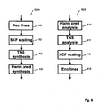
- the "Spec dec” and “Spec enc” blocks 403, 404 of Fig. 4 are described in more detail.
- the "Spec enc” block 603 illustrated to the right in the figure comprises in an embodiment an Harmonic Prediction analysis module 610, a TNS analysis (Temporal Noise Shaping) module 611, followed by a scale-factor scaling module 612 of the MDCT lines, and finally quantization and encoding of the lines in a Enc lines module 613.
- the decoder "Spec Dec” block 604 illustrated to the left in the figure does the inverse process, i.e. the received MDCT lines are de-quantized in a Dec lines module 620 and the scaling is un-done by a scalefactor (SCF) scaling module 621.
- SCF scalefactor
- Fig. 7 another preferred embodiment of the present invention is outlined.
- a QMF analysis module 710 and a QMF synthesis module 711 are added, along with a SBR (Spectral Band Replication) module 712.
- a QMF (Quadrature Mirror Filter) filterbank has a certain number of subbands, in this particular example 64.
- a complex QMF filterbank allows independent manipulation of the subbands and without introducing frequency domain aliasing above the aliasing rejection level given the prototype filter used.
- a certain number of the lower (in frequency) subbands are then synthesized to the time-domain, thus creating a downsampled signal, here by a factor of two.
- This is the input signal to the encoder modules as previously described.
- the higher 32 subbands are sent to the SBR encoder module 712 that extracts relevant SBR parameters from the highband original signal.
- the input signal is supplied to a QMF analysis module, which in turn is connected to the SBR encoder, and a downsampling module which produces a downsampled signal for the transform encoder modules as previously described.
- SBR Spectrum Band Replication
- a perceptual audio coder may reduce bit rate by shaping the quantization noise so that it is always masked by the signal. This leads to a rather low signal to noise ratio, but as long as the quantization noise is put below the masking curve this does not matter.
- the distortion that the quantization represents is inaudible. However, when operated at low bit rates, the masking threshold will be violated, and the distortion becomes audible.
- One method that a perceptual audio coder can employ is to low pass filter the signal, i.e. only coding parts of the spectrum, since there is simply not enough bits to code the entire frequency range of the signal. For this situation, the SBR algorithm is very beneficial since it enables full audio bandwidth at low bit rates.
- the SBR decoding concept comprises the following aspects:
- Fig. 8 an embodiment of the invention is extended to stereo, by adding two QMF analysis filterbanks 820, 821 for the left and right channels, and a rotation module 830, called parametric stereo (PS) module, that recreates two new signals from the two input signals in the QMF domain and corresponding rotation parameters.
- the two new signals represent a mono downmix and a residual signal. They can be visualizes as a Mid/Side transformation of the Left/Right stereo signals, where the Mid/Side stereo space is rotated so that the energy in the Mid signal (i.e. the downmix signal) is maximized, and the energy in the Side signal (i.e. the residual signal) is minimized.
- a mono source panned 45 degree to either the left or the right will be present (at different levels) in both the left channel and the right channel.
- a prior art waveform audio coder typically chooses between coding the left and right channel independently or as a Mid/Side representation.
- neither the Left/Right representation nor the Mid/Side representation will be beneficial, since the panned mono source will be present in both channels disregarded the representation.
- the Mid/Side representation is rotated 45 degrees, the panned mono source will end up entirely in the rotated Mid channel (here called the downmix channel), and the rotated Side channel will be zero (here called the residual channel). This offers a coding advantage over normal Left/Right or Mid/Side coding.
- the two new signals representing the stereo signal in combination with the extracted parameters, may subsequently be input, e.g., to the QMF synthesis modules and SBR modules as outlined in Fig. 7 .
- the residual signal can be low pass filtered or completely omitted.
- the parametric stereo decoder will replace the omitted residual signal by a decorrelated version of the downmix signal.
- this proposed processing of stereo signals can be combined with other embodiments of the present invention, too.
- the PS module compares the two input signals (left and right) for corresponding time/frequency tiles.
- the frequency bands of the tiles are designed to approximate a psycho-acoustically motivated scale, while the length of the segments is closely matched to known limitations of the binaural hearing system.
- three parameters are extracted per time/frequency tile, representing the perceptually most important spatial properties:
- the input signals are downmixed to form a mono signal.
- the downmix can be made by trivial means of a summing process, but preferably more advanced methods incorporating time alignment and energy preservation techniques are incorporated to avoid potential phase cancellation in the downmix.
- a PS decoding module is provided that basically comprises the reverse process of the corresponding encoder and reconstructs stereo output signals based on the PS parameters.
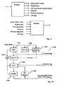
- Fig. 9 another embodiment of the present invention is outlined.
- the input signal is again analyzed by a 64 subband channel QMF module 920.
- the border between the range covered by the core coder and the SBR coder is variable.
- the system synthesizes in module 911 as many subbands needed in order to cover the bandwidth of the time-domain signal that is subsequently to be coded by the LPC, MDCT and LTP module 901.
- the remaining (higher in frequency) subband samples are input to SBR encoder 912.
- the high subband samples may also be input to a QMF synthesis module 920 that synthesizes the higher frequency range to a low-pass signal, thus containing a downmodulated high frequency range.
- This signal is subsequently coded by an additional MDCT-based MDCT-based coder 930.
- the output from the additional MDCT-based MDCT-based coder 930 may be combined with the SBR encoder output in an optional combination unit 940. Signaling is generated and sent to the decoder indicating which part is coded with SBR, and which part is coded with the MDCT-based wave-form coder. This enables a smooth transition from SBR encoding to wave-form coding. Further, freedom of choice with regards to transform sizes used in the MDCT coding for the lower frequencies and the higher frequencies is enabled, since they are coded with separate MDCT transforms.
- Fig.10 another embodiment is outlined.
- the input signal is input to an QMF analysis module 1010.
- the output subbands corresponding to the SBR range are input to SBR encoder 1012.
- LPC analysis and filtering is done by covering the entire frequency range of the signal, and is done using either directly the input signal, or a synthesized version of the QMF subband signal generated by the QMF synthesis module 1011. The latter is useful when combined with the stereo implementation of Fig 8 .
- the LPC filtered signal is input to MDCT analysis module 1002 providing spectral lines to be coded.
- quantization 1003 is arranged so that a significantly coarser quantization takes place in the SBR region (i.e.
- This information is input to a combination unit 1040 that, given the quantized spectrum and the SBR encoded data, provides signaling to the decoder what signal to use for different frequency ranges in the SBR range, i.e. either SBR data or wave-form coded data.
- Fig.11 a very general illustration of the inventive coding system is outlined.
- the exemplary encoder takes the input signal and produces a bitstream containing, among other data:
- the decoder reads the provided bitstream and produces an audio output signal, psycho-acoustically resembling the original signal.
- Fig. 11a is another illustration of aspects of an encoder 1100 according to an embodiment of the invention.
- the encoder 1100 comprises an LPC module 1101, a MDCT module 1104, a LTP module 1105 (shown only simplified), a quantization module 1103 and an inverse quantization module 1104 for feeding back reconstructed signals to the LTP module 1105.
- a pitch estimation module 1150 for estimating the pitch of the input signal
- a window sequence determination module 1151 for determining the optimal MDCT window sequence for a larger block of the input signal (e.g. 1 second).
- the MDCT window sequence is determined based on an open-loop approach where sequence of MDCT window size candidates is determined that minimizes a coding cost function, e.g.
- the contribution of the LTP module 1105 to the coding cost function that is minimized by the window sequence determination module 1151 may optionally be considered when searching for the optimal MDCT window sequence.
- the best long term prediction contribution to the MDCT frame corresponding to the window size candidate is determined, and the respective coding cost is estimated.
- short MDCT frame sizes are more appropriate for speech input while long transform windows having a fine spectral resolution are preferred for audio signals.
- Perceptual weights or a perceptual weighting function are determined based on the LPC parameters as calculated by the LPC module 1101, which will be explained in more detail below.
- the perceptual weights are supplied to the LTP module 1105 and the quantization module 1103, both operating in the MDCT-domain, for weighting error or distortion contributions of frequency components according to their respective perceptual importance.
- Fig. 11a further illustrates which coding parameters are transmitted to the decoder, preferably by an appropriate coding scheme as will be discussed later.
- the LP module filters the input signal so that the spectral shape of the signal is removed, and the subsequent output of the LP module is a spectrally flat signal.
- This is advantageous for the operation of, e.g., the LTP.
- other parts of the codec operating on the spectrally flat signal may benefit from knowing what the spectral shape of the original signal was prior to LP filtering. Since the encoder modules, after the filtering, operate on the MDCT transform of the spectrally flat signal, the present invention teaches that the spectral shape of the original signal prior to LP filtering can, if needed, be re-imposed on the MDCT representation of the spectrally flat signal by mapping the transfer function of the used LP filter (i.e.
- the LP module can omit the actual filtering, and only estimate a transfer function that is subsequently mapped to a gain curve which can be imposed on the MDCT representation of the signal, thus removing the need for time domain filtering of the input signal.
- an MDCT-based transform coder is operated using a flexible window segmentation, on a LPC whitened signal.
- a LPC whitened signal
- the LPC operates on a constant frame-size (e.g. 20 ms), while the MDCT operates on a variable window sequence (e.g. 4 to 128 ms). This allows for choosing the optimal window length for the LPC and the optimal window sequence for the MDCT independently.
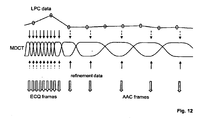
- Fig. 12 further illustrates the relation between LPC data, in particular the LPC parameters, generated at a first frame rate and MDCT data, in particular the MDCT lines, generated at a second variable rate.
- the downward arrows in the figure symbolize LPC data that is interpolated between the LPC frames (circles) so as to match corresponding MDCT frames. For instance, a LPC-generated perceptual weighting function is interpolated for time instances as determined by the MDCT window sequence.
- the upward arrows symbolize refinement data (i.e. control data) used for the MDCT lines coding. For the AAC frames this data is typically scalefactors, and for the ECQ frames the data is typically variance correction data etc.
- the solid vs dashed lines represent which data is the most "important" data for the MDCT lines coding given a certain quantizer.
- the double downward arrows symbolize the coded spectral lines.
- LPC and MDCT data in the encoder may be exploited, for instance, to reduce the bit requirements of encoding MDCT scalefactors by taking into account a perceptual masking curve estimated from the LPC parameters.
- LPC derived perceptual weighting may be used when determining quantization distortion.
- the quantizer operates in two modes and generates two types of frames (ECQ frames and AAC frames) depending on the frame size of received data, i.e. corresponding to the MDCT frame or window size.
- Fig. 15 illustrates a preferred embodiment of mapping the constant rate LPC parameters to adaptive MDCT window sequence data.
- a LPC mapping module 1500 receives the LPC parameters according to the LPC update rate.
- the LPC mapping module 1500 receives information on the MDCT window sequence. It then generates a LPC-to-MDCT mapping, e.g., for mapping LPC-based psycho-acoustic data to respective MDCT frames generated at the variable MDCT frame rate.
- the LPC mapping module interpolates LPC polynomials or related data for time instances corresponding to MDCT frames for usage, e.g., as perceptual weights in LTP module or quantizer.
- the LPC module 1301 is in an embodiment of the present invention adapted to produce a white output signal, by using linear prediction of, e.g., order 16 for a 16 kHz sampling rate signal.
- the output from the LPC module 201 in Fig. 2 is the residual after LPC parameter estimation and filtering.
- the estimated LPC polynomial A(z) as schematically visualized in the lower left of Fig. 13 , may be chirped by a bandwidth expansion factor, and also tilted by, in one implementation of the invention, modifying the first reflection coefficient of the corresponding LPC polynomial.
- the MDCT coding operating on the LPC residual has, in one implementation of the invention, scalefactors to control the resolution of the quantizer or the quantization step sizes (and, thus, the noise introduced by quantization).
- scalefactors are estimated by a scalefactor estimation module 1360 on the original input signal.
- the scalefactors are derived from a perceptual masking threshold curve estimated from the original signal.
- a separate frequency transform (having possibly a different frequency resolution) may be used to determine the masking threshold curve, but this is not always necessary.
- the masking threshold curve is estimated from the MDCT lines generated by the transformation module.
- the bottom right part of Fg. 13 schematically illustrates scalefactors generated by the scalefactor estimation module 1360 to control quantization so that the introduced quantization noise is limited to inaudible distortions.
- a whitened signal is transformed to the MDCT-domain.
- this signal has a white spectrum, it is not well suited to derive a perceptual masking curve from it.
- a MDCT-domain equalization gain curve generated to compensate the whitening of the spectrum may be used when estimating the masking threshold curve and/or the scalefactors. This is because the scalefactors need to be estimated on a signal that has absolute spectrum properties of the original signal, in order to correctly estimate perceptually masking.
- the calculation of the MDCT-domain equalization gain curve from the LPC polynomial is discussed in more detail with reference to Fig. 14 below.
- the data transmitted between the encoder and decoder contains both the LP polynomial from which the relevant perceptual information as well as a signal model can be derived when a model-based quantizer is used, and the scalefactors commonly used in a transform codec.
- the LPC module 1301 in the figure estimates from the input signal a spectral envelope A(z) of the signal and derives from this a perceptual representation A'(z).
- scalefactors as normally used in transform based perceptual audio codecs are estimated on the input signal, or they may be estimated on the white signal produced by a LP filter, if the transfer function of the LP filter is taken into account in the scalefactor estimation (as described in the context of Fig.14 below).
- the scalefactors may then be adapted in scalefactor adaptation module 1361 given the LP polynomial, as will be outlined below, in order to reduce the bit rate required to transmit scalefactors.
- the scalefactors are transmitted to the decoder, and so is the LP polynomial.
- the LP polynomial is the LP polynomial.
- this correlation is exploited as follows. Since the LPC polynomial, when correctly chirped and tilted, strives to represent a masking threshold curve, the two representations may be combined so that the transmitted scalefactors of the transform coder represent the difference between the desired scalefactors and those that can be derived from the transmitted LPC polynomial.
- the scalefactor adaptation module 1361 shown in Fig.13 therefore calculates the difference between the desired scalefactors generated from the original input signal and the LPC-derived scalefactors.
- This aspect retains the ability to have a MDCT-based quantizer that has the notion of scalefactors as commonly used in transform coders, within an LPC structure, operating on a LPC residual, and still have the possibility to switch to a model-based quantizer that derives quantization step sizes solely from the linear prediction data.
- Fig. 14 illustrates a preferred embodiment of translating LPC polynomials into a MDCT gain curve.
- the MDCT operates on a whitened signal, whitened by the LPC filter 1401.
- a MDCT gain curve is calculated by the MDCT gain curve module 1470.
- the MDCT-domain equalization gain curve may be obtained by estimating the magnitude response of the spectral envelope described by the LPC filter, for the frequencies represented by the bins in the MDCT transform.
- the gain curve may then be applied on the MDCT data, e.g., when calculating the minimum mean square error signal as outlined in Fig 3 , or when estimating a perceptual masking curve for scalefactor determination as outlined with reference to Fig. 13 above.
- Fig. 16 illustrates a preferred embodiment of adapting the perceptual weighting filter calculation based on transform size and/or type of quantizer.
- the LP polynomial A(z) is estimated by the LPC module 1601 in Fig 16 .
- a LPC parameter modification module 1671 receives LPC parameters, such as the LPC polynomial A(z), and generates a perceptual weighting filter A'(z) by modifying the LPC parameters. For instance, the bandwidth of the LPC polynomial A(z) is expanded and/or the polynomial is tilted.
- the input parameters to the adapt chirp & tilt module 1672 are the default chirp and tilt values ⁇ and ⁇ .
- the modified chirp and tilt parameters ⁇ ' and ⁇ ' are input to the LPC parameter modification module 1671 translating the input signal spectral envelope, represented by A(z), to a perceptual masking curve represented by A'(z).
- the quantization strategy conditioned on frame-size, and the model-based quantization conditioned on assorted parameters according to an embodiment of the invention will be explained.
- One aspect of the present invention is that it utilizes different quantization strategies for different transform sizes or frame sizes. This is illustrated in Fig. 17 , where the frame size is used as a selection parameter for using a model-based quantizer or a non-model based quantizer. It must be noted that this quantization aspect is independent of other aspects of the disclosed encoder/decoder and may be applied in other codecs as well.
- An example of a non-model based quantizer is Huffman table based quantizer used in the AAC audio coding standard.
- the model-based quantizer may be an Entropy Constraint Quantizer (ECQ) employing arithmetic coding.
- ECQ Entropy Constraint Quantizer
- other quantizers may be used in embodiments of the present invention as well.
- the quantizer of choice is implicitly signaled to the decoder by means of transform size. It should be clear that other means of signaling could be used as well, e.g. explicitly sending information to the decoder on which quantization strategy has been used for a particular frame-size.
- the window-sequence may dictate the usage of a long transform for a very stationary tonal music segment of the signal.
- a quantization strategy that can take advantage of "sparse" character (i.e. well defined discrete tones) in the signal spectrum.
- a quantization method as used in AAC in combination with Huffman tables and grouping of spectral lines, also as used in AAC, is very beneficial.
- the window-sequence may, given the coding gain of the LTP, dictate the usage of short transforms.
- this signal type and transform size it is beneficial to employ a quantization strategy that does not try to find or introduce sparseness in the spectrum, but instead maintains a broadband energy that, given the LTP, will retain the pulse like character of the original input signal.
- FIG.18 A more general visualization of this concept is given in Fig.18 , where the input signal is transformed into the MDCT-domain, and subsequently quantized by a quantizer controlled by the transform size or frame size used for the MDCT transform.
- the quantizer step size is adapted as function of LPC and/ or LTP data. This allows a determination of the step size depending on the difficulty of a frame and controls the number of bits that are allocated for encoding the frame.
- Fig. 19 an illustration is given on how model-based quantization may be controlled by LPC and LTP data.
- a schematic visualization of MDCT lines is given. Below the quantization step size delta A as a function of frequency is depicted. It is clear from this particular example that the quantization step size increases with frequency, i.e. more quantization distortion is incurred for higher frequencies.
- the delta-curve is derived from the LPC and LTP parameters by means of a delta-adapt module depicted in Fig. 19a .
- the delta curve may further be derived from the prediction polynomial A(z) by chirping and/or tilting as explained with reference to Fig. 13 .
- A(z) is the LPC polynomial
- ⁇ is a tilting parameter
- ⁇ controls the chirping
- r i is the first reflection coefficient calculated from the A(z) polynomial.
- the A(z) polynomial can be re-calculate to an assortment of different representations in order to extract relevant information from the polynomial. If one is interested in the spectral slope in order to apply a "tilt" to counter the slope of the spectrum, re-calculation of the polynomial to reflection coefficients is preferred, since the first reflection coefficient represents the slope of the spectrum.
- the delta values ⁇ may be adapted as a function of the input signal variance ⁇ , the LTP gain g, and the first reflection coefficient r i derived from the prediction polynomial.
- Fig. 20 one of the aspects of the model-based quantizer is visualized.
- the MDCT lines are input to a quantizer employing uniform scalar quantizers.
- random offsets are input to the quantizer, and used as offset values for the quantization intervals shifting the interval borders.
- the proposed quantizer provides vector quantization advantages while maintaining searchability of scalar quantizers.
- the quantizer iterates over a set of different offset values, and calculates the quantization error for these.
- the offset value (or offset value vector) that minimizes the quantization distortion for the particular MDCT lines being quantized is used for quantization.
- the offset value is then transmitted to the decoder along with the quantized MDCT lines.
- the use of random offsets introduces noise-filling in the de-quantized decoded signal and, by doing so, avoids spectral holes in the quantized spectrum. This is particularly important for low bit rates where many MDCT lines are otherwise quantized to a zero value which would lead to audible holes in the spectrum of the reconstructed signal.
- Fig. 21 illustrates schematically a Model based MDCT Lines Quantizer (MBMLQ) according to an embodiment of the invention.
- the top of Fig 21 depicts a MBMLQ encoder 2100.
- the MBMLQ encoder 2100 takes as input the MDCT lines in an MDCT frame or the MDCT lines of the LTP residual if an LTP is present in the system.
- the MBMLQ employs statistical models of the MDCT lines, and source codes are adapted to signal properties on an MDCT frame-by-frame basis yielding efficient compression to a bitstream.
- a local gain of the MDCT lines may be estimated as the RMS value of the MDCT lines, and the MDCT lines normalized in gain normalization module 2120 before input to the MHMLQ encoder 2100.
- the local gain normalizes the MDCT lines and is a complement to the LP gain normalization. Whereas the LP gain adapts to variations in signal level on a larger time scale, the local gain adapts to variations on a smaller time scale, yielding improved quality of transient sounds and on-sets in speech.
- the local gain is encoded by fixed rate or variable rate coding and transmitted to the decoder.
- a rate control module 2110 may be employed to control the number of bits used to encode an MDCT frame.
- a rate control index controls the number of bits used.
- the rate control index points into a list of nominal quantizer step sizes. The table may be sorted with step sizes in descending order.
- the MBMLQ encoder is run with a set of different rate control indices, and the rate control index that yields a bit count which is lower than the number of granted bits given by the bit reservoir control is used for the flame.
- the rate control index varies slowly and this can be exploited to reduce search complexity and to encode the index efficiently.
- the set of indices that is tested can be reduced if testing is started around the index of the previous MDCT frame.
- efficient entropy coding of the index is obtained if the probabilities peak around the previous value of the index.
- the rate control index can be coded using 2 bits per MDCT frame on the average.
- Fig. 21 further illustrates schematically the MBMLQ decoder 2150 where the MDCT frame is gain renormalized if a local gain was estimated in the encoder 2100.
- Fig. 21a illustrates schematically the model-based entropy constrained encoder 2140 in more detail.
- the aim of the subsequent coding is to introduce white quantization noise to the MDCT lines in the perceptual domain.
- the inverse of the perceptual weighting is applied which results in quantization noise that follows the perceptual masking curve.
- Random offsets were discussed previously in the context of the quantizer as means for avoiding spectral holes due to coarse quantization.
- An additional method for avoiding spectral holes is to incorporate an SBR module 2212 in the LTP loop, as outlined in Fig. 22 .
- the SBR module 2212 is operating in the MDCT domain, and re-generates high frequencies from lower frequencies.
- the SBR module in the LTP loop does not need any envelope adjustment, since the entire operation is performed in the spectrally flat MDCT domain.
- the advantage of putting the high frequency reconstruction module in the LTP loop is that the high frequency regenerated signal is subtracted prior to quantization and added after quantization.
- the quantizer will encode the signal so that the original high frequencies are retained (since the SBR contribution is subtracted prior to quantization and added after quantization), and if the bit constraints are too sever, the quantizer will not be able to produce energy in the high frequencies, and the SBR regenerated high frequencies is added at the output as a "fall back" thus ensuring energy in the high frequency range.
- the SBR module in the LTP loop is a simple copy-up (i.e. low frequency lines are copied to high frequency lines) mechanism.
- a harmonic high frequency regeneration module is used. It should be noted that for harmonic signal, a SBR module that creates a high frequency spectrum that is harmonically related to the low band spectrum is preferred since the high frequencies subtracted from the input signal prior to quantization may coincide well with the original high frequencies and thus reduce the energy of the signal going into the quantizer, thus making it easier to quantize given a certain bit rate requirement.
- the SBR module in the LTP loop can adapt the manner in which it re-creates the high frequencies depending on the transform size and thus, implicitly, the signal characteristics.
- the present invention further incorporates a new window sequence coding format.
- the windows used for the MDCT transformation are of dyadic sizes, and may only vary a factor two in size from window to window.
- Dyadic transform sizes are, e.g., 64, 128, ..., 2048 samples corresponding to 4, 8, ..., 128 ms at 16 kHz sampling rate.
- variable size windows are proposed which can take on a plurality of window sizes between a minimum window size and a maximum size. In a sequence, consecutive window sizes may vary only by a factor of two so that smooth sequences of window sizes without abrupt changes develop.
- the window sequences as defined by an embodiment i.e. limited to dyadic sizes and only allowed to vary a factor two in size from window to window, have several advantages. Firstly, no specific start or stop windows are needed, i.e. windows with sharp edges. This maintains a good time/frequency resolution. Secondly, the window sequence becomes very efficient to code, i.e. to signal to a decoder what particular window sequence is used. According to an embodiment, only one bit is necessary to signal whether the next window in the sequence increases by the factor two or decreases by two. Of course, other coding schemas are possible which efficiently code an entire sequence of window sizes given the above constrains. Finally, the window sequence will always fit nicely into a hyperframe structure.
- the hyper-frame structure is useful when operating the coder in a real-world system, where certain decoder configuration parameters need to be transmitted in order to be able to start the decoder.
- This data is commonly stored in a header field in the bitstream describing the coded audio signal.
- the header is not transmitted for every frame of coded data, particularly in a system as proposed by the present invention, where the MDCT frame-sizes may vary from very short to very large. It is therefore proposed by the present invention to group a certain amount of MDCT frames together into a hyper frame, where the header data is transmitted at the beginning of the hyper frame.
- the hyper frame is typically defined as a specific length in time. Therefore, care needs to be taken so that the variations of MDCT frame-sizes fits into a constant length, pre-defined hyper frame length.
- the above outlined inventive window-sequence ensures that the selected window sequence always fits into a hyper-frame structure.
- Fig. 23a shows a preferred compatibility requirement for adjacent windows of an MDCT transform, as given by MDCT theory.
- the left window accommodates a transform size L 1 and the right window a transform size L 2 .
- the overlap between the windows is supported on a time interval of diameter, or duration, D.
- the figure depicts the latter situation.
- the position of the transform size intervals must be obtained by a dyadic partition of a regular equidistant hyperframe sequence.
- the transform interval positions must result from a succession of splitting intervals in halves, starting from a hyperframe interval. Even when the transform size intervals are given, there is some freedom left in choosing the overlap diameter D. According to an embodiment of the present invention, diameters D very much smaller than the neighboring transform sizes L 1 , L 2 are avoided, since such sharp edges lead to poor frequency resolution of the resulting MDCT transforms.
- Fig. 23b schematically illustrates an embodiment of the present invention using four different MDCT window shapes.
- the four shapes are denoted by LL: long left and long right overlap; LS: long left and short right overlap; SL: short left and long right overlap; SS: short left and short right overlap.
- the MDCT windows used are re-scaled versions of these four window types, where the rescaling is by a factor equal to a power of two.
- the tick marks on the time axis in Fig. 23b denote the transform size intervals, and as it can be seen, the diameter of a long overlap is equal to the transform sizes, whereas the diameter of a short overlap is half the size.
- there is a largest transform size which is 2 N times the smallest transform size, with N typically equal to an integer less than 6.
- the LL window may be considered.
- Fig. 23c describes by an example the window sequence encoding method according to an embodiment of the present invention.
- the scale of the time axis is normalized to units of the smallest transform size.
- the transform size intervals form a dyadic portion of the hyperframe interval [0,16], consisting of the 7 intervals [0,4], [4,6], [6,8], [8,9], [9,10], [10,12], [12,16] having lengths 4, 2, 2, 1, 1, 2, 4, respectively. As can be seen, these lengths obey the condition of at most changing size by a factor of two between neighbors. All 7 windows are obtained by rescaling of one of the four basic shapes of Fig. 23b .
- the left most overlap size of 4 units is an initial state of the current hyperframe obtained by either the final state of the previous hyperframe or by absolute transmission in the case of an independent hyperframe.
- the transform size bit b 1 for the third window has value 0, but here the option of a longer transform is not consistent with dyadic structure so the bit can be deduced from the situation, hence it is not transmitted and crossed out in the figure.
- the three bits above [9,10] are crossed out on the grounds of no use of overlap for shortest transform size, and wrong position for zoom up.
- the full uncrossed bit sequence is 01000100001011 but after using information available at both encoder and decoder it is reduced to 100101011 which is 9 bits for coding 7 windows.
- Fig. 24 an additional feature of the inventive encoder/decoder system is presented.
- the input signal is input to the MDCT analysis module, and the MDCT representation of the signal is input into a harmonic prediction module 2400.
- Harmonic prediction is a filtering along the frequency) axis, given a parametric filter. Given pitch information, gain information and phase information, the higher (in frequency) MDCT lines can then be predicted from the lower lines, if the input signal contains a harmonic series.
- Control parameters for the harmonic prediction module are pitch information, gain and phase information.
- virtual LTP vectors in the MDCT-domain are used, as outlined in Fig. 25 which depicts the two modules involved: LTP extraction module 2512 and LTP refinement module 2518.
- LTP is that a previous segment of the output signal is used for the decoding of the present segment or frame. Which previous segment to use is decided by the LTP extraction module 2512 given an iterative process minimizing the distortion of the coded signal.
- the present invention provides a new method of taking into account the overlap of the MDCT frames, i.e. when the LTP lag is chosen so that the segment of the previous output signal that will be MDCT analyzed and used in the decoding process of the current output segment includes, due to the overlap, parts of the present output segment that has not been produced yet.
- This iterative process is illustrated in the following: From the LTP buffer, a first extraction of a signal is performed by the LTP extraction module 2512. The result of this first extraction is refined by the refinement module 2518, the purpose of which it is to improve the quality of the LTP signal when the chosen lag T is smaller than the duration of the MDCT window of the frame to be coded.
- the iterative process to refine an LTP contribution for a time lag that is smaller than the analyzed frame is briefly outlined first by referring to Fig. 25a .
- the chosen segment in the LTP buffer is displayed, with the MDCT analysis window superimposed.
- the right part of the overlap window does not contain available data: the dashed line part of the time-signal.
- the iterative refinement process goes through the following steps:
- This iterative process is preferably done 2 to 4 times.
- Fig. 25b which shows the steps performed by the LTP extraction module:
- the windowing then consists of a simple extraction of the signal x 1 (t) in the interval [t 1 , t 2 ].
- the LTP extraction module 2512 performs exactly what a prior art LTP extractor would do.
- Fig. 25c illustrates the iterative refinement of an initial LTP extracted signal y 2 (t). It consists of applying the LTP extract operation N-1 times, and adding the results to the initial signal.
- S denotes the LTP extract operation
- the LTP lag and the LTP gain are coded in a variable rate fashion. This is advantageous since, due to the LTP effectiveness for stationary periodic signals, the LTP lag tends to be the same over somewhat long segments. Hence, this can be exploited by means of arithmetic coding, resulting in a variable rate LTP lag and LTP gain coding.
- an embodiment of the present invention takes advantage of a bit reservoir and variable rate coding also for the coding of the LP parameters.
- recursive LP coding is taught by the present invention.
- Fig. 26 schematically shows a combination unit 2600 for combining pitch and pitch related parameters such as LTP lag and delta pitch from time-warping, and that produces a combined pitch signaling.
- the codec may utilize a LTP in the MDCT-domain.
- two additional LTP buffers 2512, 2513 may be introduced.
- a noise vector and a pulse-vector are also included in the search.
- Noise and pulses may be used as prediction signals, e.g. in transients when the signal of previous segments as stored in the LTP buffer is not suitable.
- an enhanced LTP with pulse and noise codebook entries is presented.
- bit reservoir control unit is taught.
- the bit reservoir control unit receives information on the frame length of the current frame.
- An example of a difficulty measure for usage in the bit reservoir control unit is perceptual entropy, or the logarithm of the power spectrum.
- Bit reservoir control is important in a system where the frame lengths can vary over a set of different frame lengths.
- the suggested bit reservoir control unit takes the frame length into account when calculating the number of granted bits for the frame to be coded as will be outlined below.
- the bit reservoir is defined here as a certain fixed amount of bits in a buffer that has to be larger than the average number of bits a frame is allowed to use for a given bit rate. If it is of the same size, no variation in the number of bits for a frame would be possible.
- the bit reservoir control always looks at the level of the bit reservoir before taking out bits that will be granted to the encoding algorithm as allowed number of bits for the actual frame. Thus a full bit reservoir means that the number of bits available in the bit reservoir equals the bit reservoir size. After encoding of the frame, the number of used bits will be subtracted from the buffer and the bit reservoir gets updated by adding the number of bits that represent the constant bit rate. Therefore the bit reservoir is empty, if the number of the bits in the bit reservoir before coding a frame is equal to the number of average bits per frame.
- Fig. 28a the basic concept of bit reservoir control is depicted.
- the encoder provides means to calculate how difficult to encode the actual frame compared to the previous frame is.
- For an average difficulty of 1.0 the number of granted bits depends on the number of bits available in the bit reservoir. According to a given line of control, more bits than corresponding to an average bit rate will be taken out of the bit reservoir if the bit reservoir is quite full. In case of an empty bit reservoir, less bits compared to the average bits will be used for encoding the frame. This behavior yields to an average bit reservoir level for a longer sequence of frames with average difficulty. For frames with a higher difficulty, the line of control may be shifted upwards, having the effect that difficult to encode frames are allowed to use more bits at the same bit reservoir level.
- the number of bits allowed for a frame will be lower just by shifting down the line of control in Fig. 28a from the average difficulty case to the easy difficulty case.
- Other modifications than simple shifting of the control line are possible, too.
- the slope of the control curve may be changed depending on the frame difficulty.
- bit reservoir control scheme including the calculation of the granted bits by a control line as shown in Fig. 28a is only one example of possible bit reservoir level and difficulty measure to granted bits relations. Also other control algorithms will have in common the hard limits at the lower end of the bit reservoir level that prevent a bit reservoir to violate the empty bit reservoir restriction, as well as the limits at the upper end, where the encoder will be forced to write fill bits, if a too low number of bits will be consumed by the encoder.
- this simple control algorithm has to be adapted.
- the difficulty measure to be used has to be normalized so that the difficulty values of different frame sizes are comparable.
- For every frame size there will be a different allowed range for the granted bits, and because the average number of bits per frame is different for a variable frame size, consequently each frame size has its own control equation with its own limitations.
- One example is shown in Fig. 28b .
- An important modification to the fixed frame size case is the lower allowed border of the control algorithm. Instead of the average number of bits for the actual frame size, which corresponds to the fixed bit rate case, now the average number of bits for the largest allowed frame size is the lowest allowed value for the bit reservoir level before taking out the bits for the actual frame. This is one of the main differences to the bit reservoir control for fixed frame sizes. This restriction guarantees that a following frame with the largest possible frame size can utilize at least the average number of bits for this frame size.
- the difficulty measure may be based, e.g., a perceptual entropy (PE) calculation that is derived from masking thresholds of a psychoacoustic model as it is done in AAC, or as an alternative the bit count of a quantization with fixed step size as it is done in the ECQ part of an encoder according to an embodiment of the present invention.
- PE perceptual entropy
- These values may be normalized with respect to the variable frame sizes, which may be accomplished by a simple division by the frame length, and the result will be a PE respectively a bit count per sample.
- Another normalization step may take place with regard to the average difficulty. For that purpose, a moving average over the past frames can be used, resulting in a difficulty value greater than 1.0 for difficult frames or less than 1.0 for easy frames. In case of a two pass encoder or of a large lookahead, also difficulty values of future frames could be taken into account for this normalization of the difficulty measure.
- Fig. 29 outlines a warped MDCT-domain as used in an embodiment of the proposed encoder and decoder.
- time-warping means resampling the time scale to achieve constant pitch.
- the x-axis of the figure shows the input signal with varying pitch, and the y-axis of the figure shows the resampled constant pitch signal.
- the time warping curve may be determined by using a pitch detection algorithm on the present segment, and estimating the pitch evolvement in the segment.
- the pitch evolvement information is then used to resample the signal in the segment, thus generating the warping curve.
- the algorithm to establish the warping curve is robust against pitch detection errors.
- the time-warped MDCT is used in combination with LTP.
- the LTP search is done in a constant pitch segment domain in the encoder. This is particular useful for long MDCT frames comprising several pitch pulses which - due to the pitch variation - are not arranged equidistant in the MDCT frame. Thus, a constant pitch segment from the LTP buffer will not fit properly over the plurality of pitch pulses.
- all segments in the LTP buffer are resampled based on the warping curve of the present MDCT frame.
- the selected segment in the LTP buffer is resampled to the warp data of the present frame, given the warp data information.
- the warp information may be is transmitted to the decoder as part of the bitstream.
- Fig. 29 windows, i.e. segments in the LTP buffer, are indicated, along with the window of the present, dashed, frame.
- Fig. 29a the effects of the warped MDCT analysis are visible.
- To the left is presented the frequency plot of un-warped analysis. Due to a pitch change over the window, the harmonics higher up in frequency do not get properly resolved.
- In the right part of the figure is the frequency plot of the same signal, albeit analyzed with a time-warped MDCT analysis. Since the pitch is now constant over the analysis window, the higher harmonics are better resolved.
- the encoder and decoder can be implemented as a dual rate system where the core coder is sampled at half of the sampling rate, and a high frequency reconstruction module takes care of the higher frequencies, sampled at the original sampling rate. Assuming an original sampling rate of 32 kHz, the LPC filter operates on 16 kHz sampling frequency, providing 8 kHz of whitened signal. The following core coder may however not be able to code 8 kHz of bandwidth given the bit rate constraints imposed. The present invention provides several means to handle this. An embodiment of the invention applies a high frequency reconstruction in the MDCT-domain under the LPC (i.e.
- the LPC covers the frequency range from zero to 8 kHz, and the range from 0 to 5 kHz is handled by the MDCT wave-form quantizer.
- the frequency range from 5 to 8 kHz is handled by an MDCT SBR algorithm, and finally the range from 8 to 16 kHz is handled by a QMF SBR algorithm.
- the MDCT SBR is based on a similar copy-up mechanism as is used in the QMF based SBR as described above. However, other methods may also advantageously be used, such as adapting the MDCT SBR method as a function of transform size.
- the upper frequency range of the LP spectrum is quantized and coded dependent on frame size and signal properties.
- the frequency range is coded according to the above, and for other transform sizes sparse quantization and noise-fill techniques are employed.
Landscapes
- Engineering & Computer Science (AREA)
- Physics & Mathematics (AREA)
- Spectroscopy & Molecular Physics (AREA)
- Multimedia (AREA)
- Audiology, Speech & Language Pathology (AREA)
- Human Computer Interaction (AREA)
- Health & Medical Sciences (AREA)
- Acoustics & Sound (AREA)
- Signal Processing (AREA)
- Computational Linguistics (AREA)
- Mathematical Physics (AREA)
- Compression, Expansion, Code Conversion, And Decoders (AREA)
- Reduction Or Emphasis Of Bandwidth Of Signals (AREA)
- Stereo-Broadcasting Methods (AREA)
- Analogue/Digital Conversion (AREA)
- Compression Or Coding Systems Of Tv Signals (AREA)
Claims (19)
- Système de codage audio, comprenant :une unité de prédiction linéaire (201, 401), destinée à filtrer un signal d'entrée, sur la base d'un filtre adaptatif ;une unité de transformation (202, 302, 402), destinée à transformer une trame du signal d'entrée filtré dans un domaine de transformation, dans lequel la transformation appliquée à la trame du signal d'entrée filtré est une transformation en cosinus discrète modifiée, MDCT pour « Modified Discrete Cosine Transform » ;une unité de quantification (203, 303, 403), destinée à quantifier un signal dans le domaine de transformation ;une unité de prédiction à long terme (205, 310, 410), destinée à déterminer une estimation de la trame du signal d'entrée filtré sur la base d'une reconstruction d'un segment précédent du signal d'entrée filtré ; etune unité de combinaison du signal dans le domaine de transformation, destinée à combiner, dans le domaine de transformation, l'estimation de prédiction à long terme et le signal d'entrée filtré transformé, pour produire le signal dans le domaine de transformation ;caractérisé en ce que l'unité de prédiction à long terme (205, 310, 410) comprend :un extracteur de prédiction à long terme (312, 412), destiné à déterminer une valeur de retard spécifiant le segment reconstruit du signal filtré qui correspond au mieux à la trame courante du signal filtré ;un estimateur de gain de prédiction à long terme (313, 413), destiné à estimer une valeur de gain appliquée au signal du segment sélectionné du signal filtré, dans lequel la valeur de retard et la valeur de gain sont déterminées de manière à minimiser un critère de distorsion ; etun générateur de vecteur virtuel, destiné à produire un segment étendu du signal reconstruit lorsque la valeur de retard est inférieure à la longueur d'une trame MDCT, dans lequel le générateur de vecteur virtuel raffine le segment produit du signal reconstruit en repliant itérativement des parties du signal reconstruit dans une fenêtre MDCT correspondant à la valeur de retard et en dehors de celle-ci.
- Système de codage audio selon la revendication 1, dans lequel :le filtre adaptatif, destiné à filtrer le signal d'entrée, est basé sur une analyse par codage prédictif linéaire, LPC pour « Linear Prediction Coding », fonctionnant sur une première longueur de trame et produisant un signal d'entrée blanchi ; etla transformation appliquée à la trame du signal d'entrée filtré est une transformation en cosinus discrète modifiée fonctionnant sur une seconde longueur de trame variable.
- Système de codage audio selon la revendication 2, comprenant :une unité de commande de séquence de fenêtres, destinée à déterminer, pour un bloc du signal d'entrée, les secondes longueurs de trame afin de se superposer à des fenêtres MDCT en minimisant une fonction de coût du codage, de préférence une entropie perceptuelle simpliste, pour le bloc de signal d'entrée.
- Système de codage audio selon la revendication 3, dans lequel les longueurs des fenêtres MDCT sont des partitions dyadiques du bloc de signal d'entrée.
- Système de codage audio selon l'une quelconque des revendications 3 et 4, dans lequel l'unité de commande de la séquence de fenêtres est configurée pour examiner des estimations de prédiction à long terme produites par l'unité de prédiction à long terme pour des valeurs candidates de longueurs de fenêtre lorsqu'elle recherche la séquence des longueurs de fenêtres MDCT qui minimise la fonction de coût de codage pour le bloc de signal d'entrée.
- Système de codage audio selon l'une quelconque des revendications 2 à 5, comprenant un codeur de séquence de fenêtres destiné à coder conjointement des longueurs de fenêtres MDCT et des formes de fenêtres dans une séquence.
- Système de codage audio selon l'une quelconque des revendications précédentes, comprenant un codeur de bande supérieure, destiné à coder une composante de bande supérieure du signal d'entrée, dans lequel les étapes de quantification utilisées dans l'unité de quantification pour quantifier le signal dans le domaine de transformation sont différentes pour le codage de composantes du signal dans le domaine de transformation appartenant à la bande supérieure que pour des composantes appartenant à une bande inférieure du signal d'entrée.
- Système de codage audio selon l'une quelconque des revendications 1 à 7, comprenant :une unité de division de fréquences, destinée à diviser le signal d'entrée en une composante de bande inférieure et une composante de bande supérieure ; etun codeur de bande supérieure, destiné à coder la composante de bande supérieure ;dans lequel la composante de bande inférieure est envoyée à l'unité de prédiction linéaire.
- Système de codage audio selon la revendication 8, dans lequel la frontière entre la bande inférieure et la bande supérieure est variable et l'unité de division de fréquences détermine la fréquence de coupure sur la base des propriétés du signal d'entrée et/ou des exigences de bande passante du codeur.
- Système de codage audio selon l'une quelconque des revendications 8 et 9, comprenant une unité de combinaison de représentation du signal, destiné à combiner différentes représentations du signal couvrant la même plage de fréquences et produire des données de signalisation indiquant comment les représentations du signal sont combinées.
- Système de codage audio selon l'une quelconque des revendications précédentes, dans lequel l'unité de prédiction à long terme comprend une unité de réplication de bande spectrale, destinée à introduire de l'énergie dans les composantes à haute fréquence des estimations de prédiction à long terme.
- Système de codage audio selon l'une quelconque des revendications précédentes, comprenant une unité stéréo paramétrique, destinée à calculer une représentation stéréo paramétrique des canaux d'entrée gauche et droit.
- Système de codage audio selon l'une quelconque des revendications précédentes, dans lequel l'unité de quantification décide, sur la base des caractéristiques du signal d'entrée, de coder le signal dans le domaine de transformation à l'aide d'un quantificateur à base de modèle ou non.
- Système de codage audio selon la revendication 1, dans lequel un polynôme de prédiction linéaire modifié, produit par une unité de modélisation perceptuelle, est appliqué comme courbe de gain d'égalisation dans le domaine MDCT pour minimiser le critère de distorsion.
- Système de codage audio selon l'une quelconque des revendications 1 à 14, dans lequel l'unité de prédiction à long terme comprend une unité de transformation destinée à transformer le signal reconstruit du segment sélectionné dans le domaine de transformation, la transformation étant de préférence une transformation à cosinus discrète de type IV.
- Système de codage audio selon l'une quelconque des revendications 1 à 15, dans lequel l'unité de transformation travaille sur des signaux warpés dans le temps et dans lequel l'unité de prédiction à long terme rééchantillonne le signal d'entrée filtré reconstruit sur la base d'une courbe de warping temporel.
- Système de codage audio selon l'une quelconque des revendications précédentes, dans lequel l'unité de prédiction à long terme comprend un tampon de vecteur de bruit et/ou un tampon de vecteur d'impulsions.
- Système de codage audio selon l'une quelconque des revendications précédentes, comprenant une unité de codage conjoint destinée à coder conjointement des informations liées au niveau telles que des paramètres de prédiction à long terme, des paramètres de prédiction harmonique et des paramètres de warping temporel.
- Décodeur audio, comprenant :une unité de déquantification (211) destinée à déquantifier une trame dans un flux de bits d'entrée ;une unité de transformation inverse (212), destinée à appliquer une transformation inverse à un signal dans le domaine de transformation, dans lequel le signal dans le domaine de transformation est fondé sur une transformation à cosinus discrète modifiée ;une unité de prédiction à longterme (214), destinée à déterminer une estimation de prédiction à long terme de la trame déquantifiée, sur la base d'une valeur de retard et d'une valeur de gain reçues dans le flux de bits ;une unité de combinaison du signal dans le domaine de transformation, destinée à combiner, dans le domaine de transformation, l'estimation de prédiction à long terme et la trame déquantifiée, pour produire le signal dans le domaine de transformation ; etune unité de prédiction linéaire (213), destinée à filtrer le signal dans le domaine de transformation qui a subi la transformation inverse ;caractérisé en ce que l'unité de prédiction à long terme (214) comprend :un tampon de prédiction à long terme (515) ; etun générateur de vecteur virtuel, destiné à produire un segment étendu du signal reconstruit qui est stocké dans le tampon de prédiction à long terme (515) lorsque la valeur de retard est inférieure à la longueur d'une trame MDCT, dans lequel le générateur de vecteur virtuel raffine le segment produit du signal reconstruit en repliant itérativement des parties du signal reconstruit dans une fenêtre MDCT correspondant à la valeur de retard et en dehors de celle-ci.
Priority Applications (5)
| Application Number | Priority Date | Filing Date | Title |
|---|---|---|---|
| KR1020107017305A KR101202163B1 (ko) | 2008-01-04 | 2008-12-30 | 오디오 인코더 및 디코더 |
| US12/811,419 US8494863B2 (en) | 2008-01-04 | 2008-12-30 | Audio encoder and decoder with long term prediction |
| JP2010541031A JP5350393B2 (ja) | 2008-01-04 | 2008-12-30 | オーディオコーディングシステム、オーディオデコーダ、オーディオエンコーディング方法及びオーディオデコーディング方法 |
| PCT/EP2008/011145 WO2009086919A1 (fr) | 2008-01-04 | 2008-12-30 | Codeur et décodeur audio |
| CN2008801255814A CN101925950B (zh) | 2008-01-04 | 2008-12-30 | 音频编码器和解码器 |
Applications Claiming Priority (1)
| Application Number | Priority Date | Filing Date | Title |
|---|---|---|---|
| SE0800032 | 2008-01-04 |
Publications (2)
| Publication Number | Publication Date |
|---|---|
| EP2077551A1 EP2077551A1 (fr) | 2009-07-08 |
| EP2077551B1 true EP2077551B1 (fr) | 2011-03-02 |
Family
ID=39710955
Family Applications (6)
| Application Number | Title | Priority Date | Filing Date |
|---|---|---|---|
| EP08009531A Active EP2077551B1 (fr) | 2008-01-04 | 2008-05-24 | Encodeur audio et décodeur |
| EP08009530A Active EP2077550B8 (fr) | 2008-01-04 | 2008-05-24 | Encodeur audio et décodeur |
| EP12195829.2A Active EP2573765B1 (fr) | 2008-01-04 | 2008-12-30 | Codeur et décodeur audio |
| EP24180870.8A Pending EP4414981A3 (fr) | 2008-01-04 | 2008-12-30 | Codeur et décodeur audio |
| EP08870326.9A Active EP2235719B1 (fr) | 2008-01-04 | 2008-12-30 | Codeur et décodeur audio |
| EP24180871.6A Pending EP4414982A3 (fr) | 2008-01-04 | 2008-12-30 | Codeur et décodeur audio |
Family Applications After (5)
| Application Number | Title | Priority Date | Filing Date |
|---|---|---|---|
| EP08009530A Active EP2077550B8 (fr) | 2008-01-04 | 2008-05-24 | Encodeur audio et décodeur |
| EP12195829.2A Active EP2573765B1 (fr) | 2008-01-04 | 2008-12-30 | Codeur et décodeur audio |
| EP24180870.8A Pending EP4414981A3 (fr) | 2008-01-04 | 2008-12-30 | Codeur et décodeur audio |
| EP08870326.9A Active EP2235719B1 (fr) | 2008-01-04 | 2008-12-30 | Codeur et décodeur audio |
| EP24180871.6A Pending EP4414982A3 (fr) | 2008-01-04 | 2008-12-30 | Codeur et décodeur audio |
Country Status (14)
| Country | Link |
|---|---|
| US (4) | US8484019B2 (fr) |
| EP (6) | EP2077551B1 (fr) |
| JP (3) | JP5356406B2 (fr) |
| KR (2) | KR101196620B1 (fr) |
| CN (3) | CN101939781B (fr) |
| AT (2) | ATE518224T1 (fr) |
| AU (1) | AU2008346515B2 (fr) |
| BR (1) | BRPI0822236B1 (fr) |
| CA (4) | CA2709974C (fr) |
| DE (1) | DE602008005250D1 (fr) |
| ES (2) | ES2983192T3 (fr) |
| MX (1) | MX2010007326A (fr) |
| RU (3) | RU2456682C2 (fr) |
| WO (2) | WO2009086918A1 (fr) |
Cited By (3)
| Publication number | Priority date | Publication date | Assignee | Title |
|---|---|---|---|---|
| RU2643641C2 (ru) * | 2013-07-22 | 2018-02-02 | Фраунхофер-Гезелльшафт Цур Фердерунг Дер Ангевандтен Форшунг Е.Ф. | Устройство и способ для декодирования и кодирования аудиосигнала с использованием адаптивного выбора спектральных фрагментов |
| RU2679228C2 (ru) * | 2013-09-30 | 2019-02-06 | Конинклейке Филипс Н.В. | Передискретизация звукового сигнала для кодирования/декодирования с малой задержкой |
| US12112765B2 (en) | 2015-03-09 | 2024-10-08 | Fraunhofer-Gesellschaft Zur Foerderung Der Angewandten Forschung E.V. | Audio encoder, audio decoder, method for encoding an audio signal and method for decoding an encoded audio signal |
Families Citing this family (177)
| Publication number | Priority date | Publication date | Assignee | Title |
|---|---|---|---|---|
| US6934677B2 (en) * | 2001-12-14 | 2005-08-23 | Microsoft Corporation | Quantization matrices based on critical band pattern information for digital audio wherein quantization bands differ from critical bands |
| US8326614B2 (en) * | 2005-09-02 | 2012-12-04 | Qnx Software Systems Limited | Speech enhancement system |
| US7720677B2 (en) * | 2005-11-03 | 2010-05-18 | Coding Technologies Ab | Time warped modified transform coding of audio signals |
| FR2912249A1 (fr) * | 2007-02-02 | 2008-08-08 | France Telecom | Codage/decodage perfectionnes de signaux audionumeriques. |
| DE602008005250D1 (de) * | 2008-01-04 | 2011-04-14 | Dolby Sweden Ab | Audiokodierer und -dekodierer |
| US8380523B2 (en) * | 2008-07-07 | 2013-02-19 | Lg Electronics Inc. | Method and an apparatus for processing an audio signal |
| ES2645375T3 (es) | 2008-07-10 | 2017-12-05 | Voiceage Corporation | Dispositivo y método de cuantificación y cuantificación inversa de filtro LPC de tasa de bits variable |
| BRPI0910511B1 (pt) * | 2008-07-11 | 2021-06-01 | Fraunhofer-Gesellschaft Zur Forderung Der Angewandten Forschung E.V. | Aparelho e método para decodificar e codificar um sinal de áudio |
| CA2730200C (fr) | 2008-07-11 | 2016-09-27 | Max Neuendorf | Appareil et procede de generation de donnees de sortie d'extension de bande passante |
| FR2938688A1 (fr) * | 2008-11-18 | 2010-05-21 | France Telecom | Codage avec mise en forme du bruit dans un codeur hierarchique |
| BR122019023947B1 (pt) | 2009-03-17 | 2021-04-06 | Dolby International Ab | Sistema codificador, sistema decodificador, método para codificar um sinal estéreo para um sinal de fluxo de bits e método para decodificar um sinal de fluxo de bits para um sinal estéreo |
| JP5358691B2 (ja) * | 2009-04-08 | 2013-12-04 | フラウンホッファー−ゲゼルシャフト ツァ フェルダールング デァ アンゲヴァンテン フォアシュンク エー.ファオ | 位相値平滑化を用いてダウンミックスオーディオ信号をアップミックスする装置、方法、およびコンピュータプログラム |
| CO6440537A2 (es) * | 2009-04-09 | 2012-05-15 | Fraunhofer Ges Forschung | Aparato y metodo para generar una señal de audio de sintesis y para codificar una señal de audio |
| KR20100115215A (ko) * | 2009-04-17 | 2010-10-27 | 삼성전자주식회사 | 가변 비트율 오디오 부호화 및 복호화 장치 및 방법 |
| US9245529B2 (en) * | 2009-06-18 | 2016-01-26 | Texas Instruments Incorporated | Adaptive encoding of a digital signal with one or more missing values |
| JP5365363B2 (ja) * | 2009-06-23 | 2013-12-11 | ソニー株式会社 | 音響信号処理システム、音響信号復号装置、これらにおける処理方法およびプログラム |
| KR20110001130A (ko) * | 2009-06-29 | 2011-01-06 | 삼성전자주식회사 | 가중 선형 예측 변환을 이용한 오디오 신호 부호화 및 복호화 장치 및 그 방법 |
| JP5754899B2 (ja) | 2009-10-07 | 2015-07-29 | ソニー株式会社 | 復号装置および方法、並びにプログラム |
| MY163358A (en) * | 2009-10-08 | 2017-09-15 | Fraunhofer-Gesellschaft Zur Förderung Der Angenwandten Forschung E V | Multi-mode audio signal decoder,multi-mode audio signal encoder,methods and computer program using a linear-prediction-coding based noise shaping |
| EP2315358A1 (fr) | 2009-10-09 | 2011-04-27 | Thomson Licensing | Procédé et dispositif pour le codage ou le décodage arithmétique |
| BR122022013454B1 (pt) | 2009-10-20 | 2023-05-16 | Fraunhofer-Gesellschaft Zur Forderung Der Angewandten Forschung E.V. | Codificador de áudio, decodificador de áudio, método para codificar uma informação de áudio, método para decodificar uma informação de áudio que utiliza uma detecção de um grupo de valores espectrais previamente decodificados |
| US9117458B2 (en) | 2009-11-12 | 2015-08-25 | Lg Electronics Inc. | Apparatus for processing an audio signal and method thereof |
| CN102081622B (zh) * | 2009-11-30 | 2013-01-02 | 中国移动通信集团贵州有限公司 | 评估系统健康度的方法及系统健康度评估装置 |
| JP5298245B2 (ja) * | 2009-12-16 | 2013-09-25 | ドルビー インターナショナル アーベー | Sbrビットストリームパラメータダウンミックス |
| AU2011206677B9 (en) | 2010-01-12 | 2014-12-11 | Fraunhofer-Gesellschaft Zur Foerderung Der Angewandten Forschung E.V. | Audio encoder, audio decoder, method for encoding and decoding an audio information, and computer program obtaining a context sub-region value on the basis of a norm of previously decoded spectral values |
| JP5609737B2 (ja) | 2010-04-13 | 2014-10-22 | ソニー株式会社 | 信号処理装置および方法、符号化装置および方法、復号装置および方法、並びにプログラム |
| JP5850216B2 (ja) | 2010-04-13 | 2016-02-03 | ソニー株式会社 | 信号処理装置および方法、符号化装置および方法、復号装置および方法、並びにプログラム |
| US8886523B2 (en) * | 2010-04-14 | 2014-11-11 | Huawei Technologies Co., Ltd. | Audio decoding based on audio class with control code for post-processing modes |
| WO2011132368A1 (fr) * | 2010-04-19 | 2011-10-27 | パナソニック株式会社 | Dispositif de codage, dispositif de décodage, procédé de codage et procédé de décodage |
| KR101803849B1 (ko) * | 2010-07-19 | 2017-12-04 | 돌비 인터네셔널 에이비 | 고주파 복원 동안 오디오 신호들의 프로세싱 |
| US9047875B2 (en) * | 2010-07-19 | 2015-06-02 | Futurewei Technologies, Inc. | Spectrum flatness control for bandwidth extension |
| US12002476B2 (en) | 2010-07-19 | 2024-06-04 | Dolby International Ab | Processing of audio signals during high frequency reconstruction |
| MY179769A (en) * | 2010-07-20 | 2020-11-13 | Fraunhofer Ges Forschung | Audio encoder, audio decoder,method for encoding and audio information, method for decoding an audio information and computer program using an optimized hash table |
| JP6075743B2 (ja) * | 2010-08-03 | 2017-02-08 | ソニー株式会社 | 信号処理装置および方法、並びにプログラム |
| US8762158B2 (en) * | 2010-08-06 | 2014-06-24 | Samsung Electronics Co., Ltd. | Decoding method and decoding apparatus therefor |
| ES2526320T3 (es) * | 2010-08-24 | 2015-01-09 | Dolby International Ab | Ocultamiento de la recepción mono intermitente de receptores de radio estéreo de FM |
| WO2012037515A1 (fr) | 2010-09-17 | 2012-03-22 | Xiph. Org. | Procédés et systèmes pour une résolution temps-fréquence adaptative dans un codage de données numériques |
| JP5707842B2 (ja) | 2010-10-15 | 2015-04-30 | ソニー株式会社 | 符号化装置および方法、復号装置および方法、並びにプログラム |
| EP2633521B1 (fr) * | 2010-10-25 | 2018-08-01 | Voiceage Corporation | Codage de signaux audio génériques à faible débit binaire et à faible retard |
| CN102479514B (zh) * | 2010-11-29 | 2014-02-19 | 华为终端有限公司 | 一种编码方法、解码方法、装置和系统 |
| US8325073B2 (en) * | 2010-11-30 | 2012-12-04 | Qualcomm Incorporated | Performing enhanced sigma-delta modulation |
| FR2969804A1 (fr) * | 2010-12-23 | 2012-06-29 | France Telecom | Filtrage perfectionne dans le domaine transforme. |
| US8849053B2 (en) * | 2011-01-14 | 2014-09-30 | Sony Corporation | Parametric loop filter |
| AU2011358654B2 (en) * | 2011-02-09 | 2017-01-05 | Telefonaktiebolaget L M Ericsson (Publ) | Efficient encoding/decoding of audio signals |
| WO2012122297A1 (fr) * | 2011-03-07 | 2012-09-13 | Xiph. Org. | Procédés et systèmes pour éviter un collapse partiel dans un codage audio à multiples blocs |
| US8838442B2 (en) | 2011-03-07 | 2014-09-16 | Xiph.org Foundation | Method and system for two-step spreading for tonal artifact avoidance in audio coding |
| WO2012122299A1 (fr) | 2011-03-07 | 2012-09-13 | Xiph. Org. | Attribution de bits et partitionnement en bandes dans une quantification vectorielle sous forme de gain pour un codage audio |
| JP5648123B2 (ja) | 2011-04-20 | 2015-01-07 | パナソニック インテレクチュアル プロパティ コーポレーション オブアメリカPanasonic Intellectual Property Corporation of America | 音声音響符号化装置、音声音響復号装置、およびこれらの方法 |
| CN102186083A (zh) * | 2011-05-12 | 2011-09-14 | 北京数码视讯科技股份有限公司 | 量化处理方法及装置 |
| MX2013013261A (es) * | 2011-05-13 | 2014-02-20 | Samsung Electronics Co Ltd | Asignacion de bits, codificacion y decodificacion de audio. |
| US9117440B2 (en) * | 2011-05-19 | 2015-08-25 | Dolby International Ab | Method, apparatus, and medium for detecting frequency extension coding in the coding history of an audio signal |
| RU2464649C1 (ru) * | 2011-06-01 | 2012-10-20 | Корпорация "САМСУНГ ЭЛЕКТРОНИКС Ко., Лтд." | Способ обработки звукового сигнала |
| PL3343781T3 (pl) * | 2011-06-16 | 2022-03-28 | Ge Video Compression, Llc | Inicjalizacja kontekstu w kodowaniu entropijnym |
| CN103620674B (zh) * | 2011-06-30 | 2016-02-24 | 瑞典爱立信有限公司 | 用于对音频信号的时间段进行编码和解码的变换音频编解码器和方法 |
| CN102436819B (zh) * | 2011-10-25 | 2013-02-13 | 杭州微纳科技有限公司 | 无线音频压缩、解压缩方法及音频编码器和音频解码器 |
| KR101311527B1 (ko) * | 2012-02-28 | 2013-09-25 | 전자부품연구원 | 영상처리장치 및 영상처리방법 |
| WO2013129439A1 (fr) * | 2012-02-28 | 2013-09-06 | 日本電信電話株式会社 | Dispositif de codage, procédé de codage, programme et support d'enregistrement |
| WO2013129528A1 (fr) * | 2012-02-28 | 2013-09-06 | 日本電信電話株式会社 | Dispositif de codage, procédé de codage, programme et support d'enregistrement |
| US9905236B2 (en) | 2012-03-23 | 2018-02-27 | Dolby Laboratories Licensing Corporation | Enabling sampling rate diversity in a voice communication system |
| EP2831874B1 (fr) | 2012-03-29 | 2017-05-03 | Telefonaktiebolaget LM Ericsson (publ) | Codage/décodage de transformée de signaux audio harmoniques |
| EP2665208A1 (fr) * | 2012-05-14 | 2013-11-20 | Thomson Licensing | Procédé et appareil de compression et de décompression d'une représentation de signaux d'ambiophonie d'ordre supérieur |
| US9799339B2 (en) | 2012-05-29 | 2017-10-24 | Nokia Technologies Oy | Stereo audio signal encoder |
| KR20150032614A (ko) * | 2012-06-04 | 2015-03-27 | 삼성전자주식회사 | 오디오 부호화방법 및 장치, 오디오 복호화방법 및 장치, 및 이를 채용하는 멀티미디어 기기 |
| MX353385B (es) * | 2012-06-28 | 2018-01-10 | Fraunhofer Ges Forschung | Codificación de audio basada en predicción lineal que utiliza cálculo de distribución de probabilidades mejorado. |
| JPWO2014007097A1 (ja) | 2012-07-02 | 2016-06-02 | ソニー株式会社 | 復号装置および方法、符号化装置および方法、並びにプログラム |
| US10083700B2 (en) * | 2012-07-02 | 2018-09-25 | Sony Corporation | Decoding device, decoding method, encoding device, encoding method, and program |
| ES2638391T3 (es) * | 2012-08-10 | 2017-10-20 | Fraunhofer-Gesellschaft zur Förderung der angewandten Forschung e.V. | Codificador, decodificador, sistema y procedimiento que emplea un concepto residual para una codificación paramétrica de un objeto de audio |
| US9830920B2 (en) | 2012-08-19 | 2017-11-28 | The Regents Of The University Of California | Method and apparatus for polyphonic audio signal prediction in coding and networking systems |
| US9406307B2 (en) * | 2012-08-19 | 2016-08-02 | The Regents Of The University Of California | Method and apparatus for polyphonic audio signal prediction in coding and networking systems |
| JPWO2014068817A1 (ja) * | 2012-10-31 | 2016-09-08 | 株式会社ソシオネクスト | オーディオ信号符号化装置及びオーディオ信号復号装置 |
| CA3054712C (fr) | 2013-01-08 | 2020-06-09 | Lars Villemoes | Prediction basee sur un modele dans un bloc de filtres echantillonnes de maniere critique |
| US9336791B2 (en) * | 2013-01-24 | 2016-05-10 | Google Inc. | Rearrangement and rate allocation for compressing multichannel audio |
| JP6334564B2 (ja) | 2013-01-29 | 2018-05-30 | フラウンホーファーゲゼルシャフト ツール フォルデルング デル アンゲヴァンテン フォルシユング エー.フアー. | 低複雑度の調性適応音声信号量子化 |
| JP6158352B2 (ja) | 2013-01-29 | 2017-07-05 | フラウンホッファー−ゲゼルシャフト ツァ フェルダールング デァ アンゲヴァンテン フォアシュンク エー.ファオ | 知覚的な変換オーディオ符号化におけるノイズフィリング |
| WO2014118192A2 (fr) | 2013-01-29 | 2014-08-07 | Fraunhofer-Gesellschaft zur Förderung der angewandten Forschung e.V. | Remplissage de bruit sans informations collatérales pour codeurs de type celp |
| MX372748B (es) * | 2013-01-29 | 2020-05-26 | Fraunhofer Ges Forschung | Decodificador para generar una señal de audio mejorada en frecuencia, metodo de decodificacion, codificador para generar una señal codificada y metodo de codificacion utilizando informacion secundaria de seleccion compacta. |
| MX346927B (es) * | 2013-01-29 | 2017-04-05 | Fraunhofer Ges Forschung | Énfasis de bajas frecuencias para codificación basada en lpc (codificación de predicción lineal) en el dominio de frecuencia. |
| US9842598B2 (en) * | 2013-02-21 | 2017-12-12 | Qualcomm Incorporated | Systems and methods for mitigating potential frame instability |
| WO2014129233A1 (fr) * | 2013-02-22 | 2014-08-28 | 三菱電機株式会社 | Dispositif d'amélioration de parole |
| JP6089878B2 (ja) | 2013-03-28 | 2017-03-08 | 富士通株式会社 | 直交変換装置、直交変換方法及び直交変換用コンピュータプログラムならびにオーディオ復号装置 |
| KR20190134821A (ko) | 2013-04-05 | 2019-12-04 | 돌비 인터네셔널 에이비 | 스테레오 오디오 인코더 및 디코더 |
| RU2625444C2 (ru) | 2013-04-05 | 2017-07-13 | Долби Интернэшнл Аб | Система обработки аудио |
| PL2981963T3 (pl) | 2013-04-05 | 2017-06-30 | Dolby Int Ab | Urządzenie kompandujące i sposób redukcji szumu kwantyzacji stosujący zaawansowane rozszerzenie spektralne |
| TWI557727B (zh) * | 2013-04-05 | 2016-11-11 | 杜比國際公司 | 音訊處理系統、多媒體處理系統、處理音訊位元流的方法以及電腦程式產品 |
| WO2014161994A2 (fr) * | 2013-04-05 | 2014-10-09 | Dolby International Ab | Quantificateur perfectionné |
| CA2908625C (fr) | 2013-04-05 | 2017-10-03 | Dolby International Ab | Codeur et decodeur audio |
| CN104103276B (zh) * | 2013-04-12 | 2017-04-12 | 北京天籁传音数字技术有限公司 | 一种声音编解码装置及其方法 |
| US20140327737A1 (en) * | 2013-05-01 | 2014-11-06 | Raymond John Westwater | Method and Apparatus to Perform Optimal Visually-Weighed Quantization of Time-Varying Visual Sequences in Transform Space |
| EP2830058A1 (fr) | 2013-07-22 | 2015-01-28 | Fraunhofer-Gesellschaft zur Förderung der angewandten Forschung e.V. | Codage audio en domaine de fréquence supportant la commutation de longueur de transformée |
| CN110890101B (zh) | 2013-08-28 | 2024-01-12 | 杜比实验室特许公司 | 用于基于语音增强元数据进行解码的方法和设备 |
| WO2015034115A1 (fr) * | 2013-09-05 | 2015-03-12 | 삼성전자 주식회사 | Procédé et appareil de codage et de décodage d'un signal audio |
| TWI579831B (zh) | 2013-09-12 | 2017-04-21 | 杜比國際公司 | 用於參數量化的方法、用於量化的參數之解量化方法及其電腦可讀取的媒體、音頻編碼器、音頻解碼器及音頻系統 |
| JP6531649B2 (ja) | 2013-09-19 | 2019-06-19 | ソニー株式会社 | 符号化装置および方法、復号化装置および方法、並びにプログラム |
| BR112016007515B1 (pt) | 2013-10-18 | 2021-11-16 | Telefonaktiebolaget Lm Ericsson (Publ) | Método de codificação de segmento de sinal de áudio, codificador de segmento de sinal de áudio, e, terminal de usuário. |
| EP3483881B1 (fr) * | 2013-11-13 | 2024-10-02 | Fraunhofer-Gesellschaft zur Förderung der angewandten Forschung e.V. | Codeur de codage d'un signal audio, système de transmission audio et procédé permettant de déterminer des valeurs de correction |
| FR3013496A1 (fr) * | 2013-11-15 | 2015-05-22 | Orange | Transition d'un codage/decodage par transformee vers un codage/decodage predictif |
| KR102251833B1 (ko) | 2013-12-16 | 2021-05-13 | 삼성전자주식회사 | 오디오 신호의 부호화, 복호화 방법 및 장치 |
| US10692511B2 (en) | 2013-12-27 | 2020-06-23 | Sony Corporation | Decoding apparatus and method, and program |
| FR3017484A1 (fr) * | 2014-02-07 | 2015-08-14 | Orange | Extension amelioree de bande de frequence dans un decodeur de signaux audiofrequences |
| KR102386738B1 (ko) * | 2014-02-17 | 2022-04-14 | 삼성전자주식회사 | 신호 부호화방법 및 장치와 신호 복호화방법 및 장치 |
| CN103761969B (zh) * | 2014-02-20 | 2016-09-14 | 武汉大学 | 基于高斯混合模型的感知域音频编码方法及系统 |
| JP6289936B2 (ja) * | 2014-02-26 | 2018-03-07 | 株式会社東芝 | 音源方向推定装置、音源方向推定方法およびプログラム |
| RU2662693C2 (ru) * | 2014-02-28 | 2018-07-26 | Фраунхофер-Гезелльшафт Цур Фердерунг Дер Ангевандтен Форшунг Е.Ф. | Устройство декодирования, устройство кодирования, способ декодирования и способ кодирования |
| EP2916319A1 (fr) | 2014-03-07 | 2015-09-09 | Fraunhofer-Gesellschaft zur Förderung der angewandten Forschung e.V. | Concept pour le codage d'informations |
| US9911427B2 (en) * | 2014-03-24 | 2018-03-06 | Nippon Telegraph And Telephone Corporation | Gain adjustment coding for audio encoder by periodicity-based and non-periodicity-based encoding methods |
| KR101972007B1 (ko) * | 2014-04-24 | 2019-04-24 | 니폰 덴신 덴와 가부시끼가이샤 | 주파수 영역 파라미터열 생성 방법, 부호화 방법, 복호 방법, 주파수 영역 파라미터열 생성 장치, 부호화 장치, 복호 장치, 프로그램 및 기록 매체 |
| CN110491402B (zh) * | 2014-05-01 | 2022-10-21 | 日本电信电话株式会社 | 周期性综合包络序列生成装置、方法、记录介质 |
| GB2526128A (en) * | 2014-05-15 | 2015-11-18 | Nokia Technologies Oy | Audio codec mode selector |
| CN105225671B (zh) | 2014-06-26 | 2016-10-26 | 华为技术有限公司 | 编解码方法、装置及系统 |
| KR20250085845A (ko) * | 2014-06-27 | 2025-06-12 | 돌비 인터네셔널 에이비 | Hoa 데이터 프레임 표현의 압축을 위해 비차분 이득 값들을 표현하는 데 필요하게 되는 비트들의 최저 정수 개수를 결정하는 장치 |
| CN104077505A (zh) * | 2014-07-16 | 2014-10-01 | 苏州博联科技有限公司 | 一种提高16Kbps码率音频数据压缩编码音质方法 |
| WO2016013164A1 (fr) | 2014-07-25 | 2016-01-28 | パナソニック インテレクチュアル プロパティ コーポレーション オブ アメリカ | Dispositif de codage de signal acoustique, dispositif de décodage de signal acoustique, procédé de codage de signal acoustique et procédé de décodage de signal acoustique |
| EP2980799A1 (fr) * | 2014-07-28 | 2016-02-03 | Fraunhofer-Gesellschaft zur Förderung der angewandten Forschung e.V. | Appareil et procédé de traitement d'un signal audio à l'aide d'un post-filtre harmonique |
| EP2980801A1 (fr) | 2014-07-28 | 2016-02-03 | Fraunhofer-Gesellschaft zur Förderung der angewandten Forschung e.V. | Procédé d'estimation de bruit dans un signal audio, estimateur de bruit, encodeur audio, décodeur audio et système de transmission de signaux audio |
| EP2980798A1 (fr) * | 2014-07-28 | 2016-02-03 | Fraunhofer-Gesellschaft zur Förderung der angewandten Forschung e.V. | Commande dépendant de l'harmonicité d'un outil de filtre d'harmoniques |
| EP3000110B1 (fr) * | 2014-07-28 | 2016-12-07 | Fraunhofer-Gesellschaft zur Förderung der angewandten Forschung e.V. | Sélection d'un premier algorithme d'encodage ou d'un deuxième algorithme d'encodage au moyen d'une réduction des harmoniques |
| ES2838006T3 (es) * | 2014-07-28 | 2021-07-01 | Nippon Telegraph & Telephone | Codificación de señal de sonido |
| FR3024581A1 (fr) * | 2014-07-29 | 2016-02-05 | Orange | Determination d'un budget de codage d'une trame de transition lpd/fd |
| CN104269173B (zh) * | 2014-09-30 | 2018-03-13 | 武汉大学深圳研究院 | 切换模式的音频带宽扩展装置与方法 |
| KR102128330B1 (ko) | 2014-11-24 | 2020-06-30 | 삼성전자주식회사 | 신호 처리 장치, 신호 복원 장치, 신호 처리 방법, 및 신호 복원 방법 |
| US9659578B2 (en) * | 2014-11-27 | 2017-05-23 | Tata Consultancy Services Ltd. | Computer implemented system and method for identifying significant speech frames within speech signals |
| EP3067886A1 (fr) | 2015-03-09 | 2016-09-14 | Fraunhofer-Gesellschaft zur Förderung der angewandten Forschung e.V. | Codeur audio de signal multicanal et décodeur audio de signal audio codé |
| TWI693594B (zh) | 2015-03-13 | 2020-05-11 | 瑞典商杜比國際公司 | 解碼具有增強頻譜帶複製元資料在至少一填充元素中的音訊位元流 |
| WO2016162283A1 (fr) * | 2015-04-07 | 2016-10-13 | Dolby International Ab | Codage audio avec service d'amplification de portée |
| EP3079151A1 (fr) * | 2015-04-09 | 2016-10-12 | Fraunhofer-Gesellschaft zur Förderung der angewandten Forschung e.V. | Codeur audio et procédé de codage d'un signal audio |
| CN107408390B (zh) * | 2015-04-13 | 2021-08-06 | 日本电信电话株式会社 | 线性预测编码装置、线性预测解码装置、它们的方法以及记录介质 |
| EP3107096A1 (fr) | 2015-06-16 | 2016-12-21 | Fraunhofer-Gesellschaft zur Förderung der angewandten Forschung e.V. | Décodage à échelle réduite |
| US10134412B2 (en) * | 2015-09-03 | 2018-11-20 | Shure Acquisition Holdings, Inc. | Multiresolution coding and modulation system |
| US10573324B2 (en) | 2016-02-24 | 2020-02-25 | Dolby International Ab | Method and system for bit reservoir control in case of varying metadata |
| FR3049084B1 (fr) * | 2016-03-15 | 2022-11-11 | Fraunhofer Ges Forschung | Dispositif de codage pour le traitement d'un signal d'entree et dispositif de decodage pour le traitement d'un signal code |
| US20200411021A1 (en) * | 2016-03-31 | 2020-12-31 | Sony Corporation | Information processing apparatus and information processing method |
| KR20190011742A (ko) * | 2016-05-10 | 2019-02-07 | 이멀젼 서비시즈 엘엘씨 | 적응형 오디오 코덱 시스템, 방법, 장치 및 매체 |
| US10742231B2 (en) * | 2016-05-24 | 2020-08-11 | Sony Corporation | Compression/encoding apparatus and method, decoding apparatus and method, and program |
| CN109328382B (zh) * | 2016-06-22 | 2023-06-16 | 杜比国际公司 | 用于将数字音频信号从第一频域变换到第二频域的音频解码器及方法 |
| KR102569784B1 (ko) * | 2016-09-09 | 2023-08-22 | 디티에스, 인코포레이티드 | 오디오 코덱의 장기 예측을 위한 시스템 및 방법 |
| US10217468B2 (en) * | 2017-01-19 | 2019-02-26 | Qualcomm Incorporated | Coding of multiple audio signals |
| US10573326B2 (en) * | 2017-04-05 | 2020-02-25 | Qualcomm Incorporated | Inter-channel bandwidth extension |
| US10734001B2 (en) * | 2017-10-05 | 2020-08-04 | Qualcomm Incorporated | Encoding or decoding of audio signals |
| WO2019091573A1 (fr) * | 2017-11-10 | 2019-05-16 | Fraunhofer-Gesellschaft zur Förderung der angewandten Forschung e.V. | Appareil et procédé de codage et de décodage d'un signal audio utilisant un sous-échantillonnage ou une interpolation de paramètres d'échelle |
| EP3483879A1 (fr) | 2017-11-10 | 2019-05-15 | Fraunhofer-Gesellschaft zur Förderung der angewandten Forschung e.V. | Fonction de fenêtrage d'analyse/de synthèse pour une transformation chevauchante modulée |
| CA3083891C (fr) | 2017-11-17 | 2023-05-02 | Fraunhofer-Gesellschaft Zur Foerderung Der Angewandten Forschung E.V. | Appareil et procede de codage ou de decodage de parametres de codage audio directionnels avec des resolutions temporelles/frequentielles differentes |
| FR3075540A1 (fr) * | 2017-12-15 | 2019-06-21 | Orange | Procedes et dispositifs de codage et de decodage d'une sequence video multi-vues representative d'une video omnidirectionnelle. |
| BR112020012654A2 (pt) * | 2017-12-19 | 2020-12-01 | Dolby International Ab | métodos, aparelhos e sistemas para aprimoramentos de decodificação e codificação de fala e áudio unificados com transpositor de harmônico com base em qmf |
| US11771779B2 (en) | 2018-01-26 | 2023-10-03 | Hadasit Medical Research Services & Development Limited | Non-metallic magnetic resonance contrast agent |
| IL313348B2 (en) * | 2018-04-25 | 2025-08-01 | Dolby Int Ab | Integration of high frequency reconstruction techniques with reduced post-processing delay |
| KR20250130700A (ko) | 2018-04-25 | 2025-09-02 | 돌비 인터네셔널 에이비 | 고주파 오디오 재구성 기술의 통합 |
| US10565973B2 (en) * | 2018-06-06 | 2020-02-18 | Home Box Office, Inc. | Audio waveform display using mapping function |
| EP4283877A3 (fr) * | 2018-06-21 | 2024-01-10 | Sony Group Corporation | Codeur et procédé de codage, décodeur et procédé de décodage, et programme |
| BR112020026967A2 (pt) * | 2018-07-04 | 2021-03-30 | Fraunhofer-Gesellschaft zur Förderung der angewandten Forschung e.V. | Codificação de áudio de multissinal usando branqueamento de sinal como pré-processamento |
| CN109215670B (zh) * | 2018-09-21 | 2021-01-29 | 西安蜂语信息科技有限公司 | 音频数据的传输方法、装置、计算机设备和存储介质 |
| JP7167335B2 (ja) * | 2018-10-29 | 2022-11-08 | ドルビー・インターナショナル・アーベー | 生成モデルを用いたレート品質スケーラブル符号化のための方法及び装置 |
| CN111383646B (zh) | 2018-12-28 | 2020-12-08 | 广州市百果园信息技术有限公司 | 一种语音信号变换方法、装置、设备和存储介质 |
| US10645386B1 (en) | 2019-01-03 | 2020-05-05 | Sony Corporation | Embedded codec circuitry for multiple reconstruction points based quantization |
| WO2020146869A1 (fr) * | 2019-01-13 | 2020-07-16 | Huawei Technologies Co., Ltd. | Codage audio à haute résolution |
| JP7232546B2 (ja) * | 2019-02-19 | 2023-03-03 | 公立大学法人秋田県立大学 | 音響信号符号化方法、音響信号復号化方法、プログラム、符号化装置、音響システム、及び復号化装置 |
| CN118571232A (zh) | 2019-02-21 | 2024-08-30 | 瑞典爱立信有限公司 | 相位ecu f0插值分割方法及相关控制器 |
| WO2020253941A1 (fr) * | 2019-06-17 | 2020-12-24 | Fraunhofer-Gesellschaft zur Förderung der angewandten Forschung e.V. | Codeur audio avec un nombre dépendant du signal et une commande de précision, décodeur audio, et procédés et programmes informatiques associés |
| CN110428841B (zh) * | 2019-07-16 | 2021-09-28 | 河海大学 | 一种基于不定长均值的声纹动态特征提取方法 |
| US11380343B2 (en) | 2019-09-12 | 2022-07-05 | Immersion Networks, Inc. | Systems and methods for processing high frequency audio signal |
| CN115004298B (zh) * | 2019-11-27 | 2026-01-09 | 弗劳恩霍夫应用研究促进协会 | 用于对音频编码的音调信号进行频域长期预测的编码器、解码器、编码方法和解码方法 |
| CN113129910B (zh) | 2019-12-31 | 2024-07-30 | 华为技术有限公司 | 音频信号的编解码方法和编解码装置 |
| CN113129913B (zh) | 2019-12-31 | 2024-05-03 | 华为技术有限公司 | 音频信号的编解码方法和编解码装置 |
| CN112002338B (zh) * | 2020-09-01 | 2024-06-21 | 北京百瑞互联技术股份有限公司 | 一种优化音频编码量化次数的方法及系统 |
| EP4229627B1 (fr) * | 2020-10-15 | 2025-04-09 | Dolby Laboratories Licensing Corporation | Procédé et appareil de traitement d'audio à l'aide d'un réseau neuronal |
| CN112289327B (zh) * | 2020-10-29 | 2024-06-14 | 北京百瑞互联技术股份有限公司 | 一种lc3音频编码器后置残差优化方法、装置和介质 |
| WO2022097239A1 (fr) * | 2020-11-05 | 2022-05-12 | 日本電信電話株式会社 | Procédé d'affinage de signaux sonores, procédé de décodage de signaux sonores, dispositifs associés, programme et support d'enregistrement |
| CN112599139B (zh) * | 2020-12-24 | 2023-11-24 | 维沃移动通信有限公司 | 编码方法、装置、电子设备及存储介质 |
| CN115472171B (zh) * | 2021-06-11 | 2024-11-22 | 华为技术有限公司 | 编解码方法、装置、设备、存储介质及计算机程序 |
| CN113436607B (zh) * | 2021-06-12 | 2024-04-09 | 西安工业大学 | 一种快速语音克隆方法 |
| BE1029638B1 (nl) * | 2021-07-30 | 2023-02-27 | Areal | Werkwijze voor het verwerken van een audiosignaal |
| CN114189410B (zh) * | 2021-12-13 | 2024-05-17 | 深圳市日声数码科技有限公司 | 一种车载数码广播音频接收系统 |
| CN118402235A (zh) * | 2021-12-21 | 2024-07-26 | 华为技术有限公司 | 高斯混合模型熵译码 |
| CN115604614B (zh) * | 2022-12-15 | 2023-03-31 | 成都海普迪科技有限公司 | 采用吊装麦克风进行本地扩声和远程互动的系统和方法 |
| US12469506B2 (en) * | 2023-06-13 | 2025-11-11 | Fraunhofer-Gesellschaft Zur Foerderung Der Angewandten Forschung E.V. | Apparatus and method for audio decoding supporting two spectral band replication modes |
| CN119360868B (zh) * | 2024-09-11 | 2025-12-09 | 北京达佳互联信息技术有限公司 | 语音信号处理方法、装置、电子设备及存储介质 |
| CN120236600B (zh) * | 2025-05-29 | 2025-08-08 | 大连海事大学 | 一种基于模型与数据混合驱动的毫米波语音信号处理方法及系统 |
| CN120783775B (zh) * | 2025-09-08 | 2025-12-09 | 科大讯飞股份有限公司 | 音频编解码方法、电子设备及程序产品 |
Family Cites Families (62)
| Publication number | Priority date | Publication date | Assignee | Title |
|---|---|---|---|---|
| JPS5936280B2 (ja) * | 1982-11-22 | 1984-09-03 | 日本電信電話株式会社 | 音声の適応変換符号化方式 |
| JP2523286B2 (ja) * | 1986-08-01 | 1996-08-07 | 日本電信電話株式会社 | 音声符号化及び復号化方法 |
| SE469764B (sv) * | 1992-01-27 | 1993-09-06 | Ericsson Telefon Ab L M | Saett att koda en samplad talsignalvektor |
| BE1007617A3 (nl) * | 1993-10-11 | 1995-08-22 | Philips Electronics Nv | Transmissiesysteem met gebruik van verschillende codeerprincipes. |
| US5684920A (en) * | 1994-03-17 | 1997-11-04 | Nippon Telegraph And Telephone | Acoustic signal transform coding method and decoding method having a high efficiency envelope flattening method therein |
| CA2121667A1 (fr) * | 1994-04-19 | 1995-10-20 | Jean-Pierre Adoul | Excitation a codage par transformation differentiel pour le codage de paroles et le codage audio |
| FR2729245B1 (fr) * | 1995-01-06 | 1997-04-11 | Lamblin Claude | Procede de codage de parole a prediction lineaire et excitation par codes algebriques |
| US5754733A (en) * | 1995-08-01 | 1998-05-19 | Qualcomm Incorporated | Method and apparatus for generating and encoding line spectral square roots |
| EP0764939B1 (fr) * | 1995-09-19 | 2002-05-02 | AT&T Corp. | Synthèse de signaux de parole en l'absence de paramètres codés |
| US5790759A (en) * | 1995-09-19 | 1998-08-04 | Lucent Technologies Inc. | Perceptual noise masking measure based on synthesis filter frequency response |
| TW321810B (fr) * | 1995-10-26 | 1997-12-01 | Sony Co Ltd | |
| JPH09127998A (ja) * | 1995-10-26 | 1997-05-16 | Sony Corp | 信号量子化方法及び信号符号化装置 |
| JP3246715B2 (ja) * | 1996-07-01 | 2002-01-15 | 松下電器産業株式会社 | オーディオ信号圧縮方法,およびオーディオ信号圧縮装置 |
| JP3707153B2 (ja) * | 1996-09-24 | 2005-10-19 | ソニー株式会社 | ベクトル量子化方法、音声符号化方法及び装置 |
| FI114248B (fi) * | 1997-03-14 | 2004-09-15 | Nokia Corp | Menetelmä ja laite audiokoodaukseen ja audiodekoodaukseen |
| JP3684751B2 (ja) * | 1997-03-28 | 2005-08-17 | ソニー株式会社 | 信号符号化方法及び装置 |
| IL120788A (en) * | 1997-05-06 | 2000-07-16 | Audiocodes Ltd | Systems and methods for encoding and decoding speech for lossy transmission networks |
| SE512719C2 (sv) * | 1997-06-10 | 2000-05-02 | Lars Gustaf Liljeryd | En metod och anordning för reduktion av dataflöde baserad på harmonisk bandbreddsexpansion |
| JP3263347B2 (ja) | 1997-09-20 | 2002-03-04 | 松下電送システム株式会社 | 音声符号化装置及び音声符号化におけるピッチ予測方法 |
| US6012025A (en) * | 1998-01-28 | 2000-01-04 | Nokia Mobile Phones Limited | Audio coding method and apparatus using backward adaptive prediction |
| JP4281131B2 (ja) * | 1998-10-22 | 2009-06-17 | ソニー株式会社 | 信号符号化装置及び方法、並びに信号復号装置及び方法 |
| US6353808B1 (en) * | 1998-10-22 | 2002-03-05 | Sony Corporation | Apparatus and method for encoding a signal as well as apparatus and method for decoding a signal |
| SE9903553D0 (sv) * | 1999-01-27 | 1999-10-01 | Lars Liljeryd | Enhancing percepptual performance of SBR and related coding methods by adaptive noise addition (ANA) and noise substitution limiting (NSL) |
| FI116992B (fi) | 1999-07-05 | 2006-04-28 | Nokia Corp | Menetelmät, järjestelmä ja laitteet audiosignaalin koodauksen ja siirron tehostamiseksi |
| JP2001142499A (ja) * | 1999-11-10 | 2001-05-25 | Nec Corp | 音声符号化装置ならびに音声復号化装置 |
| US7058570B1 (en) * | 2000-02-10 | 2006-06-06 | Matsushita Electric Industrial Co., Ltd. | Computer-implemented method and apparatus for audio data hiding |
| TW496010B (en) * | 2000-03-23 | 2002-07-21 | Sanyo Electric Co | Solid high molcular type fuel battery |
| US20020040299A1 (en) * | 2000-07-31 | 2002-04-04 | Kenichi Makino | Apparatus and method for performing orthogonal transform, apparatus and method for performing inverse orthogonal transform, apparatus and method for performing transform encoding, and apparatus and method for encoding data |
| SE0004163D0 (sv) * | 2000-11-14 | 2000-11-14 | Coding Technologies Sweden Ab | Enhancing perceptual performance of high frequency reconstruction coding methods by adaptive filtering |
| SE0004187D0 (sv) * | 2000-11-15 | 2000-11-15 | Coding Technologies Sweden Ab | Enhancing the performance of coding systems that use high frequency reconstruction methods |
| KR100378796B1 (ko) | 2001-04-03 | 2003-04-03 | 엘지전자 주식회사 | 디지탈 오디오 부호화기 및 복호화 방법 |
| US6658383B2 (en) * | 2001-06-26 | 2003-12-02 | Microsoft Corporation | Method for coding speech and music signals |
| US6879955B2 (en) | 2001-06-29 | 2005-04-12 | Microsoft Corporation | Signal modification based on continuous time warping for low bit rate CELP coding |
| DE60202881T2 (de) * | 2001-11-29 | 2006-01-19 | Coding Technologies Ab | Wiederherstellung von hochfrequenzkomponenten |
| US7460993B2 (en) | 2001-12-14 | 2008-12-02 | Microsoft Corporation | Adaptive window-size selection in transform coding |
| US20030215013A1 (en) | 2002-04-10 | 2003-11-20 | Budnikov Dmitry N. | Audio encoder with adaptive short window grouping |
| KR101001170B1 (ko) * | 2002-07-16 | 2010-12-15 | 코닌클리케 필립스 일렉트로닉스 엔.브이. | 오디오 코딩 |
| US7536305B2 (en) * | 2002-09-04 | 2009-05-19 | Microsoft Corporation | Mixed lossless audio compression |
| JP4191503B2 (ja) * | 2003-02-13 | 2008-12-03 | 日本電信電話株式会社 | 音声楽音信号符号化方法、復号化方法、符号化装置、復号化装置、符号化プログラム、および復号化プログラム |
| CN1458646A (zh) * | 2003-04-21 | 2003-11-26 | 北京阜国数字技术有限公司 | 一种滤波参数矢量量化和结合量化模型预测的音频编码方法 |
| DE602004004950T2 (de) * | 2003-07-09 | 2007-10-31 | Samsung Electronics Co., Ltd., Suwon | Vorrichtung und Verfahren zum bitraten-skalierbaren Sprachkodieren und -dekodieren |
| CN1875402B (zh) * | 2003-10-30 | 2012-03-21 | 皇家飞利浦电子股份有限公司 | 音频信号编码或解码 |
| DE102004009955B3 (de) | 2004-03-01 | 2005-08-11 | Fraunhofer-Gesellschaft zur Förderung der angewandten Forschung e.V. | Vorrichtung und Verfahren zum Ermitteln einer Quantisierer-Schrittweite |
| CN1677491A (zh) * | 2004-04-01 | 2005-10-05 | 北京宫羽数字技术有限责任公司 | 一种增强音频编解码装置及方法 |
| EP1747554B1 (fr) * | 2004-05-17 | 2010-02-10 | Nokia Corporation | Codage audio avec differentes longueurs de trames de codage |
| EP1775718A4 (fr) | 2004-07-22 | 2008-05-07 | Fujitsu Ltd | Appareil de codage audio et méthode de codage audio |
| DE102005032724B4 (de) * | 2005-07-13 | 2009-10-08 | Siemens Ag | Verfahren und Vorrichtung zur künstlichen Erweiterung der Bandbreite von Sprachsignalen |
| US7720677B2 (en) * | 2005-11-03 | 2010-05-18 | Coding Technologies Ab | Time warped modified transform coding of audio signals |
| JP4950210B2 (ja) * | 2005-11-04 | 2012-06-13 | ノキア コーポレイション | オーディオ圧縮 |
| KR100647336B1 (ko) | 2005-11-08 | 2006-11-23 | 삼성전자주식회사 | 적응적 시간/주파수 기반 오디오 부호화/복호화 장치 및방법 |
| JP4658853B2 (ja) * | 2006-04-13 | 2011-03-23 | 日本電信電話株式会社 | 適応ブロック長符号化装置、その方法、プログラム及び記録媒体 |
| US7610195B2 (en) * | 2006-06-01 | 2009-10-27 | Nokia Corporation | Decoding of predictively coded data using buffer adaptation |
| KR20070115637A (ko) * | 2006-06-03 | 2007-12-06 | 삼성전자주식회사 | 대역폭 확장 부호화 및 복호화 방법 및 장치 |
| ES2992734T3 (en) * | 2006-10-25 | 2024-12-17 | Fraunhofer Ges Forschung | Method for audio signal processing |
| KR101565919B1 (ko) * | 2006-11-17 | 2015-11-05 | 삼성전자주식회사 | 고주파수 신호 부호화 및 복호화 방법 및 장치 |
| BRPI0718738B1 (pt) * | 2006-12-12 | 2023-05-16 | Fraunhofer-Gesellschaft Zur Forderung Der Angewandten Forschung E.V. | Codificador, decodificador e métodos para codificação e decodificação de segmentos de dados representando uma corrente de dados de domínio de tempo |
| US8630863B2 (en) | 2007-04-24 | 2014-01-14 | Samsung Electronics Co., Ltd. | Method and apparatus for encoding and decoding audio/speech signal |
| KR101411901B1 (ko) | 2007-06-12 | 2014-06-26 | 삼성전자주식회사 | 오디오 신호의 부호화/복호화 방법 및 장치 |
| DE602008005250D1 (de) * | 2008-01-04 | 2011-04-14 | Dolby Sweden Ab | Audiokodierer und -dekodierer |
| ES2645375T3 (es) * | 2008-07-10 | 2017-12-05 | Voiceage Corporation | Dispositivo y método de cuantificación y cuantificación inversa de filtro LPC de tasa de bits variable |
| BRPI0910511B1 (pt) * | 2008-07-11 | 2021-06-01 | Fraunhofer-Gesellschaft Zur Forderung Der Angewandten Forschung E.V. | Aparelho e método para decodificar e codificar um sinal de áudio |
| PT2146344T (pt) * | 2008-07-17 | 2016-10-13 | Fraunhofer Ges Forschung | Esquema de codificação/descodificação de áudio com uma derivação comutável |
-
2008
- 2008-05-24 DE DE602008005250T patent/DE602008005250D1/de active Active
- 2008-05-24 EP EP08009531A patent/EP2077551B1/fr active Active
- 2008-05-24 AT AT08009530T patent/ATE518224T1/de not_active IP Right Cessation
- 2008-05-24 EP EP08009530A patent/EP2077550B8/fr active Active
- 2008-05-24 AT AT08009531T patent/ATE500588T1/de not_active IP Right Cessation
- 2008-12-30 AU AU2008346515A patent/AU2008346515B2/en active Active
- 2008-12-30 WO PCT/EP2008/011144 patent/WO2009086918A1/fr not_active Ceased
- 2008-12-30 CN CN2008801255392A patent/CN101939781B/zh active Active
- 2008-12-30 ES ES12195829T patent/ES2983192T3/es active Active
- 2008-12-30 CN CN2008801255814A patent/CN101925950B/zh active Active
- 2008-12-30 KR KR1020107016763A patent/KR101196620B1/ko active Active
- 2008-12-30 WO PCT/EP2008/011145 patent/WO2009086919A1/fr not_active Ceased
- 2008-12-30 US US12/811,421 patent/US8484019B2/en active Active
- 2008-12-30 MX MX2010007326A patent/MX2010007326A/es active IP Right Grant
- 2008-12-30 CA CA2709974A patent/CA2709974C/fr active Active
- 2008-12-30 EP EP12195829.2A patent/EP2573765B1/fr active Active
- 2008-12-30 ES ES08870326.9T patent/ES2677900T3/es active Active
- 2008-12-30 JP JP2010541030A patent/JP5356406B2/ja active Active
- 2008-12-30 EP EP24180870.8A patent/EP4414981A3/fr active Pending
- 2008-12-30 CN CN201310005503.3A patent/CN103065637B/zh active Active
- 2008-12-30 RU RU2010132643/08A patent/RU2456682C2/ru active
- 2008-12-30 CA CA3076068A patent/CA3076068C/fr active Active
- 2008-12-30 JP JP2010541031A patent/JP5350393B2/ja active Active
- 2008-12-30 EP EP08870326.9A patent/EP2235719B1/fr active Active
- 2008-12-30 KR KR1020107017305A patent/KR101202163B1/ko active Active
- 2008-12-30 CA CA3190951A patent/CA3190951A1/fr active Pending
- 2008-12-30 BR BRPI0822236A patent/BRPI0822236B1/pt active IP Right Grant
- 2008-12-30 EP EP24180871.6A patent/EP4414982A3/fr active Pending
- 2008-12-30 CA CA2960862A patent/CA2960862C/fr active Active
- 2008-12-30 US US12/811,419 patent/US8494863B2/en active Active
- 2008-12-30 RU RU2012120850/08A patent/RU2562375C2/ru active
-
2013
- 2013-05-24 US US13/901,960 patent/US8924201B2/en active Active
- 2013-05-28 US US13/903,173 patent/US8938387B2/en active Active
- 2013-08-28 JP JP2013176239A patent/JP5624192B2/ja active Active
-
2015
- 2015-05-19 RU RU2015118725A patent/RU2696292C2/ru active
Cited By (27)
| Publication number | Priority date | Publication date | Assignee | Title |
|---|---|---|---|---|
| US10593345B2 (en) | 2013-07-22 | 2020-03-17 | Fraunhofer-Gesellschaft Zur Foerderung Der Angewandten Forschung E.V. | Apparatus for decoding an encoded audio signal with frequency tile adaption |
| US11996106B2 (en) | 2013-07-22 | 2024-05-28 | Fraunhofer-Gesellschaft Zur Foerderung Der Angewandten Forschung E. V. | Apparatus and method for encoding and decoding an encoded audio signal using temporal noise/patch shaping |
| US10134404B2 (en) | 2013-07-22 | 2018-11-20 | Fraunhofer-Gesellschaft Zur Foerderung Der Angewandten Forschung E.V. | Audio encoder, audio decoder and related methods using two-channel processing within an intelligent gap filling framework |
| US10147430B2 (en) | 2013-07-22 | 2018-12-04 | Fraunhofer-Gesellschaft Zur Foerderung Der Angewandten Forschung E.V. | Apparatus and method for decoding and encoding an audio signal using adaptive spectral tile selection |
| US12142284B2 (en) | 2013-07-22 | 2024-11-12 | Fraunhofer-Gesellschaft Zur Foerderung Der Angewandten Forschung E.V. | Audio encoder, audio decoder and related methods using two-channel processing within an intelligent gap filling framework |
| US10276183B2 (en) | 2013-07-22 | 2019-04-30 | Fraunhofer-Gesellschaft Zur Foerderung Der Angewandten Forschung E.V. | Apparatus and method for decoding or encoding an audio signal using energy information values for a reconstruction band |
| US10311892B2 (en) | 2013-07-22 | 2019-06-04 | Fraunhofer-Gesellschaft Zur Foerderung Der Angewandten Forschung E.V. | Apparatus and method for encoding or decoding audio signal with intelligent gap filling in the spectral domain |
| US10332531B2 (en) | 2013-07-22 | 2019-06-25 | Fraunhofer-Gesellschaft Zur Foerderung Der Angewandten Forschung E.V. | Apparatus and method for decoding or encoding an audio signal using energy information values for a reconstruction band |
| US10332539B2 (en) | 2013-07-22 | 2019-06-25 | Fraunhofer-Gesellscheaft zur Foerderung der angewanften Forschung e.V. | Apparatus and method for encoding and decoding an encoded audio signal using temporal noise/patch shaping |
| US10347274B2 (en) | 2013-07-22 | 2019-07-09 | Fraunhofer-Gesellschaft Zur Foerderung Der Angewandten Forschung E.V. | Apparatus and method for encoding and decoding an encoded audio signal using temporal noise/patch shaping |
| US10515652B2 (en) | 2013-07-22 | 2019-12-24 | Fraunhofer-Gesellschaft Zur Foerderung Der Angewandten Forschung E.V. | Apparatus and method for decoding an encoded audio signal using a cross-over filter around a transition frequency |
| US10984805B2 (en) | 2013-07-22 | 2021-04-20 | Fraunhofer-Gesellschaft Zur Foerderung Der Angewandten Forschung E.V. | Apparatus and method for decoding and encoding an audio signal using adaptive spectral tile selection |
| US10002621B2 (en) | 2013-07-22 | 2018-06-19 | Fraunhofer-Gesellschaft Zur Foerderung Der Angewandten Forschung E.V. | Apparatus and method for decoding an encoded audio signal using a cross-over filter around a transition frequency |
| RU2643641C2 (ru) * | 2013-07-22 | 2018-02-02 | Фраунхофер-Гезелльшафт Цур Фердерунг Дер Ангевандтен Форшунг Е.Ф. | Устройство и способ для декодирования и кодирования аудиосигнала с использованием адаптивного выбора спектральных фрагментов |
| US10573334B2 (en) | 2013-07-22 | 2020-02-25 | Fraunhofer-Gesellschaft Zur Foerderung Der Angewandten Forschung E.V. | Apparatus and method for encoding or decoding an audio signal with intelligent gap filling in the spectral domain |
| US11049506B2 (en) | 2013-07-22 | 2021-06-29 | Fraunhofer-Gesellschaft Zur Foerderung Der Angewandten Forschung E.V. | Apparatus and method for encoding and decoding an encoded audio signal using temporal noise/patch shaping |
| US11222643B2 (en) | 2013-07-22 | 2022-01-11 | Fraunhofer-Gesellschaft Zur Foerderung Der Angewandten Forschung E.V. | Apparatus for decoding an encoded audio signal with frequency tile adaption |
| US11250862B2 (en) | 2013-07-22 | 2022-02-15 | Fraunhofer-Gesellschaft Zur Foerderung Der Angewandten Forschung E.V. | Apparatus and method for decoding or encoding an audio signal using energy information values for a reconstruction band |
| US11257505B2 (en) | 2013-07-22 | 2022-02-22 | Fraunhofer-Gesellschaft Zur Foerderung Der Angewandten Forschung E.V. | Audio encoder, audio decoder and related methods using two-channel processing within an intelligent gap filling framework |
| US11289104B2 (en) | 2013-07-22 | 2022-03-29 | Fraunhofer-Gesellschaft Zur Foerderung Der Angewandten Forschung E.V. | Apparatus and method for encoding or decoding an audio signal with intelligent gap filling in the spectral domain |
| US11735192B2 (en) | 2013-07-22 | 2023-08-22 | Fraunhofer-Gesellschaft Zur Foerderung Der Angewandten Forschung E.V. | Audio encoder, audio decoder and related methods using two-channel processing within an intelligent gap filling framework |
| US11769512B2 (en) | 2013-07-22 | 2023-09-26 | Fraunhofer-Gesellschaft Zur Foerderung Der Angewandten Forschung E.V. | Apparatus and method for decoding and encoding an audio signal using adaptive spectral tile selection |
| US11769513B2 (en) | 2013-07-22 | 2023-09-26 | Fraunhofer-Gesellschaft Zur Foerderung Der Angewandten Forschung E.V. | Apparatus and method for decoding or encoding an audio signal using energy information values for a reconstruction band |
| US11922956B2 (en) | 2013-07-22 | 2024-03-05 | Fraunhofer-Gesellschaft Zur Foerderung Der Angewandten Forschung E.V. | Apparatus and method for encoding or decoding an audio signal with intelligent gap filling in the spectral domain |
| US10847167B2 (en) | 2013-07-22 | 2020-11-24 | Fraunhofer-Gesellschaft Zur Foerderung Der Angewandten Forschung E.V. | Audio encoder, audio decoder and related methods using two-channel processing within an intelligent gap filling framework |
| RU2679228C2 (ru) * | 2013-09-30 | 2019-02-06 | Конинклейке Филипс Н.В. | Передискретизация звукового сигнала для кодирования/декодирования с малой задержкой |
| US12112765B2 (en) | 2015-03-09 | 2024-10-08 | Fraunhofer-Gesellschaft Zur Foerderung Der Angewandten Forschung E.V. | Audio encoder, audio decoder, method for encoding an audio signal and method for decoding an encoded audio signal |
Also Published As
Similar Documents
| Publication | Publication Date | Title |
|---|---|---|
| EP2077551B1 (fr) | Encodeur audio et décodeur | |
| JP7092809B2 (ja) | 再構築帯域に対するエネルギ情報を用いてオーディオ信号を復号化または符号化する装置および方法 | |
| JP6285939B2 (ja) | 後方互換性のある多重分解能空間オーディオオブジェクト符号化のためのエンコーダ、デコーダおよび方法 | |
| HK40069303B (en) | Apparatus and method for encoding or decoding an audio signal with intelligent gap filling in the spectral domain | |
| HK40069303A (en) | Apparatus and method for encoding or decoding an audio signal with intelligent gap filling in the spectral domain | |
| HK40010190B (en) | Apparatus and method for decoding or encoding an audio signal using energy information values for a reconstruction band | |
| HK40010190A (en) | Apparatus and method for decoding or encoding an audio signal using energy information values for a reconstruction band | |
| HK1262857B (en) | Audio encoder and related method using two-channel processing within an intelligent gap filling framework | |
| HK1262857A1 (en) | Audio encoder and related method using two-channel processing within an intelligent gap filling framework | |
| HK1225156A1 (en) | Apparatus and method for decoding and encoding an audio signal using adaptive spectral tile selection | |
| HK1225156B (en) | Apparatus and method for decoding and encoding an audio signal using adaptive spectral tile selection | |
| HK1225155B (en) | Apparatus and method for decoding or encoding an audio signal using energy information values for a reconstruction band | |
| HK1225155A1 (en) | Apparatus and method for decoding or encoding an audio signal using energy information values for a reconstruction band | |
| HK1147592B (en) | Audio encoder and decoder | |
| HK1147592A (en) | Audio encoder and decoder | |
| HK1225498A1 (en) | Audio decoder and related method using two-channel processing within an intelligent gap filling framework | |
| HK1225498B (en) | Audio decoder and related method using two-channel processing within an intelligent gap filling framework | |
| HK1211378B (en) | Apparatus and method for encoding and decoding an encoded audio signal using temporal noise/patch shaping | |
| HK1177316A (en) | Audio encoder and decoder | |
| HK1225500B (en) | Apparatus and method for encoding or decoding an audio signal with intelligent gap filling in the spectral domain | |
| HK1225500A1 (en) | Apparatus and method for encoding or decoding an audio signal with intelligent gap filling in the spectral domain |
Legal Events
| Date | Code | Title | Description |
|---|---|---|---|
| PUAI | Public reference made under article 153(3) epc to a published international application that has entered the european phase |
Free format text: ORIGINAL CODE: 0009012 |
|
| AK | Designated contracting states |
Kind code of ref document: A1 Designated state(s): AT BE BG CH CY CZ DE DK EE ES FI FR GB GR HR HU IE IS IT LI LT LU LV MC MT NL NO PL PT RO SE SI SK TR |
|
| AX | Request for extension of the european patent |
Extension state: AL BA MK RS |
|
| 17P | Request for examination filed |
Effective date: 20091120 |
|
| 17Q | First examination report despatched |
Effective date: 20091223 |
|
| AKX | Designation fees paid |
Designated state(s): AT BE BG CH CY CZ DE DK EE ES FI FR GB GR HR HU IE IS IT LI LT LU LV MC MT NL NO PL PT RO SE SI SK TR |
|
| AXX | Extension fees paid |
Extension state: AL Payment date: 20091120 Extension state: BA Payment date: 20091120 Extension state: RS Payment date: 20091120 Extension state: MK Payment date: 20091120 |
|
| GRAP | Despatch of communication of intention to grant a patent |
Free format text: ORIGINAL CODE: EPIDOSNIGR1 |
|
| RIN1 | Information on inventor provided before grant (corrected) |
Inventor name: VILLEMOES, LARS FALCK Inventor name: BISWAS, ARIJIT Inventor name: RESCH, BARBARA Inventor name: KJOERLING, KRISTOFER Inventor name: HEDELIN, PER HENRIK Inventor name: PURNHAGEN, HEIKO |
|
| GRAS | Grant fee paid |
Free format text: ORIGINAL CODE: EPIDOSNIGR3 |
|
| GRAA | (expected) grant |
Free format text: ORIGINAL CODE: 0009210 |
|
| AK | Designated contracting states |
Kind code of ref document: B1 Designated state(s): AT BE BG CH CY CZ DE DK EE ES FI FR GB GR HR HU IE IS IT LI LT LU LV MC MT NL NO PL PT RO SE SI SK TR |
|
| AX | Request for extension of the european patent |
Extension state: AL BA MK RS |
|
| REG | Reference to a national code |
Ref country code: GB Ref legal event code: FG4D |
|
| RAP2 | Party data changed (patent owner data changed or rights of a patent transferred) |
Owner name: DOLBY INTERNATIONAL AB |
|
| REG | Reference to a national code |
Ref country code: CH Ref legal event code: EP |
|
| REG | Reference to a national code |
Ref country code: IE Ref legal event code: FG4D |
|
| REF | Corresponds to: |
Ref document number: 602008005250 Country of ref document: DE Date of ref document: 20110414 Kind code of ref document: P |
|
| REG | Reference to a national code |
Ref country code: DE Ref legal event code: R096 Ref document number: 602008005250 Country of ref document: DE Effective date: 20110414 |
|
| REG | Reference to a national code |
Ref country code: NL Ref legal event code: VDEP Effective date: 20110302 |
|
| PG25 | Lapsed in a contracting state [announced via postgrant information from national office to epo] |
Ref country code: ES Free format text: LAPSE BECAUSE OF FAILURE TO SUBMIT A TRANSLATION OF THE DESCRIPTION OR TO PAY THE FEE WITHIN THE PRESCRIBED TIME-LIMIT Effective date: 20110613 Ref country code: GR Free format text: LAPSE BECAUSE OF FAILURE TO SUBMIT A TRANSLATION OF THE DESCRIPTION OR TO PAY THE FEE WITHIN THE PRESCRIBED TIME-LIMIT Effective date: 20110603 Ref country code: NO Free format text: LAPSE BECAUSE OF FAILURE TO SUBMIT A TRANSLATION OF THE DESCRIPTION OR TO PAY THE FEE WITHIN THE PRESCRIBED TIME-LIMIT Effective date: 20110602 Ref country code: LT Free format text: LAPSE BECAUSE OF FAILURE TO SUBMIT A TRANSLATION OF THE DESCRIPTION OR TO PAY THE FEE WITHIN THE PRESCRIBED TIME-LIMIT Effective date: 20110302 Ref country code: SE Free format text: LAPSE BECAUSE OF FAILURE TO SUBMIT A TRANSLATION OF THE DESCRIPTION OR TO PAY THE FEE WITHIN THE PRESCRIBED TIME-LIMIT Effective date: 20110302 Ref country code: LV Free format text: LAPSE BECAUSE OF FAILURE TO SUBMIT A TRANSLATION OF THE DESCRIPTION OR TO PAY THE FEE WITHIN THE PRESCRIBED TIME-LIMIT Effective date: 20110302 Ref country code: HR Free format text: LAPSE BECAUSE OF FAILURE TO SUBMIT A TRANSLATION OF THE DESCRIPTION OR TO PAY THE FEE WITHIN THE PRESCRIBED TIME-LIMIT Effective date: 20110302 |
|
| LTIE | Lt: invalidation of european patent or patent extension |
Effective date: 20110302 |
|
| PG25 | Lapsed in a contracting state [announced via postgrant information from national office to epo] |
Ref country code: NL Free format text: LAPSE BECAUSE OF FAILURE TO SUBMIT A TRANSLATION OF THE DESCRIPTION OR TO PAY THE FEE WITHIN THE PRESCRIBED TIME-LIMIT Effective date: 20110302 Ref country code: BG Free format text: LAPSE BECAUSE OF FAILURE TO SUBMIT A TRANSLATION OF THE DESCRIPTION OR TO PAY THE FEE WITHIN THE PRESCRIBED TIME-LIMIT Effective date: 20110602 Ref country code: AT Free format text: LAPSE BECAUSE OF FAILURE TO SUBMIT A TRANSLATION OF THE DESCRIPTION OR TO PAY THE FEE WITHIN THE PRESCRIBED TIME-LIMIT Effective date: 20110302 Ref country code: CY Free format text: LAPSE BECAUSE OF FAILURE TO SUBMIT A TRANSLATION OF THE DESCRIPTION OR TO PAY THE FEE WITHIN THE PRESCRIBED TIME-LIMIT Effective date: 20110302 Ref country code: SI Free format text: LAPSE BECAUSE OF FAILURE TO SUBMIT A TRANSLATION OF THE DESCRIPTION OR TO PAY THE FEE WITHIN THE PRESCRIBED TIME-LIMIT Effective date: 20110302 Ref country code: FI Free format text: LAPSE BECAUSE OF FAILURE TO SUBMIT A TRANSLATION OF THE DESCRIPTION OR TO PAY THE FEE WITHIN THE PRESCRIBED TIME-LIMIT Effective date: 20110302 |
|
| PG25 | Lapsed in a contracting state [announced via postgrant information from national office to epo] |
Ref country code: BE Free format text: LAPSE BECAUSE OF FAILURE TO SUBMIT A TRANSLATION OF THE DESCRIPTION OR TO PAY THE FEE WITHIN THE PRESCRIBED TIME-LIMIT Effective date: 20110302 |
|
| PG25 | Lapsed in a contracting state [announced via postgrant information from national office to epo] |
Ref country code: EE Free format text: LAPSE BECAUSE OF FAILURE TO SUBMIT A TRANSLATION OF THE DESCRIPTION OR TO PAY THE FEE WITHIN THE PRESCRIBED TIME-LIMIT Effective date: 20110302 Ref country code: PT Free format text: LAPSE BECAUSE OF FAILURE TO SUBMIT A TRANSLATION OF THE DESCRIPTION OR TO PAY THE FEE WITHIN THE PRESCRIBED TIME-LIMIT Effective date: 20110704 |
|
| PG25 | Lapsed in a contracting state [announced via postgrant information from national office to epo] |
Ref country code: IS Free format text: LAPSE BECAUSE OF FAILURE TO SUBMIT A TRANSLATION OF THE DESCRIPTION OR TO PAY THE FEE WITHIN THE PRESCRIBED TIME-LIMIT Effective date: 20110702 Ref country code: RO Free format text: LAPSE BECAUSE OF FAILURE TO SUBMIT A TRANSLATION OF THE DESCRIPTION OR TO PAY THE FEE WITHIN THE PRESCRIBED TIME-LIMIT Effective date: 20110302 Ref country code: CZ Free format text: LAPSE BECAUSE OF FAILURE TO SUBMIT A TRANSLATION OF THE DESCRIPTION OR TO PAY THE FEE WITHIN THE PRESCRIBED TIME-LIMIT Effective date: 20110302 Ref country code: SK Free format text: LAPSE BECAUSE OF FAILURE TO SUBMIT A TRANSLATION OF THE DESCRIPTION OR TO PAY THE FEE WITHIN THE PRESCRIBED TIME-LIMIT Effective date: 20110302 |
|
| PG25 | Lapsed in a contracting state [announced via postgrant information from national office to epo] |
Ref country code: MT Free format text: LAPSE BECAUSE OF FAILURE TO SUBMIT A TRANSLATION OF THE DESCRIPTION OR TO PAY THE FEE WITHIN THE PRESCRIBED TIME-LIMIT Effective date: 20110302 Ref country code: MC Free format text: LAPSE BECAUSE OF NON-PAYMENT OF DUE FEES Effective date: 20110531 |
|
| PLBE | No opposition filed within time limit |
Free format text: ORIGINAL CODE: 0009261 |
|
| STAA | Information on the status of an ep patent application or granted ep patent |
Free format text: STATUS: NO OPPOSITION FILED WITHIN TIME LIMIT |
|
| 26N | No opposition filed |
Effective date: 20111205 |
|
| PG25 | Lapsed in a contracting state [announced via postgrant information from national office to epo] |
Ref country code: DK Free format text: LAPSE BECAUSE OF FAILURE TO SUBMIT A TRANSLATION OF THE DESCRIPTION OR TO PAY THE FEE WITHIN THE PRESCRIBED TIME-LIMIT Effective date: 20110302 Ref country code: PL Free format text: LAPSE BECAUSE OF FAILURE TO SUBMIT A TRANSLATION OF THE DESCRIPTION OR TO PAY THE FEE WITHIN THE PRESCRIBED TIME-LIMIT Effective date: 20110302 |
|
| REG | Reference to a national code |
Ref country code: IE Ref legal event code: MM4A |
|
| REG | Reference to a national code |
Ref country code: DE Ref legal event code: R097 Ref document number: 602008005250 Country of ref document: DE Effective date: 20111205 |
|
| PG25 | Lapsed in a contracting state [announced via postgrant information from national office to epo] |
Ref country code: IE Free format text: LAPSE BECAUSE OF NON-PAYMENT OF DUE FEES Effective date: 20110524 |
|
| PG25 | Lapsed in a contracting state [announced via postgrant information from national office to epo] |
Ref country code: IT Free format text: LAPSE BECAUSE OF FAILURE TO SUBMIT A TRANSLATION OF THE DESCRIPTION OR TO PAY THE FEE WITHIN THE PRESCRIBED TIME-LIMIT Effective date: 20110302 |
|
| REG | Reference to a national code |
Ref country code: CH Ref legal event code: PL |
|
| PG25 | Lapsed in a contracting state [announced via postgrant information from national office to epo] |
Ref country code: CH Free format text: LAPSE BECAUSE OF NON-PAYMENT OF DUE FEES Effective date: 20120531 Ref country code: LI Free format text: LAPSE BECAUSE OF NON-PAYMENT OF DUE FEES Effective date: 20120531 |
|
| PG25 | Lapsed in a contracting state [announced via postgrant information from national office to epo] |
Ref country code: LU Free format text: LAPSE BECAUSE OF NON-PAYMENT OF DUE FEES Effective date: 20110524 |
|
| PG25 | Lapsed in a contracting state [announced via postgrant information from national office to epo] |
Ref country code: TR Free format text: LAPSE BECAUSE OF FAILURE TO SUBMIT A TRANSLATION OF THE DESCRIPTION OR TO PAY THE FEE WITHIN THE PRESCRIBED TIME-LIMIT Effective date: 20110302 |
|
| PG25 | Lapsed in a contracting state [announced via postgrant information from national office to epo] |
Ref country code: HU Free format text: LAPSE BECAUSE OF FAILURE TO SUBMIT A TRANSLATION OF THE DESCRIPTION OR TO PAY THE FEE WITHIN THE PRESCRIBED TIME-LIMIT Effective date: 20110302 |
|
| REG | Reference to a national code |
Ref country code: FR Ref legal event code: PLFP Year of fee payment: 9 |
|
| REG | Reference to a national code |
Ref country code: FR Ref legal event code: PLFP Year of fee payment: 10 |
|
| REG | Reference to a national code |
Ref country code: FR Ref legal event code: PLFP Year of fee payment: 11 |
|
| REG | Reference to a national code |
Ref country code: FR Ref legal event code: PLFP Year of fee payment: 15 |
|
| P01 | Opt-out of the competence of the unified patent court (upc) registered |
Effective date: 20230512 |
|
| PGFP | Annual fee paid to national office [announced via postgrant information from national office to epo] |
Ref country code: DE Payment date: 20250423 Year of fee payment: 18 |
|
| PGFP | Annual fee paid to national office [announced via postgrant information from national office to epo] |
Ref country code: FR Payment date: 20250423 Year of fee payment: 18 |
|
| PGFP | Annual fee paid to national office [announced via postgrant information from national office to epo] |
Ref country code: GB Payment date: 20260317 Year of fee payment: 19 |