EP2573782A1 - Elektrische Schutzvorrichtung mit einem bewegblichen Kontakt versehenen Schwinghebel - Google Patents
Elektrische Schutzvorrichtung mit einem bewegblichen Kontakt versehenen Schwinghebel Download PDFInfo
- Publication number
- EP2573782A1 EP2573782A1 EP12305913A EP12305913A EP2573782A1 EP 2573782 A1 EP2573782 A1 EP 2573782A1 EP 12305913 A EP12305913 A EP 12305913A EP 12305913 A EP12305913 A EP 12305913A EP 2573782 A1 EP2573782 A1 EP 2573782A1
- Authority
- EP
- European Patent Office
- Prior art keywords
- rod
- connecting rod
- protection device
- shaft
- axis
- Prior art date
- Legal status (The legal status is an assumption and is not a legal conclusion. Google has not performed a legal analysis and makes no representation as to the accuracy of the status listed.)
- Withdrawn
Links
- 230000006835 compression Effects 0.000 claims description 4
- 238000007906 compression Methods 0.000 claims description 4
- 239000000463 material Substances 0.000 claims description 2
- 244000090125 Solidago odora Species 0.000 abstract 1
- 239000006185 dispersion Substances 0.000 description 3
- 238000006073 displacement reaction Methods 0.000 description 3
- 238000004519 manufacturing process Methods 0.000 description 1
- 230000004048 modification Effects 0.000 description 1
- 238000012986 modification Methods 0.000 description 1
Images

Classifications
-
- H—ELECTRICITY
- H01—ELECTRIC ELEMENTS
- H01H—ELECTRIC SWITCHES; RELAYS; SELECTORS; EMERGENCY PROTECTIVE DEVICES
- H01H3/00—Mechanisms for operating contacts
- H01H3/02—Operating parts, i.e. for operating driving mechanism by a mechanical force external to the switch
-
- H—ELECTRICITY
- H01—ELECTRIC ELEMENTS
- H01H—ELECTRIC SWITCHES; RELAYS; SELECTORS; EMERGENCY PROTECTIVE DEVICES
- H01H1/00—Contacts
- H01H1/12—Contacts characterised by the manner in which co-operating contacts engage
- H01H1/36—Contacts characterised by the manner in which co-operating contacts engage by sliding
- H01H1/48—Contacts characterised by the manner in which co-operating contacts engage by sliding with provision for adjusting position of contact relative to its co-operating contact
-
- H—ELECTRICITY
- H01—ELECTRIC ELEMENTS
- H01H—ELECTRIC SWITCHES; RELAYS; SELECTORS; EMERGENCY PROTECTIVE DEVICES
- H01H3/00—Mechanisms for operating contacts
- H01H3/32—Driving mechanisms, i.e. for transmitting driving force to the contacts
- H01H3/46—Driving mechanisms, i.e. for transmitting driving force to the contacts using rod or lever linkage, e.g. toggle
-
- H—ELECTRICITY
- H01—ELECTRIC ELEMENTS
- H01H—ELECTRIC SWITCHES; RELAYS; SELECTORS; EMERGENCY PROTECTIVE DEVICES
- H01H1/00—Contacts
- H01H1/12—Contacts characterised by the manner in which co-operating contacts engage
- H01H1/36—Contacts characterised by the manner in which co-operating contacts engage by sliding
- H01H1/42—Knife-and-clip contacts
Definitions
- the present invention relates to an electrical protection apparatus comprising a fixed electrical contact and a mechanism adapted to drive a rudder carrying a movable electrical contact between a first position in which the aforementioned movable contact and the fixed contact are closed and a second position in which the movable contact and the fixed contact are separated, by means of a control rod of the mechanism cooperating with a driving rod of the operating shaft of the rudder.
- the position of the spreaders in such devices has a dispersion due to manufacturing tolerances.
- the present invention solves this problem and proposes an electrical protection apparatus in which these dispersion problems are solved, this contact area being made reliable.
- the subject of the present invention is an electrical protection apparatus of the kind mentioned above, this apparatus being characterized in that it comprises means for adjusting the rotational position of the rudder when the rudder is in the first position. aforesaid line, said adjustment device being interposed between the above-mentioned control rod and drive rod, and comprising first means for adjusting the position of the drive rod of the shaft in a predetermined position and means to maintain this drive rod in this last position.
- these adjustment means comprise a first link connected in an articulated manner by a said first one, from its ends, to the driving rod of the operating shaft and comprising at another end said second, a axis slidably mounted in a slot provided at one said first ends of a second rod freely mounted in rotation about the axis of rotation of the operating shaft of the spreader, said second connecting rod having a so-called second end hingedly connected to the control rod of the aforementioned mechanism.
- said second link is rotatably mounted around the operating shaft of the rudder.
- the axis mounted at the end of the first connecting rod cooperating with the light of the second connecting rod extends substantially perpendicular to the direction of movement of said axis in the light.
- the axis and the portion of the second connecting rod comprising the light are made of a material that makes it possible to ensure friction between the axis and that part that is sufficient to prevent the axis from sliding in the light after the adjustment of the position of the rudder, so as to maintain the relative position of the first rod relative to the second rod.
- the driving rod of the maneuvering shaft of the rudder is secured in rotation with the drive shaft of the rudder by means of a first toothing provided on the drive rod cooperating with a second set of teeth. on the maneuvering shaft.
- the means for holding the rudder in the aforementioned position comprise means for compressing the first connecting rod against the second connecting rod.
- these compression means comprise a screw system on the shaft forming a nut.
- it is a medium-voltage electrical appliance for grounding.
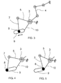
- a rudder 1 supporting a movable contact 2 belonging to a medium voltage electrical protection device according to the invention.
- This rudder 1 is rotated by means of an operating shaft 3 by means of a mechanism comprising a control rod 4.
- This control rod 4 is intended to drive a drive rod 5 of the shaft operating mechanism 3 of the rudder 1 between a first position in which the rudder is in a first so-called line position in which its movable contact 2 is in contact with a fixed contact 6 of the apparatus, and a second position in which this moving contact 2 and this fixed contact 6 are separated.
- the drive rod 5 is driven by the control rod 4 according to the invention by means of an adjusting device.
- This adjusting device comprises a first connecting rod 7 hingedly connected by one, said first 7a, of its ends, to the driving rod 5, and having at another said second end 7b, an axis 8 mounted in a light 9 provided at the so-called first end 10a of a second rod 10 whose second end 10b is hingedly connected to the control rod 4 belonging to the mechanism, this second connecting rod being mounted freely rotatable, between these two ends 10a, 10b, around the operating shaft 3 of the spreader 1.
- the displacement of the axis 8 in the slot 9 is able to cause the rotational movement of the first connecting rod 7, and therefore the driving rod 5 of the operating shaft 3, by means of teeth 11 provided on the one hand, on the driving rod 5, and on the other hand, on the operating shaft 3, which causes a change in the rotational position of the rudder 1.
- This drive rod 5 is a double rod having two parts 5a, 5b opposite connected by folding by one of their ends, these two parts being placed respectively on either side of the first 7 and the second connecting rod. 10 and being traversed by the operating shaft 3.
- This adjusting device also comprises a device for compressing the first connecting rod 7 at the articulation 7b against the second connecting rod 10, by bringing the two parts 10c, 10d of the control rod 10 back towards one another. other.
- This compression system comprises a screw 12 screwed into the shaft 8 forming a nut.
- the screwing of the screw 12 in the axis 8 compresses the rods 10c, 10d and 7 together until a sufficient clamping is obtained to maintain a relative position between the first rod 7 and the second rod 10, and thus prevent the modification of this relative position.
- the lifter 1 is brought into a so-called line position in which the movable contact 2 is in electrical contact with the fixed contact 6, via the opening / closing mechanism comprising the control rod 4. Then, when the two contacts 2.6 are closed, a more precise adjustment is made of the relative position of the two contacts by translating the axis 8 into the light 9 in the direction of one end or the other of the light, and thus driving the first rod 7 in rotation in the counter-clockwise or hourwise direction as one wants to move the drive rod 5 of the operating shaft 3 respectively clockwise or anti-clockwise -Schedule.
- the axis 8 associated with the first link 7 is located at one end of the slot 9, the end farthest from the operating shaft 3. In this position, the angle between the connecting rod 5 drive and the second rod 10 is minimum, which corresponds to a minimum displacement value of the drive rod 5 and therefore of the operating shaft 3 in the counterclockwise direction.
- the axis 8 has been moved towards the other end of the slot 9, which corresponds to a maximum value of the angle between the driving rod 5 and the second connecting rod 10, and therefore to a maximum displacement in rotation of the operating shaft 3 clockwise.
- the holding in position of the spreader 1 is achieved by tightening the screw 12 in the axis 8 so as to bring the two parts of the rod 10 towards each other, and thus obtain the compression of the first rod 7 on the second rod 10 and the locking in position of the axis 8 in the light 9.
- the invention therefore proposes a device for adjusting the rudder 1 of simple design to reduce the dispersion of the blades or pedals in the case of a multipolar device in the closed line position.
Landscapes
- Driving Mechanisms And Operating Circuits Of Arc-Extinguishing High-Tension Switches (AREA)
Applications Claiming Priority (1)
| Application Number | Priority Date | Filing Date | Title |
|---|---|---|---|
| FR1102898A FR2980624B1 (fr) | 2011-09-23 | 2011-09-23 | Appareil de protection electrique comportant un palonnier supportant un contact mobile |
Publications (1)
| Publication Number | Publication Date |
|---|---|
| EP2573782A1 true EP2573782A1 (de) | 2013-03-27 |
Family
ID=46604238
Family Applications (1)
| Application Number | Title | Priority Date | Filing Date |
|---|---|---|---|
| EP12305913A Withdrawn EP2573782A1 (de) | 2011-09-23 | 2012-07-26 | Elektrische Schutzvorrichtung mit einem bewegblichen Kontakt versehenen Schwinghebel |
Country Status (3)
| Country | Link |
|---|---|
| EP (1) | EP2573782A1 (de) |
| CN (1) | CN103021693B (de) |
| FR (1) | FR2980624B1 (de) |
Cited By (2)
| Publication number | Priority date | Publication date | Assignee | Title |
|---|---|---|---|---|
| CN112217013A (zh) * | 2019-07-10 | 2021-01-12 | 东莞市大成智能装备有限公司 | 自动接触式多点供电机构 |
| CN117162121A (zh) * | 2023-09-06 | 2023-12-05 | 昇辉控股有限公司 | 远程控制的可编程的多点按压装置 |
Citations (3)
| Publication number | Priority date | Publication date | Assignee | Title |
|---|---|---|---|---|
| EP0817225A1 (de) * | 1996-06-26 | 1998-01-07 | GEC Alsthom T&D AG | Mehrpoliger Schalter, insbesondere für Hochspannung |
| EP0853326A2 (de) * | 1996-12-20 | 1998-07-15 | ABB SACE S.p.A. | Elektrischer Lastschalter mit Mitteln zur Einstellung der Kontakten |
| EP1124239A2 (de) * | 2000-02-11 | 2001-08-16 | Siemens Aktiengesellschaft | Längeneinstellbare Anordnung zur Verbindung als Koppelelement in Leistungsschaltern |
Family Cites Families (1)
| Publication number | Priority date | Publication date | Assignee | Title |
|---|---|---|---|---|
| FR2921196B1 (fr) * | 2007-09-18 | 2009-12-11 | Schneider Electric Ind Sas | Dispositif de commande de l'ouverture et/ou de la fermeture des contacts electriques dans un appareil electrique et appareil electrique comportant un tel dispositif |
-
2011
- 2011-09-23 FR FR1102898A patent/FR2980624B1/fr active Active
-
2012
- 2012-07-26 EP EP12305913A patent/EP2573782A1/de not_active Withdrawn
- 2012-09-24 CN CN201210359394.0A patent/CN103021693B/zh active Active
Patent Citations (3)
| Publication number | Priority date | Publication date | Assignee | Title |
|---|---|---|---|---|
| EP0817225A1 (de) * | 1996-06-26 | 1998-01-07 | GEC Alsthom T&D AG | Mehrpoliger Schalter, insbesondere für Hochspannung |
| EP0853326A2 (de) * | 1996-12-20 | 1998-07-15 | ABB SACE S.p.A. | Elektrischer Lastschalter mit Mitteln zur Einstellung der Kontakten |
| EP1124239A2 (de) * | 2000-02-11 | 2001-08-16 | Siemens Aktiengesellschaft | Längeneinstellbare Anordnung zur Verbindung als Koppelelement in Leistungsschaltern |
Cited By (3)
| Publication number | Priority date | Publication date | Assignee | Title |
|---|---|---|---|---|
| CN112217013A (zh) * | 2019-07-10 | 2021-01-12 | 东莞市大成智能装备有限公司 | 自动接触式多点供电机构 |
| CN112217013B (zh) * | 2019-07-10 | 2024-05-31 | 东莞市大成智能装备有限公司 | 自动接触式多点供电机构 |
| CN117162121A (zh) * | 2023-09-06 | 2023-12-05 | 昇辉控股有限公司 | 远程控制的可编程的多点按压装置 |
Also Published As
| Publication number | Publication date |
|---|---|
| FR2980624B1 (fr) | 2014-05-16 |
| CN103021693A (zh) | 2013-04-03 |
| FR2980624A1 (fr) | 2013-03-29 |
| CN103021693B (zh) | 2016-02-03 |
Similar Documents
| Publication | Publication Date | Title |
|---|---|---|
| EP2021647B1 (de) | Wegminderungsaktuator, speziell für eine kraftfahrzeugkupplung | |
| FR2783860A1 (fr) | Dispositif pour l'actionnement par moteur electrique ou assiste par moteur electrique d'un hayon arriere ou d'un dispositif de fermeture analogue | |
| FR3011672A1 (fr) | Interrupteur de position | |
| EP2462299B1 (de) | Stellantrieb für kraftfahrzeugtürschloss und zugehörige vorrichtung | |
| FR2921196A1 (fr) | Dispositif de commande de l'ouverture et/ou de la fermeture des contacts electriques dans un appareil electrique et appareil electrique comportant un tel dispositif | |
| EP2756923A1 (de) | Schleifenmesszange, insbesondere für Erde, mit einer festen Spannbacke auf einer festen Halterung und einer schwenkbaren Spannbacke auf der Halterung | |
| EP2573782A1 (de) | Elektrische Schutzvorrichtung mit einem bewegblichen Kontakt versehenen Schwinghebel | |
| FR2594758A1 (fr) | Embrayage, notamment pour vehicules automobiles | |
| EP2605264B1 (de) | Betätigungseinrichtung eines Hilfskontaktes in einer elektrischen Schaltvorrichtung | |
| EP2161730B1 (de) | Steuervorrichtung zum Öffnen und/oder Schließen von Kontakten in einem Elektrogerät | |
| FR2611549A3 (fr) | Cisaille motorisee auto-alimentee | |
| EP2717284B1 (de) | Bedienungsvorrichtung eines elektrischen Schutzschaltgeräts, und diese umfassendes elektrisches Schutzschaltgerät | |
| EP1993115B1 (de) | Steuervorrichtung zur Kontaktherstellung oder -unterbrechung zwischen zwei Teilen und mit dieser Vorrichtung ausgestattetes elektrisches Gerät | |
| FR2470611A1 (fr) | Registre pare-feu | |
| EP2605256A1 (de) | Vorrichtung zur Steuerung der Resetvorrichtungs-Motorisierung der Kontaktschließvorrichtung in einem elektrischen Schutzgerät, und eine solche Vorrichtung enthaltendes Gerät | |
| WO2003054404A1 (fr) | Dispositif d'accouplement a crabot | |
| EP0604330B1 (de) | Modularer Schutzschalter in Verbindung mit einer Fernbedienungseinheit | |
| FR3044162A1 (fr) | Appareil de protection electrique et en particulier disjoncteur electrique moyenne tension | |
| EP0836099B1 (de) | Öffnungsanordnung für Zange insbesondere Strommesszange | |
| FR2914073A1 (fr) | Montre a dispositif de commande et de verrouillage du remontoir | |
| EP1649478A1 (de) | Dreheingriffs-verriegelungsmechanismus für automatische sicherheitsabtrennung | |
| EP0592338A1 (de) | Mechanismus für einen Erdungsschalter | |
| FR2812124A1 (fr) | Sectionneur a couteau avec un systeme de blocage par passage de point mort | |
| EP0036379A1 (de) | Elektrisches Motor-Reduziergetriebe für mittels Handkurbel betätigbare Markisen und Rolläden | |
| EP1680962B1 (de) | Elektrisches Gerät zum Verarbeiten von Lebensmitteln mit verbesserter Sicherheit |
Legal Events
| Date | Code | Title | Description |
|---|---|---|---|
| PUAI | Public reference made under article 153(3) epc to a published international application that has entered the european phase |
Free format text: ORIGINAL CODE: 0009012 |
|
| AK | Designated contracting states |
Kind code of ref document: A1 Designated state(s): AL AT BE BG CH CY CZ DE DK EE ES FI FR GB GR HR HU IE IS IT LI LT LU LV MC MK MT NL NO PL PT RO RS SE SI SK SM TR |
|
| AX | Request for extension of the european patent |
Extension state: BA ME |
|
| 17P | Request for examination filed |
Effective date: 20130718 |
|
| RBV | Designated contracting states (corrected) |
Designated state(s): AL AT BE BG CH CY CZ DE DK EE ES FI FR GB GR HR HU IE IS IT LI LT LU LV MC MK MT NL NO PL PT RO RS SE SI SK SM TR |
|
| GRAP | Despatch of communication of intention to grant a patent |
Free format text: ORIGINAL CODE: EPIDOSNIGR1 |
|
| RIC1 | Information provided on ipc code assigned before grant |
Ipc: H01H 1/34 20060101ALI20140620BHEP Ipc: H01H 1/42 20060101ALI20140620BHEP Ipc: H01H 1/48 20060101ALI20140620BHEP Ipc: H01H 3/46 20060101ALI20140620BHEP Ipc: H01H 3/02 20060101AFI20140620BHEP |
|
| INTG | Intention to grant announced |
Effective date: 20140714 |
|
| RIN1 | Information on inventor provided before grant (corrected) |
Inventor name: TERPEND, SERGE Inventor name: GARAVELLI, JORDANE |
|
| STAA | Information on the status of an ep patent application or granted ep patent |
Free format text: STATUS: THE APPLICATION IS DEEMED TO BE WITHDRAWN |
|
| 18D | Application deemed to be withdrawn |
Effective date: 20141125 |