EP2573883A2 - Capot de recouvrement pour profilé de conduction de courant d'un agencement de boîtier d'alimentation - Google Patents
Capot de recouvrement pour profilé de conduction de courant d'un agencement de boîtier d'alimentation Download PDFInfo
- Publication number
- EP2573883A2 EP2573883A2 EP12184863A EP12184863A EP2573883A2 EP 2573883 A2 EP2573883 A2 EP 2573883A2 EP 12184863 A EP12184863 A EP 12184863A EP 12184863 A EP12184863 A EP 12184863A EP 2573883 A2 EP2573883 A2 EP 2573883A2
- Authority
- EP
- European Patent Office
- Prior art keywords
- contact
- end cap
- contact portion
- current
- face
- Prior art date
- Legal status (The legal status is an assumption and is not a legal conclusion. Google has not performed a legal analysis and makes no representation as to the accuracy of the status listed.)
- Granted
Links
- 239000004020 conductor Substances 0.000 claims abstract description 55
- 229910052751 metal Inorganic materials 0.000 claims abstract description 15
- 239000002184 metal Substances 0.000 claims abstract description 15
- 238000009826 distribution Methods 0.000 claims abstract description 13
- 239000011810 insulating material Substances 0.000 claims description 7
- 230000001681 protective effect Effects 0.000 description 6
- 230000013011 mating Effects 0.000 description 4
- 238000003780 insertion Methods 0.000 description 3
- 230000037431 insertion Effects 0.000 description 3
- 238000000034 method Methods 0.000 description 3
- 238000005452 bending Methods 0.000 description 2
- 238000009434 installation Methods 0.000 description 2
- 238000009413 insulation Methods 0.000 description 2
- 230000007774 longterm Effects 0.000 description 2
- 238000004080 punching Methods 0.000 description 2
- 230000007704 transition Effects 0.000 description 2
- 229910052782 aluminium Inorganic materials 0.000 description 1
- XAGFODPZIPBFFR-UHFFFAOYSA-N aluminium Chemical compound [Al] XAGFODPZIPBFFR-UHFFFAOYSA-N 0.000 description 1
- 239000011248 coating agent Substances 0.000 description 1
- 238000000576 coating method Methods 0.000 description 1
- 238000005260 corrosion Methods 0.000 description 1
- 230000007797 corrosion Effects 0.000 description 1
- 238000007654 immersion Methods 0.000 description 1
- 239000004922 lacquer Substances 0.000 description 1
- 238000004519 manufacturing process Methods 0.000 description 1
- 239000000725 suspension Substances 0.000 description 1
- 210000002105 tongue Anatomy 0.000 description 1
Images



Classifications
-
- H—ELECTRICITY
- H01—ELECTRIC ELEMENTS
- H01R—ELECTRICALLY-CONDUCTIVE CONNECTIONS; STRUCTURAL ASSOCIATIONS OF A PLURALITY OF MUTUALLY-INSULATED ELECTRICAL CONNECTING ELEMENTS; COUPLING DEVICES; CURRENT COLLECTORS
- H01R25/00—Coupling parts adapted for simultaneous co-operation with two or more identical counterparts, e.g. for distributing energy to two or more circuits
- H01R25/14—Rails or bus-bars constructed so that the counterparts can be connected thereto at any point along their length
- H01R25/145—Details, e.g. end pieces or joints
-
- H—ELECTRICITY
- H02—GENERATION; CONVERSION OR DISTRIBUTION OF ELECTRIC POWER
- H02G—INSTALLATION OF ELECTRIC CABLES OR LINES, OR OF COMBINED OPTICAL AND ELECTRIC CABLES OR LINES
- H02G5/00—Installations of bus-bars
- H02G5/04—Partially-enclosed installations, e.g. in ducts and adapted for sliding or rolling current collection
Definitions
- the invention further relates to an end cap for current-carrying profiles, which have a base plate extending in a longitudinal direction and two or more contact webs projecting from the base plate, which extend in the longitudinal direction extend and are each spaced a gap and aligned parallel to each other, wherein the contact webs have longitudinally extending conductors, and wherein the end cap is formed of insulating material and exposed from an end face bearing areas for contacting at least one of the contact webs and / or on the Base plate of a current-carrying profile has, if the end cap is placed with the end face on the front side of the current-carrying profile.
- Such power distribution arrangement also called busbar systems, are used in particular for lighting systems in buildings in order to lay cables for the supply of equipment, in particular of lights or other energy and / or data to be supplied devices cost and visually appealing.
- the installation location of the devices can then be selected flexibly along the mounting rail and varied slightly.
- the devices can thus be contacted in a simple manner with a connector electrically conductive with the cables to a variably definable installation location.
- Such power distribution arrangements also have the advantage that the devices are at the same time mechanically supported on the mounting rail or on the current-carrying profile of the power distribution arrangement.
- US 6,296,498 B1 describes a power distribution arrangement with in a mounting rail profile opposite each other received current guide profiles which extend in the longitudinal direction of the mounting rail profile and extending in the longitudinal direction of the current-carrying profiles extending electrical conductors.
- To connect adjacent DIN rail profiles connecting plug with projecting contact tongues for contacting the associated electrical conductors are provided.
- EP 2 264 363 A1 describes a power distribution assembly having a comb-like current-carrying profile having a plurality of spaced-apart contact lands with electrical conductors integrally molded with a base plate.
- the current-carrying profile is provided at the end faces designated as axial ends with a separate end cap, which covers at least one electrical conductor axially.
- the end cap does not cover the electrical protective conductor (PE conductor), which is arranged free-standing on one of the outer web sections on the outside, axially. As a result, the protective conductor function is ensured even when mounted end cap.
- PE conductor electrical protective conductor
- the connector has metallic connection conductors which are intended to communicate with corresponding conductors of the busbar.
- US 3,688,240 A discloses tails for a power distribution system having bus bar elements.
- the end pieces have a projecting portion, which is intended for insertion into a conductor rail piece.
- a grounding contact is provided, which extends outside the intended section with the conductor connecting contacts and is aligned for contacting a side wall of the busbar.
- the conductors of the busbar are accommodated in a common Isolierstoffhalterung.
- the end cap in this case has at least one contact element, which has both a protruding from the end face conductor contact portion for contacting at least one electrical conductor of a contact web of the current-carrying profile, as well as at least one protruding on an associated side surface side contact portion.
- a simple and reliable protective conductor contacting (PE-contacting) of the current-carrying profile by attaching the end cap on the power supply profile possible.
- the at least one side contact section simply enters into electrically conductive contact with the mounting rail profile in order to produce a protective conductor contact. It is also conceivable that the side contact section with an otherwise mating contact adjacent to the current-carrying profile in electrically conductive contact occurs.
- the production of an electrical contact between the electrical conductor of a contact web contacted with the associated conductor contact section and a mating contact for the side contact section, in particular the mounting rail, is produced in a simple and reliable manner by the side contact sections protruding from an associated side surface of the end cap.
- lateral surface is understood to mean any edge surface on the circumference of the end cap, in particular the lateral side surfaces and upper and lower side surfaces which are perpendicular to the end surface.
- the at least one side contact portion has a resilient element for applying a contact pressure by means of spring force is particularly advantageous.
- an electrically conductive spring contact is made without additional measures for contacting the side contact portion with a mating contact are required.
- the at least one side contact portion is formed from a curvature of a metal sheet.
- the side contact portion is then formed in the manner of a pressure bar contact, wherein the spring force is applied by a single-acting bracket.
- the contact pressure is applied by a fork contact, which has two resilient forks, in which the mating contact, such as the wall of a mounting rail, is inserted while pushing the forks apart.
- the conductor contact portion is in a preferred embodiment as a resilient clip for engaging a contact web with a plant leg to rest against a first surface of a contact web and with a distance to the plant leg parallel thereto extending contact leg to rest against a second surface of the contact web, the first surface opposite, trained.
- the plant leg and the contact leg are connected together.
- the conductor contact portion is formed by means of a spring bow on the contact legs or in the connection between the contact leg and bearing limb for applying a contact pressure to an electrical conductor of a encompassing contact web by spring force.
- the conductor contact portion is formed in this embodiment in the manner of a fork contact, which acts as a resilient clip and engages around the contact web.
- the contact element may have two side contact portions projecting on opposite side surfaces of the end cap. This has the advantage that on both sides on the two opposite side surfaces when sliding the end cap onto the current-carrying profile, an electrically conductive contact, e.g. created with the DIN rail. In this case, in particular for the case of resilient side contact section, the spring forces act opposite to one another and thus ensure reliable and long-term stable electrical contact.
- the contact element has a side contact portion projecting on a side surface of the end cap, which is formed of a sheet metal portion. On the sheet metal portion extends parallel to the side contact portion, a holding web, which rests on a wall portion of the end cap. The side contact section is supported in this way against the wall portion of the end cap to form an abutment and to ensure a reliable contact pressure through the side contact portion.
- the conductor contact portion and the at least one side contact portion of a contact member are preferably formed integrally from a sheet metal member. This can be done for example by punching and / or bending process.
- the sheet metal member preferably has spring characteristics to make a contact pressure by spring force.
- FIG. 1 shows a perspective view of a power distribution arrangement 1, which has a support rail 2, which extends in a longitudinal direction L.
- the support rail 2 is formed from a metal sheet and has a bottom portion 3 and two spaced-apart side portions 4a, 4b.
- the side sections 4a, 4b extend at opposite edge regions of the bottom portion 3 of this bottom portion 3 away.
- an open top support rail 2 is provided, in which at least one current-carrying profile 5 is permanently or detachably installed.
- the current-carrying profile 5 has, in a manner known per se, a base plate and extends upwards from the base plate, i. Transversely away from the base plate away extending contact webs 6.
- the contact webs 6 are arranged parallel to each other with a respective intermediate gap spaced from each other.
- the contact webs 6 have, in a manner known per se, electrical conductors integrated therewith, which likewise extend in the longitudinal direction L and are accessible via the respective gap.
- the power distribution arrangement 1 furthermore has an end cap 7, which is plugged onto an end face of the current-carrying profile 5.
- the end cap 7 is made of insulating material, preferably made of plastic. It has exposed from an end surface contact areas 8, which serve to rest against contact webs 6 of the current-carrying profile 5, to releasably fix the end cap 7 to the current-carrying profile 5.
- the end cap 7 also has a contact element 9.
- the contact element 9 has at least one protruding on an associated side surface 11 side contact portion 10, with which the end cap 7 is electrically contacted as outlined with the support rail 2. In this way, a PE contact (protective conductor contact) between the support rail 2 and current-carrying profile 5 are produced when the end cap 7 is attached to the end face on the current-carrying profile 5.
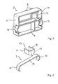
- FIG. 2 leaves a perspective view of the end cap 7 FIG. 1 detect. It is clear that at least on one side of the side surface 11 of the side contact portion 10 in the manner of a resilient pressure bow contact protrudes from the side surface 11 of the end cap 7.
- Recognizable are still two spaced abutment areas 8, which protrude from the end face 12 of the end cap 7.
- a conductor contact portion 13 of the contact element 9 is installed, which electrically contacts an electrical conductor of an associated contact web 6, when the end cap 7 is attached to the end face of the current-carrying profile 5.
- two protruded webs 14 are provided with laterally projecting locking lugs 15, which are provided for immersion in the respective associated column between two contact webs 6 of a current-carrying profile 5. With the help of the locking lugs 15, the end cap 7 can then be clamped to the current-carrying profile 5.
- FIG. 3 leaves a rear view of the end cap 7 FIG. 2 detect. It is clear that in the interior of the end cap formed of electrically insulating plastic 7, a contact element 9 is installed, which has two side surfaces 11 of the end cap protruding side contact portions 10. In this way, the end cap 7 is electrically contacted on both sides with a mounting rail 2, wherein the end cap 7 is clamped by the symmetrical arrangement of the side contact portions 10 self-supporting in the support rail 2.
- FIG. 4 Leaves a perspective view of a first embodiment of a contact element 9 according to the version FIG. 3 detect. It is clear that the contact element 9 is integrally formed from a metal sheet by forming. Punching and / or bending processes are suitable as forming processes.
- the conductor contact portion 13 is formed in the illustrated embodiment as a resilient clip for gripping an associated contact web 6.
- the contact leg 18 extends at a distance from the plant leg 17 parallel thereto and serves to rest on a second surface of the contact web 6, the first surface of the contact web. 6 opposite. In this way, a contact web 6 is received in the gap between the plant leg 17 and contact leg 18. An electrical conductor of the associated contact web 6 is then contacted with the contact leg 8 electrically.
- the contact leg 18 is resilient on the electrical conductor.
- the contact leg 18 is formed as a resilient element which cooperates transversely through a spring bow 19 in the transition to the connecting piece between the contact leg 18 and bearing leg 17.
- the free end of the contact leg 18 is also bent away from the plant leg 17 to allow reliable sliding onto a contact bar 6 without entanglement.
- the free end of the abutment leg 17 could be easily bent away from the contact leg 18 or have an insertion bevel.
- FIG. 5 shows an end cap 7 in the rear view with a second Embodiment of a contact element 9.
- This contact element 9 has a single side contact portion 10 projecting from a side surface 11.
- This side contact portion 10 is formed of a sheet metal portion, on which a holding web 20 extends parallel to the side contact portion 10. The holding web 20 bears against a wall section 21 of the end cap 7 in order to fix the contact element 9 laterally in the end cap 7.
- FIG. 6 lets a perspective view of the second embodiment of the contact element 9 recognize. It is clear that the conductor contact portion 13 is bent transversely from the transition piece between the holding web 20 and side contact portion 10. As a result, the insertion opening for a contact web 6 of the trained as a resilient clamp conductor contact portion 13 is aligned transversely to the spring direction of the side contact portion 10.
- the conductor contact portion 13 in turn has a contact leg 17 and a parallel thereto extending at a distance contact legs 18th
- FIG. 7 leaves a cross-sectional view of the end cap 7 of the FIGS. 1 to 3 and 5 detect. It is clear that the plant areas 8, including the contact areas in the form of webs 14, 15, protrude from an end face 12 of the end cap 7. Visible are also the locking lugs 15 laterally projecting from the webs 14 in the form of barbs with which the end cap 7 can be wedged between two contact webs 6.
- the abutment leg 17 of the conductor contact section 13 is received in a pocket 22 formed from the insulating housing of the end cap 7.
- the plant leg 17 is surrounded on both sides and the front side of a Isolierstoffwand.
- an insulating wall is present on the top and bottom.
- the contact leg 18, however, is received in a one-sided open pocket 23, which is also formed from the insulating material of the housing of the end cap 7.
- This pocket 23 is opened in the direction of the abutment leg 17, so that the contact leg 18 projects out of the pocket 23 due to its curvature. In this way, an electrical contact can be made with an electrical conductor of a contact web 6, which is introduced into the gap between the plant leg 17 and contact legs 18.
- the side contact portion 10 projects laterally beyond the side wall 11 of the insulating housing of the terminal edge 7. He can then be pushed back when plugged into a mounting rail on a power guide profile in the direction of side surface of the end cap 7 to exert a contact pressure by spring force on the support rail 2 and thus to come into electrical contact with the support rail 2.
- the side contact portion 10 may optionally have sharp-edged portions with which a coating of the support rail 2, e.g. Lacquer or corrosion can be penetrated to make a reliable electrical contact.
- a coating of the support rail 2 e.g. Lacquer or corrosion
Landscapes
- Installation Of Indoor Wiring (AREA)
- Connections Arranged To Contact A Plurality Of Conductors (AREA)
- Ignition Installations For Internal Combustion Engines (AREA)
- Train Traffic Observation, Control, And Security (AREA)
- Distribution Board (AREA)
Applications Claiming Priority (1)
| Application Number | Priority Date | Filing Date | Title |
|---|---|---|---|
| DE102011053859.3A DE102011053859B4 (de) | 2011-09-22 | 2011-09-22 | Stromverteileranordnung und Abschlusskappe für Stromführungsprofile hierzu |
Publications (3)
| Publication Number | Publication Date |
|---|---|
| EP2573883A2 true EP2573883A2 (fr) | 2013-03-27 |
| EP2573883A3 EP2573883A3 (fr) | 2014-05-14 |
| EP2573883B1 EP2573883B1 (fr) | 2016-10-19 |
Family
ID=47137506
Family Applications (1)
| Application Number | Title | Priority Date | Filing Date |
|---|---|---|---|
| EP12184863.4A Not-in-force EP2573883B1 (fr) | 2011-09-22 | 2012-09-18 | Capot de recouvrement pour profilé de conduction de courant d'un agencement de boîtier d'alimentation. |
Country Status (2)
| Country | Link |
|---|---|
| EP (1) | EP2573883B1 (fr) |
| DE (1) | DE102011053859B4 (fr) |
Cited By (4)
| Publication number | Priority date | Publication date | Assignee | Title |
|---|---|---|---|---|
| CN109728460A (zh) * | 2017-10-27 | 2019-05-07 | Wago管理有限责任公司 | 分接式插接连接器和用于其的保护接地接触件 |
| US10461483B2 (en) | 2017-11-04 | 2019-10-29 | Architectural busSTRUT Corporation | Strut end condition, end block, and connector |
| CN112868152A (zh) * | 2018-10-25 | 2021-05-28 | Abb瑞士股份有限公司 | 用于使两个层压多相汇流条电互连的设备 |
| WO2026068220A1 (fr) | 2024-09-30 | 2026-04-02 | Signify Holding B.V. | Capuchon d'extrémité |
Families Citing this family (3)
| Publication number | Priority date | Publication date | Assignee | Title |
|---|---|---|---|---|
| DE102016114070B3 (de) * | 2016-07-29 | 2017-11-30 | Wago Verwaltungsgesellschaft Mbh | Stromschienenverbinder und Set aus zwei komplementären Stromschienenverbindern und Metalltrögen mit jeweils darin aufgenommenem Stromführungsprofil |
| DE102016015767B4 (de) | 2016-07-29 | 2022-09-29 | Wago Verwaltungsgesellschaft Mbh | Schutzkappe und Set aus Metalltrog und Schutzkappe |
| DE102018119470A1 (de) * | 2018-08-09 | 2020-02-13 | Trilux Gmbh & Co. Kg | System mit Schutzkappe zur Realisierung einer Leuchte |
Citations (7)
| Publication number | Priority date | Publication date | Assignee | Title |
|---|---|---|---|---|
| DE7118268U (de) | 1971-05-11 | 1972-07-13 | Hoffmeister-Leuchten Kg | Verbindungsstück fur metallische Stromschienen von U-förmigem Querschnitt zur Aufnahme in die Schienenöffnung einsetzbarer Stromabnehmer für ortsveränderliche Stromverbraucher |
| US3688240A (en) | 1970-03-16 | 1972-08-29 | Us Industries Inc | End connector for a power distribution system |
| DE2714467A1 (de) | 1976-04-01 | 1977-10-13 | Nokia Oy Ab | Winkelstueck fuer kontaktschiene |
| DE19859603A1 (de) | 1998-12-23 | 2000-06-29 | Moeller Gmbh | Stromschienensystem |
| US6296498B1 (en) | 2000-01-25 | 2001-10-02 | Universal Electric Corporation | Busbar connector for plug-in busways |
| DE202008002497U1 (de) | 2008-02-22 | 2008-05-08 | Ansorg Gmbh | Aufhängevorrichtung mit einer horizontal anzuordnenden Trägerschiene |
| EP2264363A1 (fr) | 2009-06-16 | 2010-12-22 | RIDI-LEUCHTEN GmbH | Lampe, capuchon terminal et bande lumineuse |
Family Cites Families (5)
| Publication number | Priority date | Publication date | Assignee | Title |
|---|---|---|---|---|
| US3622938A (en) * | 1968-12-10 | 1971-11-23 | Matsushita Electric Works Ltd | Electric power distribution device |
| DE2234435C2 (de) * | 1971-08-03 | 1983-04-28 | Staff GmbH & Co KG, 4920 Lemgo | Überbrückungsadapter für Stromverteilerschienen |
| BE790554A (fr) * | 1971-10-27 | 1973-04-25 | Philips Nv | Raccord pour barres de courant |
| US5480310A (en) * | 1993-10-28 | 1996-01-02 | Raychem Corporation | Connector ground clip |
| GB2330459B (en) * | 1997-10-15 | 2001-10-31 | Ackermann Ltd | Improvements in power tracks |
-
2011
- 2011-09-22 DE DE102011053859.3A patent/DE102011053859B4/de not_active Expired - Fee Related
-
2012
- 2012-09-18 EP EP12184863.4A patent/EP2573883B1/fr not_active Not-in-force
Patent Citations (7)
| Publication number | Priority date | Publication date | Assignee | Title |
|---|---|---|---|---|
| US3688240A (en) | 1970-03-16 | 1972-08-29 | Us Industries Inc | End connector for a power distribution system |
| DE7118268U (de) | 1971-05-11 | 1972-07-13 | Hoffmeister-Leuchten Kg | Verbindungsstück fur metallische Stromschienen von U-förmigem Querschnitt zur Aufnahme in die Schienenöffnung einsetzbarer Stromabnehmer für ortsveränderliche Stromverbraucher |
| DE2714467A1 (de) | 1976-04-01 | 1977-10-13 | Nokia Oy Ab | Winkelstueck fuer kontaktschiene |
| DE19859603A1 (de) | 1998-12-23 | 2000-06-29 | Moeller Gmbh | Stromschienensystem |
| US6296498B1 (en) | 2000-01-25 | 2001-10-02 | Universal Electric Corporation | Busbar connector for plug-in busways |
| DE202008002497U1 (de) | 2008-02-22 | 2008-05-08 | Ansorg Gmbh | Aufhängevorrichtung mit einer horizontal anzuordnenden Trägerschiene |
| EP2264363A1 (fr) | 2009-06-16 | 2010-12-22 | RIDI-LEUCHTEN GmbH | Lampe, capuchon terminal et bande lumineuse |
Cited By (6)
| Publication number | Priority date | Publication date | Assignee | Title |
|---|---|---|---|---|
| CN109728460A (zh) * | 2017-10-27 | 2019-05-07 | Wago管理有限责任公司 | 分接式插接连接器和用于其的保护接地接触件 |
| US10461483B2 (en) | 2017-11-04 | 2019-10-29 | Architectural busSTRUT Corporation | Strut end condition, end block, and connector |
| US10770850B2 (en) | 2017-11-04 | 2020-09-08 | Architectural busSTRUT Corporation | Strut end condition, end block, and connector |
| CN112868152A (zh) * | 2018-10-25 | 2021-05-28 | Abb瑞士股份有限公司 | 用于使两个层压多相汇流条电互连的设备 |
| CN112868152B (zh) * | 2018-10-25 | 2022-07-08 | Abb瑞士股份有限公司 | 用于使两个层压多相汇流条电互连的设备 |
| WO2026068220A1 (fr) | 2024-09-30 | 2026-04-02 | Signify Holding B.V. | Capuchon d'extrémité |
Also Published As
| Publication number | Publication date |
|---|---|
| DE102011053859A1 (de) | 2013-03-28 |
| EP2573883B1 (fr) | 2016-10-19 |
| EP2573883A3 (fr) | 2014-05-14 |
| DE102011053859B4 (de) | 2016-07-28 |
Similar Documents
| Publication | Publication Date | Title |
|---|---|---|
| EP4224635B1 (fr) | Borne de raccordement de conducteur | |
| EP2573883B1 (fr) | Capot de recouvrement pour profilé de conduction de courant d'un agencement de boîtier d'alimentation. | |
| EP2915215B1 (fr) | Ensemble de modules en série pourvu d'un système de bus d'énergie | |
| DE102015114741B4 (de) | Steckverbinder und Set aus Steckverbinder und Verbinderteil | |
| DE102010032383B4 (de) | Stromschienenverbinder und Stromschienensystem mit mindestens zwei benachbarten Stromschienen und einem Stromschienenverbinder | |
| EP3276757B1 (fr) | Connecteur de rail de connexion et kit constitué de deux connecteurs de rail de connexion complémentaires et auges métalliques comprenant respectivement un profilé d'amenée de courant disposé en son sein | |
| EP3292591B1 (fr) | Borne de connexion de conducteur | |
| DE102011056043B4 (de) | Stromschienenabgriffelement | |
| DE102010055789B4 (de) | Stromschienenverbinder und Stromschienensystem mit mindestens zwei benachbarten Stromschienen und einem Stromschienenverbinder | |
| EP3082195B1 (fr) | Dispositif de serrage sans vis pour conducteur electrique | |
| DE102016116968A1 (de) | Stromschienenverbinder | |
| EP0959529A2 (fr) | Unité de connection électrique | |
| EP2573882A2 (fr) | Agencement de boîtier d'alimentation | |
| DE102015010312B4 (de) | Schraubenlose Klemmvorrichtung für elektrische Leiter | |
| EP1475565A2 (fr) | Ensemble eclairage | |
| DE19731411A1 (de) | Haltevorrichtung für elektrische Lüfter, insbesondere Kleinstlüfter | |
| EP1916741B1 (fr) | Dispositif d' interruption et borne de serrage associée | |
| EP2458647B1 (fr) | Borne de connexion anti-foudre, de mise à la terre et de compensation de potentiel | |
| DE102016015767B4 (de) | Schutzkappe und Set aus Metalltrog und Schutzkappe | |
| DE102015113512B3 (de) | Klemmanordnung und Federkraftklemme | |
| DE102008025433A1 (de) | Klemmenanschlußblock | |
| DE102007040422B3 (de) | Anschlusseinheit zum Anschließen eines oder mehrerer Leiter | |
| DE3005619C2 (de) | Elektrische Schraubanschlußklemme zur Verbindung von Einzeldrähten mit Leiterbahnen einer gedruckten Schaltungsplatte | |
| DE29711068U1 (de) | Vorrichtung zum Potentialausgleich | |
| DE10041279C2 (de) | Elektrische Reihenklemme |
Legal Events
| Date | Code | Title | Description |
|---|---|---|---|
| PUAI | Public reference made under article 153(3) epc to a published international application that has entered the european phase |
Free format text: ORIGINAL CODE: 0009012 |
|
| AK | Designated contracting states |
Kind code of ref document: A2 Designated state(s): AL AT BE BG CH CY CZ DE DK EE ES FI FR GB GR HR HU IE IS IT LI LT LU LV MC MK MT NL NO PL PT RO RS SE SI SK SM TR |
|
| AX | Request for extension of the european patent |
Extension state: BA ME |
|
| PUAL | Search report despatched |
Free format text: ORIGINAL CODE: 0009013 |
|
| AK | Designated contracting states |
Kind code of ref document: A3 Designated state(s): AL AT BE BG CH CY CZ DE DK EE ES FI FR GB GR HR HU IE IS IT LI LT LU LV MC MK MT NL NO PL PT RO RS SE SI SK SM TR |
|
| AX | Request for extension of the european patent |
Extension state: BA ME |
|
| RIC1 | Information provided on ipc code assigned before grant |
Ipc: H01R 25/14 20060101AFI20140404BHEP Ipc: H02G 5/04 20060101ALI20140404BHEP |
|
| 17P | Request for examination filed |
Effective date: 20140619 |
|
| RBV | Designated contracting states (corrected) |
Designated state(s): AL AT BE BG CH CY CZ DE DK EE ES FI FR GB GR HR HU IE IS IT LI LT LU LV MC MK MT NL NO PL PT RO RS SE SI SK SM TR |
|
| GRAP | Despatch of communication of intention to grant a patent |
Free format text: ORIGINAL CODE: EPIDOSNIGR1 |
|
| INTG | Intention to grant announced |
Effective date: 20151125 |
|
| GRAS | Grant fee paid |
Free format text: ORIGINAL CODE: EPIDOSNIGR3 |
|
| GRAP | Despatch of communication of intention to grant a patent |
Free format text: ORIGINAL CODE: EPIDOSNIGR1 |
|
| INTG | Intention to grant announced |
Effective date: 20160329 |
|
| GRAA | (expected) grant |
Free format text: ORIGINAL CODE: 0009210 |
|
| AK | Designated contracting states |
Kind code of ref document: B1 Designated state(s): AL AT BE BG CH CY CZ DE DK EE ES FI FR GB GR HR HU IE IS IT LI LT LU LV MC MK MT NL NO PL PT RO RS SE SI SK SM TR |
|
| REG | Reference to a national code |
Ref country code: GB Ref legal event code: FG4D Free format text: NOT ENGLISH |
|
| REG | Reference to a national code |
Ref country code: CH Ref legal event code: EP |
|
| REG | Reference to a national code |
Ref country code: AT Ref legal event code: REF Ref document number: 839063 Country of ref document: AT Kind code of ref document: T Effective date: 20161115 |
|
| REG | Reference to a national code |
Ref country code: IE Ref legal event code: FG4D Free format text: LANGUAGE OF EP DOCUMENT: GERMAN |
|
| REG | Reference to a national code |
Ref country code: DE Ref legal event code: R096 Ref document number: 502012008565 Country of ref document: DE |
|
| REG | Reference to a national code |
Ref country code: NL Ref legal event code: MP Effective date: 20161019 |
|
| REG | Reference to a national code |
Ref country code: LT Ref legal event code: MG4D |
|
| PG25 | Lapsed in a contracting state [announced via postgrant information from national office to epo] |
Ref country code: LV Free format text: LAPSE BECAUSE OF FAILURE TO SUBMIT A TRANSLATION OF THE DESCRIPTION OR TO PAY THE FEE WITHIN THE PRESCRIBED TIME-LIMIT Effective date: 20161019 |
|
| PG25 | Lapsed in a contracting state [announced via postgrant information from national office to epo] |
Ref country code: LT Free format text: LAPSE BECAUSE OF FAILURE TO SUBMIT A TRANSLATION OF THE DESCRIPTION OR TO PAY THE FEE WITHIN THE PRESCRIBED TIME-LIMIT Effective date: 20161019 Ref country code: GR Free format text: LAPSE BECAUSE OF FAILURE TO SUBMIT A TRANSLATION OF THE DESCRIPTION OR TO PAY THE FEE WITHIN THE PRESCRIBED TIME-LIMIT Effective date: 20170120 Ref country code: SE Free format text: LAPSE BECAUSE OF FAILURE TO SUBMIT A TRANSLATION OF THE DESCRIPTION OR TO PAY THE FEE WITHIN THE PRESCRIBED TIME-LIMIT Effective date: 20161019 Ref country code: NO Free format text: LAPSE BECAUSE OF FAILURE TO SUBMIT A TRANSLATION OF THE DESCRIPTION OR TO PAY THE FEE WITHIN THE PRESCRIBED TIME-LIMIT Effective date: 20170119 |
|
| PG25 | Lapsed in a contracting state [announced via postgrant information from national office to epo] |
Ref country code: HR Free format text: LAPSE BECAUSE OF FAILURE TO SUBMIT A TRANSLATION OF THE DESCRIPTION OR TO PAY THE FEE WITHIN THE PRESCRIBED TIME-LIMIT Effective date: 20161019 Ref country code: FI Free format text: LAPSE BECAUSE OF FAILURE TO SUBMIT A TRANSLATION OF THE DESCRIPTION OR TO PAY THE FEE WITHIN THE PRESCRIBED TIME-LIMIT Effective date: 20161019 Ref country code: NL Free format text: LAPSE BECAUSE OF FAILURE TO SUBMIT A TRANSLATION OF THE DESCRIPTION OR TO PAY THE FEE WITHIN THE PRESCRIBED TIME-LIMIT Effective date: 20161019 Ref country code: PL Free format text: LAPSE BECAUSE OF FAILURE TO SUBMIT A TRANSLATION OF THE DESCRIPTION OR TO PAY THE FEE WITHIN THE PRESCRIBED TIME-LIMIT Effective date: 20161019 Ref country code: IS Free format text: LAPSE BECAUSE OF FAILURE TO SUBMIT A TRANSLATION OF THE DESCRIPTION OR TO PAY THE FEE WITHIN THE PRESCRIBED TIME-LIMIT Effective date: 20170219 Ref country code: ES Free format text: LAPSE BECAUSE OF FAILURE TO SUBMIT A TRANSLATION OF THE DESCRIPTION OR TO PAY THE FEE WITHIN THE PRESCRIBED TIME-LIMIT Effective date: 20161019 Ref country code: RS Free format text: LAPSE BECAUSE OF FAILURE TO SUBMIT A TRANSLATION OF THE DESCRIPTION OR TO PAY THE FEE WITHIN THE PRESCRIBED TIME-LIMIT Effective date: 20161019 Ref country code: PT Free format text: LAPSE BECAUSE OF FAILURE TO SUBMIT A TRANSLATION OF THE DESCRIPTION OR TO PAY THE FEE WITHIN THE PRESCRIBED TIME-LIMIT Effective date: 20170220 |
|
| REG | Reference to a national code |
Ref country code: DE Ref legal event code: R097 Ref document number: 502012008565 Country of ref document: DE |
|
| PG25 | Lapsed in a contracting state [announced via postgrant information from national office to epo] |
Ref country code: DK Free format text: LAPSE BECAUSE OF FAILURE TO SUBMIT A TRANSLATION OF THE DESCRIPTION OR TO PAY THE FEE WITHIN THE PRESCRIBED TIME-LIMIT Effective date: 20161019 Ref country code: EE Free format text: LAPSE BECAUSE OF FAILURE TO SUBMIT A TRANSLATION OF THE DESCRIPTION OR TO PAY THE FEE WITHIN THE PRESCRIBED TIME-LIMIT Effective date: 20161019 Ref country code: SK Free format text: LAPSE BECAUSE OF FAILURE TO SUBMIT A TRANSLATION OF THE DESCRIPTION OR TO PAY THE FEE WITHIN THE PRESCRIBED TIME-LIMIT Effective date: 20161019 Ref country code: RO Free format text: LAPSE BECAUSE OF FAILURE TO SUBMIT A TRANSLATION OF THE DESCRIPTION OR TO PAY THE FEE WITHIN THE PRESCRIBED TIME-LIMIT Effective date: 20161019 Ref country code: CZ Free format text: LAPSE BECAUSE OF FAILURE TO SUBMIT A TRANSLATION OF THE DESCRIPTION OR TO PAY THE FEE WITHIN THE PRESCRIBED TIME-LIMIT Effective date: 20161019 |
|
| PLBE | No opposition filed within time limit |
Free format text: ORIGINAL CODE: 0009261 |
|
| STAA | Information on the status of an ep patent application or granted ep patent |
Free format text: STATUS: NO OPPOSITION FILED WITHIN TIME LIMIT |
|
| PG25 | Lapsed in a contracting state [announced via postgrant information from national office to epo] |
Ref country code: SM Free format text: LAPSE BECAUSE OF FAILURE TO SUBMIT A TRANSLATION OF THE DESCRIPTION OR TO PAY THE FEE WITHIN THE PRESCRIBED TIME-LIMIT Effective date: 20161019 Ref country code: BG Free format text: LAPSE BECAUSE OF FAILURE TO SUBMIT A TRANSLATION OF THE DESCRIPTION OR TO PAY THE FEE WITHIN THE PRESCRIBED TIME-LIMIT Effective date: 20170119 Ref country code: IT Free format text: LAPSE BECAUSE OF FAILURE TO SUBMIT A TRANSLATION OF THE DESCRIPTION OR TO PAY THE FEE WITHIN THE PRESCRIBED TIME-LIMIT Effective date: 20161019 |
|
| 26N | No opposition filed |
Effective date: 20170720 |
|
| PG25 | Lapsed in a contracting state [announced via postgrant information from national office to epo] |
Ref country code: SI Free format text: LAPSE BECAUSE OF FAILURE TO SUBMIT A TRANSLATION OF THE DESCRIPTION OR TO PAY THE FEE WITHIN THE PRESCRIBED TIME-LIMIT Effective date: 20161019 |
|
| REG | Reference to a national code |
Ref country code: CH Ref legal event code: PL |
|
| GBPC | Gb: european patent ceased through non-payment of renewal fee |
Effective date: 20170918 |
|
| PG25 | Lapsed in a contracting state [announced via postgrant information from national office to epo] |
Ref country code: MC Free format text: LAPSE BECAUSE OF FAILURE TO SUBMIT A TRANSLATION OF THE DESCRIPTION OR TO PAY THE FEE WITHIN THE PRESCRIBED TIME-LIMIT Effective date: 20161019 |
|
| REG | Reference to a national code |
Ref country code: IE Ref legal event code: MM4A |
|
| REG | Reference to a national code |
Ref country code: BE Ref legal event code: MM Effective date: 20170930 |
|
| PG25 | Lapsed in a contracting state [announced via postgrant information from national office to epo] |
Ref country code: LU Free format text: LAPSE BECAUSE OF NON-PAYMENT OF DUE FEES Effective date: 20170918 |
|
| REG | Reference to a national code |
Ref country code: FR Ref legal event code: ST Effective date: 20180531 |
|
| PG25 | Lapsed in a contracting state [announced via postgrant information from national office to epo] |
Ref country code: LI Free format text: LAPSE BECAUSE OF NON-PAYMENT OF DUE FEES Effective date: 20170930 Ref country code: CH Free format text: LAPSE BECAUSE OF NON-PAYMENT OF DUE FEES Effective date: 20170930 Ref country code: IE Free format text: LAPSE BECAUSE OF NON-PAYMENT OF DUE FEES Effective date: 20170918 Ref country code: GB Free format text: LAPSE BECAUSE OF NON-PAYMENT OF DUE FEES Effective date: 20170918 |
|
| PG25 | Lapsed in a contracting state [announced via postgrant information from national office to epo] |
Ref country code: BE Free format text: LAPSE BECAUSE OF NON-PAYMENT OF DUE FEES Effective date: 20170930 Ref country code: FR Free format text: LAPSE BECAUSE OF NON-PAYMENT OF DUE FEES Effective date: 20171002 |
|
| PG25 | Lapsed in a contracting state [announced via postgrant information from national office to epo] |
Ref country code: MT Free format text: LAPSE BECAUSE OF FAILURE TO SUBMIT A TRANSLATION OF THE DESCRIPTION OR TO PAY THE FEE WITHIN THE PRESCRIBED TIME-LIMIT Effective date: 20161019 |
|
| REG | Reference to a national code |
Ref country code: AT Ref legal event code: MM01 Ref document number: 839063 Country of ref document: AT Kind code of ref document: T Effective date: 20170918 |
|
| PG25 | Lapsed in a contracting state [announced via postgrant information from national office to epo] |
Ref country code: AT Free format text: LAPSE BECAUSE OF NON-PAYMENT OF DUE FEES Effective date: 20170918 |
|
| PG25 | Lapsed in a contracting state [announced via postgrant information from national office to epo] |
Ref country code: HU Free format text: LAPSE BECAUSE OF FAILURE TO SUBMIT A TRANSLATION OF THE DESCRIPTION OR TO PAY THE FEE WITHIN THE PRESCRIBED TIME-LIMIT; INVALID AB INITIO Effective date: 20120918 |
|
| PG25 | Lapsed in a contracting state [announced via postgrant information from national office to epo] |
Ref country code: CY Free format text: LAPSE BECAUSE OF NON-PAYMENT OF DUE FEES Effective date: 20161019 |
|
| PG25 | Lapsed in a contracting state [announced via postgrant information from national office to epo] |
Ref country code: MK Free format text: LAPSE BECAUSE OF FAILURE TO SUBMIT A TRANSLATION OF THE DESCRIPTION OR TO PAY THE FEE WITHIN THE PRESCRIBED TIME-LIMIT Effective date: 20161019 |
|
| PG25 | Lapsed in a contracting state [announced via postgrant information from national office to epo] |
Ref country code: TR Free format text: LAPSE BECAUSE OF FAILURE TO SUBMIT A TRANSLATION OF THE DESCRIPTION OR TO PAY THE FEE WITHIN THE PRESCRIBED TIME-LIMIT Effective date: 20161019 |
|
| PG25 | Lapsed in a contracting state [announced via postgrant information from national office to epo] |
Ref country code: AL Free format text: LAPSE BECAUSE OF FAILURE TO SUBMIT A TRANSLATION OF THE DESCRIPTION OR TO PAY THE FEE WITHIN THE PRESCRIBED TIME-LIMIT Effective date: 20161019 |
|
| PGFP | Annual fee paid to national office [announced via postgrant information from national office to epo] |
Ref country code: DE Payment date: 20210929 Year of fee payment: 10 |
|
| REG | Reference to a national code |
Ref country code: DE Ref legal event code: R119 Ref document number: 502012008565 Country of ref document: DE |
|
| PG25 | Lapsed in a contracting state [announced via postgrant information from national office to epo] |
Ref country code: DE Free format text: LAPSE BECAUSE OF NON-PAYMENT OF DUE FEES Effective date: 20230401 |