EP2574513A1 - Bremsflüssigkeitdrucksteuerungsvorrichtung für ein Fahrzeug - Google Patents
Bremsflüssigkeitdrucksteuerungsvorrichtung für ein Fahrzeug Download PDFInfo
- Publication number
- EP2574513A1 EP2574513A1 EP12186114A EP12186114A EP2574513A1 EP 2574513 A1 EP2574513 A1 EP 2574513A1 EP 12186114 A EP12186114 A EP 12186114A EP 12186114 A EP12186114 A EP 12186114A EP 2574513 A1 EP2574513 A1 EP 2574513A1
- Authority
- EP
- European Patent Office
- Prior art keywords
- fluid pressure
- allowable differential
- wheel
- friction coefficient
- road
- Prior art date
- Legal status (The legal status is an assumption and is not a legal conclusion. Google has not performed a legal analysis and makes no representation as to the accuracy of the status listed.)
- Granted
Links
Images


Classifications
-
- B—PERFORMING OPERATIONS; TRANSPORTING
- B60—VEHICLES IN GENERAL
- B60T—VEHICLE BRAKE CONTROL SYSTEMS OR PARTS THEREOF; BRAKE CONTROL SYSTEMS OR PARTS THEREOF, IN GENERAL; ARRANGEMENT OF BRAKING ELEMENTS ON VEHICLES IN GENERAL; PORTABLE DEVICES FOR PREVENTING UNWANTED MOVEMENT OF VEHICLES; VEHICLE MODIFICATIONS TO FACILITATE COOLING OF BRAKES
- B60T8/00—Arrangements for adjusting wheel-braking force to meet varying vehicular or ground-surface conditions, e.g. limiting or varying distribution of braking force
- B60T8/17—Using electrical or electronic regulation means to control braking
- B60T8/176—Brake regulation specially adapted to prevent excessive wheel slip during vehicle deceleration, e.g. ABS
- B60T8/1764—Regulation during travel on surface with different coefficients of friction, e.g. between left and right sides, mu-split or between front and rear
-
- B—PERFORMING OPERATIONS; TRANSPORTING
- B60—VEHICLES IN GENERAL
- B60T—VEHICLE BRAKE CONTROL SYSTEMS OR PARTS THEREOF; BRAKE CONTROL SYSTEMS OR PARTS THEREOF, IN GENERAL; ARRANGEMENT OF BRAKING ELEMENTS ON VEHICLES IN GENERAL; PORTABLE DEVICES FOR PREVENTING UNWANTED MOVEMENT OF VEHICLES; VEHICLE MODIFICATIONS TO FACILITATE COOLING OF BRAKES
- B60T2210/00—Detection or estimation of road or environment conditions; Detection or estimation of road shapes
- B60T2210/10—Detection or estimation of road conditions
- B60T2210/12—Friction
- B60T2210/124—Roads with different friction levels
Definitions
- the present invention relates to a vehicle brake fluid pressure control apparatus including: a fluid pressure adjusting unit capable of performing adjustment of individually increasing and decreasing brake fluid pressures acting respectively on wheel brakes for front wheels and wheel brakes for rear wheels so as to prevent the front wheels and the rear wheels from being locked during braking; and allowable differential pressure setting means for setting allowable differential pressures allowable between the brake fluid pressures of the wheel brakes for the left and right coaxial front wheels and between the brake fluid pressures of the wheel brakes for the left and right coaxial rear wheels, the operation of the fluid pressure adjusting unit being controlled in such a way that each of the differential pressures between the brake fluid pressures of the wheel brakes for the left and right coaxial front wheels and between the brake fluid pressures of the wheel brakes for the left and right coaxial rear wheels is equal to or lower than a corresponding one of the allowable differential pressures set by the allowable differential pressure setting means.
- a vehicle brake fluid pressure control apparatus configured to perform anti-lock brake control independently for wheel brakes for left and right coaxial front wheels and left and right coaxial rear wheels is known from Japanese Patent Application Laid-open No. 2007-55583 .
- an allowable differential pressure selected from allowable differential pressures calculated from a vehicle speed, a lateral acceleration, and fluid pressures of the wheel brakes of the coaxial wheels is set by allowable differential pressure setting means, and a differential pressure larger than the selected differential pressure is prevented from occurring between the brake fluid pressures of the left and right wheel brakes.
- the present invention has been made in view of the circumstances described above and an object thereof is to provide a vehicle brake fluid pressure control apparatus capable of obtaining an allowable differential pressure stably matching a friction coefficient of a road surface.
- a vehicle brake fluid pressure control apparatus including: a fluid pressure adjusting unit capable of performing adjustment of individually increasing and decreasing brake fluid pressures acting respectively on wheel brakes for front wheels and wheel brakes for rear wheels so as to prevent the front wheels and the rear wheels from being locked during braking; and allowable differential pressure setting means for setting allowable differential pressures allowable between the brake fluid pressures of the wheel brakes for the left and right coaxial front wheels and between the brake fluid pressures of the wheel brakes for the left and right coaxial rear wheels, the operation of the fluid pressure adjusting unit being controlled in such a way that each of the differential pressures between the brake fluid pressures of the wheel brakes for the left and right coaxial front wheels and between the brake fluid pressures of the wheel brakes for the left and right coaxial rear wheels is equal to or lower than a corresponding one of the allowable differential pressures set by the allowable differential pressure setting means, wherein the vehicle brake fluid pressure control apparatus comprises fluid pressure acquiring means for acquiring a
- each allowable differential pressure matching the road surface friction coefficient is set based on at least the lock fluid pressure of the wheel brake of the wheel coaxial with and other than the wheel being the control target, the lock fluid pressure being the fluid pressure at which pressure decrease by an anti-lock brake control is started. Accordingly, compared to the conventional case in which the fluid pressure of the wheel brake of the coaxial wheel is used as a component corresponding to the friction coefficient of the road surface, it is possible to suppress fluctuation in the allowable differential pressure in such a way that hunting caused by the effects of fluid pressure change due to increase and decrease in the brake fluid pressure in the anti-lock brake control is prevented from occurring. Hence, the allowable differential pressures stably matching the friction coefficient of the road surface can be set.
- the fluid pressure acquiring means calculates the lock fluid pressure on the basis of an output fluid pressure of a master cylinder common to the wheel brakes and drive electric currents of electromagnetic valves forming part of the fluid pressure adjusting unit.
- the lock fluid pressure can be appropriately acquired without using sensors or the like.
- the allowable differential pressure setting means has a map in which the allowable differential pressures are set in advance for the lock fluid pressure and sets the allowable differential pressures matching the road surface friction coefficient on the basis of the map.
- each allowable differential pressure can be easily set to a value suitable for the friction coefficient of the road surface by using the map set based on experiments, simulations, and the like.
- fluid pressure acquiring means is capable of acquiring the fluid pressure of the wheel brake of the wheel coaxial with and other than the wheel being the control target
- the allowable differential pressure setting means sets each of the allowable differential pressures matching the road surface friction coefficient on the basis of the larger one of the fluid pressure of the wheel other than the wheel being the control target and the lock fluid pressure acquired by the fluid pressure acquiring means.
- the allowable differential pressures matching the road surface friction coefficient can be set more accurately.
- the allowable differential pressure setting means sets the allowable differential pressures based on the lock fluid pressure in a period except for a period from a start of pressure decrease in a start of the anti-lock brake control to a start of pressure increase.
- the allowable differential pressure matching the road surface friction coefficient is not set in the period from the start of pressure decrease in the start of the anti-lock brake control to the start of pressure increase.
- the allowable differential pressures based on the lock fluid pressure are thus not set in a period in which the lock fluid pressure may overshoot due to full braking. Accordingly, the reliability can be improved.
- the apparatus further comprises estimated vehicle body deceleration calculating means for calculating an estimated vehicle body deceleration, wherein the allowable differential pressure setting means sets a value of the larger one of the allowable differential pressure set based on the estimated vehicle body deceleration and the allowable differential pressure set based on the lock fluid pressure as each of the allowable differential pressures matching the road surface friction coefficient.
- the allowable differential pressures are set in consideration of the estimated vehicle body deceleration as a component corresponding to the friction coefficient of the road surface. Accordingly, the allowable differential pressures more accurately matching the friction coefficient of the running road surface can be obtained.
- the apparatus comprises: split road judging means for judging whether a road is a split road in which fiction coefficients of contact road surfaces of left and right wheels differ greatly from each other; and low-friction coefficient road judging means for judging whether a road is a low-friction coefficient road in which a friction coefficient of a road surface is lower than a predetermined friction coefficient, wherein application of the allowable differential pressures matching the road surface friction coefficient is prohibited when a judgment result of the split road judging means is the split road or when a judgment result of the low-friction coefficient road judging means is the low-friction coefficient road.
- the apparatus further comprises estimated vehicle body deceleration calculating means for calculating an estimated vehicle body deceleration of a vehicle, wherein the allowable differential pressure setting means sets a value of the larger one of the allowable differential pressure based on the estimated vehicle body deceleration and the allowable differential pressure based on the lock fluid pressure as each of the allowable differential pressures matching the road surface friction coefficient.
- the allowable differential pressures matching the friction coefficient of the road surface can be accurately set.
- the split road judging means judges that the road is the split road when an independent control using the allowable differential pressure is continuously executed for a predetermined time or more in any of the wheel brakes for the left and right front wheels.
- the road is judged as the split road when the independent control using the allowable differential pressures continues for the predetermined time or more in any of the left and right front wheels.
- the split road judging means judges that the road is the split road when the brake fluid pressure of the wheel being the control target is higher than the lock fluid pressure of the wheel brake of the wheel coaxial with and other than the wheel being the control target by a predetermined value or more.
- the road is judged as the split road when the brake fluid pressure of the wheel being the control target is higher than the lock fluid pressure of the wheel brake of the wheel coaxial with and other than the wheel being the control target by the predetermined value or more.
- the low-friction coefficient road judging means judges that the road is the low-friction coefficient road when a change amount of the estimated vehicle body deceleration calculated by the estimated vehicle body deceleration calculating means is lower than a defined value.
- the road is judged as the low-friction coefficient road when the change amount of the estimated vehicle body deceleration is lower than the defined value.
- the apparatus further comprises ⁇ jump judging means for judging whether it is a ⁇ jump state in which a friction coefficient of a running road surface changes from a high friction coefficient to a lower friction coefficient side by a predetermined value or more, wherein the allowable differential pressure setting means stops setting of the allowable differential pressures matching the road surface friction coefficient when a judgment result of the ⁇ jump judging means is the ⁇ jump state.
- ⁇ jump judging means for judging whether it is a ⁇ jump state in which a friction coefficient of a running road surface changes from a high friction coefficient to a lower friction coefficient side by a predetermined value or more
- the allowable differential pressure setting means stops setting of the allowable differential pressures matching the road surface friction coefficient when a judgment result of the ⁇ jump judging means is the ⁇ jump state.
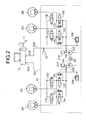
- a vehicle V includes: left and right coaxial front wheels WA and WB to which a driving force of an engine E is transmitted via a transmission T; and left and right coaxial rear wheels WC and WD.
- a brake pedal 11 operated by a driver is connected to a master cylinder M.
- Wheel brakes BA, BB, BC, and BD which operate by actions of brake fluid pressures are provided respectively in the front wheels WA and WB and the rear wheels WC and WD.
- the master cylinder M is connected to the wheel brakes BA to BD via a fluid pressure adjusting unit 12.
- the fluid pressure adjusting unit 12 is capable of performing adjustment of individually increasing and decreasing the brake fluid pressures acting on the wheel brakes BA to BD to prevent the wheels from locking during braking.
- the operation of the fluid pressure adjusting unit 12 is controlled by a fluid pressure control apparatus 13.
- the fluid pressure control apparatus 13 receives: signals from wheel speed sensors SA, SB, SC, and SD attached respectively to the left and right front wheels WA and WB and the left and right rear wheels WC and WD; a signal from a pressure sensor SP detecting a braking pressure outputted from the master cylinder M; and a signal from a lateral acceleration sensor SL detecting a lateral acceleration acting on the vehicle V.
- the fluid pressure control apparatus 13 controls the operation of the fluid pressure adjusting unit 12 on the basis of the signals from the respective sensors SA to SD, SP, and SL.
- the fluid pressure adjusting unit 12 includes: normally-open electromagnetic valves 15A to 15D respectively for the wheel brake BA for the left front wheel WA, the wheel brake BB for the right front wheel WB, the wheel brake BC for the left rear wheel WC, and the wheel brake BD for the right rear wheel WD; check valves 16A to 16D connected in parallel respectively with the normally-open electromagnetic valves 15A to 15D; normally-closed electromagnetic valves 17A to 17D respectively for the wheel brakes BA to BD; a first reservoir 18A for a first output fluid pressure passage 24A leading to a first output port 23A out of the first output port 23A and a second output port 23B included in the master cylinder M; a second reservoir 18B for a second output fluid pressure passage 24B leading to the second output port 23B of the master cylinder M; first and second pumps 19A and 19B whose suction sides are connected respectively to the first and second reservoirs 18A and 18B and whose discharge sides are connected respectively to the first and second output fluid pressure passages 24
- the normally-open electromagnetic valves 15A and 15D are each provided between the first output fluid pressure passage 24A and a corresponding one of the wheel brake BA for the left front wheel WA and the wheel brake BD for the right rear wheel WD.
- the normally-open electromagnetic valves 15B and 15C are each provided between the second output fluid pressure passage 24B and a corresponding one of the wheel brake BB for the right front wheel WB and the wheel brake BC for the left rear wheel WC.
- check valves 16A to 16D are connected in parallel respectively with the normally-open electromagnetic valves 15A to 15D to allow a brake fluid to flow to the master cylinder M from the wheel brakes BA to BD.
- the normally-closed electromagnetic valves 17A and 17D are each provided between the first reservoir 18A and a corresponding one of the wheel brake BA for the left front wheel WA and the wheel brake BD for the right rear wheel WD.
- the normally-closed electromagnetic valves 17B and 17C are each provided between the second reservoir 18B and a corresponding one of the wheel brake BB for the right front wheel WB and the wheel brake BC for the left rear wheel WC.
- the fluid pressure adjusting unit 12 configured as described above causes the master cylinder M and the wheel brakes BA to BD to communicate with each other while the wheel brakes BA to BD are isolated from the first and second reservoirs 18A and 18B.
- the normally-open electromagnetic valves 15A to 15D are demagnetized and opened while the normally-closed electromagnetic valves 17A to 17D are demagnetized and closed.
- a brake fluid pressure outputted from the first output port 23A of the master cylinder M acts on the wheel brake BA for the left front wheel WA via the normally-open electromagnetic valve 15A and also acts on the wheel brake BD for the right rear wheel WD via the normally-open electromagnetic valve 15D.
- a brake fluid pressure outputted from the second output port 23B of the master cylinder M acts on the wheel brake BB for the right front wheel WB via the normally-open electromagnetic valve 15B and also acts on the wheel brake BC for the left rear wheel WC via the normally-open electromagnetic valve 15C.
- the fluid pressure adjusting unit 12 isolates the master cylinder M and the wheel brakes BA to BD from each other and also causes the wheel brakes BA to BD and the reservoirs 18A and 18B to communicate with each other at portions corresponding to the wheel in the almost-locking state.
- a normally-open electromagnetic valve corresponding to the wheel in the almost-locking state among the normally-open electromagnetic valves 15A to 15D is magnetized and closed while a normally-closed electromagnetic valve corresponding to the wheel in the almost-locking state is magnetized and opened.
- part of the brake fluid pressure of the wheel in the almost-locking state is absorbed by the first reservoir 18A or the second reservoir 18B and the brake fluid pressure of the wheel in the almost-locking state is thereby decreased.
- the fluid pressure adjusting unit 12 is set to a state where the wheel brakes BA to BD are isolated from the master cylinder M and the reservoirs 18A and 18B. Specifically, the normally-open electromagnetic valves 15A to 15D are magnetized and closed while the normally-closed electromagnetic valves 17A to 17D are demagnetized and closed. Furthermore, when the brake fluid pressure is to be increased, the normally-open electromagnetic valves 15A to 15D are demagnetized and opened while the normally-closed electromagnetic valves 17A to 17D are demagnetized and closed.
- Efficient braking without the wheels locking can be achieved by controlling demagnetization and magnetization of the normally-open electromagnetic valves 15A to 15D and the normally-closed electromagnetic valves 17A to 17D as described above.
- the electric motor 20 rotationally operates and the first and second pumps 19A and 19B are driven by the operation of the electric motor 20. Accordingly, the brake fluid absorbed in the first and second reservoirs 18A and 18B is suctioned by the first and second pumps 19A and 19B and is then circulated to the first and second output fluid pressure passages 24A and 24B via the first and second dampers 21A and 21B.
- the brake fluid can be returned to the master cylinder M by this circulation of the brake fluid.
- pulsation of discharge pressures of the first and second pumps 19A and 19B are suppressed by the actions of the first and second dampers 21A and 21B and the first and second orifices 22A and 22B.
- the operation feeling of the brake pedal 11 is thus not adversely affected by the circulation.
- the fluid pressure control apparatus 13 controlling the operation of the fluid pressure adjusting unit 12 can execute, in addition to the anti-lock brake control, a differential pressure control in which the difference between the brake fluid pressures of the wheel brakes BA and BB for the left and right coaxial front wheels WA and WB and the difference between the brake fluid pressures of the wheel brakes BC and BD for the left and right coaxial rear wheels WC and WD are controlled to be within allowable differential pressures.
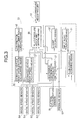
- the fluid pressure control apparatus 13 includes: estimated vehicle body speed calculating means 25 for calculating an estimated vehicle body speed from wheel speeds obtained by the wheel speed sensors SA to SD; estimated vehicle body deceleration calculating means 26 for calculating an estimated vehicle body deceleration on the basis of the estimated vehicle body speed calculated by the estimated vehicle body speed calculating means 25; allowable differential pressure setting means 27 for setting allowable differential pressures allowable between the brake fluid pressures of the wheel brakes BA and BB for the left and right coaxial front wheels WA and WB and between the brake fluid pressures of the wheel brakes BC and BD for the left and right coaxial rear wheels WC and WD; fluid pressure adjusting driving means 28 for determining a control amount on the basis of the allowable differential pressures set by the allowable differential pressure setting means 27, an output fluid pressure of the master cylinder M detected by the pressure sensor SP, the wheel speeds obtained by the wheel speed sensors SA to SD, and the estimated vehicle body speed calculated by the estimated vehicle body speed calculating means 25 and for causing the fluid pressure adjusting unit
- the estimated vehicle body speed calculating means 25 calculates the estimated vehicle body speed on the basis of, for example, a highest wheel speed being the wheel speed with the greatest value among the wheel speeds obtained by the wheel speed sensors SA to SD.
- the estimated vehicle body speed calculating means 25 corrects the highest wheel speed by using predetermined acceleration and deceleration to obtain such an estimated vehicle speed that the largest acceleration and the largest deceleration are respectively the predetermined acceleration and deceleration.
- the estimated vehicle body deceleration calculating means 26 calculates the estimated vehicle body deceleration as an inclination of a straight line connecting peak values of the estimated vehicle body speed.
- the fluid pressure acquiring means 29 acquires the wheel brake fluid pressure and the lock fluid pressure of the wheel coaxial with and other than the wheel being the control target, on the basis of the output fluid pressure of the master cylinder M common to the multiple wheel brakes BA to BD and drive electric currents of the electromagnetic valves forming part of the fluid pressure adjusting unit 12, i.e. the normally-open electromagnetic valves 15A to 15D and the normally-closed electromagnetic valves 17A to 17D.
- the output fluid pressure of the master cylinder M is inputted into the fluid pressure acquiring means 29 from the pressure sensor SP and signals representing the drive electric currents of the normally-open electromagnetic valves 15A to 15D and the normally-closed electromagnetic valves 17A to 17D are inputted into the fluid pressure acquiring means 29 from the fluid pressure adjusting driving means 28.
- the allowable differential pressure setting means 27 sets each of the allowable differential pressures by selecting the largest one of a vehicle body speed component determined depending on the estimated vehicle body speed, a lateral acceleration component determined depending on the lateral acceleration, and a friction coefficient component determined depending on the friction coefficient of the running road surface.
- the estimated vehicle body speed obtained by the estimated vehicle body speed calculating means 25, the estimated vehicle body deceleration obtained by the estimated vehicle body deceleration calculating means 26, the lateral acceleration obtained by the lateral acceleration sensor SL, the lock fluid pressure obtained by the fluid pressure acquiring means 29, and the fluid pressure of the coaxial wheel obtained by the fluid pressure acquiring means 29 are inputted into the allowable differential pressure setting means 27.
- the allowable differential pressure setting means 27 has a map in which the allowable differential pressures are set as shown in FIG. 5 depending on the estimated vehicle body speed on the basis of experiments, simulations, and the like for each of the pair of the front wheels and the pair of the rear wheels, the map being set as the vehicle body speed component determined depending on the estimated vehicle body speed calculated by the estimated vehicle body speed calculating means 25.
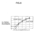
- the allowable differential pressure setting means 27 also has a map in which the allowable differential pressures are set as shown in FIG. 6 depending on the lateral acceleration on the basis of experiments, simulations, and the like for each of the pair of the front wheels and the pair of the rear wheels, the map being set as the lateral acceleration component determined depending on the lateral acceleration detected by the lateral acceleration sensor SL.
- the allowable differential pressure setting means 27 selects the value of the larger one of a lock fluid pressure component and an estimated vehicle body deceleration component as the friction coefficient component determined depending on the friction coefficient of the running road surface and uses it as the friction coefficient component,
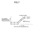
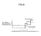
- the allowable differential pressure setting means 27 has a map in which the allowable differential pressures are set as shown in FIG. 7 depending on the lock fluid pressure on the basis of experiments, simulations, and the like for each of the pair of the front wheels and the pair of the rear wheels, the map being set as the lock fluid pressure component.
- the allowable differential pressure setting means 27 also has a map in which the allowable differential pressures are set as shown in FIG.
- the allowable differential pressure setting means 27 sets high select values of the allowable differential pressures obtained from these maps as the allowable differential pressures matching a road surface friction coefficient.
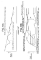
- the fluid pressure acquiring means 29 thus starts acquiring the lock fluid pressure from a time t1 being a time at which the pressure increase in the first cycle of the anti-lock brake control is started. This enables the lock fluid pressure to be acquired accurately.
- the allowable differential pressure setting means 27 selects the value of the larger one of the lock fluid pressure obtained by the fluid pressure acquiring means 29 and the brake fluid pressure of the coaxial wheel. In a period between times t2 to t3 in which the brake fluid pressure of the coaxial wheel is larger than the lock fluid pressure, the allowable differential pressure setting means 27 uses the brake fluid pressure of the coaxial wheel as the lock fluid pressure.
- the allowable differential pressure setting means 27 does not set the allowable differential pressures based on the lock fluid pressure during a period from the start of pressure decrease by the start of the anti-lock brake control to the start of pressure increase.
- the estimated vehicle body deceleration calculating means 26 cannot accurately calculate the estimated vehicle body deceleration used to set the allowable differential pressures matching the friction coefficient of the road surface, in an initial stage of the anti-lock brake control. Accordingly, the allowable differential pressure setting means 27 sets the allowable differential pressures based on the estimated vehicle body speed after a control cycle of decreasing, maintaining, and increasing the brake fluid pressure is repeated at least two times in the anti-lock brake control.
- the split road judging means 31 judges that a road is the split road when an independent control using the allowable differential pressures is continuously executed for any of the left and right front wheels for a predetermined time or longer on the basis of the signals from the fluid pressure adjusting driving means 28 and also judges that the road is the split road when the brake fluid pressure of the wheel being the control target is higher than the lock fluid pressure of the wheel brake of the wheel coaxial with and other than the wheel being the control target by a predetermined value or more.
- a state where the differential pressure between the wheel brakes BA and BB for the left and right front wheels is continuously occurring for the predetermined time or more can be estimated as the split road and the split road judging means 31 judges that the road is the split road in such a state.
- the low-friction coefficient road judging means 32 judges that a road is the low-friction coefficient road when the estimated vehicle body deceleration calculated by the estimated vehicle body deceleration calculating means 26 is lower than a defined value and also judges that the road is the low-friction coefficient road when the lock fluid pressure of any of the wheel brakes BA and BB for the left and right front wheels WA and WB is smaller than a predetermined valve. Specifically, the lock fluid pressure becomes low on a road surface having a low friction coefficient as shown in FIG. 10B and it can be judged that the road is the low friction coefficient road when the lock fluid pressure is lower than the predetermined value.
- the ⁇ jump judging means 33 judges that it is the ⁇ jump state when a pressure decrease amount in the anti-lock brake control of any of the wheel brakes BA and BB for the left and right front wheels WA and WB increases by a predetermined amount or more from the pressure decrease amount in the previous cycle.
- the allowable differential pressure setting means 27 stops the setting of the allowable differential pressures matching the road surface friction coefficient and set each allowable differential pressure by selecting the larger one of the vehicle body speed component determined depending on the estimated vehicle speed and the lateral acceleration component determined depending on the lateral acceleration.
- the application of the allowable differential pressures matching the road surface friction coefficients is prohibited in at least the wheel brakes BC and BD for the left and right rear wheels WC and WD when the low-friction coefficient road judging means 32 judges that the road is the low-friction coefficient road on the basis of the lock fluid pressures of the wheel brakes BA and BB for the left and right front wheels WA and WB.
- the application of the allowable differential pressures matching the road surface friction coefficients is prohibited in at least the wheel brakes BC and BD for the rear wheels WC and WD when the lock fluid pressure of any of the wheel brakes BA and BB for the left and right front wheels WA and WB, which are acquired by the fluid pressure acquiring means 29, is equal to or lower than the predetermined value from which the road can be judged to have a low friction coefficient.
- the allowable differential pressure setting means 27 sets each allowable differential pressure by selecting the largest one of the vehicle speed component determined depending on the estimated vehicle body speed, the lateral acceleration component determined depending on the lateral acceleration, and the friction coefficient component determined depending on the friction coefficient of the running road surface.
- the allowable differential pressure setting means 27 determines each allowable differential pressure matching the road surface friction coefficient by selecting a value of the larger one of the estimated vehicle body deceleration component and the lock fluid pressure component.
- the allowable differential pressure setting means 27 sets each allowable differential pressure matching the road surface friction coefficient on the basis of the estimated vehicle body deceleration calculated by the estimated vehicle body deceleration calculating means 26 as the estimated vehicle body deceleration component and sets the allowable differential pressure matching the road surface friction coefficient on the basis of the lock fluid pressure of the coaxial wheel acquired by the fluid pressure acquiring means 29 as the lock fluid pressure component.
- the allowable differential pressures matching the road surface friction coefficient are set based on the estimated vehicle body deceleration, it is possible to accurately judge whether the road surface has a high friction coefficient or a low friction coefficient and to set larger allowable fluid differential pressures between the brake fluid pressures of the wheel brakes BA and BB for the left and right coaxial front wheels WA and WB and between the brake fluid pressures of the wheel brakes BC and BD for the left and right rear wheels WC and WD on the road surface having the high friction coefficient which is a stable running road surface, compared to the conventional case in which the brake fluid pressure of the wheel coaxial with the wheel being the control target is used as the component corresponding to the friction coefficient of the road surface. Accordingly, the control efficiency of a left-right independent control can be improved.
- each allowable differential pressure matching the road surface friction coefficient is set based on the lock fluid pressure of the coaxial wheel, fluctuation in the allowable differential pressure can be suppressed in such a way that hunting caused by the effects of fluid pressure change due to increase and decrease in the brake fluid pressure in the anti-lock brake control is prevented from occurring. Accordingly, the allowable differential pressure stably matching the friction coefficient of the road surface can be set.
- the estimated vehicle body deceleration calculating means 26 calculates the estimated vehicle body deceleration on the basis of the estimated vehicle body speed calculated by the estimated vehicle body speed calculating means 25 from the wheel speeds detected by the wheel speed sensors SA, SB, SC, and SD respectively of the front wheels WA and WB and the rear wheels WC and WD. Accordingly, the estimated vehicle body deceleration can be accurately calculated without using other sensors such as an acceleration sensor.
- the allowable differential pressure setting means 27 has the map in which the allowable differential pressures are set in advance for the estimated vehicle body speed, and sets the allowable differential pressures matching the road surface friction coefficient on the basis of the map. Accordingly, each allowable differential pressure can be easily set to a value suitable for the friction coefficient of the road surface by using the map set based on experiments, simulations, and the like.
- the allowable differential pressure setting means 27 sets the allowable differential pressures based on the estimated vehicle body deceleration after the control cycle of decreasing, maintaining, and increasing the brake fluid pressure is repeated at least two times in the anti-lock brake control for preventing the wheels from being locked. Accordingly, the allowable differential pressure setting means 27 sets the allowable differential pressures based on the estimated vehicle body deceleration only in the state where the vehicle body deceleration can be accurately calculated. Hence, allowable differential pressures with high reliability can be obtained.
- the allowable differential pressure setting means 27 sets a value of the larger one of the allowable differential pressure based on the lock fluid pressure of the wheel brake of the wheel coaxial with and other than the wheel being the control target and the allowable differential pressure set based on the estimated vehicle body deceleration as each of the allowable differential pressures matching the road surface friction coefficient, the lock fluid pressure being a fluid pressure at which the pressure decrease by the anti-lock brake control is started. Accordingly, the allowable differential pressures more accurately matching the friction coefficient of the running road surface can be obtained.
- the fluid pressure acquiring means 29 calculates the lock fluid pressure on the basis of the output fluid pressure of the master cylinder M common to the multiple wheel brakes BA, BB, BC, and BD and the drive electric currents of the normally-open electromagnetic valves 15A, 15B, 15C, and 15D and the normally-closed electromagnetic valves 17A, 17B, 17C, and 17D which form part of the fluid pressure adjusting unit 12. Accordingly, the lock fluid pressure can be appropriately acquired without using sensors or the like.
- the allowable differential pressure setting means 27 has the map in which the allowable differential pressures are set in advance for the lock fluid pressure, and sets the allowable differential pressure matching the road surface friction coefficient on the basis of the map. Accordingly, each allowable differential pressure can be easily set to a value suitable for the friction coefficient of the road surface by using the map set based on experiments, simulations, and the like.
- the fluid pressure acquiring means 29 acquires the fluid pressure of the wheel brake of the wheel coaxial with and other than the wheel being the control target and the allowable differential pressure setting means 27 sets each allowable differential pressure matching the road surface friction coefficient on the basis of the larger one of the lock fluid pressure acquired by the fluid pressure acquiring means 29 and the fluid pressure of the wheel brake of the wheel coaxial with and other than the wheel being the control target. Accordingly, even when the brake fluid pressure is increased, this increase can be immediately reflected in the setting of the allowable differential pressure. Hence, the allowable differential pressure matching the road surface friction coefficient can be set more accurately.
- the allowable differential pressure setting means 27 sets the allowable differential pressures based on the lock fluid pressure in a period except for the period from the start of the pressure decrease in the start of the anti-lock brake control to the start of the pressure increase.
- the allowable differential pressures based on the lock fluid pressure are thus not set in a period in which the lock fluid pressure may overshoot due to full braking. The reliability can be thereby improved.
- the split road judging means 31 judges whether the road is the split road in which the friction coefficients of the contact road surfaces of the right and left wheels differ greatly from each other and the low-friction coefficient road judging means 32 judges whether the road is the low-friction coefficient road in which the friction coefficient of the road surface is lower than the predetermined friction coefficient.
- the application of the allowable differential pressures matching the road surface friction coefficient is prohibited.
- the allowable differential pressure between the brake fluid pressures in each of the pair of the wheel brakes BA and BB of the left and right coaxial front wheels WA and WB and the pair of the wheel brakes BC and BD of the left and right coaxial rear wheels WC and WD is set to match the road surface friction coefficient and the appropriate allowable differential pressure matching the road surface state can be thereby set.
- the split road judging means 31 judges that the road is the split road when the independent control using the allowable differential pressures is executed continuously for any of the left and right wheels for the predetermined time or more and judges that the road is the split road when the brake fluid pressure of the wheel being the control target is higher than the lock fluid pressure of the wheel brake of the wheel coaxial with and other than the wheel being the control target by the predetermined value or more, the lock fluid pressure being the fluid pressure at which the pressure decrease by the anti-lock brake control is started.
- the low-friction coefficient road judging means 32 judges that the road is the low-friction coefficient road when the estimated vehicle body deceleration calculated by the estimated vehicle body deceleration calculating means 26 is lower than the defined value. This makes it possible to appropriately make the judgment of the low-friction coefficient road and the vehicle behavior stability can be thereby secured.
- the ⁇ jump judging means 33 judges whether it is the ⁇ jump state in which the friction coefficient of the running road surface changes from a high friction coefficient to a lower friction coefficient side by a predetermined value or more.
- the allowable differential pressure setting means 27 prohibits application of the allowable differential pressures matching the road surface friction coefficient. Accordingly, it is possible to prevent deterioration in the vehicle behavior stability which is caused by setting the allowable differential pressures matching the road surface friction coefficient in the ⁇ jump state.
- the fluid pressure acquiring means 29 acquires the lock fluid pressures of the wheel brakes BA and BB of the front wheels WA and WB, the lock fluid pressures being fluid pressures at which the anti-lock brake control is started.
- Application of the allowable differential pressures matching the road surface friction coefficient is prohibited when any of the lock fluid pressures of the wheel brakes BA and BB of the front wheels WA and WB, which are acquired by the fluid pressure acquiring means 29, is equal to or lower than the predetermined value from which the road can be judged to have a low friction coefficient. Accordingly, the allowable differential pressures matching the road surface state can be appropriately set by not setting the allowable differential pressures matching the road surface friction coefficient on a road surface having a low friction coefficient.
- the application of the allowable differential pressures matching the road surface friction coefficient is prohibited when any one of the lock fluid pressures of the wheel brakes BA and BB of the left and right front wheels WA and WB, which are acquired by the fluid pressure acquiring means 29, is equal to or lower than the predetermined value. Accordingly, the configuration can be such that the allowable differential pressures matching the road surface friction coefficient are not applied unless both of the contact road surfaces of the left and right front wheels WA and WB have the high friction coefficient and that the setting of the allowable differential pressures matching the friction coefficient is allowed only when the road surface has a high friction coefficient and is not the split road.
- the allowable differential pressure setting means 27 prohibits the application of the allowable differential pressures matching the road surface friction coefficient at least for the wheel brakes BC and BD of the rear wheels WC and WD, on the basis of the lock fluid pressures of the wheel brakes BA and BB of the front wheels WA and WB.
- the allowing and prohibiting of the differential pressure control using the allowable differential pressure matching the road surface friction coefficient at least for the wheel brakes BC and BD of the left and right rear wheels WC and WD are determined based on the lock fluid pressures of the wheel brakes BA and BB for the front wheels WA and WB and the allowing and prohibiting of the differential pressure control particularly for the rear wheels WC and WD can be performed surely and quickly.
- a vehicle brake fluid pressure control apparatus controls operations of a fluid pressure adjusting unit capable of performing adjustment of individually increasing and decreasing brake fluid pressures acting respectively on wheel brakes for front wheels and wheel brakes for rear wheels to be within allowable differential pressures allowable between the brake fluid pressures of the wheel brakes for the left and right coaxial front wheels and the left and right coaxial rear wheels.
- a fluid pressure acquiring device acquires a lock fluid pressure of a wheel brake of a wheel coaxial with a wheel being a control target, the lock fluid pressure being a fluid pressure at which pressure decrease by an anti-lock brake control is started.
- An allowable differential pressure setting device sets the allowable differential pressures matching a road surface friction coefficient on the basis of at least the lock fluid pressure obtained by the fluid pressure acquiring device. The allowable differential pressures stably matching a friction coefficient of a road surface can be thereby obtained.
Landscapes
- Engineering & Computer Science (AREA)
- Transportation (AREA)
- Mechanical Engineering (AREA)
- Regulating Braking Force (AREA)
Applications Claiming Priority (2)
| Application Number | Priority Date | Filing Date | Title |
|---|---|---|---|
| JP2011213083A JP5443459B2 (ja) | 2011-09-28 | 2011-09-28 | 車両用ブレーキ液圧制御装置 |
| JP2011213085A JP5480220B2 (ja) | 2011-09-28 | 2011-09-28 | 車両用ブレーキ液圧制御装置 |
Publications (2)
| Publication Number | Publication Date |
|---|---|
| EP2574513A1 true EP2574513A1 (de) | 2013-04-03 |
| EP2574513B1 EP2574513B1 (de) | 2017-08-02 |
Family
ID=46940395
Family Applications (1)
| Application Number | Title | Priority Date | Filing Date |
|---|---|---|---|
| EP12186114.0A Active EP2574513B1 (de) | 2011-09-28 | 2012-09-26 | Bremsflüssigkeitdrucksteuerungsvorrichtung für ein Fahrzeug |
Country Status (3)
| Country | Link |
|---|---|
| US (1) | US8746814B2 (de) |
| EP (1) | EP2574513B1 (de) |
| CN (1) | CN103029694B (de) |
Families Citing this family (3)
| Publication number | Priority date | Publication date | Assignee | Title |
|---|---|---|---|---|
| DE102014209414A1 (de) * | 2014-05-19 | 2015-11-19 | Robert Bosch Gmbh | Schlupfregelbare Fahrzeugbremsanlage |
| US9652903B2 (en) * | 2015-05-05 | 2017-05-16 | Bendix Commercial Vehicle Systems Llc | Method and apparatus for determining a wheel end condition |
| JP2021030782A (ja) * | 2019-08-20 | 2021-03-01 | ロベルト・ボッシュ・ゲゼルシャフト・ミト・ベシュレンクテル・ハフツングRobert Bosch Gmbh | 制御装置及び制御方法 |
Citations (3)
| Publication number | Priority date | Publication date | Assignee | Title |
|---|---|---|---|---|
| EP0776806A2 (de) * | 1995-12-02 | 1997-06-04 | WABCO GmbH | Verfahren zur Giermoment-Abschwächung bei einem Antiblockiersystem |
| WO2002074638A1 (en) * | 2001-03-20 | 2002-09-26 | Lucas Industries Limited | Steering control during split-mu abs braking |
| JP2007055583A (ja) | 2005-07-28 | 2007-03-08 | Nissin Kogyo Co Ltd | 車両用ブレーキ圧制御装置 |
Family Cites Families (15)
| Publication number | Priority date | Publication date | Assignee | Title |
|---|---|---|---|---|
| JP3418193B2 (ja) | 1990-02-23 | 2003-06-16 | 日産自動車株式会社 | 車両の旋回挙動制御装置 |
| DE4225983C2 (de) * | 1992-08-06 | 2002-03-14 | Bosch Gmbh Robert | Verfahren zur Bremsung von Fahrzeugrädern |
| JP2001163202A (ja) | 1999-12-08 | 2001-06-19 | Sumitomo Rubber Ind Ltd | 路面摩擦係数判定装置および方法 |
| JP4077613B2 (ja) | 2001-05-30 | 2008-04-16 | トヨタ自動車株式会社 | 車輌用制動制御装置 |
| JP3998232B2 (ja) | 2001-05-30 | 2007-10-24 | トヨタ自動車株式会社 | 車輌用アンチスキッド制御装置 |
| JP4639813B2 (ja) | 2005-01-20 | 2011-02-23 | トヨタ自動車株式会社 | 液圧制御装置および作動特性取得装置 |
| JP4490865B2 (ja) * | 2005-05-09 | 2010-06-30 | 日信工業株式会社 | 車両用ブレーキ制御装置 |
| JP4747959B2 (ja) | 2006-06-20 | 2011-08-17 | 株式会社アドヴィックス | 車両のブレーキ液圧制御装置 |
| DE102008042534A1 (de) | 2007-10-12 | 2009-04-16 | Advics Co., Ltd., Kariya | Antiblockiersteuervorrichtung und Automatikbremssteuervorrichtung |
| JP5317636B2 (ja) * | 2008-11-13 | 2013-10-16 | 株式会社アドヴィックス | ブレーキ装置の制御装置 |
| JP5326770B2 (ja) * | 2009-04-22 | 2013-10-30 | 株式会社アドヴィックス | ブレーキ制御装置 |
| JP5284241B2 (ja) | 2009-10-08 | 2013-09-11 | 日信工業株式会社 | 車両用ブレーキ圧制御装置 |
| EP2574512B1 (de) * | 2011-09-28 | 2017-11-01 | Autoliv Nissin Brake Systems Japan Co., Ltd. | Bremsflüssigkeitdrucksteuerungsvorrichtung für ein Fahrzeug |
| US8930112B2 (en) * | 2011-12-26 | 2015-01-06 | Nissin Kogyo Co., Ltd. | Vehicle brake hydraulic pressure control apparatus |
| JP5461513B2 (ja) * | 2011-12-26 | 2014-04-02 | 日信工業株式会社 | 車両用ブレーキ液圧制御装置 |
-
2012
- 2012-09-26 US US13/627,070 patent/US8746814B2/en active Active
- 2012-09-26 EP EP12186114.0A patent/EP2574513B1/de active Active
- 2012-09-27 CN CN201210364758.4A patent/CN103029694B/zh active Active
Patent Citations (3)
| Publication number | Priority date | Publication date | Assignee | Title |
|---|---|---|---|---|
| EP0776806A2 (de) * | 1995-12-02 | 1997-06-04 | WABCO GmbH | Verfahren zur Giermoment-Abschwächung bei einem Antiblockiersystem |
| WO2002074638A1 (en) * | 2001-03-20 | 2002-09-26 | Lucas Industries Limited | Steering control during split-mu abs braking |
| JP2007055583A (ja) | 2005-07-28 | 2007-03-08 | Nissin Kogyo Co Ltd | 車両用ブレーキ圧制御装置 |
Also Published As
| Publication number | Publication date |
|---|---|
| EP2574513B1 (de) | 2017-08-02 |
| US20130076117A1 (en) | 2013-03-28 |
| US8746814B2 (en) | 2014-06-10 |
| CN103029694B (zh) | 2015-03-04 |
| CN103029694A (zh) | 2013-04-10 |
Similar Documents
| Publication | Publication Date | Title |
|---|---|---|
| US8915554B2 (en) | Vehicle brake fluid pressure control apparatus | |
| CN103303284B (zh) | 车辆用制动液压控制装置 | |
| CN103171535B (zh) | 车辆用制动液压控制装置 | |
| CN103171536B (zh) | 车辆用制动液压控制装置 | |
| KR101979413B1 (ko) | 브레이크 트랙션 제어 시스템 및 그 제어방법 | |
| EP2574513B1 (de) | Bremsflüssigkeitdrucksteuerungsvorrichtung für ein Fahrzeug | |
| JP5461594B2 (ja) | 車両用ブレーキ液圧制御装置 | |
| JP5480220B2 (ja) | 車両用ブレーキ液圧制御装置 | |
| JP5592422B2 (ja) | 車両用ブレーキ液圧制御装置 | |
| JP5411923B2 (ja) | 車両用ブレーキ液圧制御装置 | |
| JP5898223B2 (ja) | 車両用ブレーキ液圧制御装置 | |
| JP5443459B2 (ja) | 車両用ブレーキ液圧制御装置 | |
| JP5373024B2 (ja) | 車両用ブレーキ液圧制御装置 | |
| JP6502714B2 (ja) | 車両用ブレーキ液圧制御装置 | |
| JP6511312B2 (ja) | 車両用ブレーキ液圧制御装置 | |
| JP5502922B2 (ja) | 車両用ブレーキ液圧制御装置 | |
| JP5502921B2 (ja) | 車両用ブレーキ液圧制御装置 |
Legal Events
| Date | Code | Title | Description |
|---|---|---|---|
| PUAI | Public reference made under article 153(3) epc to a published international application that has entered the european phase |
Free format text: ORIGINAL CODE: 0009012 |
|
| AK | Designated contracting states |
Kind code of ref document: A1 Designated state(s): AL AT BE BG CH CY CZ DE DK EE ES FI FR GB GR HR HU IE IS IT LI LT LU LV MC MK MT NL NO PL PT RO RS SE SI SK SM TR |
|
| AX | Request for extension of the european patent |
Extension state: BA ME |
|
| 17P | Request for examination filed |
Effective date: 20131002 |
|
| RBV | Designated contracting states (corrected) |
Designated state(s): AL AT BE BG CH CY CZ DE DK EE ES FI FR GB GR HR HU IE IS IT LI LT LU LV MC MK MT NL NO PL PT RO RS SE SI SK SM TR |
|
| 17Q | First examination report despatched |
Effective date: 20160126 |
|
| RAP1 | Party data changed (applicant data changed or rights of an application transferred) |
Owner name: AUTOLIV NISSIN BRAKE SYSTEMS JAPAN CO., LTD. |
|
| GRAP | Despatch of communication of intention to grant a patent |
Free format text: ORIGINAL CODE: EPIDOSNIGR1 |
|
| INTG | Intention to grant announced |
Effective date: 20170222 |
|
| RIN1 | Information on inventor provided before grant (corrected) |
Inventor name: SEKIYA, TOMOAKI |
|
| GRAS | Grant fee paid |
Free format text: ORIGINAL CODE: EPIDOSNIGR3 |
|
| GRAA | (expected) grant |
Free format text: ORIGINAL CODE: 0009210 |
|
| AK | Designated contracting states |
Kind code of ref document: B1 Designated state(s): AL AT BE BG CH CY CZ DE DK EE ES FI FR GB GR HR HU IE IS IT LI LT LU LV MC MK MT NL NO PL PT RO RS SE SI SK SM TR |
|
| REG | Reference to a national code |
Ref country code: GB Ref legal event code: FG4D |
|
| REG | Reference to a national code |
Ref country code: CH Ref legal event code: EP Ref country code: AT Ref legal event code: REF Ref document number: 914082 Country of ref document: AT Kind code of ref document: T Effective date: 20170815 |
|
| REG | Reference to a national code |
Ref country code: IE Ref legal event code: FG4D |
|
| REG | Reference to a national code |
Ref country code: DE Ref legal event code: R096 Ref document number: 602012035246 Country of ref document: DE |
|
| REG | Reference to a national code |
Ref country code: FR Ref legal event code: PLFP Year of fee payment: 6 |
|
| REG | Reference to a national code |
Ref country code: NL Ref legal event code: MP Effective date: 20170802 |
|
| REG | Reference to a national code |
Ref country code: AT Ref legal event code: MK05 Ref document number: 914082 Country of ref document: AT Kind code of ref document: T Effective date: 20170802 |
|
| REG | Reference to a national code |
Ref country code: LT Ref legal event code: MG4D |
|
| PG25 | Lapsed in a contracting state [announced via postgrant information from national office to epo] |
Ref country code: SE Free format text: LAPSE BECAUSE OF FAILURE TO SUBMIT A TRANSLATION OF THE DESCRIPTION OR TO PAY THE FEE WITHIN THE PRESCRIBED TIME-LIMIT Effective date: 20170802 Ref country code: HR Free format text: LAPSE BECAUSE OF FAILURE TO SUBMIT A TRANSLATION OF THE DESCRIPTION OR TO PAY THE FEE WITHIN THE PRESCRIBED TIME-LIMIT Effective date: 20170802 Ref country code: FI Free format text: LAPSE BECAUSE OF FAILURE TO SUBMIT A TRANSLATION OF THE DESCRIPTION OR TO PAY THE FEE WITHIN THE PRESCRIBED TIME-LIMIT Effective date: 20170802 Ref country code: LT Free format text: LAPSE BECAUSE OF FAILURE TO SUBMIT A TRANSLATION OF THE DESCRIPTION OR TO PAY THE FEE WITHIN THE PRESCRIBED TIME-LIMIT Effective date: 20170802 Ref country code: NO Free format text: LAPSE BECAUSE OF FAILURE TO SUBMIT A TRANSLATION OF THE DESCRIPTION OR TO PAY THE FEE WITHIN THE PRESCRIBED TIME-LIMIT Effective date: 20171102 Ref country code: NL Free format text: LAPSE BECAUSE OF FAILURE TO SUBMIT A TRANSLATION OF THE DESCRIPTION OR TO PAY THE FEE WITHIN THE PRESCRIBED TIME-LIMIT Effective date: 20170802 Ref country code: AT Free format text: LAPSE BECAUSE OF FAILURE TO SUBMIT A TRANSLATION OF THE DESCRIPTION OR TO PAY THE FEE WITHIN THE PRESCRIBED TIME-LIMIT Effective date: 20170802 |
|
| PG25 | Lapsed in a contracting state [announced via postgrant information from national office to epo] |
Ref country code: GR Free format text: LAPSE BECAUSE OF FAILURE TO SUBMIT A TRANSLATION OF THE DESCRIPTION OR TO PAY THE FEE WITHIN THE PRESCRIBED TIME-LIMIT Effective date: 20171103 Ref country code: BG Free format text: LAPSE BECAUSE OF FAILURE TO SUBMIT A TRANSLATION OF THE DESCRIPTION OR TO PAY THE FEE WITHIN THE PRESCRIBED TIME-LIMIT Effective date: 20171102 Ref country code: IS Free format text: LAPSE BECAUSE OF FAILURE TO SUBMIT A TRANSLATION OF THE DESCRIPTION OR TO PAY THE FEE WITHIN THE PRESCRIBED TIME-LIMIT Effective date: 20171202 Ref country code: RS Free format text: LAPSE BECAUSE OF FAILURE TO SUBMIT A TRANSLATION OF THE DESCRIPTION OR TO PAY THE FEE WITHIN THE PRESCRIBED TIME-LIMIT Effective date: 20170802 Ref country code: ES Free format text: LAPSE BECAUSE OF FAILURE TO SUBMIT A TRANSLATION OF THE DESCRIPTION OR TO PAY THE FEE WITHIN THE PRESCRIBED TIME-LIMIT Effective date: 20170802 Ref country code: LV Free format text: LAPSE BECAUSE OF FAILURE TO SUBMIT A TRANSLATION OF THE DESCRIPTION OR TO PAY THE FEE WITHIN THE PRESCRIBED TIME-LIMIT Effective date: 20170802 Ref country code: PL Free format text: LAPSE BECAUSE OF FAILURE TO SUBMIT A TRANSLATION OF THE DESCRIPTION OR TO PAY THE FEE WITHIN THE PRESCRIBED TIME-LIMIT Effective date: 20170802 |
|
| PG25 | Lapsed in a contracting state [announced via postgrant information from national office to epo] |
Ref country code: CZ Free format text: LAPSE BECAUSE OF FAILURE TO SUBMIT A TRANSLATION OF THE DESCRIPTION OR TO PAY THE FEE WITHIN THE PRESCRIBED TIME-LIMIT Effective date: 20170802 Ref country code: RO Free format text: LAPSE BECAUSE OF FAILURE TO SUBMIT A TRANSLATION OF THE DESCRIPTION OR TO PAY THE FEE WITHIN THE PRESCRIBED TIME-LIMIT Effective date: 20170802 Ref country code: DK Free format text: LAPSE BECAUSE OF FAILURE TO SUBMIT A TRANSLATION OF THE DESCRIPTION OR TO PAY THE FEE WITHIN THE PRESCRIBED TIME-LIMIT Effective date: 20170802 |
|
| REG | Reference to a national code |
Ref country code: CH Ref legal event code: PL |
|
| REG | Reference to a national code |
Ref country code: DE Ref legal event code: R097 Ref document number: 602012035246 Country of ref document: DE |
|
| PG25 | Lapsed in a contracting state [announced via postgrant information from national office to epo] |
Ref country code: IT Free format text: LAPSE BECAUSE OF FAILURE TO SUBMIT A TRANSLATION OF THE DESCRIPTION OR TO PAY THE FEE WITHIN THE PRESCRIBED TIME-LIMIT Effective date: 20170802 Ref country code: SM Free format text: LAPSE BECAUSE OF FAILURE TO SUBMIT A TRANSLATION OF THE DESCRIPTION OR TO PAY THE FEE WITHIN THE PRESCRIBED TIME-LIMIT Effective date: 20170802 Ref country code: SK Free format text: LAPSE BECAUSE OF FAILURE TO SUBMIT A TRANSLATION OF THE DESCRIPTION OR TO PAY THE FEE WITHIN THE PRESCRIBED TIME-LIMIT Effective date: 20170802 Ref country code: MC Free format text: LAPSE BECAUSE OF FAILURE TO SUBMIT A TRANSLATION OF THE DESCRIPTION OR TO PAY THE FEE WITHIN THE PRESCRIBED TIME-LIMIT Effective date: 20170802 Ref country code: EE Free format text: LAPSE BECAUSE OF FAILURE TO SUBMIT A TRANSLATION OF THE DESCRIPTION OR TO PAY THE FEE WITHIN THE PRESCRIBED TIME-LIMIT Effective date: 20170802 |
|
| PLBE | No opposition filed within time limit |
Free format text: ORIGINAL CODE: 0009261 |
|
| STAA | Information on the status of an ep patent application or granted ep patent |
Free format text: STATUS: NO OPPOSITION FILED WITHIN TIME LIMIT |
|
| REG | Reference to a national code |
Ref country code: IE Ref legal event code: MM4A |
|
| REG | Reference to a national code |
Ref country code: BE Ref legal event code: MM Effective date: 20170930 |
|
| PG25 | Lapsed in a contracting state [announced via postgrant information from national office to epo] |
Ref country code: LU Free format text: LAPSE BECAUSE OF NON-PAYMENT OF DUE FEES Effective date: 20170926 |
|
| 26N | No opposition filed |
Effective date: 20180503 |
|
| GBPC | Gb: european patent ceased through non-payment of renewal fee |
Effective date: 20171102 |
|
| PG25 | Lapsed in a contracting state [announced via postgrant information from national office to epo] |
Ref country code: LI Free format text: LAPSE BECAUSE OF NON-PAYMENT OF DUE FEES Effective date: 20170930 Ref country code: CH Free format text: LAPSE BECAUSE OF NON-PAYMENT OF DUE FEES Effective date: 20170930 Ref country code: IE Free format text: LAPSE BECAUSE OF NON-PAYMENT OF DUE FEES Effective date: 20170926 |
|
| PG25 | Lapsed in a contracting state [announced via postgrant information from national office to epo] |
Ref country code: BE Free format text: LAPSE BECAUSE OF NON-PAYMENT OF DUE FEES Effective date: 20170930 Ref country code: SI Free format text: LAPSE BECAUSE OF FAILURE TO SUBMIT A TRANSLATION OF THE DESCRIPTION OR TO PAY THE FEE WITHIN THE PRESCRIBED TIME-LIMIT Effective date: 20170802 |
|
| REG | Reference to a national code |
Ref country code: FR Ref legal event code: PLFP Year of fee payment: 7 |
|
| PG25 | Lapsed in a contracting state [announced via postgrant information from national office to epo] |
Ref country code: MT Free format text: LAPSE BECAUSE OF NON-PAYMENT OF DUE FEES Effective date: 20170926 |
|
| PG25 | Lapsed in a contracting state [announced via postgrant information from national office to epo] |
Ref country code: GB Free format text: LAPSE BECAUSE OF NON-PAYMENT OF DUE FEES Effective date: 20171102 |
|
| PG25 | Lapsed in a contracting state [announced via postgrant information from national office to epo] |
Ref country code: HU Free format text: LAPSE BECAUSE OF FAILURE TO SUBMIT A TRANSLATION OF THE DESCRIPTION OR TO PAY THE FEE WITHIN THE PRESCRIBED TIME-LIMIT; INVALID AB INITIO Effective date: 20120926 |
|
| PG25 | Lapsed in a contracting state [announced via postgrant information from national office to epo] |
Ref country code: CY Free format text: LAPSE BECAUSE OF NON-PAYMENT OF DUE FEES Effective date: 20170802 |
|
| PG25 | Lapsed in a contracting state [announced via postgrant information from national office to epo] |
Ref country code: MK Free format text: LAPSE BECAUSE OF FAILURE TO SUBMIT A TRANSLATION OF THE DESCRIPTION OR TO PAY THE FEE WITHIN THE PRESCRIBED TIME-LIMIT Effective date: 20170802 |
|
| PG25 | Lapsed in a contracting state [announced via postgrant information from national office to epo] |
Ref country code: TR Free format text: LAPSE BECAUSE OF FAILURE TO SUBMIT A TRANSLATION OF THE DESCRIPTION OR TO PAY THE FEE WITHIN THE PRESCRIBED TIME-LIMIT Effective date: 20170802 |
|
| PG25 | Lapsed in a contracting state [announced via postgrant information from national office to epo] |
Ref country code: PT Free format text: LAPSE BECAUSE OF FAILURE TO SUBMIT A TRANSLATION OF THE DESCRIPTION OR TO PAY THE FEE WITHIN THE PRESCRIBED TIME-LIMIT Effective date: 20170802 |
|
| PG25 | Lapsed in a contracting state [announced via postgrant information from national office to epo] |
Ref country code: AL Free format text: LAPSE BECAUSE OF FAILURE TO SUBMIT A TRANSLATION OF THE DESCRIPTION OR TO PAY THE FEE WITHIN THE PRESCRIBED TIME-LIMIT Effective date: 20170802 |
|
| PGFP | Annual fee paid to national office [announced via postgrant information from national office to epo] |
Ref country code: DE Payment date: 20250730 Year of fee payment: 14 |
|
| PGFP | Annual fee paid to national office [announced via postgrant information from national office to epo] |
Ref country code: FR Payment date: 20250808 Year of fee payment: 14 |