EP2574595A1 - Zapfventil - Google Patents
Zapfventil Download PDFInfo
- Publication number
- EP2574595A1 EP2574595A1 EP11183398A EP11183398A EP2574595A1 EP 2574595 A1 EP2574595 A1 EP 2574595A1 EP 11183398 A EP11183398 A EP 11183398A EP 11183398 A EP11183398 A EP 11183398A EP 2574595 A1 EP2574595 A1 EP 2574595A1
- Authority
- EP
- European Patent Office
- Prior art keywords
- valve
- dispensing valve
- lever
- dispensing
- actuating
- Prior art date
- Legal status (The legal status is an assumption and is not a legal conclusion. Google has not performed a legal analysis and makes no representation as to the accuracy of the status listed.)
- Withdrawn
Links
- 230000007246 mechanism Effects 0.000 claims abstract description 10
- 230000001681 protective effect Effects 0.000 claims abstract description 10
- 230000008878 coupling Effects 0.000 claims description 11
- 238000010168 coupling process Methods 0.000 claims description 11
- 238000005859 coupling reaction Methods 0.000 claims description 11
- 239000007788 liquid Substances 0.000 claims description 11
- 239000011521 glass Substances 0.000 claims description 5
- 230000000750 progressive effect Effects 0.000 claims description 4
- 238000004804 winding Methods 0.000 abstract description 3
- 239000002657 fibrous material Substances 0.000 abstract 1
- 230000009467 reduction Effects 0.000 description 11
- 238000000034 method Methods 0.000 description 6
- 230000008569 process Effects 0.000 description 6
- 230000007423 decrease Effects 0.000 description 5
- 239000012530 fluid Substances 0.000 description 4
- 230000008901 benefit Effects 0.000 description 2
- 230000008859 change Effects 0.000 description 2
- 239000000446 fuel Substances 0.000 description 2
- 239000002828 fuel tank Substances 0.000 description 2
- 230000009471 action Effects 0.000 description 1
- 238000010276 construction Methods 0.000 description 1
- 230000003993 interaction Effects 0.000 description 1
- 230000003287 optical effect Effects 0.000 description 1
- 238000010422 painting Methods 0.000 description 1
- 238000002360 preparation method Methods 0.000 description 1
- 230000007306 turnover Effects 0.000 description 1
Images



Classifications
-
- B—PERFORMING OPERATIONS; TRANSPORTING
- B67—OPENING, CLOSING OR CLEANING BOTTLES, JARS OR SIMILAR CONTAINERS; LIQUID HANDLING
- B67D—DISPENSING, DELIVERING OR TRANSFERRING LIQUIDS, NOT OTHERWISE PROVIDED FOR
- B67D7/00—Apparatus or devices for transferring liquids from bulk storage containers or reservoirs into vehicles or into portable containers, e.g. for retail sale purposes
- B67D7/06—Details or accessories
- B67D7/32—Arrangements of safety or warning devices; Means for preventing unauthorised delivery of liquid
- B67D7/3236—Arrangements of safety or warning devices; Means for preventing unauthorised delivery of liquid relating to electrostatic charges
-
- B—PERFORMING OPERATIONS; TRANSPORTING
- B67—OPENING, CLOSING OR CLEANING BOTTLES, JARS OR SIMILAR CONTAINERS; LIQUID HANDLING
- B67D—DISPENSING, DELIVERING OR TRANSFERRING LIQUIDS, NOT OTHERWISE PROVIDED FOR
- B67D7/00—Apparatus or devices for transferring liquids from bulk storage containers or reservoirs into vehicles or into portable containers, e.g. for retail sale purposes
- B67D7/06—Details or accessories
- B67D7/42—Filling nozzles
-
- B—PERFORMING OPERATIONS; TRANSPORTING
- B67—OPENING, CLOSING OR CLEANING BOTTLES, JARS OR SIMILAR CONTAINERS; LIQUID HANDLING
- B67D—DISPENSING, DELIVERING OR TRANSFERRING LIQUIDS, NOT OTHERWISE PROVIDED FOR
- B67D7/00—Apparatus or devices for transferring liquids from bulk storage containers or reservoirs into vehicles or into portable containers, e.g. for retail sale purposes
- B67D7/06—Details or accessories
- B67D7/42—Filling nozzles
- B67D7/54—Filling nozzles with means for preventing escape of liquid or vapour or for recovering escaped liquid or vapour
-
- B—PERFORMING OPERATIONS; TRANSPORTING
- B67—OPENING, CLOSING OR CLEANING BOTTLES, JARS OR SIMILAR CONTAINERS; LIQUID HANDLING
- B67D—DISPENSING, DELIVERING OR TRANSFERRING LIQUIDS, NOT OTHERWISE PROVIDED FOR
- B67D7/00—Apparatus or devices for transferring liquids from bulk storage containers or reservoirs into vehicles or into portable containers, e.g. for retail sale purposes
- B67D7/06—Details or accessories
- B67D7/56—Arrangements of flow-indicators, e.g. transparent compartments, windows, rotary vanes
Definitions
- the invention relates to a dispensing valve for filling liquids in a reservoir according to the preamble of claim 1.
- the refueling of particular smaller aircraft takes place with so-called airfield refueling valves, by means of which fuel in frequently arranged on the top of the wings filling openings (overwing refueling) is delivered.
- overwing refueling fuel in frequently arranged on the top of the wings filling openings
- the implementation of such overwing refueling is complex and requires considerable skill, since on the one hand the dispensing valve must be brought together with heavy filling hose in the required overwing position and on the other hand before the refueling a protective cap removed from the outlet pipe and a ground wire connected to the aircraft must be to make a ground connection.
- the invention has for its object to provide a nozzle of the type mentioned, which facilitates the operator a refueling operation and thus is particularly suitable for use as an airfield refueling valve.
- the grounding cable has an automatic return mechanism.
- this may be a take-up reel biased into the winding position.
- the grounding cable can be rolled up automatically and obstructs the further handling of the dispensing valve Not.
- the protective cap can be connected according to the invention by means of a cord with the nozzle and for this string can also be provided an automatic return.
- the dispensing valve according to the invention is designed for filling liquids, in particular fuels or other operating fluids, in a storage container.
- the storage container may in particular be a fuel tank, for example the fuel tank of an aircraft or another vehicle.
- a main valve doses the fluid delivery.
- An operating lever also called lever
- the main valve is biased to the closed position, in which it prevents the liquid discharge.
- the bias in the closed position is usually done by a spring force.
- Aircraft refueling valves must generally have a grounding cable by means of which a ground connection to the aircraft is made before the refueling operation begins. Furthermore, a cap is usually provided for the protection of the discharge end when not in use.
- the invention has recognized that a loosely drooping cable end or a cap hanging loosely on a cord end can make the handling of the dispensing valve considerably more difficult.
- the user of the dispensing valve must also ensure that drooping cable or cord ends are not in the way or catching on protrusions or other obstacles, for example when transporting the dispensing valve.
- the inventively provided automatic return has the advantage that, for example, in an overwing refueling when inserting or removing the nozzle no cable or cord ends hanging loose on the nozzle, which can interfere with handling or may cause damage to the wing surface or their painting under certain circumstances.
- valve actuation has a progressive characteristic in which at the beginning of Ventilö Anlagenshubes when applying the actuating lever with an actuating force a greater opening force is exerted on the main valve than when applying the actuating lever with the same actuating force in the course the valve opening stroke.
- the valve actuation has a progressive characteristic.
- Ventilö Stammshubes (and thus at the beginning of the actuation path of the actuating lever) causes the application of the actuating lever with a defined actuation force a larger opening force on the main valve than when exerting the same actuating force in the course of the Ventilö Anlagenshubes (and thus actuation path of the actuating lever).
- This correlates with a changed path reduction.
- a longer actuating travel of the actuating lever is required than for the same valve lift in the further course or towards the end of the valve opening operation.
- This embodiment of the invention combines the apparent contradiction, on the one hand to avoid high actuation forces for the actuating lever and at the same time to allow a small lever travel at a nozzle.
- the necessary to open the main valve lifting force is highest at the time of the beginning of the opening process, since at this time still no flow through the valve takes place and the full pressure difference between the inlet and outlet side of the valve acts on the valve disk and this in addition to the spring force in the closed position presses.
- the inventively provided stronger reduction of lever travel in Ventilhubweg reduces the required operating force on the operating lever to overcome this initial resistance. After starting the valve opening, the pressure difference across the valve decreases due to the fluid flow and the necessary lifting forces for further opening of the main valve decrease.
- the invention makes use of this by now providing a lower reduction from lever travel to Ventilhubweg.
- the operating force on the operating lever can remain approximately the same, by the now changed reduction ratio, the lever travel decreases until reaching the full open position of the main valve.
- a comparatively small lever travel is required, yet at the beginning of the opening operation due to the then stronger reduction only a comparatively low actuation force is required. This facilitates the handling of the valve, especially when used as an airfield refueling valve in the overwing mode.
- operating lever and valve actuation of the main valve are kinematical connected via a coupling gear with variable in the course of the actuation path of the actuating lever translation.
- This translation is variable in that at the beginning of the opening stroke of the valve, a greater reduction of lever travel in the valve path is carried out as in the further course or towards the end of the opening stroke.
- the coupling mechanism has a driving lever articulated on the actuating lever, the first actuating end is in operative connection with the valve rod of the main valve.
- the driving lever preferably has a second end, which is articulated on the first end of a reversing lever, the second end is in turn articulated to a stationary region of the dispensing valve.
- the angular position of the driving lever changes in a manner explained in more detail in the embodiments and thus causes the operating end of the driving lever is pivoted in the opening direction of the valve rod.
- This pivoting movement of the driving lever by a rotation or pivoting about the pivot axis on the actuating lever causes the operating end of the driving lever additionally moves in the opening direction of the main valve and thus increases the actuation path of the valve and thus the effectively used valve.
- the first actuating end of the entrainment lever essentially has a straight guide.
- the actuating lever usually pivots on actuation about an axis and thus performs a circular segment movement.
- the driving lever can turn around pivot its pivot axis on the actuating lever in opposite directions.
- the radii of the two counter-rotating arcs may be formed such that, as a result, the operating end of the driving lever has substantially a rectilinear movement in the direction of the opening stroke of the valve. This allows a particularly efficient, low-friction and low-wear opening of the main valve, since there is no or at most low frictional forces on the operative connection between the operating end of the driving lever and valve stem.
- the coupling gear can have a drag lever.
- This preferably has a point of articulation and preferably at the operating point remote from the articulation point.
- the rocker arm is preferably lifted by an actuating element of the actuating lever, wherein in the course of actuation of the actuating lever, this actuating element moves along the rocker arm in the direction of its articulation point and so by the changed leverage a certain way the operating lever in the course of the opening process a correspondingly larger Way the actuating end of the rocker arm causes.
- the valve body has two diametrically opposite feeds, to which two inlet regions of the dispensing valve housing are connected.
- the liquid feed then does not take place from the end face of the valve body or valve housing opposite the discharge opening or the outlet pipe, but the liquid is supplied from the side, the feed direction is preferably approximately at right angles to the stroke direction of the valve stem.
- the actuating mechanism including the operating lever can be arranged in the area the outlet opening opposite end face of the valve body.
- the relatively free arrangement of the actuating mechanism at the free end of the valve body allows handling and actuation from different directions, without being affected by the supply hose.
- Handling and, for example, overwing refueling are again improved by feed zones which are pivotably connected to the inlets of the valve body.
- This is a fluid connection designed as a rotary joint.
- This pivotability facilitates handling again, since the angle between the usually quite heavy and often less flexible supply hose and the outlet pipe can be better adjusted and so refueling is facilitated.
- the pivotability can be limited by stops and include only a small angular range of, for example, 10 to 15 °. Alternatively, it is also possible to make a full turn-over of, for example, 180 °, if this is not hindered by the actuating mechanism at the front end of the valve body.
- the inlet regions of the dispensing valve housing may preferably extend in the shape of a fork from the hose connection of the dispensing valve to the described inlets of the valve body.
- the liquid flow through the supply hose is divided in this way into two partial streams and the valve body through the two diametrically opposite Inlets fed. This facilitates higher volume flows through the nozzle.
- Such a design with large flow cross sections also reduces occurring pressure losses.
- a connecting web which is preferably designed as a liquid passage, is provided between the fork-shaped inlet regions.
- This increases the stability and strength of the construction and, according to the invention, can additionally have a sight glass which allows optical control of the refueling process.
- the sight glass is then arranged protected inside the fork between the two inlet areas.
- the sight glass may be arranged in the valve body, preferably in the region which is protected by the fork-shaped inlet regions.
- the dispensing valve preferably has a nominal diameter of at least 25, more preferably a nominal width range of 40 to 50.
- the stated values can be combined as desired to areas according to the invention. It is preferably provided for an output of at least 150 l / min, more preferably 200, 300 or 400 l / min. A preferred maximum power output is 800 rpm.
- the stated values can be combined as desired to areas according to the invention.
- the dispensing valve according to the invention has a quick-change tube (outlet pipe).
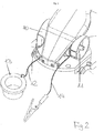
- FIG. 1 illustrated dispensing valve basically has a hose connection 1, fork-shaped alssp Drssenende inlet areas 2, a valve body 3, an actuating mechanism with a handle 4 and an actuating lever 5 and an outlet pipe 6.
- the outlet pipe 6 is, as in FIG. 3 to recognize, designed as a quick change tube.
- the valve body 3 has two diametrically opposite, formed as a swivel joint liquid passages at which takes place from the inlet regions 2, an inflow of liquid into the valve body 3.
- the inlet regions 2 are formed pivotable relative to the valve body 3 around these pivot joints 7.
- a connecting web 8 (designed as a liquid-permeable connecting tube) is arranged in the vicinity of the valve body 3 in order to increase the stability of the dispensing valve.
- a sight glass indicated at 9 is arranged, through which the refueling process can be monitored.
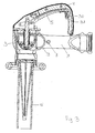
- FIG. 2 shows details of the automatic return according to the invention.
- two take-up reels 10, 11 are arranged, which are biased by means not shown springs in the winding position.
- a cord 12 with a protective cap 13 attached thereto for the outlet pipe 6 can be deducted.
- the protective cap 13 can protect the outlet end of the outlet pipe 6. If the protective cap 13 is removed in preparation for the refueling process, the cord 12 is wound onto the spool 10 and the protective cap 13 is pulled against the dispensing valve. It does not hang down and does not interfere with handling during the refueling process.
- a ground wire 14 is wound, to which a ground terminal is connected. Again, in the idle state, the ground wire 14 is wound up and the ground terminal does not hang loose. Before start the refueling operation, a required length of the grounding cable 14 is pulled out and a ground connection is established between the nozzle and, for example, the aircraft.
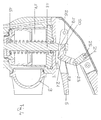
- the main valve of the dispensing valve according to the invention has, within the valve body 3, a valve disk which, in the closed state, seals against a valve seat 16 with a valve seal 15. In this closed position, the valve is held by a valve spring 17. By means of a valve rod 18, the valve can be moved against the force of the spring 17 in an open position.
- the valve rod 18 has in the direction away from the valve seat 16 end a transverse to its axis bore 19 through which engages the actuating end 20 of a 21 pivotally connected to the actuating lever 5 driving lever 22.
- the driving lever 22 is pivotally connected at 23 with a lever 24, the second end is in turn pivotally connected at 25 to a fixed part of the valve body and the handle.
- FIG. 4 shows the nozzle in the closed state.
- the valve seal 15 is liquid-tight against the valve seat 16. If you move the operating lever 5 from the in FIG. 4 shown rest position, describes the pivot axis 21 of the driving lever 22 a circular arc whose radius is the distance between the axis 26 of the actuating lever 5 and said pivot axis 21 corresponds. At the same time, the distance between the axis 21 of the driving lever 22 and the axis 25 of the reversing lever 24 is reduced by the movement of the actuating lever 5, so that they experience a rotational movement about the axis 23 relative to one another.
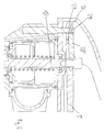
- FIGS. 6 and 7 show a second embodiment of the invention, in which the coupling gear has a drag lever.
- the actuating lever 5 is here via a projection 27 in operative connection with a cam follower 28, which is articulated at 29 pivotally.
- the drag lever 28 is at its end facing away from the pivot axis 29 in An operative connection with a bore in the valve rod 18 and can lift this.
- the actuating lever 5 has a stopping aid 30, which allows in three defined by detents 31 on the handle 4 open positions that the operating lever 5 is kept open with reduced manual force, as in EP 2 186 773 A1 is described.
- the subject matter of this application is also incorporated herein by reference.
Landscapes
- Engineering & Computer Science (AREA)
- Mechanical Engineering (AREA)
- Mechanically-Actuated Valves (AREA)
- Loading And Unloading Of Fuel Tanks Or Ships (AREA)
- Closures For Containers (AREA)
Priority Applications (11)
| Application Number | Priority Date | Filing Date | Title |
|---|---|---|---|
| EP11183398A EP2574595A1 (de) | 2011-09-30 | 2011-09-30 | Zapfventil |
| AU2012227224A AU2012227224B9 (en) | 2011-09-30 | 2012-09-20 | Fuel nozzle |
| NZ602558A NZ602558B (en) | 2011-09-30 | 2012-09-20 | Fuel nozzle |
| CA2790759A CA2790759C (en) | 2011-09-30 | 2012-09-21 | Fuel nozzle |
| DK12186468.0T DK2574596T3 (da) | 2011-09-30 | 2012-09-28 | Påfyldningspistol |
| PL12186468T PL2574596T3 (pl) | 2011-09-30 | 2012-09-28 | Zawór dozujący |
| ES12186468T ES2530371T3 (es) | 2011-09-30 | 2012-09-28 | Válvula dispensadora |
| US13/630,737 US9266710B2 (en) | 2011-09-30 | 2012-09-28 | Fuel nozzle |
| PT121864680T PT2574596E (pt) | 2011-09-30 | 2012-09-28 | Válvula de distribuição |
| EP12186468.0A EP2574596B1 (de) | 2011-09-30 | 2012-09-28 | Zapfventil |
| CN201210370757.0A CN103030090B (zh) | 2011-09-30 | 2012-09-29 | 分配阀 |
Applications Claiming Priority (1)
| Application Number | Priority Date | Filing Date | Title |
|---|---|---|---|
| EP11183398A EP2574595A1 (de) | 2011-09-30 | 2011-09-30 | Zapfventil |
Publications (1)
| Publication Number | Publication Date |
|---|---|
| EP2574595A1 true EP2574595A1 (de) | 2013-04-03 |
Family
ID=46888337
Family Applications (2)
| Application Number | Title | Priority Date | Filing Date |
|---|---|---|---|
| EP11183398A Withdrawn EP2574595A1 (de) | 2011-09-30 | 2011-09-30 | Zapfventil |
| EP12186468.0A Active EP2574596B1 (de) | 2011-09-30 | 2012-09-28 | Zapfventil |
Family Applications After (1)
| Application Number | Title | Priority Date | Filing Date |
|---|---|---|---|
| EP12186468.0A Active EP2574596B1 (de) | 2011-09-30 | 2012-09-28 | Zapfventil |
Country Status (9)
| Country | Link |
|---|---|
| US (1) | US9266710B2 (da) |
| EP (2) | EP2574595A1 (da) |
| CN (1) | CN103030090B (da) |
| AU (1) | AU2012227224B9 (da) |
| CA (1) | CA2790759C (da) |
| DK (1) | DK2574596T3 (da) |
| ES (1) | ES2530371T3 (da) |
| PL (1) | PL2574596T3 (da) |
| PT (1) | PT2574596E (da) |
Families Citing this family (9)
| Publication number | Priority date | Publication date | Assignee | Title |
|---|---|---|---|---|
| US9051164B2 (en) * | 2011-09-30 | 2015-06-09 | Elaflex Hiby Tanktechnik Gmbh & Co. Kg | Dispensing valve |
| US9938022B2 (en) | 2014-06-10 | 2018-04-10 | Gammon Technical Products, Inc. | Fueling nozzle adapter |
| US11097940B2 (en) | 2016-10-25 | 2021-08-24 | Ford Motor Company | Methods and apparatus to ensure grounding between vehicles during vehicle-to-vehicle refueling operations |
| WO2018080449A1 (en) | 2016-10-25 | 2018-05-03 | Ford Motor Company | Methods and apparatus to ensure grounding between vehicles during vehicle-to-vehicle refueling operations |
| CN106698321A (zh) * | 2016-12-22 | 2017-05-24 | 山东健康源生物工程有限公司 | 一种便捷式防漏油倒油器 |
| US10737928B2 (en) | 2018-02-23 | 2020-08-11 | Husky Corporation | Nozzle for delivery of auxiliary or additive fluid for treating exhaust for a diesel motor for autos or truck vehicle or the like |
| USD946709S1 (en) * | 2020-05-08 | 2022-03-22 | Lutz Pumpen Gmbh | Dispenser gun |
| USD1105351S1 (en) * | 2023-01-06 | 2025-12-09 | Dukshin Corp., Ltd. | Nozzle for fluid pump |
| US20250333290A1 (en) * | 2024-04-29 | 2025-10-30 | Tilford Loy | Gasoline Transfer System |
Citations (4)
| Publication number | Priority date | Publication date | Assignee | Title |
|---|---|---|---|---|
| GB1562494A (en) * | 1975-09-12 | 1980-03-12 | Emco Wheaton | Nozzles |
| US5159523A (en) * | 1990-10-24 | 1992-10-27 | Cornerstone Fuels, Inc. | Grounding system and detection circuit for fueling |
| WO2003045831A1 (en) * | 2001-11-30 | 2003-06-05 | Honeywell Specialty Chemicals Seelze Gmbh | Container discharge system with grounding device |
| EP2186773A1 (de) | 2008-11-17 | 2010-05-19 | ELAFLEX - Gummi Ehlers GmbH | Zapfventil mit handbetätigtem Schalthebel und Aufhaltehilfe |
Family Cites Families (15)
| Publication number | Priority date | Publication date | Assignee | Title |
|---|---|---|---|---|
| US1929719A (en) * | 1928-01-11 | 1933-10-10 | Edmund Rogers | Liquid metering and dispensing apparatus |
| US2826455A (en) * | 1956-07-10 | 1958-03-11 | Edward B Furton | Dustproof cap for fluid dispensing nozzles |
| GB887089A (en) * | 1958-08-30 | 1962-01-17 | Ad Struver G M B H | Improvements in or relating to devices for filling liquid fuel tanks |
| US3255771A (en) * | 1963-11-22 | 1966-06-14 | Continental Oil Co | Air fueling system |
| US3759423A (en) * | 1971-05-18 | 1973-09-18 | Sun Oil Co Pennsylvania | Contamination-preventing nozzle |
| US3815784A (en) * | 1972-08-14 | 1974-06-11 | Sun Oil Co Pennsylvania | Dispensing nozzle arrangement providing electrical lockout |
| US4930666A (en) * | 1988-10-28 | 1990-06-05 | The Coca-Cola Company | Juice dispensing system for a refrigerator door |
| JPH09169399A (ja) * | 1995-12-20 | 1997-06-30 | Tokico Ltd | 給液ノズル |
| GB2369447B (en) * | 2000-07-29 | 2004-06-23 | Newson Gale Ltd | Electrical resistance monitoring device |
| US7078621B1 (en) * | 2001-01-25 | 2006-07-18 | Lightning Eliminators & Consultants, Inc. | Grounding system for floating roofs in flammable storage tanks |
| US6659306B2 (en) * | 2001-10-02 | 2003-12-09 | Badger Meter, Inc. | Electronic lube gun with master station control |
| DE102004039961A1 (de) * | 2004-08-18 | 2006-03-09 | Protechna S.A. | Verfahren zur Herstellung einer als Kunststoff-Spritzgußteil gefertigten Entnahmearmatur für Transport- und Lagerbehälter aus Kunststoff oder Metall für Flüssigkeiten |
| GB2449285B (en) * | 2007-05-17 | 2010-08-11 | Newson Gale Ltd | Improvements relating to the testing of an earth connection |
| PL2354626T3 (pl) * | 2010-01-29 | 2013-12-31 | Elaflex Hiby Tanktechnik Gmbh & Co | Zespół zaworu dozującego złożony z podstawowego zaworu dozującego i nasadki elementu złącznego i system modułowy złożony z podstawowego zaworu dozującego i wielu nasadek elementu złącznego |
| US9051164B2 (en) * | 2011-09-30 | 2015-06-09 | Elaflex Hiby Tanktechnik Gmbh & Co. Kg | Dispensing valve |
-
2011
- 2011-09-30 EP EP11183398A patent/EP2574595A1/de not_active Withdrawn
-
2012
- 2012-09-20 AU AU2012227224A patent/AU2012227224B9/en not_active Ceased
- 2012-09-21 CA CA2790759A patent/CA2790759C/en active Active
- 2012-09-28 ES ES12186468T patent/ES2530371T3/es active Active
- 2012-09-28 US US13/630,737 patent/US9266710B2/en active Active
- 2012-09-28 PT PT121864680T patent/PT2574596E/pt unknown
- 2012-09-28 DK DK12186468.0T patent/DK2574596T3/da active
- 2012-09-28 PL PL12186468T patent/PL2574596T3/pl unknown
- 2012-09-28 EP EP12186468.0A patent/EP2574596B1/de active Active
- 2012-09-29 CN CN201210370757.0A patent/CN103030090B/zh active Active
Patent Citations (4)
| Publication number | Priority date | Publication date | Assignee | Title |
|---|---|---|---|---|
| GB1562494A (en) * | 1975-09-12 | 1980-03-12 | Emco Wheaton | Nozzles |
| US5159523A (en) * | 1990-10-24 | 1992-10-27 | Cornerstone Fuels, Inc. | Grounding system and detection circuit for fueling |
| WO2003045831A1 (en) * | 2001-11-30 | 2003-06-05 | Honeywell Specialty Chemicals Seelze Gmbh | Container discharge system with grounding device |
| EP2186773A1 (de) | 2008-11-17 | 2010-05-19 | ELAFLEX - Gummi Ehlers GmbH | Zapfventil mit handbetätigtem Schalthebel und Aufhaltehilfe |
Also Published As
| Publication number | Publication date |
|---|---|
| CA2790759A1 (en) | 2013-03-30 |
| EP2574596A1 (de) | 2013-04-03 |
| AU2012227224A1 (en) | 2013-04-18 |
| US9266710B2 (en) | 2016-02-23 |
| AU2012227224B9 (en) | 2015-01-15 |
| US20130081738A1 (en) | 2013-04-04 |
| AU2012227224B2 (en) | 2014-12-18 |
| CN103030090A (zh) | 2013-04-10 |
| CN103030090B (zh) | 2018-01-30 |
| DK2574596T3 (da) | 2015-02-02 |
| ES2530371T3 (es) | 2015-03-02 |
| PT2574596E (pt) | 2015-02-17 |
| CA2790759C (en) | 2018-10-23 |
| EP2574596B1 (de) | 2014-11-12 |
| NZ602558A (en) | 2014-03-28 |
| PL2574596T3 (pl) | 2015-04-30 |
Similar Documents
| Publication | Publication Date | Title |
|---|---|---|
| EP2574596B1 (de) | Zapfventil | |
| EP2684619B1 (de) | Hochdruckreiniger mit einem integrierten Textilflachschlauch | |
| EP2603392B1 (de) | Deckelloser einfüllstutzen | |
| EP3765205B1 (de) | Abgabeeinrichtung und spender | |
| EP2574597B1 (de) | Zapfventil | |
| EP3999769B1 (de) | Zapfventil für gasförmigen oder verflüssigten kraftstoff mit verzögerung zwischen kupplung und aktivierung | |
| DE1500176A1 (de) | Absperrorgan mit schwenkbarem Sperrglied,insbesondere fuer Wasserleitungssysteme | |
| DE102008057806A1 (de) | Rundmagazin für eine Spulstelle eines Kreuzspulautomaten | |
| EP3203893B1 (de) | Dampfreinigungsgerät-bodendüse und dampfreinigungsgerät | |
| DE19709415A1 (de) | Verschluß für einen Einfüllstutzen eines Kraftfahrzeugtankes | |
| DE19812384A1 (de) | Kraftstoffbehälterverschluß | |
| DE3038339C2 (de) | Vorrichtung zum Füllen von Behältern, insbesondere von Güllefässern | |
| DE69300314T2 (de) | Druckprobepumpe. | |
| EP0694499B1 (de) | Schlauchrückholvorrichtung für Kraftstoffzapfsäulen | |
| EP0067279B1 (de) | Schwenkbares Saugrohr zur Aufnahme eines Fadens von einer Spule | |
| DE3718425C2 (de) | Pumpe, insbesondere Faßpumpe | |
| DE3124132C2 (de) | Vorrichtung zur Zuflußsteuerung | |
| DE29511403U1 (de) | Ventilpistole für ein Hochdruckreinigungsgerät | |
| DE19630347C2 (de) | Faßpumpe | |
| DE2651081A1 (de) | Beregnungsanlage | |
| CH659056A5 (de) | Vorrichtung zum ansaugen und festhalten eines fadens. | |
| DE19607146A1 (de) | Bremsanordnung für eine in einem Gehäuse eingebaute selbstaufwickelnde Kabeltrommel | |
| DE531930C (de) | Schlauchhaspel fuer den Zapfschlauch von Zapfsaeulen | |
| DE10037318C2 (de) | Mechanismus zur Betätigung eines in einer Flugzeug-Abwasser-Ablassvorrichtung angeordneten Ausgleichventils | |
| DE102010005523B4 (de) | Reinigungsgerät |
Legal Events
| Date | Code | Title | Description |
|---|---|---|---|
| PUAI | Public reference made under article 153(3) epc to a published international application that has entered the european phase |
Free format text: ORIGINAL CODE: 0009012 |
|
| AK | Designated contracting states |
Kind code of ref document: A1 Designated state(s): AL AT BE BG CH CY CZ DE DK EE ES FI FR GB GR HR HU IE IS IT LI LT LU LV MC MK MT NL NO PL PT RO RS SE SI SK SM TR |
|
| AX | Request for extension of the european patent |
Extension state: BA ME |
|
| STAA | Information on the status of an ep patent application or granted ep patent |
Free format text: STATUS: THE APPLICATION IS DEEMED TO BE WITHDRAWN |
|
| 18D | Application deemed to be withdrawn |
Effective date: 20131005 |