EP2574702A2 - Dach- oder Wandkonstruktion - Google Patents
Dach- oder Wandkonstruktion Download PDFInfo
- Publication number
- EP2574702A2 EP2574702A2 EP12185516A EP12185516A EP2574702A2 EP 2574702 A2 EP2574702 A2 EP 2574702A2 EP 12185516 A EP12185516 A EP 12185516A EP 12185516 A EP12185516 A EP 12185516A EP 2574702 A2 EP2574702 A2 EP 2574702A2
- Authority
- EP
- European Patent Office
- Prior art keywords
- roof
- strut
- holder
- wall construction
- main
- Prior art date
- Legal status (The legal status is an assumption and is not a legal conclusion. Google has not performed a legal analysis and makes no representation as to the accuracy of the status listed.)
- Granted
Links
Images


Classifications
-
- E—FIXED CONSTRUCTIONS
- E04—BUILDING
- E04B—GENERAL BUILDING CONSTRUCTIONS; WALLS, e.g. PARTITIONS; ROOFS; FLOORS; CEILINGS; INSULATION OR OTHER PROTECTION OF BUILDINGS
- E04B7/00—Roofs; Roof construction with regard to insulation
- E04B7/02—Roofs; Roof construction with regard to insulation with plane sloping surfaces, e.g. saddle roofs
- E04B7/022—Roofs; Roof construction with regard to insulation with plane sloping surfaces, e.g. saddle roofs consisting of a plurality of parallel similar trusses or portal frames
- E04B7/024—Roofs; Roof construction with regard to insulation with plane sloping surfaces, e.g. saddle roofs consisting of a plurality of parallel similar trusses or portal frames the trusses or frames supporting load-bearing purlins, e.g. braced purlins
-
- E—FIXED CONSTRUCTIONS
- E04—BUILDING
- E04B—GENERAL BUILDING CONSTRUCTIONS; WALLS, e.g. PARTITIONS; ROOFS; FLOORS; CEILINGS; INSULATION OR OTHER PROTECTION OF BUILDINGS
- E04B1/00—Constructions in general; Structures which are not restricted either to walls, e.g. partitions, or floors or ceilings or roofs
- E04B1/18—Structures comprising elongated load-supporting parts, e.g. columns, girders, skeletons
- E04B1/24—Structures comprising elongated load-supporting parts, e.g. columns, girders, skeletons the supporting parts consisting of metal
- E04B1/2403—Connection details of the elongated load-supporting parts
- E04B2001/2451—Connections between closed section profiles
-
- E—FIXED CONSTRUCTIONS
- E04—BUILDING
- E04B—GENERAL BUILDING CONSTRUCTIONS; WALLS, e.g. PARTITIONS; ROOFS; FLOORS; CEILINGS; INSULATION OR OTHER PROTECTION OF BUILDINGS
- E04B1/00—Constructions in general; Structures which are not restricted either to walls, e.g. partitions, or floors or ceilings or roofs
- E04B1/18—Structures comprising elongated load-supporting parts, e.g. columns, girders, skeletons
- E04B1/24—Structures comprising elongated load-supporting parts, e.g. columns, girders, skeletons the supporting parts consisting of metal
- E04B1/2403—Connection details of the elongated load-supporting parts
- E04B2001/2457—Beam to beam connections
-
- E—FIXED CONSTRUCTIONS
- E04—BUILDING
- E04B—GENERAL BUILDING CONSTRUCTIONS; WALLS, e.g. PARTITIONS; ROOFS; FLOORS; CEILINGS; INSULATION OR OTHER PROTECTION OF BUILDINGS
- E04B1/00—Constructions in general; Structures which are not restricted either to walls, e.g. partitions, or floors or ceilings or roofs
- E04B1/18—Structures comprising elongated load-supporting parts, e.g. columns, girders, skeletons
- E04B1/24—Structures comprising elongated load-supporting parts, e.g. columns, girders, skeletons the supporting parts consisting of metal
- E04B2001/2466—Details of the elongated load-supporting parts
-
- E—FIXED CONSTRUCTIONS
- E04—BUILDING
- E04B—GENERAL BUILDING CONSTRUCTIONS; WALLS, e.g. PARTITIONS; ROOFS; FLOORS; CEILINGS; INSULATION OR OTHER PROTECTION OF BUILDINGS
- E04B1/00—Constructions in general; Structures which are not restricted either to walls, e.g. partitions, or floors or ceilings or roofs
- E04B1/18—Structures comprising elongated load-supporting parts, e.g. columns, girders, skeletons
- E04B1/24—Structures comprising elongated load-supporting parts, e.g. columns, girders, skeletons the supporting parts consisting of metal
- E04B2001/2487—Portico type structures
-
- E—FIXED CONSTRUCTIONS
- E04—BUILDING
- E04C—STRUCTURAL ELEMENTS; BUILDING MATERIALS
- E04C3/00—Structural elongated elements designed for load-supporting
- E04C3/02—Joists; Girders, trusses, or trusslike structures, e.g. prefabricated; Lintels; Transoms; Braces
- E04C3/04—Joists; Girders, trusses, or trusslike structures, e.g. prefabricated; Lintels; Transoms; Braces of metal
- E04C2003/0404—Joists; Girders, trusses, or trusslike structures, e.g. prefabricated; Lintels; Transoms; Braces of metal beams, girders, or joists characterised by cross-sectional aspects
- E04C2003/0426—Joists; Girders, trusses, or trusslike structures, e.g. prefabricated; Lintels; Transoms; Braces of metal beams, girders, or joists characterised by cross-sectional aspects characterised by material distribution in cross section
- E04C2003/0439—Joists; Girders, trusses, or trusslike structures, e.g. prefabricated; Lintels; Transoms; Braces of metal beams, girders, or joists characterised by cross-sectional aspects characterised by material distribution in cross section the cross-section comprising open parts and hollow parts
-
- E—FIXED CONSTRUCTIONS
- E04—BUILDING
- E04C—STRUCTURAL ELEMENTS; BUILDING MATERIALS
- E04C3/00—Structural elongated elements designed for load-supporting
- E04C3/02—Joists; Girders, trusses, or trusslike structures, e.g. prefabricated; Lintels; Transoms; Braces
- E04C3/04—Joists; Girders, trusses, or trusslike structures, e.g. prefabricated; Lintels; Transoms; Braces of metal
- E04C2003/0404—Joists; Girders, trusses, or trusslike structures, e.g. prefabricated; Lintels; Transoms; Braces of metal beams, girders, or joists characterised by cross-sectional aspects
- E04C2003/0443—Joists; Girders, trusses, or trusslike structures, e.g. prefabricated; Lintels; Transoms; Braces of metal beams, girders, or joists characterised by cross-sectional aspects characterised by substantial shape of the cross-section
- E04C2003/0465—Joists; Girders, trusses, or trusslike structures, e.g. prefabricated; Lintels; Transoms; Braces of metal beams, girders, or joists characterised by cross-sectional aspects characterised by substantial shape of the cross-section square- or rectangular-shaped
-
- E—FIXED CONSTRUCTIONS
- E04—BUILDING
- E04H—BUILDINGS OR LIKE STRUCTURES FOR PARTICULAR PURPOSES; SWIMMING OR SPLASH BATHS OR POOLS; MASTS; FENCING; TENTS OR CANOPIES, IN GENERAL
- E04H15/00—Tents or canopies, in general
Definitions
- the invention relates to a roof or wall construction, in particular for a reusable hall or a reusable tent.
- a scaffold-like wall or roof construction is used in halls and tents with relatively little effort for event purposes, for storage purposes and industrial purposes use. It gives the building structure and can be used for attaching walls, such as a tarpaulin or a metal skin.
- a generic roof or wall construction has at least one main strut extending in a first extension direction and at least one transverse strut attached at least indirectly to the main strut, which extends in a second extension direction deviating from the first extension direction, preferably enclosing it at a right angle ,
- at least one attachment device for fastening a fastened to the cross member or hereby integrally connected holder is provided on an outer side of the main strut.
- the main struts can form vertical beams, which are connected to each other by means of the then horizontally oriented cross braces.
- the main struts are preferably part of a roof truss usually comprising two main struts, whose two main struts are connected to one another in the region of a roof ridge.
- each other standing main struts and cross struts are firmly connected to each other for the stated purpose. This is currently usually done by means of screw that connect the holder with the main carrier.
- the main strut may have mounting holes, in which screws or bolts are inserted, which also extend through an end-side retaining plate of the holder of the transverse strut.
- Also constructions are known in which welded to the main strut U-shaped mounting bracket are provided, to which the cross braces can be screwed.
- the object of the invention is therefore to provide a generic roof or wall construction available, which allows the attachment of the cross member to the main strut in a simple manner.
- attachment device two extending in the first direction of extension Support webs with mutually facing support surfaces on both sides of a fixing region through which the at least partially arranged in the fixing region holder of the cross strut is fixed in position at least transversely to the first direction of extension of the main strut.
- a fixing area is defined directly on the main strut by means of two support surfaces extending in the first extension direction and thus parallel to one another, which are preferably an integral part of the main body of the main strut.
- the holder is arranged, which is limited in movement by this arrangement in view of its relative movement relative to the main strut, at least in a direction orthogonal to both directions of extension.
- That portion of the holder which is arranged in the fixing area bounded by the support surfaces preferably has external dimensions which limit the relative mobility of the holder relative to the main bar orthogonal to the two extension directions, preferably to a maximum of 10 mm.
- the opposite support surface facing each other but need not be completely aligned parallel to each other.
- the said support surfaces do not yet create a complete connection between the holder and the main strut. However, along with other measures described below, they provide a very simple and complete connection method that is flexible and inexpensive. However, provided on the main strut and by the support surface bounding fixing area may also be useful if in a conventional manner, the connection between the main struts and the holders by means of screws or the like. In such a case, the fixing areas are a valuable assembly aid since they facilitate the positioning of the holders.
- the roof or wall construction not only each have a main strut and cross member, but each has a plurality at least partially mutually parallel main struts and a plurality of parallel cross struts, the cross struts connecting two main struts together.
- the main struts can be full profiles.
- hollow profiles made of metal, in particular of steel or aluminum, are preferred. These can be produced in a simple manner in continuous profile production processes, such as, for example, by continuous casting, wherein the support webs with the support bearing surfaces can also be an immediate part of such a hollow profile.
- At least one of the support webs is attached to the outside of the main strut in alignment with an intermediate wall provided within the hollow profile.
- This intermediate wall separates the inner region of the hollow profile into at least two partial chambers. Because this intermediate wall is arranged within the hollow profile where a support surface is located on the outside of the hollow profile, the forces introduced here from the outside into the main strut can be supported in a particularly advantageous manner while avoiding unwanted strong deformation of the main strut.
- Under the said alignment is understood in the context of the invention that the support web and the inner wall are offset from one another by not more than 5 mm.
- the support webs has a piping groove for receiving a welt.
- the support bridge in question thus fulfills a dual function. To the he limited in the manner described, the mobility of the holder of the crossbar. On the other hand, the carrier of the Kedernut, which is thus arranged outside of the hollow profile. In hollow profiles typically used in the case of generic roof or wall constructions with walls which define a rectangular cross section, the piping groove is thus provided outside this cross section.
- the aforementioned shape with the fixing area which is limited by support surfaces on both sides, as mentioned above, taken alone does not lead to a complete fixing of the holder on the main carrier.
- the shaping may be in the manner explained below, wherein other possibilities are also encompassed by the invention.
- At least one of the support surfaces is provided at the bottom of a retaining surface bounded on both sides by retaining surfaces into which the holder is at least partially inserted and which thereby counteracts a separation of the holder from the main strut in the direction of the second extension direction.
- an undercut is caused by the said retaining groove, which counteracts a separation of the transverse strut from the main strut at least until the holder has been pulled out of the retaining groove. Due to the opposite second support surface, however, this is not possible without tilting the main strut and the crossbar against each other.
- a retaining groove in the region of both support surfaces.
- it is preferably the top of the two support surfaces in the erected state of the roof or wall construction, so that after inserting the holder into the groove, the main strut and the cross member can already be handled together the weight of the crossbar together with the second support surface counteracts an escape of the holder from the holding groove.
- it can also be advantageous configurations with two-sided holding, in which a displacement of the holder relative to the main strut after assembly only in the direction of extension of the main strut is possible.
- the retaining groove is preferably formed by walls which are an integral part of a main body of the main strut, in particular a one-piece part of a hollow profile. It is therefore preferably walls, which are already provided in the production of the profile and which extend over the entire length of the profile in the extension direction.
- a very simple design of the retaining groove provides that on the outer side of the main strut, for example, an L-shaped profile section is provided which, together with an outer side of the main strut in Fixing area forms the said retaining groove.
- an outer side of a wall of the above-described piping groove forms one of the side surfaces of the retaining groove.
- the trained as an open hollow profile wall of the Kedernut is such part of the side bar that it projects beyond the fixing area and thus forms the closed on three sides holding groove.
- the walls of the Kedernut thus assume a dual function. Also, this provides the advantage that the piping groove is still easily accessible even with already mounted cross braces, since the holder does not affect the access to Kedernut.
- any relative mobility of the main strut and the transverse strut orthogonal to the first direction of extent is prevented.
- a related positive coupling between the main strut and the cross member is considered advantageous, preferably a coupling, which is produced by said tilting movement.
- the attachment device and the holder have cooperating positive engagement means by which the mobility of the holder is limited in the direction of the first direction of extent, when the holder is arranged between the support webs.
- the attachment means between the webs recesses or projections which cooperate with projections or depressions on the holder, in particular on a base plate of the holder, in the manner mentioned.
- At least one of the support webs has at least one point of interruption, wherein a securing portion of the holder extends in the mounted position in this point of interruption, so that the mobility of the holder in the direction of the first direction of extent is limited thereby.
- the arrangement of the interruption position defines at the respective support web, where the cross strut can be attached to the main strut.
- An interruption point of the type mentioned is also subsequently very easy to bring into the respective support web, so that in a simple way new mounting positions for the cross member with respect to the main strut can be created. While this often requires the introduction of new holes in the main strut in known systems and this can lead to an unwanted weakening of the main strut, the introduction of new interruption points in the support web is not accompanied by a deterioration of the stability of the main strut.
- Particularly advantageous is the arrangement of the interruption points in a support web, which is provided on the side of the fixing area facing the center of gravity of the cross section. The closer the weakening is to the center of gravity of the profile, the lower the weakening effect.
- the holder has a base plate, which is arranged in the fixing area and aligned parallel to the outside of the main strut.
- This base plate is in terms of their dimensions adapted to the distance of the support surfaces to each other. Their thickness is preferably adapted to the width of the retaining groove.
- the retaining groove is preferably slightly wider compared to the thickness of the base plate.
- the holder may be integrally connected to the transverse strut, for example welded thereto.
- the separability of the holder of the crossbar is in terms of assembly / disassembly of advantage. It makes it possible to first bring the holder with said pivoting movement into its desired position relative to the main strut in order to connect it to the cross strut only subsequently. This is a considerable advantage during assembly, since otherwise the required pivoting movement would be required in the case of two main struts, which are connected by a cross strut respectively by means of a holder, after attachment of the cross member by means of the first holder on the first main strut the Make connection with the second holder in that the main struts are pivoted against each other.
- main strut attachment means for attaching two pointing in opposite directions cross struts are provided. In this way, a plurality of main struts can be interconnected by mutually aligned transverse struts.
- a main strut with a total of four attachment means is provided, which are preferably arranged mirror-symmetrically relative to the cross section of the main strut to two axes.
- the cross strut may be advantageous to connect the cross strut with the main strut additionally via a support strut. This creates on said holder over another connection between the crossbar and main strut.
- the support strut is connected by means of the further attachment means with the main strut.
- On the opposite side of the support strut is preferably connected by one of said bolts or one of said screws with the crossbar.
- the main strut is preferably a part of a roof truss of the roof structure, while the cross strut forms a purlin of the roof structure.
- this preferably has two main struts, each forming vertically aligned support, which are interconnected by the transverse strut, which in turn is horizontally aligned.
- FIG. 1 shows a construction according to the invention of a hall or tent building. This has a roof construction 10 and wall constructions 8.
- the roof construction 10 has roof trusses 16 as main components, which comprise two main struts 20 each extending from the eaves 12 to the ridge 14 and which are connected to each other via a plurality of roof purlins 50.
- the wall constructions 8 are otherwise constructed in the same way as the roof construction 10 with a modified arrangement and alignment with vertical supports 8a and connecting transverse struts 8b. All further embodiments therefore relate equally to a roof construction 10 as well as the wall constructions 8.
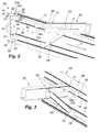
- FIG. 2 and 4 illustrate the attachment of the transverse struts forming roof purlins 50 on the main struts 20th
- the main struts 20 are formed as hollow profiles. They have an approximately rectangular main portion 22 which comprises a total of five hollow chambers 26 separated from one another by intermediate walls 24. At the upper and at the lower end of the main portion 22 each outwardly facing support webs 28 are provided, at the end remote from the main portion 22 slotted hollow sections 30 are provided which each surround a Kedernut 32. Between the provided at the upper end and at the lower end of the main portion 22 supporting webs 28 each have two further support webs 34 are arranged. These aligned to an intermediate wall 24 of the main portion 22 extending support webs 34 define together with the respective outer Support webs 28 fixing areas 36, which serve indirectly the attachment of the Dachpfetten 50.
- holder 70 This is done primarily by means of in the Fig. 4 separately shown holder 70.
- These holders 70 have a base plate 72, from which parallel to each other two fastening extensions 74 extend outward, between which the respective Dachpfette 50 can be fastened.
- the base plates 72 are each arranged in the fixing area 36.
- the mobility of the base plate 72 in the fixing region 36 is limited by supporting surfaces 28a, 34a pointing in the direction of the fixing region 36 on the support webs 28, 34. Furthermore, the base plate 72 extends into a retaining groove 38, at the bottom of the support surface 28a is provided. The side surfaces of this groove 28 are formed by an outer side 22a of the main body 22 and an outer side 30a of the slotted Keder hollow profile 30 partially overlapping the fixing region 36. Due to the arrangement of the base plate 72 within the retaining groove 38, the holder 70 can not be separated from the main strut 20 without tilting in the direction of extension 4 of the roof purlins 50.
- a retainer 70 inserted into the strut 20 remains securely in position during the assembly process.
- break points 34 b are provided in the support web.
- the base plate 72 has projections 72a which extend into these interruption points 34b. In the in the FIGS. 2 and 3 shown position, the holder 70 is therefore held form-fitting by a shift in the direction of extension 2.
- the connection between the holder 70 and the Dachpfette 50 is realized by two screws or bolts 68 which project through holes 74a in the extensions 74 and by corresponding holes in the Dachpfette 50.
- the base plate 72 facing away from the bolt 68 also serves in FIG. 3 apparent manner, the attachment of an optional support strut 90, which at its end facing away from the bolt 68 also has a base plate 92 which is used in a similar manner as the base plate 72 of the holder 70 in a Festlegungs Scheme 36 of the main strut 20.
- FIG. 5 illustrates again the arrangement of the holder 70 and in particular of its base plate 72 in the Festlegungs Scheme 36 of the strut 20. Here it is well seen that the upper end of the base plate 72 is received in the retaining groove 38.
- FIG. 5 is also illustrated by dashed lines, as the holder 70 is inserted into the Festlegungs Symposium 36. For this purpose, it is attached angled in the manner outlined, in order subsequently to be inserted deeper into the retaining groove 38 while the pivoting movement is simultaneous. During this pivoting movement, the positive coupling of the holder 70 with the main strut 20 in the region of the interruption points 34b and the extensions 72a takes place.
- the described type of connection between the holder 70 and the main strut 20 is very easy to implement. However, it is also very stable when two mutually facing holder 70 are connected to adjacent main struts 20 together by a Dachpfette 50. Since the connecting roof purlin 50 any tilting movement of the holder 70 in the sense of FIG.
- roof purlins 50 may then also serve for attaching other components, such as a metal skin for the hall. In the present case, however, it is advantageous if in the also in FIG. 5 illustrated by dotted lines manner a tarpaulin 40 with marginal piping 42 is used.
Landscapes
- Engineering & Computer Science (AREA)
- Architecture (AREA)
- Physics & Mathematics (AREA)
- Electromagnetism (AREA)
- Civil Engineering (AREA)
- Structural Engineering (AREA)
- Tents Or Canopies (AREA)
Abstract
Description
- Die Erfindung betrifft eine Dach- oder Wandkonstruktion, insbesondere für eine wiederverwendbare Halle oder ein wiederverwendbares Zelt. Eine solche gerüstartige Wand- oder Dachkonstruktion findet bei mit vergleichsweise wenig Aufwand aufbaubaren Hallen und Zelten für Veranstaltungszwecke, für Lagerzwecke und industrielle Zwecke Verwendung. Sie gibt dem Gebäude Struktur und kann zur Anbringung von Wandungen, beispielsweise einer Zeltplane oder einer Blechhaut dienen. Eine gattungsgemäße Dach- oder Wandkonstruktion weist dabei mindestens eine sich in einer ersten Erstreckungsrichtung erstreckende Hauptstrebe und mindestens eine zumindest mittelbar an der Hauptstrebe befestigte Querstrebe auf, welche sich in einer von der ersten Erstreckungsrichtung abweichenden, vorzugsweise mit dieser einen rechten Winkel einschließenden, zweiten Erstreckungsrichtung erstreckt. Dabei ist an einer Außenseite der Hauptstrebe mindestens eine Anbringungseinrichtung zur Befestigung eines an der Querstrebe befestigten oder hiermit einstückig verbundenen Halters vorgesehen.
- Gattungsgemäße Dach- oder Wandkonstruktionen sind im angegebenen Bereich allgemein bekannt. Als Wandkonstruktion können die Hauptstreben vertikale Träger bilden, welche mittels der dann horizontal ausgerichteten Querstreben miteinander verbunden sind. Im Falle einer Dachkonstruktion sind die Hauptstreben vorzugsweise Teil eines üblicherweise zwei Hauptstreben umfassenden Dachbinders, dessen beide Hauptstreben im Bereich eines Dachfirstes miteinander verbunden sind.
- Die üblicherweise in rechtem Winkel zueinander stehenden Hauptstreben und Querstreben sind für den angegebenen Zweck fest miteinander zu verbinden. Dies erfolgt derzeit üblicherweise mittels Schraubverbindungen, die den Halter mit dem Hauptträger verbinden. So kann die Hauptstrebe Befestigungsbohrungen aufweisen, in welche Schrauben oder Bolzen eingesteckt werden, die auch durch eine endseitige Halteplatte des Halters der Querstrebe verlaufen. Auch sind Konstruktionen bekannt, bei denen mit der Hauptstrebe verschweißte U-förmige Befestigungsbügel vorgesehen sind, an welchen die Querstreben angeschraubt werden können.
- Die bekannten Techniken zur Verbindung der Hauptstrebe mit der Querstrebe gehen mit einem vergleichsweise hohen Fertigungsaufwand einher und sind hinsichtlich ihrer Flexibilität, die Anordnung der Querstreben an der Hauptstrebe betreffend, wenig vorteilhaft.
- Aufgabe der Erfindung ist es daher, eine gattungsgemäße Dach- oder Wandkonstruktion zur Verfügung zu stellen, die die Anbringung der Querstrebe an der Hauptstrebe in einfacher Weise gestattet.
- Erfindungsgemäß wird dies dadurch erreicht, dass die Anbringungseinrichtung zwei sich in der ersten Erstreckungsrichtung erstreckende Stützstege mit aufeinander zu weisenden Stützflächen beidseitig eines Festlegungsbereichs aufweist, durch die der zumindest partiell im Festlegungsbereich angeordnete Halter der Querstrebe zumindest quer zur ersten Erstreckungsrichtung an der Hauptstrebe lagefixiert ist.
- Es ist somit vorgesehen, dass unmittelbar an der Hauptstrebe durch zwei sich in erster Erstreckungsrichtung und somit zueinander parallel erstreckende Stützflächen, die vorzugsweise einstückiger Teil des Grundkörpers der Hauptstrebe sind, ein Festlegungsbereich definiert wird. Innerhalb dieses Festlegungsbereichs ist der Halter angeordnet, der durch diese Anordnung in Hinblick auf seine Relativbeweglichkeit gegenüber der Hauptstrebe zumindest in einer zu beiden Erstreckungsrichtungen orthogonalen Richtung bewegungslimitiert ist. Jener Abschnitt des Halters, der im durch die Stützflächen begrenzten Festlegungsbereich angeordnet ist, weist vorzugsweise Außenmaße auf, die die Relativbeweglichkeit des Halters gegenüber der Hauptstrebe orthogonal zu den genannten beiden Erstreckungsrichtungen vorzugsweise auf maximal 10 mm limitieren. Die einander gegenüberliegenden Stützfläche weisen aufeinander zu, müssen jedoch nicht vollständig parallel zueinander ausgerichtet sein.
- Die genannten Stützflächen schaffen noch keine vollständige Verbindung zwischen dem Halter und der Hauptstrebe. Zusammen mit weiteren nachfolgend noch beschriebenen Maßnahmen bieten sie jedoch eine sehr einfache und vollständige Verbindungsmethode, die flexibel und unaufwändig ist. Allerdings kann der an der Hauptstrebe vorgesehene und durch die Stützfläche begrenze Festlegungsbereich auch dann sinnvoll sein, wenn in an sich bekannter Weise die Verbindung zwischen den Hauptstreben und den Haltern mittels Schrauben oder dergleichen erfolgt. In einem solchen Falle stellen die Festlegungsbereiche eine wertvolle Montagehilfe dar, da sie die Positionierung der Halter erleichtern.
- Vorzugsweise weist die Dach- oder Wandkonstruktion natürlich nicht nur jeweils eine Hauptstrebe und Querstrebe auf, sondern verfügt jeweils über eine Vielzahl zumindest zum Teil zueinander paralleler Hauptstreben und eine Vielzahl zueinander paralleler Querstreben, wobei die Querstreben jeweils zwei Hauptstreben miteinander verbinden.
- Bei den Hauptstreben kann es sich um Vollprofile handeln. Bevorzugt sind allerdings Hohlprofile aus Metall, insbesondere aus Stahl oder Aluminium. Diese können in einfacher Weise in kontinuierlichen Profilherstellungsverfahren wie beispielsweise durch Strangguss hergestellt werden, wobei auch die Stützstege mit den Stützanlageflächen unmittelbarer Teil eines solchen Hohlprofils sein können.
- Zur Erzielung einer besonders hohen Stabilität im Bereich der Stützstege wird es als besonders vorteilhaft angesehen, wenn mindestens einer der Stützstege an der Außenseite der Hauptstrebe fluchtend zu einer innerhalb des Hohlprofils vorgesehenen Zwischenwandung angebracht ist. Diese Zwischenwandung trennt den Innenbereich des Hohlprofils in mindestens zwei Teilkammern. Dadurch, dass diese Zwischenwandung innerhalb des Hohlprofils dort angeordnet ist, wo sich an der Außenseite des Hohlprofils eine Stützfläche befindet, können die hier von außen in die Hauptstrebe eingeleiteten Kräfte in besonders vorteilhafter Weise und unter Vermeidung einer ungewollten starken Verformung der Hauptstrebe abgestützt werden. Unter dem genannten Fluchten wird im Sinne der Erfindung verstanden, dass der Stützsteg und die Innenwandung gegeneinander um nicht mehr als 5 mm versetzt sind.
- Für Dach- oder Wandkonstruktionen, an denen die Festlegung einer Plane vorgesehen ist, ist es von besonderem Vorteil, wenn mindestens einer der Stützstege eine Kedernut zur Aufnahme eines Keders aufweist. Der betreffende Stützsteg erfüllt somit eine Doppelfunktion. Zum einen limitiert er in der beschriebenen Art und Weise die Beweglichkeit des Halters der Querstrebe. Zum anderen ist der Träger der Kedernut, welche somit außerhalb des Hohlprofils angeordnet ist. Bei üblicherweise im Falle gattungsgemäßer Dach- oder Wandkonstruktionen verwendeter Hohlprofile mit Wandungen, die eine rechteckigen Querschnitt definieren, ist die Kedernut somit außerhalb dieses Querschnitts vorgesehen.
- Die genannten Formgebung mit dem Festlegungsbereich, der beidseitig durch Stützflächen begrenz ist, führt wie oben erwähnt für sich genommen noch nicht zu einer vollständigen Festlegung des Halters am Hauptträger. Zur Vermeidung einer Relativbeweglichkeit in Richtung der ersten und/oder der zweiten Erstreckungsrichtung kann die Formgebung in nachfolgend erläuterter Weise geartet sein, wobei auch andere Möglichkeiten von der Erfindung umfasst sind.
- Besonders bevorzugt ist es, wenn mindestens eine der Stützflächen am Grund einer beidseitig durch Seitenflächen begrenzten Haltenut vorgesehen ist, in die der Halter zumindest partiell eingeschoben ist und die dadurch einer Trennung des Halters von der Hauptstrebe in Richtung der zweiten Erstreckungsrichtung entgegenwirkt. Bei dieser Gestaltung wird durch die genannte Haltenut eine Hinterschneidung bewirkt, die einer Trennung der Querstrebe von der Hauptstrebe zumindest so lange entgegenwirkt, bis der Halter aus der Haltenut herausgezogen wurde. Aufgrund der gegenüberliegenden zweiten Stützfläche ist dies jedoch nicht möglich, ohne die Hauptstrebe und die Querstrebe gegeneinander zu verkippen.
- Grundsätzlich ist es möglich, jeweils eine solche Haltenut im Bereich beider Stützflächen vorzusehen. Im Sinne einer einfacheren Montierbarkeit ist jedoch von Vorteil, wenn zumindest nur eine Seite eine solche Haltenut aufweist, während die gegenüberliegende Seite abschnittsweise oder über die gesamte Länge keine solche Haltenut aufweist. Bei der einen Stützfläche, die eine Haltenut aufweist, handelt es sich vorzugsweise um die im errichteten Zustand der Dach- oder Wandkonstruktion obere der beiden Stützflächen, so dass nach Einschieben des Halters in die Nut die Hauptstrebe und die Querstrebe bereits gemeinsam gehandhabt werden können, da die Gewichtskraft der Querstrebe zusammen mit der zweiten Stützfläche einem Entweichen des Halters aus der Haltenut entgegenwirkt. Es können aber auch Gestaltungen mit beidseitigen Haltenuten vorteilhaft sein, bei denen die eine Verlagerung des Halters gegenüber der Hauptstrebe nach dem Zusammenfügen nur noch in Richtung der Erstreckungsrichtung der Hauptstrebe möglich ist.
- Es sind also Gestaltungen mit durchgehenden Haltenuten im Bereich beider Stützflächen möglich und von der Erfindung umfasst. Demgegenüber von Vorteil sind Gestaltungen, bei denen zumindest die Haltenut auf einer Seite Unterbrechungen aufweist, die das Einschwenken des Halters gestatten. Eine besondere Ausgestaltung dessen sähe vor, dass zumindest auf einer Seite keine durchgehende Haltenut und auch keine unterbrochene Haltenut vorgesehen sind, während auf der Gegenseite eine vorzugsweise durchgehende oder alternativ auch unterbrochene Haltenut vorgesehen ist.
- Die Haltenut wird vorzugsweise durch Wandungen gebildet, die einstückiger Teil eines Grundkörpers der Hauptstrebe, insbesondere einstückiger Teil eines Hohlprofils, sind. Es handelt sich also vorzugsweise um Wandungen, die bereits bei der Herstellung des Profils vorgesehen sind und die sich über die Gesamtlänge des Profils in Erstreckungsrichtung erstrecken.
- Eine sehr einfache Gestaltung der Haltenut sieht vor, dass an der Außenseite der Hauptstrebe ein beispielsweise L-förmiger Profilabschnitt vorgesehen ist, der zusammen mit einer Außenseite der Hauptstrebe im Festlegungsbereich die genannte Haltenut bildet. Besonders von Vorteil ist es jedoch, wenn eine Außenseite einer Wandung der oben beschriebenen Kedernut eine der Seitenflächen der Haltenut bildet. In diesem Fall ist die als offenes Hohlprofil ausgebildete Wandung der Kedernut derart Teil des Seitenstegs, dass sie den Festlegungsbereich überragt und somit die zu drei Seiten hin geschlossene Haltenut bildet. Die Wandungen der Kedernut übernehmen somit eine Doppelfunktion. Auch wird hierdurch der Vorteil erzielt, dass die Kedernut auch bei bereits angebrachten Querstreben noch gut zugänglich ist, da der Halter den Zugang zur Kedernut nicht beeinträchtigt.
- Durch die genannten Stützflächen und die genannte Haltenut ist unter der Annahme, dass es zwischen der Hauptstrebe und der Querstrebe nicht zu einer Kippbewegung kommt, jegliche Relativbeweglichkeit der Hauptstrebe und der Querstrebe orthogonal zur ersten Erstreckungsrichtung unterbunden. Um auch eine Relativbeweglichkeit der Hauptstrebe und der Querstrebe in Richtung der ersten Erstreckungsrichtung zu verhindern, wird eine diesbezügliche formschlüssige Kopplung zwischen der Hauptstrebe und der Querstrebe als vorteilhaft angesehen, vorzugsweise eine Kopplung, die durch die genannte Kippbewegung hergestellt wird.
- Vorzugsweise verfügen somit die Anbringungseinrichtung und der Halter über zusammenwirkende Formschlussmittel, durch die die Beweglichkeit des Halters in Richtung der ersten Erstreckungsrichtung limitiert wird, wenn der Halter zwischen den Stützstegen angeordnet ist. Hierfür könnten beispielsweise an der Anbringungseinrichtung zwischen den Stegen Vertiefungen oder Vorsprünge vorgesehen sein, die mit Vorsprüngen oder Vertiefungen am Halter, insbesondere an einer Basisplatte des Halters, in der genannten Art zusammenwirken. Eine einfache Bohrungen in das Profil im Bereich der Anbringungseinrichtung und einen darein einrückenden Bolzen auf Seiten des Halters führt zu einer technisch einfachen und vorteilhaften Gestaltung.
- Eine baulich sehr einfache weitere Möglichkeit sieht vor, dass mindestens einer der Stützstege mindestens eine Unterbrechungsstelle aufweist, wobei ein Sicherungsabschnitt des Halters sich in montierter Lage in diese Unterbrechungsstelle erstreckt, so dass die Beweglichkeit des Halters in Richtung der ersten Erstreckungsrichtung hierdurch limitiert wird.
- Durch die Unterbrechungsstelle und den hier hineinragenden Sicherungsabschnitt wird in Hinblick auf die erste Erstreckungsrichtung eine formschlüssige Festlegung auf besonders einfache Weise erreicht. Die Anordnung der Unterbrechungsstellung an dem betreffenden Stützsteg definiert, wo die Querstrebe an der Hauptstrebe angebracht werden kann. Eine Unterbrechungsstelle der genannten Art ist auch nachträglich sehr einfach in den betreffenden Stützsteg einzubringen, so dass auf einfache Weise neue Anbringungspositionen für die Querstrebe in Hinblick auf die Hauptstrebe geschaffen werden können. Während dies bei bekannten Systemen häufig das Einbringen neuer Bohrungen in die Hauptstrebe erforderlich macht und diese zu einer ungewünschten Schwächung der Hauptstrebe führen können, geht die Einbringung neuer Unterbrechungsstellen in den Stützsteg nicht mit einer Verschlechterung der Stabilität der Hauptstrebe einher. Besonders vorteilhaft ist die Anordnung der Unterbrechungsstellen in einem Stützsteg, der auf der dem Schwerpunkt des Querschnitts zugewandten Seite des Festlegungsbereichs vorgesehen ist. Je näher die Schwächung dem Schwerpunkt des Profils ist, desto geringer ist die schwächende Wirkung.
- Besonders bevorzugt ist es, wenn der Halter eine Basisplatte aufweist, die im Festlegungsbereich angeordnet und parallel zur Außenseite der Hauptstrebe ausgerichtet ist. Diese Basisplatte ist hinsichtlich ihrer Maße auf den Abstand der Stützflächen zueinander angepasst. Ihr Dicke ist vorzugsweise auf die Breite der Haltenut angepasst. Um die Einfügung der Halteplatte in die Haltenut auf einfache Weise und im Rahmen einer nachfolgend noch beschriebenen Schwenkbewegung zu ermöglichen, ist die Haltenut jedoch vorzugsweise etwas breiter verglichen mit der Dicke der Basisplatte.
- Wie eingangs bereits erwähnt, kann der Halter einstückig mit der Querstrebe verbunden sein, beispielsweise mit dieser verschweißt sein. Bevorzugt wird allerdings eine Gestaltung mit einem von der Querstrebe lösbaren Halter, wobei hierbei insbesondere vorzugsweise der Halter mittels zweier die Relativposition fixierenden Bolzen oder Schrauben mit der Querstrebe verbunden ist.
- Die Trennbarkeit des Halters von der Querstrebe ist in Hinblick auf die Montage/Demontage von Vorteil. Sie ermöglicht es, den Halter zunächst mit der genannten Schwenkbewegung in seine Soll-Position relativ zur Hauptstrebe zu bringen, um ihn erst nachfolgend mit der Querstrebe zu verbinden. Dies stellt bei der Montage einen erheblichen Vorteil dar, da ansonsten die erforderliche Schwenkbewegung es im Falle zweier Hauptstreben, die durch eine Querstrebe jeweils mittels eines Halters verbunden sind, es erforderlich machen würde, nach Anbringung der Querstrebe mittels des ersten Halters an der ersten Hauptstrebe die Verbindung mit dem zweiten Halter dadurch zu realisieren, dass die Hauptstreben gegeneinander verschwenkt werden.
- Bevorzugt ist es, wenn auf zwei einander gegenüberliegenden Seiten der Hauptstrebe Anbringungseinrichtung zur Anbringung zweier in gegenüberliegende Richtung weisende Querstreben vorgesehen sind. Hierdurch kann eine Vielzahl von Hauptstreben durch miteinander fluchtende Querstreben miteinander verbunden werden.
- Auch ist es von Vorteil, wenn auf gleicher Seite der Hauptstrebe versetzt zur genannten Anbringungseinrichtung eine weitere Anbringungseinrichtung der beschriebenen Art vorgesehen ist. In einem solchen Fall sind also zwei zur Aufnahme eines Halters ausgebildete Anbringungseinrichtungen auf der gleichen Seite der Hauptstrebe vorgesehen, wobei diese ggf. auch einen der Stützstege miteinander teilen können.
- Bei einer Gestaltung mit sowohl auf gegenüberliegenden Seiten der Hauptstrebe vorgesehenen Anbringungseinrichtungen als auch jeweils zwei auf beiden gegenüberliegenden Seiten vorgesehenen Anbringungseinrichtungen wird somit eine Hauptstrebe mit insgesamt vier Anbringungseinrichtungen zur Verfügung gestellt, wobei diese vorzugsweise bezogen auf den Querschnitt der Hauptstrebe zu zwei Achsen spiegelsymmetrisch angeordnet sind. Hierdurch wird eine höhere Flexibilität der Einzelteile der Dach- oder Wandkonstruktion hinsichtlich ihrer Ausrichtung und Verwendbarkeit erzielt.
- Bei hoher zu erwartender Belastung der Verbindungsstelle zwischen Querstrebe und Hauptstrebe kann es von Vorteil sein, die Querstrebe mit der Hauptstrebe zusätzlich über eine Stützstrebe zu verbinden. Diese schafft an dem genannten Halter vorbei eine weitere Verbindung zwischen Querstrebe und Hauptstrebe. Im Falle einer Gestaltung der Hauptstrebe mit mehreren Anbringungseinrichtungen auf der gleichen Seite ist es dabei besonders von Vorteil, wenn die Stützstrebe mittels der weiteren Anbringungseinrichtung mit der Hauptstrebe verbunden ist. Auf der gegenüberliegenden Seite ist die Stützstrebe vorzugsweise durch einen der genannten Bolzen oder eine der genannten Schrauben mit der Querstrebe verbunden. Somit kann fallweise die Dach- oder Wandkonstruktion auf einfache Weise durch die Stützstrebe verstärkt werden, welche die gleiche Art von Anbringungseinrichtungen an der Hauptstrebe nutzt wie der Halter der Querstrebe.
- Im Falle einer Dachkonstruktion handelt es sich bei der Hauptstrebe vorzugsweise um einen Teil eines Dachbinders der Dachkonstruktion, während die Querstrebe eine Pfette der Dachkonstruktion bildet. Im Falle einer Wandkonstruktion weist diese vorzugsweise zwei Hauptstreben auf, die jeweils vertikal ausgerichtete Träger bilden, wobei diese durch die Querstrebe, welche ihrerseits horizontal ausgerichtet ist, miteinander verbunden sind.
- Weitere Aspekte und Vorteile der Erfindung ergeben sich aus den Ansprüchen sowie der nachfolgenden Beschreibung eines bevorzugten Ausführungsbeispiels der Erfindung, welches anhand der Figuren erläutert wird. Dabei zeigen:
- Fig. 1
- eine erfindungsgemäße Dachkonstruktion und eine erfindungsgemäße Wandkonstruktion als Teil eines Hallengerüsts in einer Gesamtdarstellung,
- Fig. 2 und Fig. 3
- einen Verbindungsbereich der Dachkonstruktion der
Fig. 1 in zwei unterschiedlichen Perspektiven, - Fig. 4
- einen Halter, der im Verbindungsbereich, welcher in den
Figuren 2 und 3 dargestellt ist, angeordnet ist und der zur Verbindung mit einem Dachbinder und einer Pfette der Dachkonstruktion vorgesehen ist und - Fig. 5
- den Verbindungsbereich der
Figuren 2 und 3 in einer teilweise geschnittenen Darstellung und mit Verdeutlichung der Anbringung des Halters derFigur 4 am Dachbinder. -
Figur 1 zeigt eine erfindungsgemäße Konstruktion eines Hallen- oder Zeltgebäudes. Dieses weist eine Dachkonstruktion 10 und Wandkonstruktionen 8 auf. - Die Dachkonstruktion 10 weist als Hauptbestandteile Dachbinder 16 auf, die zwei jeweils von der Traufe 12 zum First 14 verlaufende Hauptstreben 20 umfassen, und die miteinander jeweils über mehrere Dachpfetten 50 verbunden sind.
- Die Wandkonstruktionen 8 sind bei abgewandelter Anordnung und Ausrichtung mit vertikalen Trägern 8a und verbindenden Querstreben 8b im Übrigen in gleicher Weise wie die Dachkonstruktion 10 aufgebaut. Alle weiteren Ausführungen betreffen daher gleichermaßen eine Dachkonstruktion 10 wie auch die Wandkonstruktionen 8.
- Die
Figur 2 und4 verdeutlichen die Anbringung der Querstreben bildenden Dachpfetten 50 an den Hauptstreben 20. - Wie insbesondere in
Figur 2 gut erkennbar ist, sind die Hauptstreben 20 als Hohlprofile ausgebildet. Sie weisen einen in etwa rechteckigen Hauptabschnitt 22 auf, der insgesamt fünf voneinander durch Zwischenwandungen 24 getrennte Hohlkammern 26 umfasst. Am oberen und am unteren Ende des Hauptabschnitts 22 sind jeweils nach außen weisende Stützstege 28 vorgesehen, an deren dem Hauptabschnitt 22 abgewandten Ende geschlitzte Hohlprofile 30 vorgesehen sind, die jeweils eine Kedernut 32 umgeben. Zwischen den am oberen Ende und am unteren Ende des Hauptabschnitts 22 vorgesehenen Stützstegen 28 sind jeweils zwei weitere Stützstege 34 angeordnet. Diese sich fluchtend zu einer Zwischenwandung 24 des Hauptabschnitts 22 erstreckenden Stützstege 34 begrenzen gemeinsam mit den jeweils außenliegenden Stützstegen 28 Festlegungsbereiche 36, die mittelbar der Anbringung der Dachpfetten 50 dienen. - Dies erfolgt primär mittels in der
Fig. 4 separat dargestellter Halter 70. Diese Halter 70 verfügen über eine Basisplatte 72, von der aus sich parallel zueinander zwei Befestigungsfortsätze 74 nach außen erstrecken, zwischen denen die betreffende Dachpfette 50 befestigbar ist. Wie in denFiguren 2, 3 und5 erkennbar ist, sind die Basisplatten 72 jeweils im Festlegungsbereich 36 angeordnet. - Die Beweglichkeit der Basisplatte 72 im Festlegungsbereich 36 is durch in Richtung des Festlegungsbereichs 36 weisende Stützflächen 28a, 34a an den Stützstegen 28, 34 begrenzt. Weiterhin erstreckt sich die Basisplatte 72 bis in eine Haltenut 38, an deren Grund die Stützfläche 28a vorgesehen ist. Die Seitenflächen dieser Nut 28 werden durch eine Außenseite 22a des Grundkörpers 22 und eine den Festlegungsbereich 36 teilweise überdeckende gegenüberliegende Außenseite 30a des geschlitzten Keder-Hohlprofils 30 gebildet. Durch die Anordnung der Basisplatte 72 innerhalb der Haltenut 38 kann der Halter 70 nicht verkippungsfrei in Erstreckungsrichtung 4 der Dachpfetten 50 von der Hauptstrebe 20 getrennt werden.
- Aufgrund der Gewichtskraft verbleibt ein in die Strebe 20 eingesetzter Halter 70 während des Montageprozesses sicher in seiner Position. Um auch einer Verlagerung des Halters 70 in Richtung der Erstreckungsrichtung 2 der Hauptstrebe 20 entgegenzuwirken, sind im Stützsteg 34 Unterbrechungsstellen 34b vorgesehen. Die Basisplatte 72 verfügt korrespondierend hierzu über Fortsätze 72a, die sich in diese Unterbrechungsstellen 34b erstrecken. In der in den
Figuren 2 und 3 dargestellten Position wird der Halter 70 daher formschlüssig von einer Verschiebung in Richtung der Erstreckungsrichtung 2 abgehalten. - Die Verbindung zwischen dem Halter 70 und der Dachpfette 50 ist über zwei Schrauben oder Bolzen 68 realisiert, welche durch Bohrungen 74a in den Fortsätzen 74 sowie durch korrespondierende Bohrungen in der Dachpfette 50 hindurchragen. Der der Basisplatte 72 abgewandte Bolzen 68 dient darüber hinaus der in
Figur 3 ersichtlichen Weise der Anbringung einer optionalen Stützstrebe 90, welche an ihrem dem Bolzen 68 abgewandten Ende ebenfalls über eine Basisplatte 92 verfügt, welche in ähnlicher Art und Weise wie die Basisplatte 72 des Halters 70 in einem Festlegungsbereich 36 der Hauptstrebe 20 eingesetzt ist. -
Figur 5 verdeutlicht nochmals die Anordnung des Halters 70 und insbesondere von dessen Basisplatte 72 im Festlegungsbereich 36 der Strebe 20. Hier ist gut ersichtlich, dass das obere Ende der Basisplatte 72 in der Haltenut 38 aufgenommen ist. - In
Figur 5 ist mittels gestrichelter Linien auch verdeutlicht, wie der Halter 70 in den Festlegungsbereich 36 eingefügt wird. Er wird hierfür in der skizzierten Weise angewinkelt angesetzt, um anschließend bei gleichzeitiger Schwenkbewegung tiefer in die Haltenut 38 eingeschoben zu werden. Während dieser Schwenkbewegung erfolgt auch die formschlüssige Kopplung des Halters 70 mit der Hauptstrebe 20 im Bereich der Unterbrechungsstellen 34b und der Fortsätze 72a. Die beschriebene Art der Verbindung zwischen dem Halter 70 und der Hauptstrebe 20 ist sehr einfach zu realisieren. Sie ist jedoch auch sehr stabil, sobald zwei aufeinander zu weisende Halter 70 an benachbarten Hauptstreben 20 miteinander durch eine Dachpfette 50 verbunden sind. Da die verbindende Dachpfette 50 jegliche Kippbewegung der Halter 70 im Sinne derFigur 5 verhindert, sind die benachbarten Hauptstreben 20 nach Befestigung der jeweiligen Halter 70 an der verbindenden Dachpfette 50 sicher miteinander verbunden. Die Dachpfetten 50 können dann auch zur Anbringung weiterer Komponenten, wie beispielsweise einer Blechhaut für die Halle dienen. Vorliegend ist es jedoch von Vorteil, wenn in der ebenfalls inFigur 5 mittels gepunkteter Linien verdeutlichten Weise eine Zeltplane 40 mit randseitigen Kedern 42 Verwendung findet.
Claims (15)
- Dach- oder Wandkonstruktion (8, 10), insbesondere für eine wiederverwendbare Halle oder ein wiederverwendbares Zelt mit- mindestens einer sich in einer ersten Erstreckungsrichtung (2) erstreckenden Hauptstrebe (20) und- mindestens einer an der Hauptstrebe (20) befestigten Querstrebe (50), welche sich in einer von der ersten Erstreckungsrichtung (2) abweichenden zweiten Erstreckungsrichtung (4) erstreckt,
wobei an einer Außenseite der Hauptstrebe mindestens eine Anbringungseinrichtung zur Befestigung eines an der Querstrebe (20) befestigten Halters (70) oder eines einstückig mit der Querstrebe verbundenen Halters vorgesehen ist,
dadurch gekennzeichnet, dass
die Anbringungseinrichtung zwei sich in der ersten Erstreckungsrichtung (2) erstreckende Stützstege (28, 34) mit aufeinander zu weisenden Stützflächen (28a, 34a) beidseitig eines Festlegungsbereichs (36) aufweist, durch die der zumindest partiell im Festlegungsbereich (36) angeordnete Halter (70) zumindest quer zur ersten Erstreckungsrichtung (2) an der Hauptstrebe (20) lagefixiert ist. - Dach- oder Wandkonstruktion (10) nach Anspruch 1,
dadurch gekennzeichnet, dass
die Hauptstrebe (20) als Hohlprofil (20) ausgebildet ist. - Dach- oder Wandkonstruktion (10) nach Anspruch 2,
dadurch gekennzeichnet, dass
mindestens einer der Stützstege (34) an der Außenseite der Hauptstrebe (20) fluchtend zu einer innerhalb des Hohlprofils (20) vorgesehenen Zwischenwandung (24) angebracht ist. - Dach- oder Wandkonstruktion (10) nach einem der vorstehenden Ansprüche,
dadurch gekennzeichnet, dass
an einem der Stützstege (28) eine Kedernut (32) zur Aufnahme eines Keders (42) vorgesehen ist. - Dach- oder Wandkonstruktion (10) nach einem der vorstehenden Ansprüche,
dadurch gekennzeichnet, dass
mindestens eine der Stützflächen (28a) am Grund einer beidseitig durch Seitenfläche (22a, 30a) begrenzten Haltenut (38) vorgesehen ist, in die der Halter (70) zumindest partiell eingeschoben ist und die dadurch einer Trennung des Halters (70) von der Hauptstrebe (20) in Richtung der zweiten Erstreckungsrichtung (4) entgegenwirkt. - Dach- oder Wandkonstruktion (10) nach Anspruch 4 oder 5,
dadurch gekennzeichnet, dass
eine Außenseite einer Wandung (30) der Kedernut (32) eine Seitenfläche (30a) der Haltenut (38) bildet. - Dach- oder Wandkonstruktion (10) nach einem der vorstehenden Ansprüche,
dadurch gekennzeichnet, dass
die Anbringungseinrichtung und der Halter (70) über zusammenwirkende Formschlussmittel (34b, 72a) verfügen, durch die die Beweglichkeit des Halters (70) in Richtung der ersten Erstreckungsrichtung (2) limitiert wird, wenn der Halter (70) zwischen den Stützstegen (28, 34) angeordnet ist. - Dach- oder Wandkonstruktion (10) nach einem der vorstehenden Ansprüche,
dadurch gekennzeichnet, dass
mindestens einer der Stützstege (34) mindestens eine Unterbrechungsstelle (34b) aufweist, wobei ein Sicherungsabschnitt (72a) des Halters (70) sich in diese Unterbrechungsstelle (34b) erstreckt, so dass die Beweglichkeit des Halters (70) in Richtung der ersten Erstreckungsrichtung (2) hierdurch limitiert wird. - Dach- oder Wandkonstruktion nach einem der vorstehenden Ansprüche,
dadurch gekennzeichnet, dass
der Halter (70) eine Basisplatte (72) aufweist, die im Festlegungsbereich (36) angeordnet und parallel zur Außenseite (22a) der Hauptstrebe (22) ausgerichtet ist. - Dach- oder Wandkonstruktion (10) nach einem der vorstehenden Ansprüche,
dadurch gekennzeichnet, dass
der Halter (70) mittels mindestens zweier die Relativposition fixierenden Bolzen (68) oder Schrauben (68) mit der Querstrebe (50) verbunden ist. - Dach- oder Wandkonstruktion (10) nach einem der vorstehenden Ansprüche,
dadurch gekennzeichnet, dass
auf zwei gegenüberliegenden Seiten der Hauptstrebe (20) Anbringungseinrichtungen zur Anbringung zweier in gegenüberliegende Richtung weisenden Querstreben (50) vorgesehen sind. - Dach- oder Wandkonstruktion (10) nach einem der vorstehenden Ansprüche,
dadurch gekennzeichnet, dass
auf gleicher Seite der Hauptstrebe (20) versetzt zur Anbringungseinrichtung eine weitere Anbringungseinrichtung gleicher Art vorgesehen ist. - Dach- oder Wandkonstruktion (10) nach einem der vorstehenden Ansprüche,
dadurch gekennzeichnet, dass
die Querstrebe (50) mit der Hauptstrebe (20) zusätzlich über eine Stützstrebe (90) verbunden ist, wobei vorzugsweise diese Stützstrebe (90) mittels der weiteren Anbringungseinrichtung mit der Hauptstrebe (20) verbunden ist und/oder durch einen der Bolzen (68) oder eine der Schrauben (68) mit der Querstrebe (50) verbunden ist. - Dach- oder Wandkonstruktion (10) nach einem der vorstehenden Ansprüchen,
dadurch gekennzeichnet, dass
die Konstruktion als Dachkonstruktion (10) ausgebildet ist, wobei die Hauptstrebe (20) Teil eines Binders (16) der Dachkonstruktion (10) ist und wobei die Querstrebe (50) eine Pfette der Dachkonstruktion (10) bildet. - Dach- oder Wandkonstruktion (8, 10) nach einem der vorstehenden Ansprüchen,
dadurch gekennzeichnet, dass
die Konstruktion als Wandkonstruktion (8) ausgebildet ist, wobei mindestens zwei Hauptstreben jeweils vertikal ausgerichtete Träger (8a) bilden und wobei die Querstrebe (8b) horizontal ausgerichtet ist und die Träger (8a) miteinander verbindet.
Priority Applications (1)
| Application Number | Priority Date | Filing Date | Title |
|---|---|---|---|
| SI201230586A SI2574702T1 (sl) | 2011-09-28 | 2012-09-21 | Strešna ali stenska konstrukcija |
Applications Claiming Priority (1)
| Application Number | Priority Date | Filing Date | Title |
|---|---|---|---|
| DE201110083638 DE102011083638A1 (de) | 2011-09-28 | 2011-09-28 | Dach- oder Wandkonstruktion |
Publications (3)
| Publication Number | Publication Date |
|---|---|
| EP2574702A2 true EP2574702A2 (de) | 2013-04-03 |
| EP2574702A3 EP2574702A3 (de) | 2013-11-27 |
| EP2574702B1 EP2574702B1 (de) | 2016-03-16 |
Family
ID=46940363
Family Applications (1)
| Application Number | Title | Priority Date | Filing Date |
|---|---|---|---|
| EP12185516.7A Active EP2574702B1 (de) | 2011-09-28 | 2012-09-21 | Dach- oder Wandkonstruktion |
Country Status (5)
| Country | Link |
|---|---|
| EP (1) | EP2574702B1 (de) |
| DE (1) | DE102011083638A1 (de) |
| ES (1) | ES2568690T3 (de) |
| PL (1) | PL2574702T3 (de) |
| SI (1) | SI2574702T1 (de) |
Cited By (1)
| Publication number | Priority date | Publication date | Assignee | Title |
|---|---|---|---|---|
| FR3049632A1 (fr) * | 2016-04-04 | 2017-10-06 | Spaciotempo | Systeme d’attache d’une panne de structure de batiment demontable |
Families Citing this family (2)
| Publication number | Priority date | Publication date | Assignee | Title |
|---|---|---|---|---|
| EP2907941B1 (de) | 2013-10-01 | 2026-04-29 | Herchenbach Industrial Buildings GmbH | Verbessertes Industriezelt |
| DE202016004338U1 (de) | 2016-07-15 | 2017-10-18 | Herchenbach Industrie-Zeltebau Gmbh | Verbessertes Industriezelt und Planenverbund |
Family Cites Families (6)
| Publication number | Priority date | Publication date | Assignee | Title |
|---|---|---|---|---|
| GB1088995A (en) * | 1963-10-25 | 1967-10-25 | Raffaele Biffani | Structural member for building construction |
| US3798865A (en) * | 1972-03-17 | 1974-03-26 | Integrated Ceilings Inc | Grid support structure and clip means therefor |
| DE3027628A1 (de) * | 1980-07-21 | 1982-02-11 | Edwin 6470 Büdingen Röder | Ausbildung von dachbindern und deren verbindung mit pfetten zur erstellung von geruesten von metallzelten und -hallen, insbes. aus leichtmetall |
| US5572844A (en) * | 1995-04-24 | 1996-11-12 | Armstrong World Industries, Inc. | Runner-trim connector |
| CA2250056A1 (en) * | 1997-01-24 | 1998-07-30 | Teestruct Manufacturing Inc. | Rigid structural members and structures for buildings and retaining means for securing sheets thereto |
| DE10028401A1 (de) * | 2000-06-13 | 2002-01-10 | Gradinger Hallen Gmbh & Co Kg | Gebäude |
-
2011
- 2011-09-28 DE DE201110083638 patent/DE102011083638A1/de not_active Withdrawn
-
2012
- 2012-09-21 ES ES12185516.7T patent/ES2568690T3/es active Active
- 2012-09-21 EP EP12185516.7A patent/EP2574702B1/de active Active
- 2012-09-21 SI SI201230586A patent/SI2574702T1/sl unknown
- 2012-09-21 PL PL12185516.7T patent/PL2574702T3/pl unknown
Non-Patent Citations (1)
| Title |
|---|
| None |
Cited By (2)
| Publication number | Priority date | Publication date | Assignee | Title |
|---|---|---|---|---|
| FR3049632A1 (fr) * | 2016-04-04 | 2017-10-06 | Spaciotempo | Systeme d’attache d’une panne de structure de batiment demontable |
| EP3228772A1 (de) * | 2016-04-04 | 2017-10-11 | Spaciotempo | Abbaubare gebäudestruktur aus metall- und textilkomponenten |
Also Published As
| Publication number | Publication date |
|---|---|
| SI2574702T1 (sl) | 2016-07-29 |
| EP2574702A3 (de) | 2013-11-27 |
| DE102011083638A1 (de) | 2013-03-28 |
| DE102011083638A8 (de) | 2013-06-06 |
| ES2568690T3 (es) | 2016-05-03 |
| PL2574702T3 (pl) | 2016-09-30 |
| EP2574702B1 (de) | 2016-03-16 |
Similar Documents
| Publication | Publication Date | Title |
|---|---|---|
| EP3721028B1 (de) | Gerüst mit einer aushebesicherungs-vorrichtung und verfahren zur sicherung eines gerüstbodens gegen ausheben | |
| EP1987213B1 (de) | Deckenschalungssystem | |
| EP3697983B1 (de) | Stütze zum abstützen eines bauwerkbereichs | |
| DE3736553A1 (de) | Wandverbindungsteil | |
| EP3927914B1 (de) | Schalungselement und schalungsbaukasten | |
| DE10344201A1 (de) | Solarmodulbefestigung, Verfahren zum Montieren einer Solaranlage und Anordnung aus einem Solarmodul und einem Solarmodulrahmen | |
| WO2020049374A1 (de) | Justierbeschlag und tragsystem für solarmodule | |
| EP3529430B1 (de) | Pfosten für eine pfosten-riegel-konstruktion | |
| EP2499311B1 (de) | Seitenschutzgitter und seitenschutzsystem | |
| DE202012008950U1 (de) | Tragstruktur für ein Terrassendach | |
| EP2574702B1 (de) | Dach- oder Wandkonstruktion | |
| EP3147424A2 (de) | Gitterträger und gitterträgersystem, insbesondere zum universellen einsatz innerhalb eines bekannten arbeits- und schutzgerüsts | |
| DE102019108036A1 (de) | Überdachungssystem sowie Trägermodul hierfür | |
| DE202006003836U1 (de) | Deckenschalungssystem | |
| EP3101190B1 (de) | Trennwandmodul einer trennwand | |
| DE69602609T2 (de) | Konstruktionssystem von kaltgeformten teilen mit regelmässig gewellten rändern, und verbindungs- und befestigungselementen in zusammenhang mit diesen | |
| EP0596207A1 (de) | Blechprofil, vorzugsweise in kaltgewalzter Ausführung, zum erstellen von Traggerüsten, Bühnen und dgl. | |
| DE202011108692U1 (de) | Hohlprofil und Hallengerüst mit einem solchen Profil | |
| EP2711482B1 (de) | Befestigungsvorrichtung zur Gerüstverankerung | |
| EP4279677B1 (de) | Wandverbindung | |
| DE2250505C3 (de) | Raumzelle für Bauwerke | |
| EP0818592A1 (de) | Bewehrungsvorrichtung | |
| DE102021210759B4 (de) | Schutzzaunsystem und Verfahren zum Montieren eines Schutzzaunsystems | |
| DE202011050816U1 (de) | Halbrahmen für Dreigelenkrahmen in Verbundbauweise | |
| DE2711403C2 (de) | Deckentragwerk |
Legal Events
| Date | Code | Title | Description |
|---|---|---|---|
| PUAI | Public reference made under article 153(3) epc to a published international application that has entered the european phase |
Free format text: ORIGINAL CODE: 0009012 |
|
| AK | Designated contracting states |
Kind code of ref document: A2 Designated state(s): AL AT BE BG CH CY CZ DE DK EE ES FI FR GB GR HR HU IE IS IT LI LT LU LV MC MK MT NL NO PL PT RO RS SE SI SK SM TR |
|
| AX | Request for extension of the european patent |
Extension state: BA ME |
|
| PUAL | Search report despatched |
Free format text: ORIGINAL CODE: 0009013 |
|
| AK | Designated contracting states |
Kind code of ref document: A3 Designated state(s): AL AT BE BG CH CY CZ DE DK EE ES FI FR GB GR HR HU IE IS IT LI LT LU LV MC MK MT NL NO PL PT RO RS SE SI SK SM TR |
|
| AX | Request for extension of the european patent |
Extension state: BA ME |
|
| RIC1 | Information provided on ipc code assigned before grant |
Ipc: E04B 7/02 20060101ALI20131024BHEP Ipc: E04B 1/342 20060101ALI20131024BHEP Ipc: E04H 15/18 20060101ALI20131024BHEP Ipc: E04H 15/00 20060101ALN20131024BHEP Ipc: E04B 1/24 20060101AFI20131024BHEP |
|
| 17P | Request for examination filed |
Effective date: 20140331 |
|
| RAX | Requested extension states of the european patent have changed |
Extension state: BA Payment date: 20140331 Extension state: ME Payment date: 20140331 |
|
| RBV | Designated contracting states (corrected) |
Designated state(s): AL AT BE BG CH CY CZ DE DK EE ES FI FR GB GR HR HU IE IS IT LI LT LU LV MC MK MT NL NO PL PT RO RS SE SI SK SM TR |
|
| RIN1 | Information on inventor provided before grant (corrected) |
Inventor name: ARNDT, DOMENICO Inventor name: SPECK, MARKUS WILHELM |
|
| GRAP | Despatch of communication of intention to grant a patent |
Free format text: ORIGINAL CODE: EPIDOSNIGR1 |
|
| RIC1 | Information provided on ipc code assigned before grant |
Ipc: E04H 15/18 20060101ALI20151002BHEP Ipc: E04H 15/00 20060101ALN20151002BHEP Ipc: E04B 7/02 20060101ALI20151002BHEP Ipc: E04B 1/342 20060101ALI20151002BHEP Ipc: E04B 1/24 20060101AFI20151002BHEP |
|
| INTG | Intention to grant announced |
Effective date: 20151026 |
|
| GRAS | Grant fee paid |
Free format text: ORIGINAL CODE: EPIDOSNIGR3 |
|
| GRAA | (expected) grant |
Free format text: ORIGINAL CODE: 0009210 |
|
| RIN1 | Information on inventor provided before grant (corrected) |
Inventor name: ARNDT, DOMENICO Inventor name: SPECK, MARKUS WILHELM |
|
| AK | Designated contracting states |
Kind code of ref document: B1 Designated state(s): AL AT BE BG CH CY CZ DE DK EE ES FI FR GB GR HR HU IE IS IT LI LT LU LV MC MK MT NL NO PL PT RO RS SE SI SK SM TR |
|
| AX | Request for extension of the european patent |
Extension state: BA ME |
|
| REG | Reference to a national code |
Ref country code: GB Ref legal event code: FG4D Free format text: NOT ENGLISH |
|
| REG | Reference to a national code |
Ref country code: CH Ref legal event code: EP Ref country code: CH Ref legal event code: NV Representative=s name: DR. LUSUARDI AG, CH |
|
| REG | Reference to a national code |
Ref country code: IE Ref legal event code: FG4D Free format text: LANGUAGE OF EP DOCUMENT: GERMAN |
|
| REG | Reference to a national code |
Ref country code: AT Ref legal event code: REF Ref document number: 781400 Country of ref document: AT Kind code of ref document: T Effective date: 20160415 |
|
| REG | Reference to a national code |
Ref country code: DE Ref legal event code: R096 Ref document number: 502012006274 Country of ref document: DE |
|
| REG | Reference to a national code |
Ref country code: ES Ref legal event code: FG2A Ref document number: 2568690 Country of ref document: ES Kind code of ref document: T3 Effective date: 20160503 |
|
| REG | Reference to a national code |
Ref country code: NL Ref legal event code: FP |
|
| REG | Reference to a national code |
Ref country code: LT Ref legal event code: MG4D |
|
| PG25 | Lapsed in a contracting state [announced via postgrant information from national office to epo] |
Ref country code: HR Free format text: LAPSE BECAUSE OF FAILURE TO SUBMIT A TRANSLATION OF THE DESCRIPTION OR TO PAY THE FEE WITHIN THE PRESCRIBED TIME-LIMIT Effective date: 20160316 Ref country code: GR Free format text: LAPSE BECAUSE OF FAILURE TO SUBMIT A TRANSLATION OF THE DESCRIPTION OR TO PAY THE FEE WITHIN THE PRESCRIBED TIME-LIMIT Effective date: 20160617 Ref country code: NO Free format text: LAPSE BECAUSE OF FAILURE TO SUBMIT A TRANSLATION OF THE DESCRIPTION OR TO PAY THE FEE WITHIN THE PRESCRIBED TIME-LIMIT Effective date: 20160616 Ref country code: FI Free format text: LAPSE BECAUSE OF FAILURE TO SUBMIT A TRANSLATION OF THE DESCRIPTION OR TO PAY THE FEE WITHIN THE PRESCRIBED TIME-LIMIT Effective date: 20160316 |
|
| PG25 | Lapsed in a contracting state [announced via postgrant information from national office to epo] |
Ref country code: RS Free format text: LAPSE BECAUSE OF FAILURE TO SUBMIT A TRANSLATION OF THE DESCRIPTION OR TO PAY THE FEE WITHIN THE PRESCRIBED TIME-LIMIT Effective date: 20160316 Ref country code: LT Free format text: LAPSE BECAUSE OF FAILURE TO SUBMIT A TRANSLATION OF THE DESCRIPTION OR TO PAY THE FEE WITHIN THE PRESCRIBED TIME-LIMIT Effective date: 20160316 Ref country code: LV Free format text: LAPSE BECAUSE OF FAILURE TO SUBMIT A TRANSLATION OF THE DESCRIPTION OR TO PAY THE FEE WITHIN THE PRESCRIBED TIME-LIMIT Effective date: 20160316 Ref country code: SE Free format text: LAPSE BECAUSE OF FAILURE TO SUBMIT A TRANSLATION OF THE DESCRIPTION OR TO PAY THE FEE WITHIN THE PRESCRIBED TIME-LIMIT Effective date: 20160316 |
|
| REG | Reference to a national code |
Ref country code: FR Ref legal event code: PLFP Year of fee payment: 5 |
|
| PG25 | Lapsed in a contracting state [announced via postgrant information from national office to epo] |
Ref country code: IS Free format text: LAPSE BECAUSE OF FAILURE TO SUBMIT A TRANSLATION OF THE DESCRIPTION OR TO PAY THE FEE WITHIN THE PRESCRIBED TIME-LIMIT Effective date: 20160716 Ref country code: EE Free format text: LAPSE BECAUSE OF FAILURE TO SUBMIT A TRANSLATION OF THE DESCRIPTION OR TO PAY THE FEE WITHIN THE PRESCRIBED TIME-LIMIT Effective date: 20160316 |
|
| PG25 | Lapsed in a contracting state [announced via postgrant information from national office to epo] |
Ref country code: RO Free format text: LAPSE BECAUSE OF FAILURE TO SUBMIT A TRANSLATION OF THE DESCRIPTION OR TO PAY THE FEE WITHIN THE PRESCRIBED TIME-LIMIT Effective date: 20160316 Ref country code: SM Free format text: LAPSE BECAUSE OF FAILURE TO SUBMIT A TRANSLATION OF THE DESCRIPTION OR TO PAY THE FEE WITHIN THE PRESCRIBED TIME-LIMIT Effective date: 20160316 Ref country code: CZ Free format text: LAPSE BECAUSE OF FAILURE TO SUBMIT A TRANSLATION OF THE DESCRIPTION OR TO PAY THE FEE WITHIN THE PRESCRIBED TIME-LIMIT Effective date: 20160316 Ref country code: SK Free format text: LAPSE BECAUSE OF FAILURE TO SUBMIT A TRANSLATION OF THE DESCRIPTION OR TO PAY THE FEE WITHIN THE PRESCRIBED TIME-LIMIT Effective date: 20160316 Ref country code: PT Free format text: LAPSE BECAUSE OF FAILURE TO SUBMIT A TRANSLATION OF THE DESCRIPTION OR TO PAY THE FEE WITHIN THE PRESCRIBED TIME-LIMIT Effective date: 20160718 |
|
| REG | Reference to a national code |
Ref country code: DE Ref legal event code: R097 Ref document number: 502012006274 Country of ref document: DE |
|
| PLBE | No opposition filed within time limit |
Free format text: ORIGINAL CODE: 0009261 |
|
| STAA | Information on the status of an ep patent application or granted ep patent |
Free format text: STATUS: NO OPPOSITION FILED WITHIN TIME LIMIT |
|
| PG25 | Lapsed in a contracting state [announced via postgrant information from national office to epo] |
Ref country code: DK Free format text: LAPSE BECAUSE OF FAILURE TO SUBMIT A TRANSLATION OF THE DESCRIPTION OR TO PAY THE FEE WITHIN THE PRESCRIBED TIME-LIMIT Effective date: 20160316 |
|
| 26N | No opposition filed |
Effective date: 20161219 |
|
| PG25 | Lapsed in a contracting state [announced via postgrant information from national office to epo] |
Ref country code: BG Free format text: LAPSE BECAUSE OF FAILURE TO SUBMIT A TRANSLATION OF THE DESCRIPTION OR TO PAY THE FEE WITHIN THE PRESCRIBED TIME-LIMIT Effective date: 20160616 Ref country code: BE Free format text: LAPSE BECAUSE OF NON-PAYMENT OF DUE FEES Effective date: 20160930 |
|
| PG25 | Lapsed in a contracting state [announced via postgrant information from national office to epo] |
Ref country code: MC Free format text: LAPSE BECAUSE OF FAILURE TO SUBMIT A TRANSLATION OF THE DESCRIPTION OR TO PAY THE FEE WITHIN THE PRESCRIBED TIME-LIMIT Effective date: 20160316 |
|
| REG | Reference to a national code |
Ref country code: IE Ref legal event code: MM4A |
|
| PG25 | Lapsed in a contracting state [announced via postgrant information from national office to epo] |
Ref country code: IE Free format text: LAPSE BECAUSE OF NON-PAYMENT OF DUE FEES Effective date: 20160921 |
|
| PG25 | Lapsed in a contracting state [announced via postgrant information from national office to epo] |
Ref country code: LU Free format text: LAPSE BECAUSE OF NON-PAYMENT OF DUE FEES Effective date: 20160921 |
|
| REG | Reference to a national code |
Ref country code: FR Ref legal event code: PLFP Year of fee payment: 6 |
|
| REG | Reference to a national code |
Ref country code: BE Ref legal event code: MM Effective date: 20160930 |
|
| PG25 | Lapsed in a contracting state [announced via postgrant information from national office to epo] |
Ref country code: HU Free format text: LAPSE BECAUSE OF FAILURE TO SUBMIT A TRANSLATION OF THE DESCRIPTION OR TO PAY THE FEE WITHIN THE PRESCRIBED TIME-LIMIT; INVALID AB INITIO Effective date: 20120921 Ref country code: CY Free format text: LAPSE BECAUSE OF FAILURE TO SUBMIT A TRANSLATION OF THE DESCRIPTION OR TO PAY THE FEE WITHIN THE PRESCRIBED TIME-LIMIT Effective date: 20160316 |
|
| PG25 | Lapsed in a contracting state [announced via postgrant information from national office to epo] |
Ref country code: MT Free format text: LAPSE BECAUSE OF FAILURE TO SUBMIT A TRANSLATION OF THE DESCRIPTION OR TO PAY THE FEE WITHIN THE PRESCRIBED TIME-LIMIT Effective date: 20160316 Ref country code: TR Free format text: LAPSE BECAUSE OF FAILURE TO SUBMIT A TRANSLATION OF THE DESCRIPTION OR TO PAY THE FEE WITHIN THE PRESCRIBED TIME-LIMIT Effective date: 20160316 Ref country code: MK Free format text: LAPSE BECAUSE OF FAILURE TO SUBMIT A TRANSLATION OF THE DESCRIPTION OR TO PAY THE FEE WITHIN THE PRESCRIBED TIME-LIMIT Effective date: 20160316 |
|
| REG | Reference to a national code |
Ref country code: FR Ref legal event code: PLFP Year of fee payment: 7 |
|
| PG25 | Lapsed in a contracting state [announced via postgrant information from national office to epo] |
Ref country code: AL Free format text: LAPSE BECAUSE OF FAILURE TO SUBMIT A TRANSLATION OF THE DESCRIPTION OR TO PAY THE FEE WITHIN THE PRESCRIBED TIME-LIMIT Effective date: 20160316 |
|
| PGFP | Annual fee paid to national office [announced via postgrant information from national office to epo] |
Ref country code: IT Payment date: 20190920 Year of fee payment: 8 |
|
| PGFP | Annual fee paid to national office [announced via postgrant information from national office to epo] |
Ref country code: GB Payment date: 20190924 Year of fee payment: 8 |
|
| PGFP | Annual fee paid to national office [announced via postgrant information from national office to epo] |
Ref country code: ES Payment date: 20191023 Year of fee payment: 8 |
|
| GBPC | Gb: european patent ceased through non-payment of renewal fee |
Effective date: 20200921 |
|
| PG25 | Lapsed in a contracting state [announced via postgrant information from national office to epo] |
Ref country code: GB Free format text: LAPSE BECAUSE OF NON-PAYMENT OF DUE FEES Effective date: 20200921 |
|
| PG25 | Lapsed in a contracting state [announced via postgrant information from national office to epo] |
Ref country code: IT Free format text: LAPSE BECAUSE OF NON-PAYMENT OF DUE FEES Effective date: 20200921 |
|
| REG | Reference to a national code |
Ref country code: ES Ref legal event code: FD2A Effective date: 20220118 |
|
| PG25 | Lapsed in a contracting state [announced via postgrant information from national office to epo] |
Ref country code: ES Free format text: LAPSE BECAUSE OF NON-PAYMENT OF DUE FEES Effective date: 20200922 |
|
| P01 | Opt-out of the competence of the unified patent court (upc) registered |
Effective date: 20230519 |
|
| REG | Reference to a national code |
Ref country code: CH Ref legal event code: U11 Free format text: ST27 STATUS EVENT CODE: U-0-0-U10-U11 (AS PROVIDED BY THE NATIONAL OFFICE) Effective date: 20251001 |
|
| PGFP | Annual fee paid to national office [announced via postgrant information from national office to epo] |
Ref country code: DE Payment date: 20250924 Year of fee payment: 14 |
|
| PGFP | Annual fee paid to national office [announced via postgrant information from national office to epo] |
Ref country code: PL Payment date: 20250903 Year of fee payment: 14 Ref country code: NL Payment date: 20250922 Year of fee payment: 14 |
|
| PGFP | Annual fee paid to national office [announced via postgrant information from national office to epo] |
Ref country code: FR Payment date: 20250922 Year of fee payment: 14 Ref country code: AT Payment date: 20250918 Year of fee payment: 14 |
|
| PGFP | Annual fee paid to national office [announced via postgrant information from national office to epo] |
Ref country code: SI Payment date: 20250908 Year of fee payment: 14 |
|
| PGFP | Annual fee paid to national office [announced via postgrant information from national office to epo] |
Ref country code: CH Payment date: 20251001 Year of fee payment: 14 |