EP2574859A2 - Innenraumeinheit und Klimaanlage - Google Patents
Innenraumeinheit und Klimaanlage Download PDFInfo
- Publication number
- EP2574859A2 EP2574859A2 EP12199462A EP12199462A EP2574859A2 EP 2574859 A2 EP2574859 A2 EP 2574859A2 EP 12199462 A EP12199462 A EP 12199462A EP 12199462 A EP12199462 A EP 12199462A EP 2574859 A2 EP2574859 A2 EP 2574859A2
- Authority
- EP
- European Patent Office
- Prior art keywords
- unit
- dust
- air filter
- air
- indoor
- Prior art date
- Legal status (The legal status is an assumption and is not a legal conclusion. Google has not performed a legal analysis and makes no representation as to the accuracy of the status listed.)
- Granted
Links
Images










Classifications
-
- F—MECHANICAL ENGINEERING; LIGHTING; HEATING; WEAPONS; BLASTING
- F24—HEATING; RANGES; VENTILATING
- F24F—AIR-CONDITIONING; AIR-HUMIDIFICATION; VENTILATION; USE OF AIR CURRENTS FOR SCREENING
- F24F13/00—Details common to, or for air-conditioning, air-humidification, ventilation or use of air currents for screening
- F24F13/28—Arrangement or mounting of filters
-
- F—MECHANICAL ENGINEERING; LIGHTING; HEATING; WEAPONS; BLASTING
- F24—HEATING; RANGES; VENTILATING
- F24F—AIR-CONDITIONING; AIR-HUMIDIFICATION; VENTILATION; USE OF AIR CURRENTS FOR SCREENING
- F24F1/00—Room units for air-conditioning, e.g. separate or self-contained units or units receiving primary air from a central station
- F24F1/0007—Indoor units, e.g. fan coil units
- F24F1/0071—Indoor units, e.g. fan coil units with means for purifying supplied air
- F24F1/0073—Indoor units, e.g. fan coil units with means for purifying supplied air characterised by the mounting or arrangement of filters
-
- F—MECHANICAL ENGINEERING; LIGHTING; HEATING; WEAPONS; BLASTING
- F24—HEATING; RANGES; VENTILATING
- F24F—AIR-CONDITIONING; AIR-HUMIDIFICATION; VENTILATION; USE OF AIR CURRENTS FOR SCREENING
- F24F1/00—Room units for air-conditioning, e.g. separate or self-contained units or units receiving primary air from a central station
- F24F1/0007—Indoor units, e.g. fan coil units
- F24F1/0043—Indoor units, e.g. fan coil units characterised by mounting arrangements
- F24F1/0047—Indoor units, e.g. fan coil units characterised by mounting arrangements mounted in the ceiling or at the ceiling
-
- F—MECHANICAL ENGINEERING; LIGHTING; HEATING; WEAPONS; BLASTING
- F24—HEATING; RANGES; VENTILATING
- F24F—AIR-CONDITIONING; AIR-HUMIDIFICATION; VENTILATION; USE OF AIR CURRENTS FOR SCREENING
- F24F1/00—Room units for air-conditioning, e.g. separate or self-contained units or units receiving primary air from a central station
- F24F1/0007—Indoor units, e.g. fan coil units
- F24F1/0059—Indoor units, e.g. fan coil units characterised by heat exchangers
- F24F1/0063—Indoor units, e.g. fan coil units characterised by heat exchangers by the mounting or arrangement of the heat exchangers
-
- F—MECHANICAL ENGINEERING; LIGHTING; HEATING; WEAPONS; BLASTING
- F24—HEATING; RANGES; VENTILATING
- F24F—AIR-CONDITIONING; AIR-HUMIDIFICATION; VENTILATION; USE OF AIR CURRENTS FOR SCREENING
- F24F8/00—Treatment, e.g. purification, of air supplied to human living or working spaces otherwise than by heating, cooling, humidifying or drying
- F24F8/10—Treatment, e.g. purification, of air supplied to human living or working spaces otherwise than by heating, cooling, humidifying or drying by separation, e.g. by filtering
-
- F—MECHANICAL ENGINEERING; LIGHTING; HEATING; WEAPONS; BLASTING
- F24—HEATING; RANGES; VENTILATING
- F24F—AIR-CONDITIONING; AIR-HUMIDIFICATION; VENTILATION; USE OF AIR CURRENTS FOR SCREENING
- F24F8/00—Treatment, e.g. purification, of air supplied to human living or working spaces otherwise than by heating, cooling, humidifying or drying
- F24F8/10—Treatment, e.g. purification, of air supplied to human living or working spaces otherwise than by heating, cooling, humidifying or drying by separation, e.g. by filtering
- F24F8/108—Treatment, e.g. purification, of air supplied to human living or working spaces otherwise than by heating, cooling, humidifying or drying by separation, e.g. by filtering using dry filter elements
-
- F—MECHANICAL ENGINEERING; LIGHTING; HEATING; WEAPONS; BLASTING
- F24—HEATING; RANGES; VENTILATING
- F24F—AIR-CONDITIONING; AIR-HUMIDIFICATION; VENTILATION; USE OF AIR CURRENTS FOR SCREENING
- F24F8/00—Treatment, e.g. purification, of air supplied to human living or working spaces otherwise than by heating, cooling, humidifying or drying
- F24F8/90—Cleaning of purification apparatus
Definitions
- a known indoor unit of an air conditioner takes in indoor air, regulates the temperature of the air taken in, and sends out the temperature-regulated air into the room again.
- an air filter configured to collect dust is provided at the air inlet of the indoor unit.
- an indoor unit is installed at an overhead location, making cleaning of the air filter difficult.
- cleaning of the air filter is especially difficult since the indoor unit is installed close to the ceiling.
- Japanese Patent No. 3297422 discloses a wire structure configured to hang an air inlet grill including an air filter from a ceiling-embedded air conditioner and a motor configured to wind the wire up and down.
- the present invention provide an indoor unit and an air conditioner capable of reducing the work load required for carrying out maintenance on an air filter.
- the present invention provides the following solutions.
- An indoor unit includes a chassis installed on a ceiling, an air inlet section configured to allow indoor air to flow into the chassis, an air filter configured to collect dust in the air flowing from the air inlet section, a dust-removing unit configured to remove dust attached to the air filter, a collecting unit configured to collect the dust removed by the dust-removing unit, and a raising unit configured to support the collecting unit and to raise and lower the collecting unit to and from the chassis.
- the air filter since dust attached to the air filter can be removed by the dust-removing unit, when cleaning the air filter, the air filter does not have to be removed from the chassis embedded in the ceiling. In this way, the operator does not have to climb up high, and less effort is required for carrying out maintenance of the air filter.
- Dust removed by the dust-removing unit is collected by the collecting unit and can be lowered from the chassis together with the collecting unit by the raising unit. In this way, the operator does not have to climb up high in order to remove the collecting unit that has collected dust from the chassis, and less effort is required for carrying out maintenance of the air filter.
- the collecting unit is capable of temporarily storing dust, dust does not have to be removed from the collecting unit each time the air filter is cleaned. More specifically, removal of the dust from the collecting unit only has to be carried out every several times that cleaning of the air filter is carried out. In this way, less effort is required for carrying out maintenance of the air filter.
- the raising unit holds the collecting unit and the air filter and is capable of raising and lowering the collecting unit and the air filter.
- the air filter can be raised or lowered from the chassis by the raising unit, the operator can directly and easily clean the air filter. Furthermore, the operator can remove any dust remaining in areas on the air filter that were not cleaned by the dust-removing unit.
- a driving unit configured to move the dust-removing unit and the air filter relative to each other is further included.
- the driving unit can move the dust-removing unit and the air filter relative to each other so as to remove dust attached to the air filter.
- the driving unit is disposed on the chassis, the load applied to the raising unit configured to raise and lower the collecting unit and so on can be reduced.
- An indoor unit includes a chassis installed in a ceiling, an air inlet section configured to take in air and provided on a lower panel of the chassis, an air filter configured to collect dust in the air taken in and detachably attached to the air inlet section, a cleaning unit that is movable along a surface on the air inlet side of the air filter and that includes a dust-removing unit configured to remove dust collected on the air filter and a collecting unit configured to temporarily store the dust removed from the air filter, a driving unit configured to generate a driving force for moving the cleaning unit, a reciprocating unit driven in a reciprocating manner by the driving unit, a first transmitting unit configured to receive the driving force from the reciprocating unit, and a second transmitting unit configured to transmit the driving force from the first transmitting unit to the cleaning unit.
- the driving unit, the reciprocating unit, and the first transmitting unit are disposed on the chassis, and the cleaning unit and the second transmitting unit are disposed on the air filter, and the first transmitting unit and the second transmitting unit
- a driving force that is generated at the driving unit is transmitted to the cleaning unit via the reciprocating unit, the first transmitting unit, and the second transmitting unit. Consequently, the driving force transmitted from the driving unit causes the cleaning unit to move along the surface of the air filter on the air inlet side. In this way, dust collected on the air filter can be removed by the dust-removing unit.
- first transmitting unit and the second transmitting unit are disengaged when the air filter is detached from the chassis, detachment and attachment of the air filter is not hindered. Moreover, since the first transmitting unit and the second transmitting unit are engaged again when the air filter that has been detached is re-attached to the chassis, the driving of the cleaning unit by the driving unit is not hindered.
- the second transmitting unit is detachably joined with the cleaning unit, after removing the air filter, the cleaning unit, and the second transmitting unit from the chassis as a unit, the air filter and the cleaning unit can be removed individually. In this way, maintenance of the cleaning unit and the air filter can be easily carried out.
- the dust-removing unit includes a rotary brush having a rotary shaft rotating around the central axial line and a brush unit extending in the radial direction of the rotary shaft, and the collecting unit covers the rotary brush and has an opening where the rotary brush contacts the air filter.
- the rotary brush since the rotary brush includes the rotary shaft on which the dust-removing unit rotates around the longitudinal axis thereof and the brush unit that extends in the radial direction of the rotary shaft, the rotation of the rotary shaft causes the brush unit to rotate so as to remove dust collected on the air filter.
- the collecting unit covers the rotary brush and temporarily stores dust removed from the air filter by the rotary brush. Since the collecting unit has an opening where the rotary brush and the air filter come into contact, the rotary brush can contact the air filter so as to remove dust collected on the air filter.
- pinion gears rotatable around the central axial line are provided at both ends of the rotary shaft and rotary rack gears engageable with the pinion gears are provided on the air filter.
- the rotary brush when the cleaning unit is moved, the rotary brush also moves along the surface of the air filter. At this time, since the pinion gears are engaged with the rotary rack gears, the driving force for moving the rotary brush along the surface of the air filter is converted into a rotational driving force for rotating the rotary brush.
- the rotational driving force for rotating the rotary brush is generated at both ends of the rotary shaft. In this way, compared to when a rotational force is generated at only one end of the rotary shaft, the rotary brush can be more stably rotated.
- Dust removed by the scrapers is temporarily stored in the collecting unit.
- the scrapers function as a cover for preventing the dust temporarily stored in the collecting unit from escaping.
- the difference between the rotational speed of the tips of the brush unit of the rotary brush and the speed of the rotary brush moving along the surface of the air filter on the air inlet side is a predetermined value.
- the entire surface of the air filter can be cleaned. More specifically, since the rotational speed of the tips of the brush unit and the speed of the rotary brush differ by a predetermined value, the tips of the brush unit are capable of wiping the entire surface of the air filter at a predetermined speed. In this way, compared to when the difference between the rotational speed of the tips of the brush unit and the speed of the rotary brush is small, the brush unit of the rotary brush contacts the entire air filter and more thoroughly cleans the entire surface of the air filter.
- a sliding unit configured to reduce sliding resistance due to the rotation of the rotary shaft is interposed between the rotary shaft and the collecting unit.
- a dust-amount detecting unit configured to detect the amount of dust collected in the collecting unit is further included.
- the dust-amount detecting unit since the dust-amount detecting unit is provided, the amount of dust stored in the collecting unit can be detected. In this way, the collecting unit can be prevented from being filled with dust, and a reduction in the ability to remove dust by the cleaning unit can be prevented.
- the collecting unit includes a dust-amount detecting unit configured to detect the amount of dust stored in the collecting unit and a through-hole, wherein the dust-amount detecting unit includes a fan configured to take in air from the through-hole through the collecting unit and a sensor configured to detect at least one of the flow rate of the air taken in by the fan and the pressure of the air.
- the dust-amount detecting unit includes the fan and the sensor, dust stored in the collecting unit can be detected. More specifically, if a small amount of dust is stored in the collecting unit, the flow rate of the air sucked in by the fan is increased or the pressure of the air is increased. Conversely, if a large amount of dust is stored in the collecting unit, the flow rate of the air sucked in by the fan is reduced or the pressure of the air is reduced. By detecting the flow rate or pressure of the air by the sensor, the dust stored in the collecting unit can be estimated.
- the reciprocating unit is disposed in substantially the central area of the cleaning unit in the direction intersecting with the longitudinal direction of the cleaning unit, and the driving force of the reciprocating unit is transmitted to both ends of the cleaning unit.
- the reciprocating unit is disposed in substantially the central area of the cleaning unit in the direction intersecting with the longitudinal direction of the cleaning unit and the driving force of the reciprocating unit is transmitted to both ends of the cleaning unit, and the cleaning unit can be stably moved. More specifically, compared to a case in which the driving force is transmitted to substantially the center of the cleaning unit, the same amount of driving force can be transmitted to both ends of the cleaning unit, and the cleaning unit can be more stably driven.
- the number of reciprocating units can be reduced, and, thus, the size of the indoor unit can be reduced.
- the driving force of the reciprocating units is transmitted to both ends of the cleaning unit, and the cleaning unit can be stably moved. More specifically, compared to a case in which the driving force is transmitted to substantially the central area of the cleaning unit, the same amount of driving force can be transmitted to both ends of the cleaning unit, and the cleaning unit can be more stably driven.
- each reciprocating unit can be reduced.
- the reciprocating unit is a belt-driven mechanism and the driving force of the reciprocating unit is transmitted to the first transmitting unit.
- the reciprocating unit is, for example, a belt-driven mechanism
- the structure can be simplified compared to a structure in which the reciprocating unit is constituted of a driving shaft, a rack gear, and a worm gear.
- the driving motor provided for the belt driving mechanism can be selected more freely.
- the cleaning unit can be driven by the belt driving mechanism.
- the reciprocating unit includes a driving shaft configured to rotate around the center axial line, a worm gear rotated by the driving shaft, and a driving rack gear fixed on the chassis, wherein the worm gear and the driving rack gear are engaged, and the worm gear is connected to the first transmitting unit.
- the reciprocating unit includes a driving shaft configured to rotate around the center axial line, a worm gear rotated by the driving shaft, and a driving rack gear fixed on the chassis, wherein the worm gear and the driving rack gear are engaged, the worm gear is connected to the first transmitting unit, and the reciprocating unit includes an adjusting unit configured to adjust the distance between the worm gear and the driving rack gear.
- the adjusting unit is provided, for example, the distance between the worm gear and the driving rack gear is prevented from being increased, and, in this way, the worm gear can be prevented from disengaging from the driving rack gear.
- the first transmitting unit can be prevented from disengaging from the worm gear.
- the first transmitting unit is prevented from disengaging from the worm gear.
- the air filter can be removed from the chassis together with the panel because the air filter is supported by the panel, the air filter can be easily removed from the chassis.
- the cleaning unit can be easily attached to and detached from the air filter.
- the panel and the air filter are supported by the raising unit in a manner such that the panel and the air filter are raised to and lowered from the chassis, the operator can directly and easily clean the air filter. Moreover, the operator can clean areas in the air filter where the cleaning unit cannot reach.
- An air conditioner includes an indoor unit according to the first aspect of the present invention or an indoor unit according to the second aspect of the present invention and an outdoor unit, wherein the indoor unit and the outdoor unit together constitute a refrigerant circuit configured to circulate a refrigerant.
- the operator does not have to climb up high for carrying out maintenance of the air filter. In this way, less effort is required for carrying out maintenance of the air filter.
- Removal of the dust from the collecting unit only has to be carried out every several times that cleaning of the air filter is carried out. In this way, less effort is required for carrying out maintenance of the air filter.
- dust attached to the air filter can be removed by the dust-removing unit. Therefore, the operator does not have to climb up high, and less effort is required for carrying out maintenance of the air filter.
- Dust removed by the dust-removing unit is collected in the collecting unit, and the collecting unit containing the dust can be lowered from the chassis by the raising unit. Therefore, the operator does not have to climb up high, and less effort is required for carrying out maintenance of the air filter.
- Removal of the dust from the collecting unit only has to be carried out every several times that cleaning of the air filter is carried out. In this way, less effort is required for carrying out maintenance of the air filter.
- the driving unit 41 is disposed so that it does not overlap with the air filter 31 when viewed from the top (refer to Fig. 4 ).
- the side surfaces of the dust box 37 are inclined away from each other so that they are furthest apart at the upper edge of the dust box 37. Therefore, the dust box 37 and the split nut 43 are engaged by adjusting their relative positions against the inclined surfaces.
- dust attached to the air filter 31 can be removed by the brush unit 35. Therefore, when cleaning the air filter 31, the air filter 31 does not have to be removed from the chassis 15. In this way, the operator does not have to climb up high, and less effort is required for carrying out maintenance of the air filter 31.
- the dust box 37 Since the removed dust can be collected in the dust box 37, the dust box 37 does not have to be removed each time the air filter 31 is cleaned. In other words, removal of the dust from the dust box 37 only has to be carried out every several times that cleaning of the air filter 31 is carried out. In this way, less effort is required for carrying out maintenance of the air filter 31.
- the driving motor 47 and other components are disposed on the chassis 15, the load applied to the raising units 57 when lifting and lowering the dust box 37 can be reduced.
- the air filter 31 is supported so that it can be raised to or lowered from the chassis 15 by the raising units 57, the operator can directly and easily clean the air filter 31. Moreover, the operator can clean areas in the air filter 31 where the brush unit 35 cannot reach.
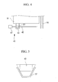
- the dust box 137 is tapered, in at least the area engaged with a split nut 43, so that the inner side walls of the dust box 137 are disposed further away from each other toward the upper side of the side walls.
- the structure is not limited to this, however; the entire area of the side walls may be tapered in a manner similar to the first embodiment.
- the operation of the air conditioner 101 in a cooling mode and a heating mode and the indoor air flow inside the indoor unit 103 are the same as those according to the first embodiment, and, therefore, descriptions thereof are not repeated here.
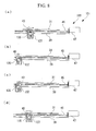
- the brush unit 135 and the dust box 137 move to an area at the end of the driving screw 45 where the air filter 31 is not disposed.
- the brush unit 135 that has moved to the edge is rotated by substantially 180° so that the dust is pushed downward into the dust box 137.
- the detecting unit 51 detects the amount of dust collected in the dust box 137.
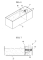
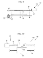
- Fig. 9 illustrates the removal of dust in the dust box 137 illustrated in Fig. 8 .
- the dust in the dust box 137 is removed. More specifically, as shown in Fig. 9 , the brush unit 135 and the dust box 137 are lowered together with the air filter 31 by raising units 57 in the same manner as in the first embodiment. The description of this lowering operation is not repeated.
- the dust by rotating the brush unit 135 by half a revolution, the dust can be pushed downward into the dust box 137. In this way, the dust can be prevented from falling out of the dust box 137 and into the room.
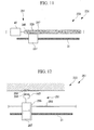
- the basic structure of an air conditioner according to this embodiment is the same as that according to the first embodiment. Only the engagement structure of the dust box and the driving unit differs from the first embodiment. Therefore, in this embodiment, the engagement structure of the dust box and the driving unit will be described with reference to Fig. 10 , and descriptions of the other structures will not be repeated.
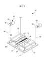
- An indoor unit 153 of an air conditioner 151 includes a dust box (collecting unit) 187 accommodating a brush unit (not shown in the drawing) configured to remove dust attached to the air filter 31 and a driving unit 191 configured to drive the dust box 187 along the air filter 31, as shown in Fig. 10 .
- the dust box 187 has a protrusion 189 protruding upward in at least the area where the driving unit 191 is engaged with the dust box 187.
- the protrusion 189 has inclined surfaces that come closer to each other toward the top.
- the split nut 193 has a depression 195 that is engaged with the protrusion 189 of the dust box 187.
- the depression 195 is formed so that it matches the shape of the protrusion 189.
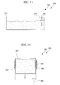
- the basic structure of an air conditioner according to this embodiment is the same as that according to the first embodiment. Only the engagement structure of the dust box and the driving unit differs from the first embodiment. Therefore, in this embodiment, the engagement structure of the dust box and the driving unit will be described with reference to Fig. 11 , and descriptions of the other structures will not be repeated.
- the driving unit 241 includes a driving screw 245 configured to drive the dust box 237 and a driving motor 47 configured to rotationally drive the driving screw 245.
- the driving screw 245 has a thread 247 with spiral protrusions.
- the operation of the air conditioner 201 in a cooling mode and a heating mode and the indoor air flow inside the indoor unit 203 are the same as those according to the first embodiment, and, therefore, descriptions thereof are not repeated here.
- the driving screw 245 When dust attaches to the air filter 31, as shown in Fig. 11 , the driving screw 245 is rotationally driven by the driving motor 47. The rotation of the driving screw 245 is converted into a movement in the direction along the driving screw 245 by the engagement of the thread 247 and the female screw section 239.
- the dust box 237 moves together with the brush unit to scrape off dust attached to the air filter 31. The scraped off dust is collected in the dust box 237.
- the dust inside the dust box 237 is removed.
- the dust box 237 and the driving screw 245 are disengaged, and the driving unit 241 is left inside the indoor unit 203.
- the dust box 237 and the driving screw 245 of the driving unit 241 are engaged by the female screw section 239 and the thread 247. Therefore, by lowering and raising the dust box 237, the dust box 237 and the driving unit 241 can be easily disengaged and engaged.
- the driving unit 241 remains inside the indoor unit 203 when the dust box 237 is lowered or raised, the load applied to the raising units 57 when lifting and lowering the dust box 237 can be reduced.
- the basic structure of an air conditioner according to this embodiment is the same as that according to the first embodiment. Only the structure of the dust box and the driving unit differs from the first embodiment. Therefore, in this embodiment, the structure of the dust box and the driving unit will be described with reference to Fig. 12 , and descriptions of the other structures are not repeated.
- Fig. 12 illustrates the structure of a dust box and a driving unit in an indoor unit according to this embodiment.
- an indoor unit 253 of an air conditioner 251 includes a dust box (collecting unit) 287 accommodating a brush unit (not shown in the drawing) configured to remove dust attached to an air filter 31 and a driving unit 291 configured to drive the dust box 287 along the air filter 31.
- the driving unit 291 includes a rail 293, a moving unit 295 that reciprocates along the rail 293, and a wiring unit 297 that extends from the moving unit 295 to the indoor unit 253.
- One of the ends of the wiring unit 297 is fixed to the moving unit 295, and the other end is attached to the indoor unit 253 by the magnetic force of a magnet 299.
- the entire driving unit 291 is disposed on an air inlet grill 19 and is raised and lowered together with the air inlet grill 19.
- the dust box 287 accommodates the brush unit and the moving unit 295.
- the operation of the air conditioner 251 in a cooling mode and a heating mode and the indoor air flow inside the indoor unit 253 are the same as those according to the first embodiment, and, therefore, descriptions thereof are not repeated here.
- the moving unit 295 moves along the rail 293.
- the dust box 287 moves together with the brush unit so as to scrape off the dust attached to the air filter 31. The scraped off dust is collected in the dust box 287.
- the magnetic force of the magnet 299 is applied to the wiring unit 297 to guide the wiring unit 297 to a predetermined connecting part so that the wiring unit 297 is attached to the indoor unit 253.
- the indoor unit 253 and the driving unit 291 are attached by the magnet 299 of the wiring unit 297. Therefore, when the driving unit 291 is lowered and raised, the indoor unit 253 and the driving unit 291 can be easily separated and connected at the magnet of the wiring unit 297.
- the driving unit 291 is lowered and raised together with the dust box 287, the dust box 287 and the driving unit 291 are not misaligned, and the dust box 287 can be reliably driven.
- the basic structure of an air conditioner according to this embodiment is the same as that according to the first embodiment. Only the structure of the detecting unit of the dust box differs from the first embodiment. Therefore, in this embodiment, the structure of the detecting unit of the dust box will be described with reference to Fig. 13 , and descriptions of the other structures are not repeated.
- Fig. 13 illustrates the structure of a detecting unit of a dust box in an indoor unit according to this embodiment.
- an indoor unit 303 of an air conditioner 301 includes a dust box (collecting unit) 337 accommodating a brush unit (not shown in the drawing) configured to remove dust attached to an air filter 31 and a detecting unit 339 configured to detect the amount of dust accumulated in the dust box 337.
- a cover 341 configured to cover part of an opening is disposed, and, on the lower surface of the cover 341, the detecting unit 339 configured to detect the amount of dust is disposed.
- the detecting unit 339 may be a contact sensor configured to detect the amount of dust by contacting the dust.
- the operation of the air conditioner 301 in a cooling mode and a heating mode and the indoor air flow inside the indoor unit 303 are the same as those according to the first embodiment, and, therefore, descriptions thereof are not repeated here.
- the dust box 337 When dust is collected in the dust box 337, the dust accumulates inside the dust box 337. The accumulated dust comes into contact with the detecting unit 339 disposed below the cover 341. The detecting unit 339 outputs a dust-detection signal.
- the operator can remove the dust collected in the dust box 337 on the basis of this dust-detection signal.
- the basic structure of an air conditioner according to this embodiment is the same as that according to the first embodiment. Only the structure of the detecting unit of the dust box differs from the first embodiment. Therefore, in this embodiment, the structure of the detecting unit of the dust box will be described with reference to Fig. 14 , and descriptions of the other structures are not repeated.
- Fig. 14 illustrates the structure of a detecting unit of a dust box in an indoor unit according to this embodiment.
- an indoor unit 353 of an air conditioner 351 includes a dust box (collecting unit) 387 accommodating a brush unit (not shown in the drawing) configured to remove dust attached to an air filter 31 and a detecting unit 389 configured to detect the amount of dust accumulated in the dust box 387.
- bellow-like folded sections 391 and support members 393 holding the folded sections 391 in contracted positions are provided.
- the support members 393 may be strips of adhesive tape.
- the detecting unit 389 is disposed below the dust box 387 with a predetermined gap provided between the detecting unit 389 and the dust box 387.
- the detecting unit 389 is capable of detecting the lowering of the bottom surface of the dust box 387.
- the detecting unit 389 may be a contact sensor capable of detecting the button surface of the dust box 387 by contact.
- the air conditioner 351 having the above-described structure will be described below.
- the operation of the air conditioner 351 in a cooling mode and a heating mode and the indoor air flow inside the indoor unit 353 are the same as those according to the first embodiment, and, therefore, descriptions thereof are not repeated here.
- the bottom surface of the dust box 387 is pushed downward.
- the support members 393 detach and the folded sections 391 extend, causing the bottom surface of the dust box 387 to be lowered.
- the bottom surface of the dust box 387 When the bottom surface of the dust box 387 is lowered, the bottom surface contacts the detecting unit 389, and the detecting unit 389 outputs a detection signal.
- the operator can remove the dust collected in the dust box 387 on the basis of this detection signal.
- the detecting unit 389 detects the bottom surface of the dust box 387 that is lowered by the dust collected in the dust box 387, the amount of dust can be detected reliably compared to when the dust is directly detected.
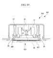
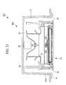
- the basic structure of an air conditioner according to this embodiment is the same as that according to the first embodiment. Only the structures of the air inlet grill, the dust box, and its vicinity differ from the first embodiment. Therefore, in this embodiment, the structures of the air inlet grill, the dust box, and its vicinity will be described with reference to Figs. 15 to 18 , and descriptions of the other structures are not repeated.
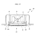
- Fig. 15 illustrates the structure of an indoor unit according to this embodiment.
- an indoor unit 403 of an air conditioner 401 includes a top panel 14 in the lower area, a chassis 15 embedded in the ceiling, an air filter 431 provided on an air inlet section 16 of the top panel 14 so as to take in indoor air, an indoor fan 21 configured to take in and send out indoor air, and an indoor heat-exchanger 23 configured to carry out heat exchange between the indoor air and a refrigerant.
- a fan motor 25 configured to drive the indoor fan 21 is disposed.
- the indoor heat-exchanger 23 is disposed around the indoor fan 21 and the fan motor 25.
- a bellmouth 27 configured to adjust the flow of the indoor air to the indoor fan 21 is disposed.
- the air filter 431 is disposed.
- air outlets 29 configured to let indoor air that has entered the indoor fan 21 and has passed through the indoor heat-exchanger 23 flow out from the chassis 15 are provided.
- Fig. 16 is a partial perspective view illustrating the structure of a raising unit, the air filter 431, and a dust box 437 of the indoor unit 403 illustrated in Fig. 15 .
- the air filter 431 includes a filter surface 433a that catches dust in the indoor air and a frame 433b supporting the filter surface 433a.
- a brush unit 35 configured to remove the dust attached to the filter surface 433a and the dust box (collecting unit) 437 configured to cover the brush unit 35 from below are disposed.
- Fig. 17 is a perspective view illustrating the structures of the dust box 437 and the brush unit 35 illustrated in Fig. 16 .
- the air conditioner 401 having the above-described structure will be described below.
- the operation of the air conditioner 401 in a cooling mode and a heating mode and the indoor air flow inside the indoor unit 403 are the same as those according to the first embodiment, and, therefore, descriptions thereof are not repeated here.
- the indoor unit is embedded in the ceiling.
- the indoor unit is not limited to a ceiling-embedded type indoor unit and may be any other type of indoor unit that is installed on the ceiling, such as a ceiling-suspended indoor unit.
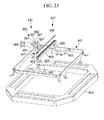
- the support members 643 may be provided on the frame 641 so as to support the driving motor 635 and the reciprocating unit 637.
- the supporting structure is not limited to this configuration, and the driving motor 635 and the reciprocating unit 637 may be directly supported by the frame 641 without providing the support members 643.
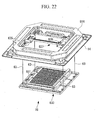
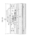
- the upper transmitting unit 639 includes a driving-force transmitting unit 653 that receives the reciprocative driving force from the worm gear 647, an adjusting unit (disengagement-prevention unit) 655 that holds the driving rack gear 649 against the driving-force transmitting unit 653 (refer to Fig. 24 ), and screws (disengagement-prevention units) 657 configured to join the driving-force transmitting unit 653 and the adjusting unit 655.
- a driving-force transmitting unit 653 that receives the reciprocative driving force from the worm gear 647
- an adjusting unit (disengagement-prevention unit) 655 that holds the driving rack gear 649 against the driving-force transmitting unit 653 (refer to Fig. 24 )
- screws (disengagement-prevention units) 657 configured to join the driving-force transmitting unit 653 and the adjusting unit 655.
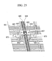
- Fig. 25 is a partial perspective view illustrating the engagement of the upper transmitting unit 639 and the worm gear 647.
- Fig. 26 is a partial exploded perspective view illustrating the structure of the air filter 631 and the cleaning unit 633 provided on the air inlet grill 19 shown in Fig. 22 .
- the air filter 631 is disposed in substantially the center of the base 619.
- the lower transmitting unit 675 is disposed above (upper side in Fig. 26 ) the air filter 631.
- the cleaning unit 633 is disposed below (lower side in Fig. 26 ) the air filter 631.
- the cleaning unit 633 includes the rotary brush (dust-removing unit) 685 configured to remove dust collected by the air filter 631 and the dust box (collecting unit) 687 configured to temporarily store dust removed by the rotary brush 685.
- the sliding units 695 By contacting the dust box 687, the sliding units 695 transmit the reciprocative driving force from the dust box 687 to the rotary brush 685. Depressions in which the dust box 687 is fitted are provided on the sliding units 695. By engaging the depressions and the dust box 687, the relative positions of the rotary brush 685 and the dust box 687 are set. To improve slidability, it is desirable to construct the sliding units 695 of a material different from the material constituting the dust box 687. For example, if the dust box 687 is composed of acrylonitrile butadiene styrene resin (ABS resin), it is desirable to compose the sliding unit 695 of Duracon resin (polyacetal resin).
- ABS resin acrylonitrile butadiene styrene resin
- Duracon resin polyacetal resin
- Fig. 30 is a cross-sectional view illustrating the structure of the rotary brush 685 and the dust box 687 of the cleaning unit 633 illustrated in Fig. 26 .
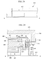
- the main body 697 includes brackets 701 that are engaged with the lower transmitting unit 675 and rollers 703 that are configured to support the main body 697 in a reciprocating manner, as shown in Fig. 29 , and also includes scrapers 705 configured to scrape off dust from the brush unit 691, as shown in Fig. 30 .
- the scrapers 705 are disposed on the inner surface of the through-hole in the main body 697 such that they extend inward and are disposed along the longitudinal direction (i.e., in the direction orthogonal to the surface of the page of Fig. 30 ) of the main body 697 at equal intervals.
- the brush unit 691 of the rotary brush 685 moves through the gap between the scrapers 705 so that dust attached to the brush unit 691 is removed.
- the sides of the scrapers 705 opposing the edge of the air filter 631 i.e., the upper side of the scrapers 705 in Fig. 30
- Dust is collected toward the central area by the inclined sides of the scrapers 705 and is sent to the retention unit 699.
- Fig. 31 is a cross-sectional view illustrating another structure of the scrapers 705 illustrated in Fig. 30 .
- the retention unit 699 covers the rotary brush 685 from below, as shown in Fig. 26 , and is engaged with the main body 697, as shown in Fig. 30 . Dust removed from the air filter 631 by the rotary brush 685 is temporarily stored in the space defined by the retention unit 699, the main body 697, and the rotary brush 685.
- the lower transmitting unit 675 is a rod-shaped member. On both ends of the lower transmitting unit 675, grippers 709 configured to hold the brackets 701 of the cleaning unit 633 are provided.
- a lower engagement part 711 that is engaged with the upper engagement parts 669 of the upper transmitting unit 639 is provided.
- the lower engagement part 711 has a smaller width compared to the other parts of the lower transmitting unit 675. This narrow part is engaged with the upper depression 671 of the upper engagement part 669.
- lower depression 713 that are engaged with the cleaning unit 633 and hold the brackets 701 are provided at the tips of the grippers 709.
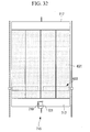
- Fig. 32 is a plan view illustrating the structure of a dust-amount detecting unit provided on the base 619 of the air inlet grill 19 illustrated in Fig. 22 .
- Fig. 33 is a cross-sectional view illustrating the structure of the dust-amount detecting unit illustrated in Fig. 32 .
- a dust-amount detecting unit 715 includes covers 717 configured to cover the openings of the cleaning unit 633, a fan 719 configured to take in air, and a flow sensor (sensor) 721 configured to detect the flow rate of the air taken in by the fan 719.
- the covers 717 are disposed opposite to the outer edges in the movement directions (vertical direction in Fig. 32 ) of the cleaning unit 633 of the air filter 631. As shown in Fig. 33 , the covers 717 are disposed on substantially the same plane as the air filter 631.
- Through-holes having a small diameter are formed in components such as the retention unit 699 of the cleaning unit 633 so as to allow air to flow in from the outside.
- the operation of the air conditioner 601 in a cooling mode and a heating mode and the indoor air flow inside the indoor unit 603 are the same as those according to the first embodiment, and, therefore, descriptions thereof are not repeated here.
- the rotational driving force of the driving motor 635 is transmitted to the driving shaft 645, and the worm gear 647 is rotationally driven.
- the worm gear 647 engaged with the driving rack gear 649 is driven in a reciprocating manner along the driving shaft.
- the driving direction of the worm gear 647 is controlled by the rotational direction of the driving motor 635.
- the reciprocating movement of the worm gear 647 is transmitted to the upper transmitting unit 639, and the upper transmitting unit 639 is moved in a reciprocating manner together with the worm gear 647.
- the cylindrical portions 651 of the worm gear 647 are in contact with the contact units 665 of the upper transmitting unit 639, and, therefore, the worm gear 647 does not move more than a predetermined distance away from the driving rack gear 649. Since the driving rack gear 649 is interposed between the upper transmitting unit 639 and the adjusting unit 655, the upper transmitting unit 639 does not move more than a predetermined distance away from the driving rack gear 649.
- the reciprocating movement transmitted to the upper transmitting unit 639 is transmitted from the upper transmitting unit 639 to the lower transmitting unit 675. Since the pressing plate 673 of the upper transmitting unit 639 is in contact with the upper surface of the lower transmitting unit 675, the relative positions of the upper transmitting unit 639 and the lower transmitting unit 675 do not change even when the reciprocating movement is transmitted.
- the reciprocating movement of the lower transmitting unit 675 is transmitted from the grippers 709 to the brackets 701 of the cleaning unit 633 disposed on the lower surface of the air filter 631.
- the reciprocating movement transmitted to the brackets 701 is transmitted from the dust box 687 to the rotary brush 685.
- the rotary brush 685 moves in a reciprocating manner on the lower surface side of the air filter 631 and, at the same time, is rotationally driven by engagement of the pinion gears 693 and the rotary rack gears 677.
- the reciprocating and rotational movements of the rotary brush 685 cause the brush unit 691 of the rotary brush 685 to wipe the entire surface of the air filter 631 on the air inlet side so as to remove the dust collected on the air filter 631.
- the speed of the reciprocating movement of the rotary brush 685 and the rotational speed of the tips of the brush unit 691 differ by a predetermined value. This difference in speed enables the brush unit 691 to wipe the entire surface of the air filter 631.
- the diameters of the pinion gears 693 and the brush unit 691 may be set to have a predetermined ratio.
- the dust attached to the brush unit 691 is scraped off from the brush unit 691 when the brush unit 691 passes through the gap between the scrapers 705.
- the dust scraped off by the scrapers 705 drops through the gap between the scrapers 705 to the retention unit 699.
- the cleaning unit 633 that has removed dust from the air filter 631 is moved from an area where the air filter 631 is disposed to an area where one of the covers 717 of the dust-amount detecting unit 715 is disposed.
- the fan 719 rotates, and air is sucked into the cleaning unit 633.
- the flow sensor 721 detects the flow rate of the air sucked in by the fan 719 so as to estimate the amount of dust stored, based on the flow rate. While the cleaning unit 633 is cleaning the air filter 631, the fan 719 is turned off, and the amount of dust is not detected.
- the flow rate of the air sucked in by the fan 719 is reduced, whereas, if a small amount of dust is stored in the retention unit 699, the flow rate of the air sucked in by the fan 719 is increased.
- the flow sensor 721 configured to detect the flow rate of the air sucked in by the fan 719 may be provided on the dust-amount detecting unit 715 or, instead, a pressure-loss sensor configured to detect the pressure loss (pressure) in the air sucked in by the fan 719 may be provided.
- the type of sensor is not limited. In the case where a pressure-loss sensor is used, if a large amount of dust is stored in the retention unit 699, the pressure loss in the air flow sucked in by the fan 719 is large, whereas, if a small amount of dust is stored in the retention unit 699, the pressure loss in the air flow sucked in by the fan 719 is small.
- the air inlet grill 19 includes the air filter 631, the cleaning unit 633, and the lower transmitting unit 675, by lowering the air inlet grill 19, the air filter 631, the cleaning unit 633, and the lower transmitting unit 675 are also simultaneously lowered from the top panel 14.
- the transmission path of the driving force from the driving motor 635 to the cleaning unit 633 is cut off between the upper transmitting unit 639 and the lower transmitting unit 675.
- the upper transmitting unit 639 and the lower transmitting unit 675 are disengaged by lowering the lower transmitting unit 675 together with the air filter 631 and so on.
- the cleaning unit 633 is moved to one of the edges (the right edge in Fig. 22 ) of the air filter 631.
- Fig. 34 illustrates a method of removing the cleaning unit 633 from the air filter 631 illustrated in Fig 22 .
- the lower transmitting unit 675 engaged with the cleaning unit 633 on the lowered air inlet grill 19 is removed. As shown in Fig. 29 , since the cleaning unit 633 and the lower transmitting unit 675 are engaged by the grippers 709 holding the brackets 701 from above, by pulling the grippers 709 upward, the lower transmitting unit 675 can be removed from the cleaning unit 633.
- Fig. 35 illustrates the method of removing the cleaning unit 633 from the air filter 631 illustrated in Fig. 22 .
- the air filter 631 is pivoted on a first edge (the right edge in Fig. 35 ) so as to lift a second edge (the left edge in Fig. 35 ).
- the cleaning unit 633 disposed on the lower surface side of the air filter 631 is exposed.
- the cleaning unit 633 is removed upward from the air inlet grill 19.
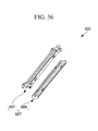
- Fig. 36 illustrates the method of removing the cleaning unit 633 from the air filter 631 illustrated in Fig. 22 .
- the cleaning unit 633, the air filter 631, and the air inlet grill 19 are re-assembled by following the above-described steps in the reversed order. Then, the air inlet grill 19 is raised.
- the driving force generated at the driving motor 635 can be transmitted to the cleaning unit 633 via the reciprocating unit 637, the upper transmitting unit 639, and the lower transmitting unit 675. Therefore, the cleaning unit 633 can be moved along the surface of the air filter 631 on the air inlet side by the driving force transmitted from the driving motor 635, and the rotary brush 685 can remove dust collected on the air filter 631.
- the driving motor 635, the reciprocating unit 637, and the upper transmitting unit 639 are disposed on the frame 641 disposed on the top panel 14.
- the cleaning unit 633 and the lower transmitting unit 675 are disposed on the air filter 631.
- the upper transmitting unit 639 and the lower transmitting unit 675 are detachably engaged with each other. Therefore, both detachment of the air inlet grill 19, including the air filter 631, from the chassis 15 and driving of the cleaning unit 633 by the driving motor 635 can be achieved.
- the upper transmitting unit 639 and the lower transmitting unit 675 are disengaged when the air inlet grill 19 is detached from the chassis 15, the detachment of the air inlet grill 19 is not hindered. Moreover, since the upper transmitting unit 639 and the lower transmitting unit 675 are engaged again when the air inlet grill 19 that has been detached is re-attached to the chassis 15, the driving of the cleaning unit 633 by the driving motor 635 is not hindered.
- the air filter 631 Since the lower transmitting unit 675 is disposed on the air outlet side of the air filter 631, the air filter 631 is interposed between the cleaning unit 633 and the lower transmitting unit 675. Therefore, the air filter 631, the cleaning unit 633, and the lower transmitting unit 675 can be detached from the chassis 15 as a unit.
- the air filter 631 and the cleaning unit 633 can be removed independently from the unit formed of the air filter 631, the cleaning unit 633, and the lower transmitting unit 675 removed from the chassis 15. Therefore, maintenance of the cleaning unit 633 and the air filter 631 can be easily carried out.
- the rotary brush 685 includes the rotary shaft 689 on which the rotary brush 685 rotates around the longitudinal axis thereof and the brush unit 691 that extends in the radial direction of the rotary shaft 689, by rotating the rotary shaft 689, the brush unit 691 rotates to remove dust collected on the air filter 631.
- the dust box 687 covers the rotary brush 685 and is capable of temporarily storing the dust removed from the air filter 631 by the rotary brush 685. Since the dust box 687 has an opening where the rotary brush 685 can contact the air filter 631, by letting the rotary brush 685 come into contact with the air filter 631, the dust collected on the air filter 631 can be removed by the rotary brush 685.
- the driving force that moves the cleaning unit 633 along the surface of the air filter 631 is converted into a rotational driving force for rotating the rotary brush 685.
- the rotary brush 685 also moves along the surface of the air filter 631.
- the driving force that moves the rotary brush 685 along the surface of the air filter 631 is converted into a rotational driving force for rotating the rotary brush 685.
- the pinion gears 693 are provided at both ends of the rotary shaft 689, the rotational driving force for rotating the rotary brush 685 is generated at both ends of the rotary shaft 689. Therefore, the rotary brush 685 can be stably rotated compared to a case in which the rotational driving force is generated at only one end of the rotary shaft 689.
- dust attached to the rotary brush 685 can be removed. More specifically, dust attached to the brush unit 691 is removed when the brush unit 691 passes through the gap between the scrapers 705 while the rotary brush 685 is rotating.
- the dust removed by the scrapers 705 is temporarily stored inside the dust box 687.
- the scrapers 705 function as covers that prevent the dust temporarily stored in the dust box 687 from escaping.
- the entire surface of the air filter 631 can be cleaned. More specifically, since the rotational speed of the tips of the brush unit 691 and the movement speed of the rotary brush 685 have a predetermined difference, the tips of the brush unit 691 are capable of wiping the surface of the air filter 631 at a predetermined speed. Therefore, the brush unit 691 of the rotary brush 685 contacts the entire air filter 631 and cleans the entire surface of the air filter 631 more thoroughly compared to when the difference between the rotational speed of the tips of the brush unit 691 and the movement speed of the rotary brush 685 is small.
- the sliding units 695 configured to reduce sliding resistance caused by the rotation of the rotary shaft 689 are provided between the rotary shaft 689 and the dust box 687, the life of the rotary shaft 689 and the life of the dust box 687 can be extended. More specifically, by providing the sliding units 695, friction generated at the contact area of the rotary shaft 689 and the dust box 687 is reduced, and the amount of abrasion at the contact area is reduced. Therefore, the life of the rotary brush 685 and the life of the dust box 687 can be extended.
- the dust-amount detecting unit 715 Since the dust-amount detecting unit 715 is provided, the amount of dust stored in the dust box 687 can be detected. Therefore, the dust box 687 can be prevented from being filled with dust, and a reduction in the ability to remove dust by the cleaning unit 633 can be prevented.
- the amount of dust stored in the dust box 687 can be detected by the fan 719 and the flow sensor 721 included in the dust-amount detecting unit 715. If a small amount of dust is stored in the dust box 687, the flow rate or the pressure of the air passing through the dust box 687 increases. On the contrary, if a large amount of dust is stored in the dust box 687, the flow rate or the pressure of the air passing through the dust box 687 decreases. By detecting the flow rate or pressure of the air with the flow sensor 721, the amount of dust stored in the dust box 687 can be estimated.
- the cleaning unit 633 can be stably moved. In other words, the same amount of driving force can be transmitted to both ends of the cleaning unit 633 and the cleaning unit 633 can be stably driven compared to a method in which the driving force is transmitted to substantially the central area of the cleaning unit 633.
- the number of reciprocating units 637 provided can be reduced and the size of the indoor unit 603 can be reduced compared to a method in which the driving force is transmitted to substantially the central area of the cleaning unit 633.
- the worm gear 647 engaged with the driving rack gear 649 is rotationally driven by the driving shaft 645, the worm gear 647 is reciprocated in the direction parallel to the driving rack gear 649. Since the reciprocating movement of the worm gear 647 is transmitted to the cleaning unit 633 via the upper transmitting unit 639 and the lower transmitting unit 675, the cleaning unit 633 is reciprocated.
- the upper transmitting unit 639 can be prevented from disengaging from the worm gear 647. For example, when sliding load generated between the worm gear 647 and the upper transmitting unit 639 and a resistive force generated when the cleaning unit 633 moves are applied to the upper transmitting unit 639, the upper transmitting unit 639 is prevented from disengaging from the worm gear 647.
- the air conditioner according to the above-described embodiments includes one indoor unit and one outdoor unit.
- the number of indoor and outdoor units is not limited thereto, and the air conditioner may include a plurality of indoor units and one outdoor unit or may include a plurality of outdoor units and one indoor unit.
Landscapes
- Engineering & Computer Science (AREA)
- Chemical & Material Sciences (AREA)
- Combustion & Propulsion (AREA)
- Mechanical Engineering (AREA)
- General Engineering & Computer Science (AREA)
- Physics & Mathematics (AREA)
- Thermal Sciences (AREA)
- Air Filters, Heat-Exchange Apparatuses, And Housings Of Air-Conditioning Units (AREA)
- Air Conditioning Control Device (AREA)
- Filtering Of Dispersed Particles In Gases (AREA)
Applications Claiming Priority (3)
| Application Number | Priority Date | Filing Date | Title |
|---|---|---|---|
| JP2005195208 | 2005-07-04 | ||
| JP2005377295A JP4418427B2 (ja) | 2005-07-04 | 2005-12-28 | 室内機ユニットおよび空気調和機 |
| EP06110322.2A EP1741992B1 (de) | 2005-07-04 | 2006-02-23 | Innenraumeinheit einer Klimaanlage |
Related Parent Applications (3)
| Application Number | Title | Priority Date | Filing Date |
|---|---|---|---|
| EP06110322.2 Division | 2006-02-23 | ||
| EP06110322.2A Division-Into EP1741992B1 (de) | 2005-07-04 | 2006-02-23 | Innenraumeinheit einer Klimaanlage |
| EP06110322.2A Division EP1741992B1 (de) | 2005-07-04 | 2006-02-23 | Innenraumeinheit einer Klimaanlage |
Publications (3)
| Publication Number | Publication Date |
|---|---|
| EP2574859A2 true EP2574859A2 (de) | 2013-04-03 |
| EP2574859A3 EP2574859A3 (de) | 2014-08-20 |
| EP2574859B1 EP2574859B1 (de) | 2016-11-30 |
Family
ID=37067484
Family Applications (4)
| Application Number | Title | Priority Date | Filing Date |
|---|---|---|---|
| EP06110322.2A Expired - Lifetime EP1741992B1 (de) | 2005-07-04 | 2006-02-23 | Innenraumeinheit einer Klimaanlage |
| EP12199412.3A Expired - Lifetime EP2574857B1 (de) | 2005-07-04 | 2006-02-23 | Innenraumeinheit und Klimaanlage |
| EP12199462.8A Expired - Lifetime EP2574859B1 (de) | 2005-07-04 | 2006-02-23 | Innenraumeinheit und Klimaanlage |
| EP12199428.9A Expired - Lifetime EP2574858B1 (de) | 2005-07-04 | 2006-02-23 | Innenraumeinheit und Klimaanlage |
Family Applications Before (2)
| Application Number | Title | Priority Date | Filing Date |
|---|---|---|---|
| EP06110322.2A Expired - Lifetime EP1741992B1 (de) | 2005-07-04 | 2006-02-23 | Innenraumeinheit einer Klimaanlage |
| EP12199412.3A Expired - Lifetime EP2574857B1 (de) | 2005-07-04 | 2006-02-23 | Innenraumeinheit und Klimaanlage |
Family Applications After (1)
| Application Number | Title | Priority Date | Filing Date |
|---|---|---|---|
| EP12199428.9A Expired - Lifetime EP2574858B1 (de) | 2005-07-04 | 2006-02-23 | Innenraumeinheit und Klimaanlage |
Country Status (3)
| Country | Link |
|---|---|
| EP (4) | EP1741992B1 (de) |
| JP (1) | JP4418427B2 (de) |
| ES (4) | ES2610999T3 (de) |
Cited By (1)
| Publication number | Priority date | Publication date | Assignee | Title |
|---|---|---|---|---|
| CN108291728A (zh) * | 2015-12-02 | 2018-07-17 | 豪威株式会社 | 空气净化器 |
Families Citing this family (64)
| Publication number | Priority date | Publication date | Assignee | Title |
|---|---|---|---|---|
| JP4623098B2 (ja) * | 2007-02-09 | 2011-02-02 | ダイキン工業株式会社 | 空気調和装置の室内機 |
| JP5103926B2 (ja) * | 2007-02-09 | 2012-12-19 | ダイキン工業株式会社 | 空気調和装置の室内ユニット |
| WO2008096807A1 (ja) * | 2007-02-09 | 2008-08-14 | Daikin Industries, Ltd. | 空気調和装置の室内機 |
| WO2008096536A1 (ja) * | 2007-02-09 | 2008-08-14 | Daikin Industries, Ltd. | 空気調和装置の室内ユニット |
| US8303677B2 (en) * | 2007-02-09 | 2012-11-06 | Daikin Industries, Ltd. | Indoor unit of air conditioner |
| JP4952299B2 (ja) * | 2007-02-28 | 2012-06-13 | ダイキン工業株式会社 | 空気調和装置の室内ユニット |
| JP2008209100A (ja) * | 2007-02-28 | 2008-09-11 | Daikin Ind Ltd | 空気調和装置の室内ユニット |
| CN101290152B (zh) * | 2007-04-18 | 2010-05-26 | 海尔集团公司 | 过滤网自清洁装置 |
| JP4973312B2 (ja) * | 2007-05-18 | 2012-07-11 | ダイキン工業株式会社 | 空気調和装置の室内ユニット |
| JP2009014277A (ja) * | 2007-07-05 | 2009-01-22 | Daikin Ind Ltd | 空気調和装置の室内ユニット |
| JP4967895B2 (ja) * | 2007-07-25 | 2012-07-04 | ダイキン工業株式会社 | 空気調和装置の室内ユニット |
| JP5060868B2 (ja) * | 2007-08-21 | 2012-10-31 | 株式会社コーワ | 空気調和機用清掃装置と空気調和機 |
| KR100902283B1 (ko) * | 2007-10-23 | 2009-06-10 | 범아건설 주식회사 | 천정형 에어컨 |
| JP4910995B2 (ja) * | 2007-11-13 | 2012-04-04 | パナソニック株式会社 | 空気調和機 |
| KR101173367B1 (ko) | 2007-12-11 | 2012-08-10 | 다이킨 고교 가부시키가이샤 | 공기조화장치의 실내유닛 |
| US9103559B2 (en) | 2007-12-19 | 2015-08-11 | Daikin Industries, Ltd. | Indoor unit of air conditioner |
| JP4416034B2 (ja) | 2007-12-19 | 2010-02-17 | ダイキン工業株式会社 | 空気調和装置の掃除ユニット |
| JP4752915B2 (ja) * | 2008-01-10 | 2011-08-17 | ダイキン工業株式会社 | 空気調和装置の室内ユニット |
| JP4661881B2 (ja) * | 2008-01-25 | 2011-03-30 | ダイキン工業株式会社 | 空調機の室内ユニット |
| KR101197899B1 (ko) | 2008-01-25 | 2012-11-05 | 다이킨 고교 가부시키가이샤 | 공조기의 실내 유닛 |
| KR101329755B1 (ko) * | 2008-01-28 | 2013-11-14 | 엘지전자 주식회사 | 천장형 공기조화기 |
| KR101321544B1 (ko) * | 2008-01-28 | 2013-10-25 | 엘지전자 주식회사 | 천장형 공기조화기 |
| JP4894773B2 (ja) * | 2008-02-05 | 2012-03-14 | ダイキン工業株式会社 | 空調室内機 |
| JP4883050B2 (ja) | 2008-02-05 | 2012-02-22 | ダイキン工業株式会社 | 空調室内機の可動パネル |
| JP5232497B2 (ja) * | 2008-02-21 | 2013-07-10 | 三菱重工業株式会社 | 空調用室内ユニット |
| JP5036607B2 (ja) * | 2008-03-21 | 2012-09-26 | 三菱電機株式会社 | 空気調和機 |
| JP5055194B2 (ja) * | 2008-04-24 | 2012-10-24 | 三菱重工業株式会社 | 室内機ユニットおよび空気調和機 |
| JP4772096B2 (ja) * | 2008-06-30 | 2011-09-14 | 三菱電機株式会社 | 天井埋込型空気調和機 |
| JP2010025415A (ja) * | 2008-07-17 | 2010-02-04 | Daikin Ind Ltd | 連結構造体、及びその連結構造体を備えた空調機 |
| JP4935774B2 (ja) * | 2008-07-18 | 2012-05-23 | ダイキン工業株式会社 | 天井設置型の空気調和機 |
| JP4488106B2 (ja) * | 2008-07-18 | 2010-06-23 | ダイキン工業株式会社 | 天井設置型の空気調和機 |
| JP4911137B2 (ja) * | 2008-07-29 | 2012-04-04 | ダイキン工業株式会社 | 空気調和装置 |
| JP5283448B2 (ja) * | 2008-08-12 | 2013-09-04 | 三洋電機株式会社 | 空気調和機 |
| JP2010043781A (ja) * | 2008-08-12 | 2010-02-25 | Sanyo Electric Co Ltd | 空気調和機 |
| JP5305800B2 (ja) * | 2008-09-17 | 2013-10-02 | 三洋電機株式会社 | 空気調和機 |
| JP5317613B2 (ja) * | 2008-09-26 | 2013-10-16 | 三洋電機株式会社 | 天井埋込型空気調和機 |
| JP5305808B2 (ja) * | 2008-09-26 | 2013-10-02 | 三洋電機株式会社 | 空気調和装置 |
| JP5329166B2 (ja) * | 2008-09-29 | 2013-10-30 | 三洋電機株式会社 | 空気調和機 |
| KR101035010B1 (ko) | 2009-02-25 | 2011-05-17 | 주식회사 엠.에스.라이팅 | 공기정화 및 조명 복합장치 |
| JP2011012936A (ja) * | 2009-07-06 | 2011-01-20 | Hitachi Appliances Inc | 天井埋込型空気調和機 |
| JP5320189B2 (ja) * | 2009-07-08 | 2013-10-23 | 三菱重工業株式会社 | 室内機ユニットおよび空気調和機 |
| JP5427496B2 (ja) * | 2009-07-08 | 2014-02-26 | 三菱重工業株式会社 | 室内機ユニットおよび空気調和機 |
| JP2011258707A (ja) * | 2010-06-08 | 2011-12-22 | Sanyo Electric Co Ltd | 電子機器及びフィルタユニット |
| JP4983973B2 (ja) * | 2010-10-18 | 2012-07-25 | ダイキン工業株式会社 | 空調システム |
| JP5108118B2 (ja) * | 2011-01-11 | 2012-12-26 | シャープ株式会社 | フィルタ清掃装置、ダストボックスおよび空気調和機 |
| JP2011174706A (ja) * | 2011-06-13 | 2011-09-08 | Daikin Industries Ltd | 空調室内機 |
| JP2011202949A (ja) * | 2011-06-13 | 2011-10-13 | Daikin Industries Ltd | 空調室内機 |
| JP5269224B2 (ja) * | 2012-03-02 | 2013-08-21 | 三菱電機株式会社 | 天井埋込型空気調和機 |
| KR102199380B1 (ko) | 2014-01-17 | 2021-01-06 | 엘지전자 주식회사 | 공기조화기 |
| CN104896708B (zh) * | 2014-03-05 | 2018-04-24 | 珠海格力电器股份有限公司 | 一种运动机构、天井机面板以及天井机 |
| JP6464019B2 (ja) * | 2015-04-20 | 2019-02-06 | 日立アプライアンス株式会社 | 空気清浄機 |
| EP3276277B1 (de) * | 2016-07-28 | 2020-04-08 | Daikin Industries, Ltd. | Filterreinigungsvorrichtung für eine klimaanlage und klimaanlage mit solch einer filterreinigungsvorrichtung |
| CN107265262A (zh) * | 2017-06-20 | 2017-10-20 | 菱电电梯有限公司 | 具有空气净化功能的载客电梯 |
| JP7539759B2 (ja) * | 2018-06-22 | 2024-08-26 | 三菱重工サーマルシステムズ株式会社 | フィルタ清掃ユニット及び空気調和機 |
| JP7330671B2 (ja) * | 2018-06-22 | 2023-08-22 | 三菱重工サーマルシステムズ株式会社 | フィルタ清掃ユニット及び空気調和機 |
| JP7134739B2 (ja) * | 2018-06-27 | 2022-09-12 | 三菱重工サーマルシステムズ株式会社 | フィルタ清掃ユニット及び空気調和機 |
| JP7679164B2 (ja) * | 2018-06-29 | 2025-05-19 | 三菱重工サーマルシステムズ株式会社 | フィルタ清掃ユニット及び空気調和機 |
| CN111174285B (zh) * | 2018-10-24 | 2021-07-23 | 重庆海尔空调器有限公司 | 一种可移动的空调、空调集群及智能家居系统 |
| KR102664218B1 (ko) | 2019-08-30 | 2024-05-09 | 삼성전자주식회사 | 공기조화기 |
| CN112438617B (zh) * | 2019-08-31 | 2022-01-21 | 宁波方太厨具有限公司 | 一种烤盘烤架复合运动机构及应用该机构的烤箱 |
| KR102372484B1 (ko) * | 2019-11-13 | 2022-03-10 | (주)에스엔 | 실외기용 공기정화 조립체 및 이를 구비하는 미세먼지 정화 시스템 |
| KR102216313B1 (ko) * | 2020-09-18 | 2021-02-17 | 주식회사 테크엔 | 미세먼지 정화기능을 구비한 엣지커버형 led 조명등 |
| CN112460728A (zh) * | 2020-11-03 | 2021-03-09 | 江苏楚锐环保科技有限公司 | 一种便于清理的空气净化设备 |
| CN117346240B (zh) * | 2023-09-12 | 2024-05-14 | 武汉格林美洁净技术工程有限公司 | 一种洁净室新风设备 |
Family Cites Families (7)
| Publication number | Priority date | Publication date | Assignee | Title |
|---|---|---|---|---|
| JP2718273B2 (ja) * | 1991-03-07 | 1998-02-25 | ダイキン工業株式会社 | 天井埋込形空気清浄機 |
| JP3297422B2 (ja) | 1996-07-26 | 2002-07-02 | 三菱重工業株式会社 | 空気調和機 |
| JPH1085534A (ja) * | 1996-09-19 | 1998-04-07 | Mitsubishi Denki Bill Techno Service Kk | 自動フィルタ清掃装置付空調機 |
| JPH11226331A (ja) * | 1998-02-18 | 1999-08-24 | Daikin Ind Ltd | 空気調和装置の室内機 |
| JP4271008B2 (ja) * | 2003-01-16 | 2009-06-03 | 三洋電機株式会社 | 天井埋込型空気調和装置 |
| JP2004340507A (ja) * | 2003-05-16 | 2004-12-02 | Matsushita Electric Ind Co Ltd | 天井埋め込み型空気調和機 |
| JP2005083612A (ja) * | 2003-09-05 | 2005-03-31 | Matsushita Electric Ind Co Ltd | 空気調和機 |
-
2005
- 2005-12-28 JP JP2005377295A patent/JP4418427B2/ja not_active Expired - Fee Related
-
2006
- 2006-02-23 EP EP06110322.2A patent/EP1741992B1/de not_active Expired - Lifetime
- 2006-02-23 EP EP12199412.3A patent/EP2574857B1/de not_active Expired - Lifetime
- 2006-02-23 ES ES06110322.2T patent/ES2610999T3/es not_active Expired - Lifetime
- 2006-02-23 ES ES12199428.9T patent/ES2611279T3/es not_active Expired - Lifetime
- 2006-02-23 EP EP12199462.8A patent/EP2574859B1/de not_active Expired - Lifetime
- 2006-02-23 ES ES12199412.3T patent/ES2609957T3/es not_active Expired - Lifetime
- 2006-02-23 ES ES12199462.8T patent/ES2611280T3/es not_active Expired - Lifetime
- 2006-02-23 EP EP12199428.9A patent/EP2574858B1/de not_active Expired - Lifetime
Cited By (1)
| Publication number | Priority date | Publication date | Assignee | Title |
|---|---|---|---|---|
| CN108291728A (zh) * | 2015-12-02 | 2018-07-17 | 豪威株式会社 | 空气净化器 |
Also Published As
| Publication number | Publication date |
|---|---|
| JP4418427B2 (ja) | 2010-02-17 |
| EP1741992A2 (de) | 2007-01-10 |
| ES2610999T3 (es) | 2017-05-04 |
| EP2574857B1 (de) | 2016-11-09 |
| EP1741992B1 (de) | 2016-11-23 |
| EP2574858B1 (de) | 2016-11-16 |
| EP2574858A2 (de) | 2013-04-03 |
| EP2574858A3 (de) | 2014-08-20 |
| ES2611280T3 (es) | 2017-05-08 |
| EP2574857A2 (de) | 2013-04-03 |
| EP1741992A3 (de) | 2012-08-01 |
| ES2609957T3 (es) | 2017-04-25 |
| ES2611279T3 (es) | 2017-05-08 |
| EP2574857A3 (de) | 2014-08-20 |
| EP2574859B1 (de) | 2016-11-30 |
| JP2007040689A (ja) | 2007-02-15 |
| EP2574859A3 (de) | 2014-08-20 |
Similar Documents
| Publication | Publication Date | Title |
|---|---|---|
| EP2574857B1 (de) | Innenraumeinheit und Klimaanlage | |
| JP4611448B2 (ja) | 室内機ユニットおよび空気調和機 | |
| JP5489890B2 (ja) | エアフィルタ自動清掃機構およびそれを備えた空気調和機 | |
| JP5327081B2 (ja) | 自動フィルタ清掃装置及び空気調和機 | |
| JP2010525285A (ja) | エアコンフィルターセルフクリーニング装置 | |
| JP5240960B2 (ja) | 空気調和機用清掃装置と空気調和機 | |
| JP5563047B2 (ja) | 室内機ユニットおよび空気調和機 | |
| JP6423626B2 (ja) | 空気調和機 | |
| CN111043656B (zh) | 空调室内机及具有其的空调系统 | |
| KR101116396B1 (ko) | 천장형 에어컨 필터 자동청소장치 | |
| JP2011021802A (ja) | 空気調和機の室内機 | |
| US7862636B2 (en) | Ceiling type air conditioner | |
| JP7679164B2 (ja) | フィルタ清掃ユニット及び空気調和機 | |
| KR20110116864A (ko) | 공기조화기 | |
| JP5291371B2 (ja) | 室内機ユニットおよび空気調和機 | |
| JP2009085504A (ja) | 空気調和機 | |
| JP7566450B2 (ja) | フィルタ清掃ユニット及び空気調和機 | |
| JP2010078231A (ja) | 空気調和装置 | |
| JP2009264658A (ja) | 室内機ユニットおよび空気調和機 | |
| JP5999944B2 (ja) | 空調室内機 | |
| KR20090044786A (ko) | 공기조화기 | |
| JP2008190835A (ja) | 空気調和機のフィルター装置及び空気調和機 | |
| JP2020003168A (ja) | フィルタ清掃ユニット及び空気調和機 |
Legal Events
| Date | Code | Title | Description |
|---|---|---|---|
| PUAI | Public reference made under article 153(3) epc to a published international application that has entered the european phase |
Free format text: ORIGINAL CODE: 0009012 |
|
| AC | Divisional application: reference to earlier application |
Ref document number: 1741992 Country of ref document: EP Kind code of ref document: P |
|
| AK | Designated contracting states |
Kind code of ref document: A2 Designated state(s): AT BE BG CH CY CZ DE DK EE ES FI FR GB GR HU IE IS IT LI LT LU LV MC NL PL PT RO SE SI SK TR |
|
| AX | Request for extension of the european patent |
Extension state: AL BA HR MK YU |
|
| PUAL | Search report despatched |
Free format text: ORIGINAL CODE: 0009013 |
|
| AK | Designated contracting states |
Kind code of ref document: A3 Designated state(s): AT BE BG CH CY CZ DE DK EE ES FI FR GB GR HU IE IS IT LI LT LU LV MC NL PL PT RO SE SI SK TR |
|
| AX | Request for extension of the european patent |
Extension state: AL BA HR MK YU |
|
| RIC1 | Information provided on ipc code assigned before grant |
Ipc: F24F 1/00 20110101AFI20140711BHEP Ipc: F24F 3/16 20060101ALI20140711BHEP Ipc: F24F 13/28 20060101ALI20140711BHEP |
|
| 17P | Request for examination filed |
Effective date: 20150218 |
|
| RBV | Designated contracting states (corrected) |
Designated state(s): AT BE BG CH CY CZ DE DK EE ES FI FR GB GR HU IE IS IT LI LT LU LV MC NL PL PT RO SE SI SK TR |
|
| GRAP | Despatch of communication of intention to grant a patent |
Free format text: ORIGINAL CODE: EPIDOSNIGR1 |
|
| INTG | Intention to grant announced |
Effective date: 20160512 |
|
| GRAJ | Information related to disapproval of communication of intention to grant by the applicant or resumption of examination proceedings by the epo deleted |
Free format text: ORIGINAL CODE: EPIDOSDIGR1 |
|
| GRAL | Information related to payment of fee for publishing/printing deleted |
Free format text: ORIGINAL CODE: EPIDOSDIGR3 |
|
| GRAS | Grant fee paid |
Free format text: ORIGINAL CODE: EPIDOSNIGR3 |
|
| GRAR | Information related to intention to grant a patent recorded |
Free format text: ORIGINAL CODE: EPIDOSNIGR71 |
|
| GRAJ | Information related to disapproval of communication of intention to grant by the applicant or resumption of examination proceedings by the epo deleted |
Free format text: ORIGINAL CODE: EPIDOSDIGR1 |
|
| GRAR | Information related to intention to grant a patent recorded |
Free format text: ORIGINAL CODE: EPIDOSNIGR71 |
|
| INTC | Intention to grant announced (deleted) | ||
| GRAA | (expected) grant |
Free format text: ORIGINAL CODE: 0009210 |
|
| INTG | Intention to grant announced |
Effective date: 20161013 |
|
| AC | Divisional application: reference to earlier application |
Ref document number: 1741992 Country of ref document: EP Kind code of ref document: P |
|
| AK | Designated contracting states |
Kind code of ref document: B1 Designated state(s): AT BE BG CH CY CZ DE DK EE ES FI FR GB GR HU IE IS IT LI LT LU LV MC NL PL PT RO SE SI SK TR |
|
| INTG | Intention to grant announced |
Effective date: 20161025 |
|
| REG | Reference to a national code |
Ref country code: CH Ref legal event code: EP Ref country code: GB Ref legal event code: FG4D |
|
| REG | Reference to a national code |
Ref country code: AT Ref legal event code: REF Ref document number: 850172 Country of ref document: AT Kind code of ref document: T Effective date: 20161215 |
|
| REG | Reference to a national code |
Ref country code: IE Ref legal event code: FG4D |
|
| REG | Reference to a national code |
Ref country code: DE Ref legal event code: R096 Ref document number: 602006051121 Country of ref document: DE |
|
| REG | Reference to a national code |
Ref country code: FR Ref legal event code: PLFP Year of fee payment: 12 |
|
| PG25 | Lapsed in a contracting state [announced via postgrant information from national office to epo] |
Ref country code: LV Free format text: LAPSE BECAUSE OF FAILURE TO SUBMIT A TRANSLATION OF THE DESCRIPTION OR TO PAY THE FEE WITHIN THE PRESCRIBED TIME-LIMIT Effective date: 20161130 |
|
| REG | Reference to a national code |
Ref country code: LT Ref legal event code: MG4D |
|
| REG | Reference to a national code |
Ref country code: NL Ref legal event code: MP Effective date: 20161130 |
|
| REG | Reference to a national code |
Ref country code: AT Ref legal event code: MK05 Ref document number: 850172 Country of ref document: AT Kind code of ref document: T Effective date: 20161130 |
|
| PG25 | Lapsed in a contracting state [announced via postgrant information from national office to epo] |
Ref country code: SE Free format text: LAPSE BECAUSE OF FAILURE TO SUBMIT A TRANSLATION OF THE DESCRIPTION OR TO PAY THE FEE WITHIN THE PRESCRIBED TIME-LIMIT Effective date: 20161130 Ref country code: GR Free format text: LAPSE BECAUSE OF FAILURE TO SUBMIT A TRANSLATION OF THE DESCRIPTION OR TO PAY THE FEE WITHIN THE PRESCRIBED TIME-LIMIT Effective date: 20170301 Ref country code: LT Free format text: LAPSE BECAUSE OF FAILURE TO SUBMIT A TRANSLATION OF THE DESCRIPTION OR TO PAY THE FEE WITHIN THE PRESCRIBED TIME-LIMIT Effective date: 20161130 |
|
| REG | Reference to a national code |
Ref country code: ES Ref legal event code: FG2A Ref document number: 2611280 Country of ref document: ES Kind code of ref document: T3 Effective date: 20170508 |
|
| PG25 | Lapsed in a contracting state [announced via postgrant information from national office to epo] |
Ref country code: PL Free format text: LAPSE BECAUSE OF FAILURE TO SUBMIT A TRANSLATION OF THE DESCRIPTION OR TO PAY THE FEE WITHIN THE PRESCRIBED TIME-LIMIT Effective date: 20161130 Ref country code: BE Free format text: LAPSE BECAUSE OF NON-PAYMENT OF DUE FEES Effective date: 20170228 Ref country code: FI Free format text: LAPSE BECAUSE OF FAILURE TO SUBMIT A TRANSLATION OF THE DESCRIPTION OR TO PAY THE FEE WITHIN THE PRESCRIBED TIME-LIMIT Effective date: 20161130 Ref country code: AT Free format text: LAPSE BECAUSE OF FAILURE TO SUBMIT A TRANSLATION OF THE DESCRIPTION OR TO PAY THE FEE WITHIN THE PRESCRIBED TIME-LIMIT Effective date: 20161130 Ref country code: PT Free format text: LAPSE BECAUSE OF FAILURE TO SUBMIT A TRANSLATION OF THE DESCRIPTION OR TO PAY THE FEE WITHIN THE PRESCRIBED TIME-LIMIT Effective date: 20170330 |
|
| PG25 | Lapsed in a contracting state [announced via postgrant information from national office to epo] |
Ref country code: NL Free format text: LAPSE BECAUSE OF FAILURE TO SUBMIT A TRANSLATION OF THE DESCRIPTION OR TO PAY THE FEE WITHIN THE PRESCRIBED TIME-LIMIT Effective date: 20161130 |
|
| PG25 | Lapsed in a contracting state [announced via postgrant information from national office to epo] |
Ref country code: EE Free format text: LAPSE BECAUSE OF FAILURE TO SUBMIT A TRANSLATION OF THE DESCRIPTION OR TO PAY THE FEE WITHIN THE PRESCRIBED TIME-LIMIT Effective date: 20161130 Ref country code: CZ Free format text: LAPSE BECAUSE OF FAILURE TO SUBMIT A TRANSLATION OF THE DESCRIPTION OR TO PAY THE FEE WITHIN THE PRESCRIBED TIME-LIMIT Effective date: 20161130 Ref country code: RO Free format text: LAPSE BECAUSE OF FAILURE TO SUBMIT A TRANSLATION OF THE DESCRIPTION OR TO PAY THE FEE WITHIN THE PRESCRIBED TIME-LIMIT Effective date: 20161130 Ref country code: SK Free format text: LAPSE BECAUSE OF FAILURE TO SUBMIT A TRANSLATION OF THE DESCRIPTION OR TO PAY THE FEE WITHIN THE PRESCRIBED TIME-LIMIT Effective date: 20161130 Ref country code: DK Free format text: LAPSE BECAUSE OF FAILURE TO SUBMIT A TRANSLATION OF THE DESCRIPTION OR TO PAY THE FEE WITHIN THE PRESCRIBED TIME-LIMIT Effective date: 20161130 |
|
| REG | Reference to a national code |
Ref country code: DE Ref legal event code: R082 Ref document number: 602006051121 Country of ref document: DE Representative=s name: SAMSON & PARTNER PATENTANWAELTE MBB, DE Ref country code: DE Ref legal event code: R081 Ref document number: 602006051121 Country of ref document: DE Owner name: MITSUBISHI HEAVY INDUSTRIES THERMAL SYSTEMS, L, JP Free format text: FORMER OWNER: MITSUBISHI HEAVY INDUSTRIES, LTD., TOKYO, JP |
|
| PG25 | Lapsed in a contracting state [announced via postgrant information from national office to epo] |
Ref country code: BE Free format text: LAPSE BECAUSE OF FAILURE TO SUBMIT A TRANSLATION OF THE DESCRIPTION OR TO PAY THE FEE WITHIN THE PRESCRIBED TIME-LIMIT Effective date: 20161130 Ref country code: BG Free format text: LAPSE BECAUSE OF FAILURE TO SUBMIT A TRANSLATION OF THE DESCRIPTION OR TO PAY THE FEE WITHIN THE PRESCRIBED TIME-LIMIT Effective date: 20170228 |
|
| REG | Reference to a national code |
Ref country code: DE Ref legal event code: R097 Ref document number: 602006051121 Country of ref document: DE |
|
| PG25 | Lapsed in a contracting state [announced via postgrant information from national office to epo] |
Ref country code: MC Free format text: LAPSE BECAUSE OF FAILURE TO SUBMIT A TRANSLATION OF THE DESCRIPTION OR TO PAY THE FEE WITHIN THE PRESCRIBED TIME-LIMIT Effective date: 20161130 |
|
| REG | Reference to a national code |
Ref country code: CH Ref legal event code: PL |
|
| PLBE | No opposition filed within time limit |
Free format text: ORIGINAL CODE: 0009261 |
|
| STAA | Information on the status of an ep patent application or granted ep patent |
Free format text: STATUS: NO OPPOSITION FILED WITHIN TIME LIMIT |
|
| PG25 | Lapsed in a contracting state [announced via postgrant information from national office to epo] |
Ref country code: LI Free format text: LAPSE BECAUSE OF NON-PAYMENT OF DUE FEES Effective date: 20170228 Ref country code: CH Free format text: LAPSE BECAUSE OF NON-PAYMENT OF DUE FEES Effective date: 20170228 |
|
| REG | Reference to a national code |
Ref country code: GB Ref legal event code: 732E Free format text: REGISTERED BETWEEN 20171005 AND 20171011 |
|
| 26N | No opposition filed |
Effective date: 20170831 |
|
| REG | Reference to a national code |
Ref country code: ES Ref legal event code: PC2A Owner name: MITSUBISHI HEAVY INDUSTRIES THERMAL SYSTEMS, LTD Effective date: 20171108 |
|
| REG | Reference to a national code |
Ref country code: IE Ref legal event code: MM4A |
|
| PG25 | Lapsed in a contracting state [announced via postgrant information from national office to epo] |
Ref country code: SI Free format text: LAPSE BECAUSE OF FAILURE TO SUBMIT A TRANSLATION OF THE DESCRIPTION OR TO PAY THE FEE WITHIN THE PRESCRIBED TIME-LIMIT Effective date: 20161130 |
|
| PG25 | Lapsed in a contracting state [announced via postgrant information from national office to epo] |
Ref country code: LU Free format text: LAPSE BECAUSE OF NON-PAYMENT OF DUE FEES Effective date: 20170223 |
|
| REG | Reference to a national code |
Ref country code: FR Ref legal event code: PLFP Year of fee payment: 13 |
|
| PG25 | Lapsed in a contracting state [announced via postgrant information from national office to epo] |
Ref country code: IE Free format text: LAPSE BECAUSE OF NON-PAYMENT OF DUE FEES Effective date: 20170223 |
|
| REG | Reference to a national code |
Ref country code: FR Ref legal event code: TP Owner name: MITSUBISHI HEAVY INDUSTRIES THERMAL SYSTEMS, L, JP Effective date: 20180316 |
|
| PG25 | Lapsed in a contracting state [announced via postgrant information from national office to epo] |
Ref country code: HU Free format text: LAPSE BECAUSE OF FAILURE TO SUBMIT A TRANSLATION OF THE DESCRIPTION OR TO PAY THE FEE WITHIN THE PRESCRIBED TIME-LIMIT; INVALID AB INITIO Effective date: 20060223 |
|
| PG25 | Lapsed in a contracting state [announced via postgrant information from national office to epo] |
Ref country code: CY Free format text: LAPSE BECAUSE OF NON-PAYMENT OF DUE FEES Effective date: 20161130 |
|
| PG25 | Lapsed in a contracting state [announced via postgrant information from national office to epo] |
Ref country code: TR Free format text: LAPSE BECAUSE OF FAILURE TO SUBMIT A TRANSLATION OF THE DESCRIPTION OR TO PAY THE FEE WITHIN THE PRESCRIBED TIME-LIMIT Effective date: 20161130 |
|
| PGFP | Annual fee paid to national office [announced via postgrant information from national office to epo] |
Ref country code: ES Payment date: 20200302 Year of fee payment: 15 Ref country code: GB Payment date: 20200212 Year of fee payment: 15 |
|
| PG25 | Lapsed in a contracting state [announced via postgrant information from national office to epo] |
Ref country code: IS Free format text: LAPSE BECAUSE OF FAILURE TO SUBMIT A TRANSLATION OF THE DESCRIPTION OR TO PAY THE FEE WITHIN THE PRESCRIBED TIME-LIMIT Effective date: 20170330 |
|
| PGFP | Annual fee paid to national office [announced via postgrant information from national office to epo] |
Ref country code: IT Payment date: 20210112 Year of fee payment: 16 Ref country code: FR Payment date: 20210113 Year of fee payment: 16 |
|
| PGFP | Annual fee paid to national office [announced via postgrant information from national office to epo] |
Ref country code: DE Payment date: 20210209 Year of fee payment: 16 |
|
| GBPC | Gb: european patent ceased through non-payment of renewal fee |
Effective date: 20210223 |
|
| PG25 | Lapsed in a contracting state [announced via postgrant information from national office to epo] |
Ref country code: GB Free format text: LAPSE BECAUSE OF NON-PAYMENT OF DUE FEES Effective date: 20210223 |
|
| REG | Reference to a national code |
Ref country code: ES Ref legal event code: FD2A Effective date: 20220513 |
|
| PG25 | Lapsed in a contracting state [announced via postgrant information from national office to epo] |
Ref country code: ES Free format text: LAPSE BECAUSE OF NON-PAYMENT OF DUE FEES Effective date: 20210224 |
|
| REG | Reference to a national code |
Ref country code: DE Ref legal event code: R119 Ref document number: 602006051121 Country of ref document: DE |
|
| PG25 | Lapsed in a contracting state [announced via postgrant information from national office to epo] |
Ref country code: FR Free format text: LAPSE BECAUSE OF NON-PAYMENT OF DUE FEES Effective date: 20220228 |
|
| PG25 | Lapsed in a contracting state [announced via postgrant information from national office to epo] |
Ref country code: DE Free format text: LAPSE BECAUSE OF NON-PAYMENT OF DUE FEES Effective date: 20220901 |
|
| PG25 | Lapsed in a contracting state [announced via postgrant information from national office to epo] |
Ref country code: IT Free format text: LAPSE BECAUSE OF NON-PAYMENT OF DUE FEES Effective date: 20220223 |