EP2576314B1 - Dispositif de blocage pour systèmes de manoeuvre d'aiguille - Google Patents
Dispositif de blocage pour systèmes de manoeuvre d'aiguille Download PDFInfo
- Publication number
- EP2576314B1 EP2576314B1 EP11725887.1A EP11725887A EP2576314B1 EP 2576314 B1 EP2576314 B1 EP 2576314B1 EP 11725887 A EP11725887 A EP 11725887A EP 2576314 B1 EP2576314 B1 EP 2576314B1
- Authority
- EP
- European Patent Office
- Prior art keywords
- bolt
- guide
- locking
- tongue
- hinge
- Prior art date
- Legal status (The legal status is an assumption and is not a legal conclusion. Google has not performed a legal analysis and makes no representation as to the accuracy of the status listed.)
- Not-in-force
Links
- 210000002105 tongue Anatomy 0.000 claims 8
- 238000006073 displacement reaction Methods 0.000 claims 1
- 238000000034 method Methods 0.000 description 6
- 238000013459 approach Methods 0.000 description 1
- 238000010276 construction Methods 0.000 description 1
- 230000007935 neutral effect Effects 0.000 description 1
Images

Classifications
-
- E—FIXED CONSTRUCTIONS
- E01—CONSTRUCTION OF ROADS, RAILWAYS, OR BRIDGES
- E01B—PERMANENT WAY; PERMANENT-WAY TOOLS; MACHINES FOR MAKING RAILWAYS OF ALL KINDS
- E01B7/00—Switches; Crossings
- E01B7/20—Safety means for switches, e.g. switch point protectors, auxiliary or guiding rail members
-
- B—PERFORMING OPERATIONS; TRANSPORTING
- B61—RAILWAYS
- B61L—GUIDING RAILWAY TRAFFIC; ENSURING THE SAFETY OF RAILWAY TRAFFIC
- B61L5/00—Local operating mechanisms for points or track-mounted scotch-blocks; Visible or audible signals; Local operating mechanisms for visible or audible signals
- B61L5/10—Locking mechanisms for points; Means for indicating the setting of points
Definitions
- the invention relates to a closure for points setting devices, with a closure piece which forms a running in the adjustment direction of the switch guide slot and a transversely outgoing from the guide slot locking seat, a displaceable in the guide slot guide pin, connected to a remote switch blade hinge pin, and a bearing block, the is pivotable about the axis of the guide pin and in which the guide pin (and the hinge pin are mounted.
- Turnouts for rail vehicles have two switch points, which are pivotally located between so-called stock rails of a switch and can be adjusted in the direction transverse to the stock rails with the aid of the points setter.
- the adjacent tongue In each stationary state of the switch machine is one of the two switch blades on the associated stock rail. It is therefore called the adjacent tongue.
- the other switch tongue is referred to as a remote tongue, since its free end to the associated stock rail has a certain distance.
- the closure serves to positively block the adjacent switch blade in the adjacent position, so that they can not be moved away from the stock rail, as this could lead to derailment of the rail vehicle.
- the point setting device must therefore have an unlocking mechanism which unlocks the closure before the actual changeover process can begin.
- the object of the invention is to provide a novel closure for switches setting devices, which is characterized by a high reliability and a compact design.
- a hingedly connected to an adjacent switch blade locking lever carries at the remote from the switch blade end lockable on a locking lock pin
- the locking pin, the guide pin and the hinge pin are mounted in a triangular configuration in such a positional block that the locking pin and the hinge pin lie on opposite sides of the guide slot and the adjacent switch blades are closer than the guide pin, and that a spring biases the remote switch blade towards its remote position. If a force acting on the remote switch blade and thus on the hinge pin, which tends to move the remote switch blade into its adjacent position, the adjacent tongue remains initially blocked in its adjacent position, since the locking pin rests against the locking seat. On the bearing block then acts a torque which has the tendency to pivot the bearing block about the axis of the guide pin. Due to this pivoting movement of the locking pin enters the guide slot, so that it comes free from the locking seat.
- the spring can yield slightly during this process and thus makes it possible for the hinge pin to move in accordance with the pivoting movement of the bearing block.
- a switch 10 for rail vehicles a closure 12 of an associated switch device are shown.
- the switch 10 has two stock rails 14, 16 and two switch blades 18, 20.
- the switch blade 18 is located on the stock rail 14 (adjacent tongue), while the switch blade 20 is moved away from the stock rail 16 (tongue off).
- the closure 12 has a stationary between the jaw rails 14, 16 arranged closure piece 22 which forms a transverse to the cheek rails guide slot 24.
- the guide slot 24 is formed by a straight on the largest part of its length in a wall of the closure piece 22 extending slot, which at one end, left in Fig. 1 is extended, so that a transversely of the guide slot 24 outgoing locking seat 26 is formed for a locking pin 28.
- the locking pin 28 is seated at the free end of a Z-shaped angled locking lever 30 which is connected at the other end by a hinge 32 with the adjacent switch blade 18.
- the locking lever 30 and the voltage applied to the locking seat 26 locking pin 28 thus ensure that the adjacent switch blade 18 is positively locked in the adjacent position. Since the axis of the hinge 32 is horizontal and the locking seat 26 is formed on the underside of the guide slot 24, the weight of the locking lever 30 contributes to the fact that the locking pin 28 reliably engages in the locking position.
- the locking pin 28 is held in a bearing block 34, which also receives a guide pin 36 and a hinge pin 38.
- the hinge pin 38 connects the bearing block 34 articulated to a connecting member 40, which in turn is connected via a hinge 42 with the remote switch blade 20.
- the axes of the locking pin 28, the guide pin 36 and the hinge pin 38 form a triangle.
- the guide pin 36 is slidably guided in the guide slot 24.
- the locking pin 28 and the hinge pin 38 are offset from the guide pin 36 to the adjacent switch blade 18 out and lie on opposite sides (below and above) of the central axis of the guide slot 24th
- the connecting member 40 has in the middle between the hinge pin 38 and the joint 42 on a downwardly projecting lug 44 on which a spring 46 engages via a hinge 46.
- the other end of the spring 48 is connected in the example shown here via a control rod 50 with a drive, not shown, of the point setting device.
- the entire closure 12 is housed in a box-shaped housing 52, which is arranged below the stock rails 14, 16 and in the area between the stock rails slightly higher drawn side walls, between which the closure piece 22 is held.
- the closure 12 has a total of a symmetrical structure, wherein the plane of symmetry by the locking lever 30 and the connecting member 40 is defined.
- the closure piece 22 has in plan a C-shaped configuration with lying symmetrically to the locking lever 30 side walls in which the slots are formed, which are the guide link 24 form.
- these slots can also be formed congruently in the walls of the housing 52, so that the housing 52 can be considered as part of the closure piece.
- the locking pin 28 passes through the entire housing 52. Its middle part is in Fig. 2 covered by the overlying hinge pin 38.
- the bearing block 34 and the guide pin 36 are each formed by two separate parts due to the symmetrical structure, which lie on both sides of the plane of symmetry. Each part of the guide pin 36 extends through the guide slot 24 and is mounted in the associated part of the bearing block 34.
- the hinge pin 38 connects the connecting member 40 with the two parts of the bearing block 34, but does not quite reach the walls of the closure piece 22, in which the guide slot 24 is formed.
- the spring 48 is formed by two symmetrically arranged spring elements which engage the common joint 46. The other ends of these spring elements are connected to the control rod 50 by a shaft 54 which is guided in slots (not shown) in the walls of the housing 52.
- the shutter 12 is unlocked when the switch is opened, ie, when a rail vehicle displaces the remote switch blade 20 in the direction of the associated stock rail 16.
- the spring 48 is a tension spring that can yield under this force, so that the joint 46 continues to the right in Fig. 1 can relocate.
- Also on the hinge pin 38 held in the bearing block 34 acts a rightward traction.
- the bearing block 34 can not yield to this force because it also supports the locking pin 28, which is still caught on the locking seat 26.
- the adjacent switch blade 18 thus initially remains blocked in its adjacent position.
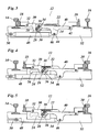
- Fig. 3 the state is shown in which the bearing block 34 has been pivoted so far that the locking pin 28 is released from the locking seat 26 and lies in the guide slot 24.
- the exact contour of the locking seat 26 is therefore in Fig. 3 to recognize more clearly.
- the remote switch tongue 20 and the connecting member 40 have slightly to the right in Fig. 3 relocated.
- the link has been slightly pivoted about the hinge 42 because the bearing pin 38 has lifted.
- the hinge 46, on which the spring 48 engages, has also shifted slightly to the right. Since the control rod 50 was not actuated when driving the switch, the spring 48 has been pulled out slightly.
- Fig. 4 shows the state at the end of the drive-up process.
- the switch tongue 20 now bears against the stock rail 16, while the switch tongue 18 has moved away from the stock rail 14.
- the guide pin 36 has moved to the right end of the guide slot 24.
- the locking pin 28 lies with its ends on the rectilinear upper edge of the guide slot 24 and has thus prevented further pivoting of the bearing block 34, so that the bearing block 34 has carried out a pure translational movement.
- the spring 48 is extended and thus is under considerable tension.
- the switch can due to the restoring force of the spring 48 back into the in Fig. 1 return home position shown.
- the locking pin 28 Towards the end of this movement, the locking pin 28 again falls on the locking seat 26, partly because of the dead weight of the locking lever 30, but mainly because of the force exerted by the bearing pin 28 on the bearing block 34 torque, which now acts in the counterclockwise direction.
- this shape of the locking lever 30 has the consequence that the locking pin 28 must move slightly to the right during the unlocking process.
- the contour of the locking seat 26 may be selected so that on the one hand this movement allows, on the other hand, however, ensures the self-locking when the force is applied via the locking lever 30 and the locking pin is not raised by the pivotal movement of the bearing block 34.
- Fig. 5 illustrates the case that the switch is not driven up, but with the help of acting on the control rod 50 (not shown) actuator is actively converted by the control rod 50 to the right in Fig. 5 is moved.
- the spring 48 is in This example is designed to be in the initial state according to Fig. 1 is on block so she can transmit shear forces.
- the force of the control rod 50 is then transmitted by the spring 48 on the hinge 46 and further via the connecting member 40 on the bearing pin 38.
- the unlocking can then be effected in the same way as above in connection with Fig. 1 and 3 has been described.
- the switch blade 20 is then moved by means of the control rod 50 and the spring 48 in the applied position.
- a second shutter may be provided for the switch blade 20 that is identical in construction to the shutter 12 described herein, but (except for the spring 48 and the control rod 50) is disposed in mirror image relation thereto.
- the springs 48 should then be designed so that they are in the in Fig. 1 and Fig. 5 state not shown to be block, but be in the neutral position from which they can both be stretched and compressed, so that a departure of the switch is possible even if the switch blade 20 is the adjacent tongue.
Landscapes
- Engineering & Computer Science (AREA)
- Mechanical Engineering (AREA)
- Architecture (AREA)
- Civil Engineering (AREA)
- Structural Engineering (AREA)
- Seats For Vehicles (AREA)
- Lock And Its Accessories (AREA)
- Train Traffic Observation, Control, And Security (AREA)
Claims (7)
- Dispositif de verrouillage pour des dispositifs d'aiguillage, ayant une pièce de verrouillage (22) qui forme une coulisse de guidage (24) s'étendant dans une direction de réglage de l'aiguille et un siège de blocage (26) s'étendant transversalement par rapport à la coulisse de guidage, un axe de guidage (36) mobile dans la coulisse de guidage (24), un axe d'articulation (38) relié à une lame d'aiguille décollée (20) et un support (34) qui peut pivoter autour de l'axe de l'axe de guidage (36) et dans lequel l'axe de guidage (36) et le bouton articulé (38) sont supportés, caractérisé en ce qu'un levier de blocage (30) relié de manière articulée à une lame d'aiguille collée (18) porte, sur l'extrémité éloignée de la lame d'aiguille (18), un axe d'arrêt (28) blocable sur le siège de blocage (26), l'axe d'arrêt (28), l'axe de guidage (36) et l'axe d'articulation (38) sont montés dans le support (34) dans une configuration triangulaire de telle sorte que l'axe d'arrêt (28) et l'axe articulé (38) sont positionnés sur des côtés opposés de la coulisse de guidage (24) et sont plus proches de la lame d'aiguille collée (18) que l'axe de guidage (36), et en ce qu'un ressort (48) précontraint la lame d'aiguille (20) en direction de sa position décollée.
- Dispositif de verrouillage selon la revendication 1, dans lequel une articulation (32) relie le levier de verrouillage (30) à la lame d'aiguille collée (18), et l'axe d'arrêt (28) est positionné sur des côtés opposés de l'axe central de la coulisse de guidage (24).
- Dispositif de verrouillage selon l'une des revendications précédentes, le dispositif de verrouillage ayant une construction symétrique par rapport au levier de verrouillage (30), les coulisses de guidage (24) étant agencées des deux côtés dudit levier de verrouillage (30).
- Dispositif de verrouillage selon la revendication 3, dans lequel le support (34) et l'axe de guidage (36) sont respectivement formés par deux pièces situées des deux côtés du plan de symétrie.
- Dispositif de verrouillage selon l'une des revendications précédentes, dans lequel l'axe d'articulation (38) est relié à la lame d'aiguille décollée (20) par un élément de liaison (40) sur lequel agit le ressort (48).
- Dispositif de verrouillage selon la revendication 5, dans lequel le ressort (48) est agencé dans un plan décalé par rapport à la coulisse de guidage (24) et agit sur une patte (44) faisant saillie pratiquement au centre de l'élément de liaison (40).
- Dispositif de verrouillage selon l'une des revendications précédentes, dans lequel le ressort (48) peut être allongé d'une quantité qui correspond à la course de déplacement des lames d'aiguille (18, 20).
Priority Applications (1)
| Application Number | Priority Date | Filing Date | Title |
|---|---|---|---|
| PL11725887T PL2576314T3 (pl) | 2010-05-28 | 2011-05-27 | Zamknięcie dla nastawczego napędu zwrotnicowego |
Applications Claiming Priority (2)
| Application Number | Priority Date | Filing Date | Title |
|---|---|---|---|
| DE202010005519U DE202010005519U1 (de) | 2010-05-28 | 2010-05-28 | Verschluss für Weichenstellvorrichtungen |
| PCT/EP2011/058723 WO2011147961A1 (fr) | 2010-05-28 | 2011-05-27 | Dispositif de blocage pour systèmes de manoeuvre d'aiguille |
Publications (2)
| Publication Number | Publication Date |
|---|---|
| EP2576314A1 EP2576314A1 (fr) | 2013-04-10 |
| EP2576314B1 true EP2576314B1 (fr) | 2014-03-19 |
Family
ID=44543992
Family Applications (1)
| Application Number | Title | Priority Date | Filing Date |
|---|---|---|---|
| EP11725887.1A Not-in-force EP2576314B1 (fr) | 2010-05-28 | 2011-05-27 | Dispositif de blocage pour systèmes de manoeuvre d'aiguille |
Country Status (12)
| Country | Link |
|---|---|
| US (1) | US20130068896A1 (fr) |
| EP (1) | EP2576314B1 (fr) |
| CN (1) | CN103003129A (fr) |
| AU (1) | AU2011257172B2 (fr) |
| BR (1) | BR112012030283A2 (fr) |
| CL (1) | CL2012003297A1 (fr) |
| DE (1) | DE202010005519U1 (fr) |
| ES (1) | ES2460068T3 (fr) |
| PL (1) | PL2576314T3 (fr) |
| PT (1) | PT2576314E (fr) |
| WO (1) | WO2011147961A1 (fr) |
| ZA (1) | ZA201208879B (fr) |
Families Citing this family (6)
| Publication number | Priority date | Publication date | Assignee | Title |
|---|---|---|---|---|
| US8684318B2 (en) * | 2010-09-16 | 2014-04-01 | Spx International Limited | Mechanical lock |
| CN108842534B (zh) * | 2018-08-16 | 2023-07-28 | 西南交通大学 | 一种用于空轨道岔的大扭矩弹性可变约束铰 |
| DE102020212273A1 (de) * | 2020-09-29 | 2022-03-31 | Siemens Mobility GmbH | Sperrvorrichtung und Sperrverfahren für einen Weichenantrieb sowie Weichenantrieb |
| CN112719998B (zh) * | 2020-12-24 | 2022-04-22 | 广东普拉迪科技股份有限公司 | 一种可自由移动的夹具 |
| JP7737331B2 (ja) * | 2022-03-16 | 2025-09-10 | 大同信号株式会社 | 電気転てつ機のロック状態検知装置 |
| DE102022203037A1 (de) * | 2022-03-28 | 2023-09-28 | Siemens Mobility GmbH | Weiche mit Auffahrmechanismus |
Family Cites Families (8)
| Publication number | Priority date | Publication date | Assignee | Title |
|---|---|---|---|---|
| SE397696B (sv) * | 1976-04-22 | 1977-11-14 | Personer Sparteknik Ab | Anordning vid sparvexel |
| DE29709420U1 (de) | 1997-05-30 | 1998-10-01 | Hanning & Kahl GmbH & Co., 33813 Oerlinghausen | Vorrichtung zum Verriegeln von beweglichen Weichenteilen |
| DE10000804A1 (de) * | 2000-01-11 | 2001-07-26 | Schreck Mieves Gmbh | Weichenverschluß für Weichenzungen |
| AT411047B (de) * | 2001-01-11 | 2003-09-25 | Vae Eisenbahnsysteme Gmbh | Einrichtung zum verriegeln der endlagen von beweglichen weichenteilen |
| ITSV20030006A1 (it) * | 2003-02-18 | 2004-08-19 | Alstom Transp Spa | Cassa di manovra per deviatori ferroviari tramviari o simili. |
| ITFI20030296A1 (it) * | 2003-11-19 | 2005-05-20 | Ge Transp Systems S P A | Cassa di manovra per scambi ferroviari |
| FR2905922B1 (fr) * | 2006-09-14 | 2008-12-05 | Vossloh Cogifer Sa | Mecanisme de manoeuvre d'aiguilles |
| CN201385684Y (zh) * | 2009-05-22 | 2010-01-20 | 新铁德奥道岔有限公司 | 道岔基尖轨锁闭装置 |
-
2010
- 2010-05-28 DE DE202010005519U patent/DE202010005519U1/de not_active Expired - Lifetime
-
2011
- 2011-05-27 AU AU2011257172A patent/AU2011257172B2/en not_active Ceased
- 2011-05-27 US US13/699,821 patent/US20130068896A1/en not_active Abandoned
- 2011-05-27 PL PL11725887T patent/PL2576314T3/pl unknown
- 2011-05-27 ES ES11725887.1T patent/ES2460068T3/es active Active
- 2011-05-27 EP EP11725887.1A patent/EP2576314B1/fr not_active Not-in-force
- 2011-05-27 BR BR112012030283A patent/BR112012030283A2/pt not_active IP Right Cessation
- 2011-05-27 WO PCT/EP2011/058723 patent/WO2011147961A1/fr not_active Ceased
- 2011-05-27 PT PT117258871T patent/PT2576314E/pt unknown
- 2011-05-27 CN CN2011800272829A patent/CN103003129A/zh active Pending
-
2012
- 2012-11-26 CL CL2012003297A patent/CL2012003297A1/es unknown
- 2012-11-26 ZA ZA2012/08879A patent/ZA201208879B/en unknown
Also Published As
| Publication number | Publication date |
|---|---|
| DE202010005519U1 (de) | 2011-10-05 |
| BR112012030283A2 (pt) | 2016-08-09 |
| ES2460068T3 (es) | 2014-05-13 |
| WO2011147961A1 (fr) | 2011-12-01 |
| AU2011257172B2 (en) | 2014-06-19 |
| US20130068896A1 (en) | 2013-03-21 |
| PL2576314T3 (pl) | 2014-08-29 |
| AU2011257172A1 (en) | 2012-12-20 |
| ZA201208879B (en) | 2013-07-31 |
| CN103003129A (zh) | 2013-03-27 |
| EP2576314A1 (fr) | 2013-04-10 |
| PT2576314E (pt) | 2014-04-30 |
| CL2012003297A1 (es) | 2013-12-06 |
Similar Documents
| Publication | Publication Date | Title |
|---|---|---|
| EP1497217B1 (fr) | Systeme pour actionner et verrouiller des portes d'ascenseur au moyen de barres d'entrainement | |
| EP0222160B1 (fr) | Mécanisme d'actionnement pour une porte de chargement de fret | |
| DE69813275T2 (de) | Schaltkasten für eisenbahn, strassenbahnweichen oder dergleichen vom sogenannten englischen typ | |
| EP2576314B1 (fr) | Dispositif de blocage pour systèmes de manoeuvre d'aiguille | |
| DE102011087174B4 (de) | Fahrzeugsitz | |
| WO2009156256A2 (fr) | Système de porte d'ascenseur à dispositif de verrouillage de porte de cabine | |
| EP2216204B1 (fr) | Galerie pour véhicules automobiles | |
| DE3020788C2 (de) | Innenverschlußeinrichtung für einen Weichenantrieb | |
| DE102004049969B3 (de) | Modulare Scherenbrücke sowie Verlegeeinrichtung und Verfahren zum Verlegen zerlegbarer Brücken | |
| DE3905445A1 (de) | Vorderbacken fuer sicherheitsskibindungen | |
| EP3159452B1 (fr) | Chargeur frontal | |
| EP3861240B1 (fr) | Dispositif de recouvrement pour une armoire de machine | |
| DE102009016399B4 (de) | Öffnungsvorrichtung für Schwenkschiebetüren | |
| AT521511B1 (de) | Selbsteinziehvorrichtung | |
| DE102006004531B3 (de) | Rückenlehne für einen Fahrzeugsitz | |
| DE1905074C2 (de) | Verschlußvorrichtung | |
| EP4339062A1 (fr) | Procédé de centrage ou de déviation, de préférence d'une tête d'attelage d'un véhicule ferroviaire, et dispositif de support pour la mise en oeuvre du procédé | |
| EP1048513B2 (fr) | Dispositif de levier pour un dispositif de commande sur un siège de véhicule | |
| DE10018028C2 (de) | Ballastiervorrichtung | |
| DE102008064441B4 (de) | Fahrzeugsitzeinrichtung | |
| DE60318718T2 (de) | Betätigungsvorrichtung für ein öffnungsfähiges Fahrzeugdach | |
| EP1795677B1 (fr) | Agencement de capot d'un véhicule avec un dispositif de verrouillage | |
| EP1414689A1 (fr) | Verrouillage mobile pour parois coulissantes | |
| EP2995525B1 (fr) | Tete d'accouplement pour un vehicule sur rails | |
| DE102021134388A1 (de) | Mitnehmersystem |
Legal Events
| Date | Code | Title | Description |
|---|---|---|---|
| PUAI | Public reference made under article 153(3) epc to a published international application that has entered the european phase |
Free format text: ORIGINAL CODE: 0009012 |
|
| 17P | Request for examination filed |
Effective date: 20121120 |
|
| AK | Designated contracting states |
Kind code of ref document: A1 Designated state(s): AL AT BE BG CH CY CZ DE DK EE ES FI FR GB GR HR HU IE IS IT LI LT LU LV MC MK MT NL NO PL PT RO RS SE SI SK SM TR |
|
| DAX | Request for extension of the european patent (deleted) | ||
| GRAP | Despatch of communication of intention to grant a patent |
Free format text: ORIGINAL CODE: EPIDOSNIGR1 |
|
| INTG | Intention to grant announced |
Effective date: 20131002 |
|
| GRAS | Grant fee paid |
Free format text: ORIGINAL CODE: EPIDOSNIGR3 |
|
| GRAA | (expected) grant |
Free format text: ORIGINAL CODE: 0009210 |
|
| AK | Designated contracting states |
Kind code of ref document: B1 Designated state(s): AL AT BE BG CH CY CZ DE DK EE ES FI FR GB GR HR HU IE IS IT LI LT LU LV MC MK MT NL NO PL PT RO RS SE SI SK SM TR |
|
| REG | Reference to a national code |
Ref country code: GB Ref legal event code: FG4D Free format text: NOT ENGLISH |
|
| REG | Reference to a national code |
Ref country code: CH Ref legal event code: EP |
|
| REG | Reference to a national code |
Ref country code: AT Ref legal event code: REF Ref document number: 657469 Country of ref document: AT Kind code of ref document: T Effective date: 20140415 |
|
| REG | Reference to a national code |
Ref country code: IE Ref legal event code: FG4D Free format text: LANGUAGE OF EP DOCUMENT: GERMAN |
|
| REG | Reference to a national code |
Ref country code: SE Ref legal event code: TRGR |
|
| REG | Reference to a national code |
Ref country code: PT Ref legal event code: SC4A Free format text: AVAILABILITY OF NATIONAL TRANSLATION Effective date: 20140421 |
|
| REG | Reference to a national code |
Ref country code: NL Ref legal event code: T3 |
|
| REG | Reference to a national code |
Ref country code: DE Ref legal event code: R096 Ref document number: 502011002485 Country of ref document: DE Effective date: 20140508 |
|
| REG | Reference to a national code |
Ref country code: ES Ref legal event code: FG2A Ref document number: 2460068 Country of ref document: ES Kind code of ref document: T3 Effective date: 20140513 |
|
| REG | Reference to a national code |
Ref country code: NO Ref legal event code: T2 Effective date: 20140319 |
|
| PG25 | Lapsed in a contracting state [announced via postgrant information from national office to epo] |
Ref country code: LT Free format text: LAPSE BECAUSE OF FAILURE TO SUBMIT A TRANSLATION OF THE DESCRIPTION OR TO PAY THE FEE WITHIN THE PRESCRIBED TIME-LIMIT Effective date: 20140319 |
|
| PGFP | Annual fee paid to national office [announced via postgrant information from national office to epo] |
Ref country code: IE Payment date: 20140514 Year of fee payment: 4 |
|
| REG | Reference to a national code |
Ref country code: GR Ref legal event code: EP Ref document number: 20140400856 Country of ref document: GR Effective date: 20140625 |
|
| REG | Reference to a national code |
Ref country code: LT Ref legal event code: MG4D |
|
| PG25 | Lapsed in a contracting state [announced via postgrant information from national office to epo] |
Ref country code: CY Free format text: LAPSE BECAUSE OF FAILURE TO SUBMIT A TRANSLATION OF THE DESCRIPTION OR TO PAY THE FEE WITHIN THE PRESCRIBED TIME-LIMIT Effective date: 20140319 |
|
| PGFP | Annual fee paid to national office [announced via postgrant information from national office to epo] |
Ref country code: NO Payment date: 20140513 Year of fee payment: 4 Ref country code: FR Payment date: 20140530 Year of fee payment: 4 Ref country code: ES Payment date: 20140522 Year of fee payment: 4 Ref country code: SE Payment date: 20140519 Year of fee payment: 4 Ref country code: DE Payment date: 20140521 Year of fee payment: 4 Ref country code: IT Payment date: 20140531 Year of fee payment: 4 Ref country code: CZ Payment date: 20140519 Year of fee payment: 4 Ref country code: PT Payment date: 20140516 Year of fee payment: 4 Ref country code: FI Payment date: 20140516 Year of fee payment: 4 Ref country code: NL Payment date: 20140521 Year of fee payment: 4 Ref country code: RO Payment date: 20140519 Year of fee payment: 4 Ref country code: GR Payment date: 20140514 Year of fee payment: 4 |
|
| REG | Reference to a national code |
Ref country code: PL Ref legal event code: T3 |
|
| PG25 | Lapsed in a contracting state [announced via postgrant information from national office to epo] |
Ref country code: HR Free format text: LAPSE BECAUSE OF FAILURE TO SUBMIT A TRANSLATION OF THE DESCRIPTION OR TO PAY THE FEE WITHIN THE PRESCRIBED TIME-LIMIT Effective date: 20140319 Ref country code: RS Free format text: LAPSE BECAUSE OF FAILURE TO SUBMIT A TRANSLATION OF THE DESCRIPTION OR TO PAY THE FEE WITHIN THE PRESCRIBED TIME-LIMIT Effective date: 20140319 |
|
| PGFP | Annual fee paid to national office [announced via postgrant information from national office to epo] |
Ref country code: BE Payment date: 20140530 Year of fee payment: 4 Ref country code: LV Payment date: 20140523 Year of fee payment: 4 |
|
| PG25 | Lapsed in a contracting state [announced via postgrant information from national office to epo] |
Ref country code: BG Free format text: LAPSE BECAUSE OF FAILURE TO SUBMIT A TRANSLATION OF THE DESCRIPTION OR TO PAY THE FEE WITHIN THE PRESCRIBED TIME-LIMIT Effective date: 20140619 Ref country code: IS Free format text: LAPSE BECAUSE OF FAILURE TO SUBMIT A TRANSLATION OF THE DESCRIPTION OR TO PAY THE FEE WITHIN THE PRESCRIBED TIME-LIMIT Effective date: 20140719 Ref country code: EE Free format text: LAPSE BECAUSE OF FAILURE TO SUBMIT A TRANSLATION OF THE DESCRIPTION OR TO PAY THE FEE WITHIN THE PRESCRIBED TIME-LIMIT Effective date: 20140319 |
|
| PG25 | Lapsed in a contracting state [announced via postgrant information from national office to epo] |
Ref country code: SK Free format text: LAPSE BECAUSE OF FAILURE TO SUBMIT A TRANSLATION OF THE DESCRIPTION OR TO PAY THE FEE WITHIN THE PRESCRIBED TIME-LIMIT Effective date: 20140319 |
|
| PGFP | Annual fee paid to national office [announced via postgrant information from national office to epo] |
Ref country code: PL Payment date: 20140513 Year of fee payment: 4 |
|
| REG | Reference to a national code |
Ref country code: DE Ref legal event code: R097 Ref document number: 502011002485 Country of ref document: DE |
|
| PG25 | Lapsed in a contracting state [announced via postgrant information from national office to epo] |
Ref country code: LU Free format text: LAPSE BECAUSE OF FAILURE TO SUBMIT A TRANSLATION OF THE DESCRIPTION OR TO PAY THE FEE WITHIN THE PRESCRIBED TIME-LIMIT Effective date: 20140527 |
|
| REG | Reference to a national code |
Ref country code: CH Ref legal event code: PL |
|
| PLBE | No opposition filed within time limit |
Free format text: ORIGINAL CODE: 0009261 |
|
| STAA | Information on the status of an ep patent application or granted ep patent |
Free format text: STATUS: NO OPPOSITION FILED WITHIN TIME LIMIT |
|
| PG25 | Lapsed in a contracting state [announced via postgrant information from national office to epo] |
Ref country code: DK Free format text: LAPSE BECAUSE OF FAILURE TO SUBMIT A TRANSLATION OF THE DESCRIPTION OR TO PAY THE FEE WITHIN THE PRESCRIBED TIME-LIMIT Effective date: 20140319 Ref country code: MC Free format text: LAPSE BECAUSE OF FAILURE TO SUBMIT A TRANSLATION OF THE DESCRIPTION OR TO PAY THE FEE WITHIN THE PRESCRIBED TIME-LIMIT Effective date: 20140319 Ref country code: LI Free format text: LAPSE BECAUSE OF NON-PAYMENT OF DUE FEES Effective date: 20140531 Ref country code: CH Free format text: LAPSE BECAUSE OF NON-PAYMENT OF DUE FEES Effective date: 20140531 |
|
| 26N | No opposition filed |
Effective date: 20141222 |
|
| REG | Reference to a national code |
Ref country code: DE Ref legal event code: R097 Ref document number: 502011002485 Country of ref document: DE Effective date: 20141222 |
|
| PGFP | Annual fee paid to national office [announced via postgrant information from national office to epo] |
Ref country code: HU Payment date: 20140729 Year of fee payment: 4 |
|
| REG | Reference to a national code |
Ref country code: HU Ref legal event code: AG4A Ref document number: E022762 Country of ref document: HU |
|
| PG25 | Lapsed in a contracting state [announced via postgrant information from national office to epo] |
Ref country code: SI Free format text: LAPSE BECAUSE OF FAILURE TO SUBMIT A TRANSLATION OF THE DESCRIPTION OR TO PAY THE FEE WITHIN THE PRESCRIBED TIME-LIMIT Effective date: 20140319 |
|
| REG | Reference to a national code |
Ref country code: DE Ref legal event code: R119 Ref document number: 502011002485 Country of ref document: DE |
|
| REG | Reference to a national code |
Ref country code: PT Ref legal event code: MM4A Free format text: LAPSE DUE TO NON-PAYMENT OF FEES Effective date: 20151127 |
|
| REG | Reference to a national code |
Ref country code: NO Ref legal event code: MMEP |
|
| GBPC | Gb: european patent ceased through non-payment of renewal fee |
Effective date: 20150527 |
|
| PG25 | Lapsed in a contracting state [announced via postgrant information from national office to epo] |
Ref country code: FI Free format text: LAPSE BECAUSE OF NON-PAYMENT OF DUE FEES Effective date: 20150527 Ref country code: GR Free format text: LAPSE BECAUSE OF NON-PAYMENT OF DUE FEES Effective date: 20151208 Ref country code: IT Free format text: LAPSE BECAUSE OF NON-PAYMENT OF DUE FEES Effective date: 20150527 Ref country code: LV Free format text: LAPSE BECAUSE OF NON-PAYMENT OF DUE FEES Effective date: 20150527 Ref country code: NO Free format text: LAPSE BECAUSE OF NON-PAYMENT OF DUE FEES Effective date: 20150531 |
|
| REG | Reference to a national code |
Ref country code: NL Ref legal event code: MM Effective date: 20150601 |
|
| REG | Reference to a national code |
Ref country code: IE Ref legal event code: MM4A |
|
| REG | Reference to a national code |
Ref country code: FR Ref legal event code: ST Effective date: 20160129 |
|
| PG25 | Lapsed in a contracting state [announced via postgrant information from national office to epo] |
Ref country code: HU Free format text: LAPSE BECAUSE OF NON-PAYMENT OF DUE FEES Effective date: 20150528 Ref country code: PT Free format text: LAPSE BECAUSE OF NON-PAYMENT OF DUE FEES Effective date: 20151127 Ref country code: CZ Free format text: LAPSE BECAUSE OF NON-PAYMENT OF DUE FEES Effective date: 20150527 Ref country code: RO Free format text: LAPSE BECAUSE OF NON-PAYMENT OF DUE FEES Effective date: 20150527 Ref country code: SE Free format text: LAPSE BECAUSE OF NON-PAYMENT OF DUE FEES Effective date: 20150528 |
|
| REG | Reference to a national code |
Ref country code: GR Ref legal event code: ML Ref document number: 20140400856 Country of ref document: GR Effective date: 20151208 |
|
| PG25 | Lapsed in a contracting state [announced via postgrant information from national office to epo] |
Ref country code: MT Free format text: LAPSE BECAUSE OF FAILURE TO SUBMIT A TRANSLATION OF THE DESCRIPTION OR TO PAY THE FEE WITHIN THE PRESCRIBED TIME-LIMIT Effective date: 20140319 |
|
| PG25 | Lapsed in a contracting state [announced via postgrant information from national office to epo] |
Ref country code: GB Free format text: LAPSE BECAUSE OF NON-PAYMENT OF DUE FEES Effective date: 20150527 Ref country code: DE Free format text: LAPSE BECAUSE OF NON-PAYMENT OF DUE FEES Effective date: 20151201 Ref country code: IE Free format text: LAPSE BECAUSE OF NON-PAYMENT OF DUE FEES Effective date: 20150527 Ref country code: NL Free format text: LAPSE BECAUSE OF NON-PAYMENT OF DUE FEES Effective date: 20150601 Ref country code: SM Free format text: LAPSE BECAUSE OF FAILURE TO SUBMIT A TRANSLATION OF THE DESCRIPTION OR TO PAY THE FEE WITHIN THE PRESCRIBED TIME-LIMIT Effective date: 20140319 |
|
| PG25 | Lapsed in a contracting state [announced via postgrant information from national office to epo] |
Ref country code: FR Free format text: LAPSE BECAUSE OF NON-PAYMENT OF DUE FEES Effective date: 20150601 |
|
| PG25 | Lapsed in a contracting state [announced via postgrant information from national office to epo] |
Ref country code: TR Free format text: LAPSE BECAUSE OF FAILURE TO SUBMIT A TRANSLATION OF THE DESCRIPTION OR TO PAY THE FEE WITHIN THE PRESCRIBED TIME-LIMIT Effective date: 20140319 |
|
| PG25 | Lapsed in a contracting state [announced via postgrant information from national office to epo] |
Ref country code: PL Free format text: LAPSE BECAUSE OF NON-PAYMENT OF DUE FEES Effective date: 20150527 |
|
| REG | Reference to a national code |
Ref country code: ES Ref legal event code: FD2A Effective date: 20161125 |
|
| PG25 | Lapsed in a contracting state [announced via postgrant information from national office to epo] |
Ref country code: ES Free format text: LAPSE BECAUSE OF NON-PAYMENT OF DUE FEES Effective date: 20150528 |
|
| REG | Reference to a national code |
Ref country code: AT Ref legal event code: MM01 Ref document number: 657469 Country of ref document: AT Kind code of ref document: T Effective date: 20160527 |
|
| PG25 | Lapsed in a contracting state [announced via postgrant information from national office to epo] |
Ref country code: BE Free format text: LAPSE BECAUSE OF NON-PAYMENT OF DUE FEES Effective date: 20150531 |
|
| PG25 | Lapsed in a contracting state [announced via postgrant information from national office to epo] |
Ref country code: AT Free format text: LAPSE BECAUSE OF NON-PAYMENT OF DUE FEES Effective date: 20160527 |
|
| PG25 | Lapsed in a contracting state [announced via postgrant information from national office to epo] |
Ref country code: MK Free format text: LAPSE BECAUSE OF FAILURE TO SUBMIT A TRANSLATION OF THE DESCRIPTION OR TO PAY THE FEE WITHIN THE PRESCRIBED TIME-LIMIT Effective date: 20140319 |
|
| PG25 | Lapsed in a contracting state [announced via postgrant information from national office to epo] |
Ref country code: AL Free format text: LAPSE BECAUSE OF FAILURE TO SUBMIT A TRANSLATION OF THE DESCRIPTION OR TO PAY THE FEE WITHIN THE PRESCRIBED TIME-LIMIT Effective date: 20140319 |