EP2576417B1 - Magnetkappenausstosser im verschliesser - Google Patents
Magnetkappenausstosser im verschliesser Download PDFInfo
- Publication number
- EP2576417B1 EP2576417B1 EP11711465.2A EP11711465A EP2576417B1 EP 2576417 B1 EP2576417 B1 EP 2576417B1 EP 11711465 A EP11711465 A EP 11711465A EP 2576417 B1 EP2576417 B1 EP 2576417B1
- Authority
- EP
- European Patent Office
- Prior art keywords
- permanent magnet
- housing
- head
- ejector
- guide
- Prior art date
- Legal status (The legal status is an assumption and is not a legal conclusion. Google has not performed a legal analysis and makes no representation as to the accuracy of the status listed.)
- Active
Links
Images


Classifications
-
- B—PERFORMING OPERATIONS; TRANSPORTING
- B67—OPENING, CLOSING OR CLEANING BOTTLES, JARS OR SIMILAR CONTAINERS; LIQUID HANDLING
- B67B—APPLYING CLOSURE MEMBERS TO BOTTLES JARS, OR SIMILAR CONTAINERS; OPENING CLOSED CONTAINERS
- B67B3/00—Closing bottles, jars or similar containers by applying caps
- B67B3/26—Applications of control, warning, or safety devices in capping machinery
- B67B3/268—Applications of control, warning, or safety devices in capping machinery devices for avoiding damage to the closing machine
-
- B—PERFORMING OPERATIONS; TRANSPORTING
- B67—OPENING, CLOSING OR CLEANING BOTTLES, JARS OR SIMILAR CONTAINERS; LIQUID HANDLING
- B67B—APPLYING CLOSURE MEMBERS TO BOTTLES JARS, OR SIMILAR CONTAINERS; OPENING CLOSED CONTAINERS
- B67B3/00—Closing bottles, jars or similar containers by applying caps
- B67B3/20—Closing bottles, jars or similar containers by applying caps by applying and rotating preformed threaded caps
- B67B3/2066—Details of capping heads
Definitions
- the invention relates to a device for closing containers with closure or screw caps according to the preamble of claim 1, which has an ejector having an operative element, which returns an ejection element from an ejection position to an initial position.
- the DE 202 18 523 U1 discloses a device according to the preamble of claim 1 for closing containers, namely bottles with closure or screw caps, for example with internal thread, so that the screw caps are screwed onto the bottle.
- containers namely bottles with closure or screw caps, for example with internal thread
- To close the upright bottles are handed over by a conveyor via a bottle inlet of the device forming inlet star in each case successively to one of the closing positions.
- the sealed containers or bottles are removed via a discharge star the Versch conferencepositionen and discharged through a feed dog.
- each container or each bottle and thus each bottle holder performs with rotating rotor from a controlled vertical lifting movement so that each screw head received at a transfer position in each case a screw cap, then the mouth of the bottle is moved against the screw cap, and there by turning a Spindle is screwed around the spindle axis and tightened with a predetermined torque.
- the transfer position is provided in the direction of rotation of the rotor between the outlet star and the inlet star. The transfer position, the screw or caps are fed via a feed from a magazine in the required orientation and preferably in one-lane series close together.
- a height-adjustable support rod ejector is provided for the unused or stuck screw or cap.
- the ejector itself is mounted vertically movable on a screw shaft, and can against the force of an active element, which in the DE 202 18 523 U1 is designed as a spring, by an ejector rod, which is appropriately height-adjustable together with the bottle holder, are driven down to remove the screw, so that a Auswerferfinger acts against the screw or cap and this removes the unused screw or cap removed ,
- the ejector is against the force of the active element, that is, due to spring force from the ejection position is returned to the starting position.
- DE 102 55 196 A1 discloses a device for closing vessels, which also has an ejector with a designed as a spring active element.
- the DE 10 2006 035 279 A1 and the DE 100 56 990 A1 each describe a capping machine, wherein the problem of unused or stuck closure or screw caps is not discussed in each case.
- the sealing machines disclosed in the cited prior art have proven themselves in practice.
- the design of the ejector with its mechanical active element can be improved.
- the acting as a spring active element is subject to considerable wear, so that with increasing operating time spring damage can occur.
- an exchange of the active element or the spring is extremely complicated and time-consuming not only from the confined space conditions, but also due to the complicated structure of the entire system, which must be executed with his individual components adapted to the other component and mounted.
- soiling can settle especially in interstices or in niches in the spring area.
- in beverage technology plants so germs can occur that significantly affect the quality of the filled in the bottles or containers in the goods, if not even completely inedible or unusable, so that a considerable committee could arise.
- the invention is therefore an object of the invention to improve a device for closing containers with closure or screw caps, in particular their ejector with simple means so that the ejection element from its Austossposition be returned to its original position while avoiding the aforementioned disadvantages.
- the object is achieved by a device for closing containers with closure or screw caps having the features of claim 1, wherein the active element is designed as a magnetic element.
- the active element has a permanent magnet, which is arranged in a housing relatively movable to this, wherein at least one disposed in the axial direction arranged wall portion of the housing is magnetizable.
- the active element is formed from the permanent magnet in cooperation with the magnetizable wall portion of the housing. It is essential that while avoiding a mechanically acting active element to retrieve the ejection element act in its initial position magnetic forces.
- the permanent magnet is designed as a diametrically magnetized bar magnet, so designed as seen in cross-section round bar magnet whose magnetization passes through the diameter, with the north and south poles are opposite as half shells.
- the active element or its permanent magnet is arranged in a sleeve which has at its two ends, that is to say on its head side and its opposite foot side, a closure element, for example in the embodiment as a cap.
- the closure elements can be connected to the connection to the sleeve to this cohesively.
- Conceivable is an adhesive bond or a welded joint.
- the sleeve and caps may be formed of a plastic, and completely enclose the permanent magnet so that the permanent magnet is completely hermetically sealed from the environment when completely enclosed.
- the permanent magnet can be inserted with its head-side end or with its head-side cap in the housing.
- the housing is open at the foot.
- the housing in a favorable embodiment has a threaded portion for connection to a capper head.
- At the threaded portion of the magnetizable wall portion of the housing connects, which merges into a head part.
- the housing has a through-hole, which has a guide portion, a guide portion and an actuating portion.
- the guide section extends from the foot-side opening in the direction of the head part and merges into the guide section, which has a reduced clear diameter with respect to the guide section.
- At the guide portion of the actuating portion connects, which initially with a running out tapered transition region merges into a cylindrically executed area.
- a plunger In the cylindrical portion engages a plunger, which is in communication with a force introduction element, which is guided in a slotted guide on the head side of the housing.
- a force introduction element For example, an ejector control rod acts in a known manner on the force introduction element. It is useful if the plunger is adapted with its outer diameter to the head side arranged cylindrical portion of the through hole, wherein the outer diameter may be dimensioned slightly smaller than the clear diameter of the cylindrical portion.
- the permanent magnet is accommodated in the housing in such a way that, in its starting position, it protrudes from the housing on the foot side, and slightly engages in the guide section on the head side.
- the permanent magnet covered by the sleeve is designed with a smaller outside diameter than the respective clear diameter of both the guide section and the guide section.
- the Austosselement is connected to the foot-side cap of the permanent magnet in conjunction, in which a favorable manner a receiving bore for receiving a corresponding receiving portion of the ejection element is arranged.
- the plunger causes a longitudinal movement of the permanent magnet received in the sleeve relative to the housing preferably relative to the guide portion, and at the same time relative to the magnetizable wall portion of the housing and is thereby partially from moved out of the housing.
- the permanent magnet is moved out with its head end from the guide section.
- An axial displacement, ie the transfer from the initial position in the direction of or to the ejection position of the ejection element is preferably adapted to a screw or cap height.
- the magnetizable wall portion extends favorably from the head part in the direction of the threaded portion or to the threaded portion and includes the guide portion, and a portion of the guide portion of the through hole.
- the Austosselement removed the unused or stuck screw or cap, the Austosselement is returned by the magnetic force which is caused by the magnetic element (permanent magnet / magnetizable wall portion), in the starting position.
- the magnetizable wall section consists of a magnet, preferably of a magnetizable material, more preferably of a magnetizable stainless steel, e.g. formed with the material number 1.4112.
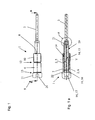
- FIG. 1 shows an ejector 1 of a device, not shown, for closing containers with closure or screw caps.
- a device for closing containers with closure or screw caps.
- Such devices are for example from the DE 202 18 523 U1 known, which will not be discussed further here and on supplies of closure or screw caps.
- unused or stuck closure or screw caps can be removed from a capping head, also not shown.
- the ejector 1 has an active element 2, which returns an ejection element 3 from an ejection position to an initial position, not shown.
- the active element 2 is advantageously designed as a magnetic (active) element 2, and has a permanent magnet 5 and a magnetizable wall portion 6 of a housing 7.
- the housing 7 has a foot side 8 and a head side 9 opposite thereto. From the foot 8, a threaded portion 10 extends in the direction of the head side 9. At the threaded portion 10, the magnetizable wall portion 6 connects, to which a head portion 11 connects.
- a groove 12 is arranged between the threaded portion 10 and the magnetizable wall portion 6 by way of example. Both sections 10 and 6 have, for example, approximately the same axial extension or length. Between the magnetizable wall portion 6 and the head part 11, a step 13 is arranged by way of example.
- a through-side open through hole 14 is arranged, which hineinerstreckt from the foot 8 in the head part 11.
- the through hole 14 is staged with a guide portion 15, a guide portion 16 and an actuating portion 17 executed as FIG. 1 a is to be taken.
- the guide section 15 extends from the foot 8 through the threaded portion 10 in the magnetizable wall portion 6 into and ends viewed in the longitudinal direction slightly in front of the head part 11. At the guide portion 15, the guide portion 16 connects, which with respect to the guide portion 15 a reduced clear Diameter, so that in the transition from the guide portion 15 to the guide portion 16, a step is formed ( FIG. 2 ).
- the guide section 16 has, relative to the guide section 15, a smaller axial length, which of course should only be by way of example.
- the guide section 16 extends by way of example only through the magnetizable wall section 6 ends at the transition to the head part 11 (FIG. FIG. 2 ).
- the actuating portion 17 extends through the head part 11 and has two areas 18 and 19.
- a transition region 18 adjoins the guide section 16 and is conically tapered.
- a cylindrical region 19 connects.
- the permanent magnet 5 is exemplified as a diametrically magnetized bar magnet.
- the two poles are in the FIGS. 1 a and 4 marked with N and S.
- the permanent magnet 5 is comprised by a sleeve 20, on which closure elements 21 and 22 in the exemplary embodiment as the foot cap 21 and as the head cap 22 are arranged on both the head side and the foot side.
- the sleeve 20 and the caps 21 and 22 may be made of a plastic, and are connected together.
- a cohesive connection in the embodiment can be selected as an adhesive or welded connection.
- the plastic coating of the permanent magnet 5 may e.g. have a corrosion-protective function.
- the permanent magnet 5 has, together with the comprehensive sleeve 20 has an outer diameter which is smaller than the clear diameter of both the guide portion 15 and the guide portion 16. Exemplary is in FIG. 4 an annular gap 23 between the outer circumference of the shell 20 with the permanent magnet 5 disposed therein and the magnetizable wall portion 6 along the line Y, that is shown in the region of the guide portion 15.
- the head-side cap 22 is an unillustrated plunger in conjunction.
- the plunger is connected to a force introduction element, not shown, on which an ejector control rod, not shown, acts.
- the plunger extends through the actuating portion 17 in the direction of the head-side cap 22.
- the head-side cap 22 can be regarded as a kind of buffer element, which avoids direct contact of plunger and permanent magnet 5.
- the head-side cap 22 can also be considered as a guide element within the guide portion 16.
- an axial guide slot 24 is arranged, which guides the force introduction element in the longitudinal direction of the housing 7. Due to the selected view, only a lower portion of the guide slot 24 can be seen, wherein an upper portion is not shown. Opposite to the recognizable in the plane of the drawing guide slot 24 and the recognizable guide slot 24, a further guide slot is provided, which is also fully closed. The force introduction element and the plunger arranged thereon are thus positively guided on the housing 7 on diametrically opposite guide slots.
- the Austosselement 3 is arranged, which can be referred to as Austossfinger.
- the Austosselement 3 is held by way of example in an arranged in the foot-side cap 21 receiving bore 25 with a receiving portion 26 adapted thereto positionally secure. It is conceivable to arrange a thread on the receiving region 26 in order to produce a screw connection, it being possible for an abutment flange to be arranged on the receiving region, which can abut against an end face of the cap 21.
- the Austosselement 3 acts on the unused or stuck closure or screw cap so that it pushed out of the capper head, i. Will get removed.
- the permanent magnet 5 is received in the housing 7 and movable relative to this or movable.
- the housing 7 is connected with its threaded portion 10 with the capper head, through which the Austosselement 3 and the Austossfinger same axis passes.
- the plunger acts on the head-side cap 22, that the permanent magnet 5 is displaced along its longitudinal axis in the direction of the foot 8 relative to the magnetizable wall portion 6 of the housing 7, which also connected to the permanent magnet 5 Austosselement 3 is moved to the Austossposition shown in the figures.
- the invention can be dispensed with mechanical active elements, such as springs, which are subject to great wear and are prone to failure.
- mechanical active elements such as springs
- no feather fins are formed in which dirt can accumulate.
- sealing elements are arranged, which seal the annular gap 23.
Landscapes
- Engineering & Computer Science (AREA)
- Mechanical Engineering (AREA)
- Closures For Containers (AREA)
- Sealing Of Jars (AREA)
Description
- Die Erfindung betrifft eine Vorrichtung zum Verschließen von Behältern mit Verschluss- oder Schraubkappen gemäß dem Oberbegriff des Anspruchs 1, welche einen Ausstoßer aufweist, der ein Wirkelement hat, welches ein Ausstoßelement aus einer Ausstoßposition in eine Ausgangsposition zurückführt.
- Die
DE 202 18 523 U1 zum Beispiel offenbart eine Vorrichtung gemäß dem Oberbegriff des Anspruchs 1 zum Verschließen von Behältern, nämlich Flaschen mit Verschluß- bzw. Schraubkappen, z.B. mit Innengewinde, so dass die Schraubkappen auf die Flasche aufschraubbar sind. Zum verschließen werden die Aufrecht stehenden Flaschen von einem Transporteur über einen Flascheneinlauf der Vorrichtung bildenden Einlaufstern jeweils nacheinander an eine der Verschließpositionen übergeben. Die verschlossenen Behälter bzw. Flaschen werden über einen Auslaufstern den Verschließpositionen entnommen und über einen Transporteur abgeführt. Jeder Behälter bzw. jede Flasche und somit auch jeder Flaschenhalter führt bei umlaufenden Rotor eine gesteuerte vertikale Hubbewegung so aus, dass von jedem Schraubkopf an einer Übergabeposition jeweils eine Schraubkappe aufgenommen, anschließend die Mündung der Flasche gegen die Schraubkappe bewegt wird, und dort durch Drehen einer Spindel um deren Spindelachse aufgeschraubt und mit vorgegebenem Drehmoment festgedreht wird. Wie dieDE 202 18 523 U1 offenbart ist die Übergabeposition in Umlaufrichtung des Rotors zwischen dem Auslaufstern und dem Einlaufstern vorgesehen. Der Übergabeposition werden die Schraub- oder Verschlusskappen über eine Zuführung von einem Magazin in erforderlicher Orientierung und in bevorzugt einspuriger Reihe dicht aneinander anschließend zugeführt. In der Praxis hat sich gezeigt, dass nicht alle aufgenommenen Schraub- oder Verschlusskappen verwertet werden oder hängen bleiben, so dass ein an einer höhenbeweglichen Trägerstange angeordneter Ausstoßer für die nicht verwerteten oder hängen gebliebenen Schraub- oder Verschlusskappen vorgesehen ist. Der Ausstoßer selbst ist höhenbeweglich auf einer Schraubwelle gelagert, und kann gegen die Kraft eines Wirkelementes, welches in derDE 202 18 523 U1 als Feder ausgeführt ist, von einer Auswerferstange, welche zweckmäßig gemeinsam mit dem Flaschenhalter höhenbeweglich ist, nach unten zum Entfernen der Schraubkappe angesteuert werden, so dass ein Auswerferfinger gegen die Schraub- oder Verschlusskappe wirkt und diese entfernt Ist die nicht verwendete Schraub- oder Verschlusskappe entfernt, wird der Auswerferfinger entgegen der Kraft des Wirkelementes, also federkraftbedingt aus der Ausstoßposition in die Ausgangslage zurückgeführt wird. - Auch die
DE 102 55 196 A1 offenbart eine Vorrichtung zum Verschließen von Gefäßen, welche ebenfalls einen Ausstoßer mit einem als Feder ausgeführtes Wirkelement aufweist. - Die
DE 10 2006 035 279 A1 und dieDE 100 56 990 A1 beschreiben jeweils eine Verschließmaschine, wobei das Problem nicht verwendeter bzw. hängen gebliebener Verschluss- oder Schraubkappen jeweils nicht thematisiert wird. - Grundsätzlich haben sich die in dem zitierten Stand der Technik offenbarten Verschließmaschinen in der Praxis bewährt. Verbesserungswürdig ist jedoch die Ausgestaltung des Ausstossers mit seinem mechanischen Wirkelement. Beispielsweise unterliegt das als Feder ausgeführte Wirkelement einem erheblichen Verschleiß, so dass mit zunehmender Betriebsdauer ein Federschaden auftreten kann. Ein Austausch des Wirkelementes bzw. der Feder ist jedoch nicht nur aus den beengten Bauraumbedingungen heraus äußerst kompliziert und zeitaufwändig, sondern auch aufgrund des komplizierten Aufbaus des gesamten Systems, welches mit seinen einzelnen Komponenten auf die jeweils andere Komponente angepasst ausgeführt und montiert werden muss. Auch ist nachteilig, dass sich insbesondere in Zwischenräumen bzw. in Nischen im Federbereich Verschmutzungen absetzen können. Insbesondere bei getränketechnologischen Anlagen können so Keime entstehen, welche die Qualität des in den Flaschen bzw. in den Behältern eingefüllten Gutes erheblich beeinträchtigen, wenn nicht sogar vollständig ungenießbar bzw. unbrauchbar machen, so dass ein erheblicher Ausschuss entstehen könnte.
- Der Erfindung liegt daher die Aufgabe zugrunde, eine Vorrichtung zum Verschließen von Behältern mit Verschluss- oder Schraubkappen , insbesondere deren Ausstoßer mit einfachen Mitteln so zu verbessern, dass das Ausstoßelement aus seiner Austossposition in seine Ausgangslage unter Vermeidung vorgenannter Nachteile rückholbar ist.
- Erfindungsgemäß wird die Aufgabe durch eine Vorrichtung zum Verschließen von Behältern mit Verschluss- oder Schraubkappen mit den Merkmalen des Anspruchs 1 gelöst, wobei das Wirkelement als magnetisches Element ausgeführt ist.
- Zweckmäßig im Sinn der Erfindung ist, wenn das Wirkelement einen Dauermagnet aufweist, welcher in einem Gehäuse relativ beweglich zu diesem angeordnet ist, wobei zumindest ein in Axialrichtung gesehen angeordneter Wandabschnitt des Gehäuses magnetisierbar ist. Insofern ist vorteilhaft vorgesehen, dass das Wirkelement aus dem Dauermagneten in Zusammenwirken mit dem magnetisierbaren Wandabschnitt des Gehäuses gebildet wird. Wesentlich ist, dass unter Vermeidung eines mechanisch wirkenden Wirkelementes zum Zurückholen des Ausstoßelementes in seine Ausgangslage magnetische Kräfte wirken.
- Günstiger Weise ist der Dauermagnet als diametral magnetisierter Stabmagnet ausgeführt, also als im Querschnitt gesehen runder Stabmagnet ausgeführt, dessen Magnetisierung durch den Durchmesser verläuft, wobei sich der Nord- und Südpol als Halbschalen gegenüber liegen.
- Günstig ist, wenn das Wirkelement bzw. sein Dauermagnet in einer Hülse angeordnet ist, welche an ihren beiden Enden, also an ihrer Kopfseite und ihrer dazu gegenüberliegenden Fußseite ein Verschlusselement, zum Beispiel in der Ausgestaltung als Kappe aufweist. Die Verschlusselemente können zur Verbindung mit der Hülse an diese stoffschlüssig angebunden werden. Denkbar ist dabei eine Klebverbindung oder eine Schweißverbindung. Die Hülse und die Kappen können aus einem Kunststoff gebildet sein, und schließen den Dauermagneten vollständig ein, so dass der Dauermagnet vollständig umschlossen von der Umwelt hermetisch abgeriegelt ist.
- Der Dauermagnet kann so mit seinem kopfseitigen Ende bzw. mit seiner kopfseitigen Kappe in das Gehäuse eingeführt werden.
- In bevorzugter Ausgestaltung ist vorgesehen, dass das Gehäuse fußseitig geöffnet ist. An seinem Fußbereich weist das Gehäuse in günstiger Ausgestaltung einen Gewindeabschnitt zur Verbindung mit einem Verschließerkopf auf. An den Gewindeabschnitt schließt sich der magnetisierbare Wandabschnitt des Gehäuses an, welcher in ein Kopfteil übergeht. Das Gehäuse weist eine Durchgangsbohrung auf, die einen Leitabschnitt, einen Führungsabschnitt und einen Betätigungsabschnitt aufweist. Der Leitabschnitt erstreckt sich von der fußseitigen Öffnung in Richtung zum Kopfteil und geht in den Führungsabschnitt über, welcher bezogen auf den Leitabschnitt einen reduzierten lichten Durchmesser aufweist. An dem Führungsabschnitt schließt sich der Betätigungsabschnitt an, welcher zunächst mit einem sich konusförmig verjüngenden Übergangsbereich ausgeführt in einen zylindrisch ausgeführten Bereich übergeht. In den zylindrischen Bereich greift ein Stößel ein, welcher mit einem Krafteinleitungselement in Verbindung steht, welches in einer Kulissenführung an der Kopfseite des Gehäuses geführt ist. Auf das Krafteinleitungselement wirkt z.B. eine Auswerfersteuerstange in bekannter Weise ein. Zweckmäßig ist, wenn der Stößel mit seinem Außendurchmesser an den kopfseitig angeordneten zylindrischen Bereich der Durchgangsbohrung angepasst ist, wobei der Außendurchmesser etwas kleiner dimensioniert sein kann als der lichte Durchmesser des zylindrischen Bereiches.
- Der Dauermagnet ist so in dem Gehäuse aufgenommen, dass dieser in seiner Ausgangslage fußseitig aus dem Gehäuse herausragt, und kopfseitig etwas in den Führungsabschnitt eingreift. In Umfangsrichtung gesehen ist der mit der Hülse umfasste Dauermagnet mit einem geringeren Außendurchmesser ausgeführt als der jeweilige lichte Durchmesser sowohl des Leitabschnitts als auch des Führungsabschnitts.
- Das Austosselement steht mit der fußseitigen Kappe des Dauermagneten in Verbindung, in welcher günstiger Weise eine Aufnahmebohrung zur Aufnahme eines entsprechenden Aufnahmeabschnitts des Ausstosselementes angeordnet ist.
- Wird nun das Krafteinleitungselement über die Auswerfersteuerstange längs des Gehäuses in Richtung zur Fußseite bewegt, bewirkt der Stößel eine Längsbewegung des in der Hülse aufgenommenen Dauermagneten relativ zum Gehäuse bevorzugt relativ zu dessen Führungsabschnitt, und gleichzeitig relativ zu dem magnetisierbaren Wandabschnitt des Gehäuses und wird dabei bereichsweise aus dem Gehäuse herausbewegt. Dabei wird der Dauermagnet mit seinem kopfseitigen Ende aus dem Führungsabschnitt herausbewegt. Ein axialer Verschiebeweg, also die Überführung aus der Ausgangslage in Richtung zur oder bis zur Ausstoßposition des Ausstosselementes ist bevorzugt an eine Schraub- oder Verschlusskappenhöhe angepasst.
- Der magnetisierbare Wandabschnitt erstreckt sich dabei günstiger Weise von dem Kopfteil in Richtung zum Gewindeabschnitt bzw. bis zum Gewindeabschnitt und umfasst den Führungsabschnitt, sowie eine Teilbereich des Leitabschnitts der Durchgangsbohrung.
- Hat das Austosselement die nicht verwertete oder hängen gebliebene Schraub- oder Verschlusskappe entfernt, wird das Austosselement mittels der magnetischen Kraft, welche durch das magnetische Element (Dauermagnet/magnetisierbarer Wandabschnitt) bewirkt wird, in die Ausgangslage zurückgeführt.
- In zweckmäßiger weise ist vorgesehen, dass der magnetisierbare Wandabschnitt aus einem Magneten, bevorzugt aus einem magnetisierbaren Material, weiter bevorzugt aus einem magnetisierbaren Edelstahl z.B. mit der Werkstoffnummer 1.4112 gebildet ist.
- Weitere vorteilhafte Ausgestaltungen der Erfindung sind in den Unteransprüchen und der folgenden Figurenbeschreibung offenbart. Es zeigen
- Fig. 1
- einen Ausstosser in einer Seitenansicht,
- Fig. 1a
- den Ausstosser aus
Figur 1 in einem Längsschnitt, - Fig. 2
- einen vergrößerten Ausschnitt der Kopfseite des Ausstossers aus
Figur 1 , - Fig. 3
- einen vergrößerten Ausschnitt des X-Bereiches aus
Figur 1a , und - Fig.4
- einen Querschnitt durch den Ausstoßer entlang der Linie Y aus
Figur 1 a. - In den unterschiedlichen Figuren sind gleiche Teile stets mit denselben Bezugszeichen versehen, weswegen diese in der Regel auch nur einmal beschrieben werden.
-
Figur 1 zeigt einen Ausstoßer 1 einer nicht dargestellten Vorrichtung zum Verschließen von Behältern mit Verschluss- oder Schraubkappen. Derartige Vorrichtungen sind z.B aus derDE 202 18 523 U1 bekannt, wobei hier nicht weiter darauf sowie auf Zuführungen von Verschluss- oder Schraubkappen eingegangen wird. Mittels des Ausstossers 1 können nicht verwertete oder hängen gebliebene Verschluss- oder Schraubkappen aus einem ebenfalls nicht dargestellten Verschließerkopf entfernt werden. - Der Ausstoßer 1 weist ein Wirkelement 2 auf, welches ein Ausstoßelement 3 aus einer Ausstoßposition in eine nicht dargestellte Ausgangsposition zurückführt. Das Wirkelement 2 ist vorteilhaft als magnetisches (Wirk)Element 2 ausgeführt, und weist einen Dauermagneten 5 sowie einen magnetisierbaren Wandabschnitt 6 eines Gehäuses 7 auf.
- Das Gehäuse 7 weist eine Fußseite 8 und eine dazu gegenüber liegende Kopfseite 9 auf. Von der Fußseite 8 erstreckt sich ein Gewindeabschnitt 10 in Richtung zur Kopfseite 9. An dem Gewindeabschnitt 10 schließt sich der magnetisierbare Wandabschnitt 6 an, an welchem sich ein Kopfteil 11 anschließt.
- Zwischen dem Gewindeabschnitt 10 und dem magnetisierbaren Wandabschnitt 6 beispielhaft ist eine Nut 12 angeordnet. Beide Abschnitte 10 und 6 weisen beispielhaft in etwa die gleiche axiale Erstreckung bzw. Länge auf. Zwischen dem magnetisierbaren Wandabschnitt 6 und dem Kopfteil 11 ist beispielhaft eine Stufe 13 angeordnet.
- In dem Gehäuse 7 ist eine fußseitig geöffnete Durchgangsbohrung 14 angeordnet, welche sich von der Fußseite 8 in das Kopfteil 11 hineinerstreckt.
- Die Durchgangsbohrung 14 ist stufig mit einem Leitabschnitt 15, einem Führungsabschnitt 16 und einem Betätigungsabschnitt 17 ausgeführt, wie
Figur 1 a zu entnehmen ist. - Der Leitabschnitt 15 erstreckt sich von der Fußseite 8 durch den Gewindeabschnitt 10 in den magnetisierbaren Wandabschnitt 6 hinein und endet in Längsrichtung gesehen etwas vor dem Kopfteil 11. An den Leitabschnitt 15 schließt sich der Führungsabschnitt 16 an, welcher bezogen auf den Leitabschnitt 15 einen reduzierten lichten Durchmesser aufweist, so dass im Übergang von dem Leitabschnitt 15 zum Führungsabschnitt 16 eine Stufe gebildet ist (
Figur 2 ). - Der Führungsabschnitt 16 weist bezogen auf den Leitabschnitt 15 eine geringere axiale Länge auf, was natürlich nur beispielhaft sein soll. Der Führungsabschnitt 16 erstreckt sich beispielhaft lediglich durch den magnetisierbaren Wandabschnitt 6 endet an dem Übergang zum Kopfteil 11 (
Figur 2 ). - Der Betätigungsabschnitt 17 erstreckt sich durch das Kopfteil 11 und weist zwei Bereiche 18 und 19 auf. Ein Übergangsbereich 18 schließt sich an den Führungsabschnitt 16 an und ist sich konusförmig verjüngend ausgeführt. An dem Übergangsbereich 18 schließt sich ein zylindrischer Bereich 19 an.
- Der Dauermagnet 5 ist beispielhaft als diametral magnetisierter Stabmagnet ausgeführt. Die beiden Pole sind in den
Figuren 1 a und 4 mit N und S gekennzeichnet. Dabei ist der Dauermagnet 5 von einer Hülse 20 umfasst, an welcher sowohl kopfseitig als auch fußseitig Verschlusselemente 21 und 22 in der beispielhaften Ausgestaltung als Fußkappe 21 und als Kopfkappe 22 angeordnet sind. - Die Hülse 20 und die Kappen 21 und 22 können aus einem Kunststoff bestehen, und sind miteinander verbunden. Beispielsweise kann eine stoffschlüssige Verbindung in der Ausführung als Kleb- oder Schweißverbindung gewählt werden. Die Kunststoffummantelung des Dauermagneten 5 kann z.B. eine korrosionsschüzende Funktion haben.
- Wie den
Figuren 1 und 1a entnommen werden kann, ist der Dauermagnet 5 mit der diesen umfassenden Hülse 20 relativ beweglich zu dem Gehäuse 7 in diesem aufgenommen. - Der Dauermagnet 5 weist zusammen mit der umfassenden Hülse 20 einen Außendurchmesser auf, welcher geringer als der lichte Durchmesser sowohl des Leitabschnittes 15 als auch des Führungsabschnittes 16 ist. Beispielhaft ist in
Figur 4 ein Ringspalt 23 zwischen dem Außenumfang der Hülle 20 mit dem darin angeordneten Dauermagneten 5 und dem magnetisierbaren Wandabschnitt 6 entlang der Linie Y, also im Bereich des Leitabschnittes 15 gezeigt. - Mit der kopfseitigen Kappe 22 steht ein nicht dargestellter Stößel in Verbindung. Der Stößel ist mit einem nicht dargestellten Krafteinleitungselement verbunden, auf den eine nicht gezeigte Auswerfersteuerstange einwirkt. Der Stößel erstreckt sich durch den Betätigungsabschnitt 17 in Richtung zur kopfseitigen Kappe 22. Insofern kann die kopfseitige Kappe 22 quasi als Pufferelement betrachtet werden, welche einen direkten Kontakt von Stößel und Dauermagnet 5 vermeidet. Die kopfseitige Kappe 22 kann zudem als Führungselement innerhalb des Führungsabschnittes 16 betrachtet werden.
- In dem Kopfteil 11 ist ein axialer Führungsschlitz 24 angeordnet, welcher das Krafteinleitungselement in Längsrichtung des Gehäuses 7 führt. Aufgrund der gewählten Ansicht ist lediglich ein unterer Abschnitt des Führungsschlitz 24 erkennbar, wobei ein oberer Abschnitt nicht gezeigt ist. Gegenüberliegend zu dem in der Zeichnungsebene erkennbaren Führungsschlitz 24 bzw. zur erkennbaren Führungskulisse 24 ist ein weiterer Führungsschlitz vorgesehen, welcher ebenfalls vollumfänglich geschlossen ist. Das Krafteinleitungselement und der daran angeordnete Stößel sind so an diametral gegenüberliegenden Führungskulissen an den Gehäuse 7 zwangsgeführt.
- An dem Dauermagneten 5 ist das Austosselement 3 angeordnet, welches als Austossfinger bezeichnet werden kann. Das Austosselement 3 ist beispielhaft in einer in der fußseitigen Kappe 21 angeordneten Aufnahmebohrung 25 mit einem daran angepassten Aufnahmebereich 26 lagesicher gehalten. Denkbar ist an dem Aufnahmebereich 26 ein Gewinde anzuordnen, um eine Schraubverbindung herzustellen, wobei an dem Aufnahmebereich ein Anlageflansch angeordnet sein kann, welcher an einer Stirnseite der Kappe 21 anliegen kann. Das Austosselement 3 wirkt auf die nicht verwertete bzw. hängengebliebene Verschluss- oder Schraubkappe so ein, dass diese aus dem Verschließerkopf herausgestoßen, d.h. entfernt wird.
- Der Dauermagnet 5 ist in dem Gehäuse 7 aufgenommen und relativ zu diesem beweglich bzw. verfahrbar.
- Das Gehäuse 7 ist mit seinem Gewindeabschnitt 10 mit dem Verschließerkopf verbunden, durch welchen das Austosselement 3 bzw. der Austossfinger achsgleich hindurch fährt. Wird nun das Krafteinleitungselement über die Auswerfersteuerstange betätigt, wirkt der Stößel so auf die kopfseitige Kappe 22, dass der Dauermagnet 5 entlang seiner Längsachse in Richtung zur Fußseite 8 relativ zum magnetisierbaren Wandabschnitt 6 des Gehäuses 7 verschoben wird, wodurch zudem das mit dem Dauermagneten 5 verbundene Austosselement 3 in die in den Figuren dargestellte Austossposition verschoben wird.
- Aufgrund der magnetischen Kraft, welche durch das magnetische Element 2, also durch zusammenwirken des Dauermagneten 5 mit dem magnetischen Wandabschnitt 6 erzeugt wird, wird der Dauermagnet 5 und somit das Austosselement 3 in eine nicht dargestellte Ausgangsposition zurückgeholt.
- Ersichtlich ist, dass mit der Erfindung auf mechanische Wirkelemente, wie zum Beispiel Federn, welche einem großen Verschleiß unterliegen und störanfällig sind, verzichtet werden kann. Zudem sind keine Federnischen gebildet, in denen sich Verschmutzungen ablagern können. Möglich ist, dass an der Fußseite des Gehäuses 7 Dichtelemente angeordnet sind, welche den Ringspalt 23 abdichten.
-
- 1
- Ausstosser
- 2
- magnetisches (Wirk)Element
- 3
- Austosselement
- 5
- Dauermagnet
- 6
- magnetisierbarer Wandabschnitt
- 7
- Gehäuse
- 8
- Fußseite
- 9
- Kopfseite
- 10
- Gewindeabschnitt
- 11
- Kopfteil
- 12
- Nut
- 13
- Stufe
- 14
- Durchgangsbohrung
- 15
- Leitabschnitt
- 16
- Führungsabschnitt
- 17
- Betätigungsabschnitt
- 18
- Übergangsbereich
- 19
- zylindrischer Bereich
- 20
- Hülse
- 21
- Fußkappe
- 22
- Kopfkappe
- 23
- Ringspalt
- 24
- Führungsschlitz
- 25
- Aufnahmebohrung
- 26
- Aufnahmebereich
Claims (8)
- Vorrichtung zum Verschließen von Behältern mit Verschluss- oder Schraubkappen, welche einen Ausstoßer (1) aufweist, der ein Wirkelement (2) umfasst, welches ein Ausstoßelement (3) aus einer Ausstoßposition (4) in eine Ausgangsposition zurückführt, dadurch gekennzeichnet, dass das Wirkelement (2) als magnetisches Element ausgeführt ist.
- Vorrichtung nach Anspruch 1, dadurch gekennzeichnet, dass das Wirkelement (2) einen Dauermagneten (5) aufweist, welcher in einem magnetisierbaren Wandabschnitt (6) eines Gehäuses (7) relativ beweglich zu diesem aufgenommen ist.
- Vorrichtung nach Anspruch 1 oder 2, dadurch gekennzeichnet, dass das Wirkelement (2) einen Dauermagneten (5) und einen magnetisierbaren Wandabschnitt (6) eines Gehäuses (7) aufweist.
- Vorrichtung nach einem der vorhergehenden Ansprüche, dadurch gekennzeichnet, dass das Wirkelement (2) einen Dauermagneten (5) aufweist, welcher als diametral magnetisierter Stabmagnet ausgeführt ist.
- Vorrichtung nach einem der vorhergehenden Ansprüche, dadurch gekennzeichnet, dass das Wirkelement (2) einen Dauermagneten (5) aufweist, der in einer Hülse (20) aufgenommen ist, welche Verschlusselemente (21,22) aufweist.
- Vorrichtung nach einem der vorhergehenden Ansprüche und Anspruch 2 oder 3, dadurch gekennzeichnet, dass das Gehäuse (7) fußseitig geöffnet ist, und eine Durchgangsbohrung (14) aufweist.
- Vorrichtung nach einem der vorhergehenden Ansprüche und Anspruch 2 oder 3, dadurch gekennzeichnet, dass das Gehäuse (7) an seinem Fußbereich einen Gewindeabschnitt (10) aufweist, an dem sich ein magnetisierbarer Wandabschnitt (6) anschließt, an welchen ein Kopfteil (11) angeordnet ist.
- Vorrichtung nach Anspruch 7, dadurch gekennzeichnet, dass der Gewindeabschnitt (10) aus einem magnetisierbaren Material gebildet ist.
Priority Applications (2)
| Application Number | Priority Date | Filing Date | Title |
|---|---|---|---|
| SI201130142T SI2576417T1 (sl) | 2010-05-31 | 2011-03-24 | Izmetalo magnetnih pokrovčkov v zapiralu |
| PL11711465T PL2576417T3 (pl) | 2010-05-31 | 2011-03-24 | Magnetyczny wypychacz nakrętek w zamykarce |
Applications Claiming Priority (2)
| Application Number | Priority Date | Filing Date | Title |
|---|---|---|---|
| DE102010022291A DE102010022291B3 (de) | 2010-05-31 | 2010-05-31 | Magnetkappenausstoßer im Verschließer |
| PCT/EP2011/001464 WO2011150991A1 (de) | 2010-05-31 | 2011-03-24 | Magnetkappenausstosser im verschliesser |
Publications (2)
| Publication Number | Publication Date |
|---|---|
| EP2576417A1 EP2576417A1 (de) | 2013-04-10 |
| EP2576417B1 true EP2576417B1 (de) | 2014-02-26 |
Family
ID=44144837
Family Applications (1)
| Application Number | Title | Priority Date | Filing Date |
|---|---|---|---|
| EP11711465.2A Active EP2576417B1 (de) | 2010-05-31 | 2011-03-24 | Magnetkappenausstosser im verschliesser |
Country Status (6)
| Country | Link |
|---|---|
| US (1) | US9388032B2 (de) |
| EP (1) | EP2576417B1 (de) |
| DE (1) | DE102010022291B3 (de) |
| PL (1) | PL2576417T3 (de) |
| SI (1) | SI2576417T1 (de) |
| WO (1) | WO2011150991A1 (de) |
Families Citing this family (6)
| Publication number | Priority date | Publication date | Assignee | Title |
|---|---|---|---|---|
| NL2009112C2 (en) * | 2012-07-03 | 2014-01-06 | Stork Food & Dairy Systems Bv | Machine for applying a cap to the neck of a container, and method using said machine. |
| IT201600106129A1 (it) * | 2016-10-21 | 2018-04-21 | Arol Spa | Testa di tappatura per applicazione di capsule su contenitori o bottiglie |
| IT201600106114A1 (it) * | 2016-10-21 | 2018-04-21 | Arol Spa | Gruppo di presa per testa di tappatura per applicazione di capsule su contenitori o bottiglie |
| IT201600106100A1 (it) * | 2016-10-21 | 2018-04-21 | Arol Spa | Testa di tappatura per applicazione di capsule su contenitori o bottiglie |
| DE102020114904A1 (de) | 2020-06-04 | 2021-12-09 | Krones Aktiengesellschaft | Vorrichtung zum Verschließen von Behältern mit magnetischem Verschlussauswurf |
| CN113321165B (zh) * | 2021-07-12 | 2024-08-16 | 安图实验仪器(郑州)有限公司 | 样本杯搬运及开合盖装置 |
Family Cites Families (12)
| Publication number | Priority date | Publication date | Assignee | Title |
|---|---|---|---|---|
| GB708994A (en) * | 1952-04-28 | 1954-05-12 | Metal Box Co Ltd | Improvements in or relating to machines for applying closures to containers |
| US5284001A (en) * | 1992-10-16 | 1994-02-08 | Anchor Hocking Packaging Co. | Spindle type straight line capper |
| US6508046B1 (en) | 2000-07-20 | 2003-01-21 | Fogg Filler Company | Self-adjusting capping chuck assembly for filler and/or capper device and associated method |
| DE10056990B4 (de) * | 2000-11-17 | 2005-07-21 | Khs Maschinen- Und Anlagenbau Ag | Vorrichtung zum Verschliessen von Flaschen und dergleichen Behälter mit Verschlusskappen durch Aufschrauben |
| DE10255196A1 (de) * | 2002-11-27 | 2004-07-15 | Khs Maschinen- Und Anlagenbau Ag | Vorrichtung zum Verschließen von Gefäßen |
| DE20218523U1 (de) * | 2002-11-29 | 2003-03-06 | KHS Maschinen- und Anlagenbau AG, 44143 Dortmund | Vorrichtung zum Verschließen von Gefäßen |
| DE102006035279A1 (de) * | 2006-07-31 | 2008-02-14 | Khs Ag | Verschließmaschine |
| DE102006039091A1 (de) * | 2006-08-19 | 2008-02-21 | Khs Ag | Vorrichtung zum Zuführen von Verschlüssen an eine Verschließmaschine |
| DE102007057857A1 (de) * | 2007-11-29 | 2009-06-04 | Khs Ag | Vorrichtung zum Verschließen von Behältern |
| US8118824B2 (en) * | 2008-09-16 | 2012-02-21 | Roche Diagnostics Operations, Inc. | Magnetic powered lancing drive |
| DE102008061848A1 (de) * | 2008-12-15 | 2010-07-01 | Khs Ag | Vorrichtung und Verfahren zum Verschließen von Behältern mit einem Verschluss |
| US20110167761A1 (en) * | 2009-07-14 | 2011-07-14 | Jha Vijay K | Low Inertia Capping Clutch |
-
2010
- 2010-05-31 DE DE102010022291A patent/DE102010022291B3/de not_active Expired - Fee Related
-
2011
- 2011-03-24 WO PCT/EP2011/001464 patent/WO2011150991A1/de not_active Ceased
- 2011-03-24 US US13/582,791 patent/US9388032B2/en active Active
- 2011-03-24 PL PL11711465T patent/PL2576417T3/pl unknown
- 2011-03-24 SI SI201130142T patent/SI2576417T1/sl unknown
- 2011-03-24 EP EP11711465.2A patent/EP2576417B1/de active Active
Also Published As
| Publication number | Publication date |
|---|---|
| PL2576417T3 (pl) | 2014-08-29 |
| EP2576417A1 (de) | 2013-04-10 |
| WO2011150991A1 (de) | 2011-12-08 |
| DE102010022291B3 (de) | 2011-12-01 |
| SI2576417T1 (sl) | 2014-05-30 |
| US20130000251A1 (en) | 2013-01-03 |
| US9388032B2 (en) | 2016-07-12 |
Similar Documents
| Publication | Publication Date | Title |
|---|---|---|
| EP2576417B1 (de) | Magnetkappenausstosser im verschliesser | |
| EP3445698B1 (de) | Verschliesserkopf zum verschliessen eines behälters mit einem behälterverschluss | |
| EP2736834B1 (de) | Vorrichtung zum verschliessen von behältern | |
| EP2724976B1 (de) | Verschließer für Behälter | |
| EP2958848B1 (de) | Verschliesselement sowie verschliessmaschine zum verschliessen von behältern | |
| DE102009017109A1 (de) | Verschließer für Schraubkappen bzw. -verschlüsse | |
| EP2730533B1 (de) | Vorrichtung zum Aufbringen eines Verschlusses auf einen Behälter | |
| EP2387542B1 (de) | Verschliesserkopf für behälterverschliessmaschinen sowie behälterverschliessmaschine | |
| DE102012219757A1 (de) | Verschließer für Behälter | |
| DE202011004883U1 (de) | Packtulpe zum kopfseitigen Ergreifen von Flaschen | |
| EP2376364B1 (de) | Vorrichtung und verfahren zum verschliessen von behältern mit einem verschluss | |
| DE102015115729A1 (de) | Behältertransporteur | |
| DE102004041749B3 (de) | Vorrichtung zum Verschliessen von Flaschen oder dergleichen Behälter | |
| EP2724979B1 (de) | Verschließer für Behälter | |
| EP2736835B1 (de) | Vorrichtung zum verschliessen von behältern | |
| EP3313776B1 (de) | Füllsystem zum befüllen von packmitteln | |
| EP3028986B1 (de) | Vorrichtung zum transportieren von behältern | |
| DE10317326B4 (de) | Vorrichtung zum Einspannen eines Werkstücks auf einer drehantreibbaren Längsachse | |
| EP0508048A1 (de) | Rohrpostbüchse | |
| WO2014154202A1 (de) | Halter für eine behälteraufnahme und behälteraufnahme | |
| EP3828128B1 (de) | Vorrichtung und verschliessvorrichtung zum verschliessen eines behälters mit einem schraubverschluss | |
| DE29911943U1 (de) | Flaschengreifer mit Drehvorrichtung | |
| DE102008027866A1 (de) | Vorrichtung zum Verschließen von Behältern mit einem Schraubverschluss | |
| EP3919430A1 (de) | Vorrichtung zum verschliessen von behältern mit magnetischem verschlussauswurf | |
| DE1432191A1 (de) | Verschluss,insbesondere Schraubverschluss mit Pinselhalterung fuer Flaschen u.dgl. |
Legal Events
| Date | Code | Title | Description |
|---|---|---|---|
| PUAI | Public reference made under article 153(3) epc to a published international application that has entered the european phase |
Free format text: ORIGINAL CODE: 0009012 |
|
| 17P | Request for examination filed |
Effective date: 20130102 |
|
| AK | Designated contracting states |
Kind code of ref document: A1 Designated state(s): AL AT BE BG CH CY CZ DE DK EE ES FI FR GB GR HR HU IE IS IT LI LT LU LV MC MK MT NL NO PL PT RO RS SE SI SK SM TR |
|
| DAX | Request for extension of the european patent (deleted) | ||
| GRAP | Despatch of communication of intention to grant a patent |
Free format text: ORIGINAL CODE: EPIDOSNIGR1 |
|
| RIC1 | Information provided on ipc code assigned before grant |
Ipc: B67B 3/20 20060101AFI20131017BHEP |
|
| INTG | Intention to grant announced |
Effective date: 20131101 |
|
| GRAS | Grant fee paid |
Free format text: ORIGINAL CODE: EPIDOSNIGR3 |
|
| GRAA | (expected) grant |
Free format text: ORIGINAL CODE: 0009210 |
|
| AK | Designated contracting states |
Kind code of ref document: B1 Designated state(s): AL AT BE BG CH CY CZ DE DK EE ES FI FR GB GR HR HU IE IS IT LI LT LU LV MC MK MT NL NO PL PT RO RS SE SI SK SM TR |
|
| REG | Reference to a national code |
Ref country code: GB Ref legal event code: FG4D Free format text: NOT ENGLISH |
|
| REG | Reference to a national code |
Ref country code: CH Ref legal event code: EP |
|
| REG | Reference to a national code |
Ref country code: AT Ref legal event code: REF Ref document number: 653476 Country of ref document: AT Kind code of ref document: T Effective date: 20140315 |
|
| REG | Reference to a national code |
Ref country code: IE Ref legal event code: FG4D Free format text: LANGUAGE OF EP DOCUMENT: GERMAN |
|
| REG | Reference to a national code |
Ref country code: DE Ref legal event code: R096 Ref document number: 502011002232 Country of ref document: DE Effective date: 20140410 |
|
| REG | Reference to a national code |
Ref country code: NL Ref legal event code: VDEP Effective date: 20140226 |
|
| REG | Reference to a national code |
Ref country code: LT Ref legal event code: MG4D |
|
| PG25 | Lapsed in a contracting state [announced via postgrant information from national office to epo] |
Ref country code: NO Free format text: LAPSE BECAUSE OF FAILURE TO SUBMIT A TRANSLATION OF THE DESCRIPTION OR TO PAY THE FEE WITHIN THE PRESCRIBED TIME-LIMIT Effective date: 20140526 Ref country code: IS Free format text: LAPSE BECAUSE OF FAILURE TO SUBMIT A TRANSLATION OF THE DESCRIPTION OR TO PAY THE FEE WITHIN THE PRESCRIBED TIME-LIMIT Effective date: 20140626 Ref country code: LT Free format text: LAPSE BECAUSE OF FAILURE TO SUBMIT A TRANSLATION OF THE DESCRIPTION OR TO PAY THE FEE WITHIN THE PRESCRIBED TIME-LIMIT Effective date: 20140226 |
|
| PG25 | Lapsed in a contracting state [announced via postgrant information from national office to epo] |
Ref country code: SE Free format text: LAPSE BECAUSE OF FAILURE TO SUBMIT A TRANSLATION OF THE DESCRIPTION OR TO PAY THE FEE WITHIN THE PRESCRIBED TIME-LIMIT Effective date: 20140226 Ref country code: FI Free format text: LAPSE BECAUSE OF FAILURE TO SUBMIT A TRANSLATION OF THE DESCRIPTION OR TO PAY THE FEE WITHIN THE PRESCRIBED TIME-LIMIT Effective date: 20140226 Ref country code: CY Free format text: LAPSE BECAUSE OF FAILURE TO SUBMIT A TRANSLATION OF THE DESCRIPTION OR TO PAY THE FEE WITHIN THE PRESCRIBED TIME-LIMIT Effective date: 20140226 Ref country code: NL Free format text: LAPSE BECAUSE OF FAILURE TO SUBMIT A TRANSLATION OF THE DESCRIPTION OR TO PAY THE FEE WITHIN THE PRESCRIBED TIME-LIMIT Effective date: 20140226 Ref country code: PT Free format text: LAPSE BECAUSE OF FAILURE TO SUBMIT A TRANSLATION OF THE DESCRIPTION OR TO PAY THE FEE WITHIN THE PRESCRIBED TIME-LIMIT Effective date: 20140626 |
|
| REG | Reference to a national code |
Ref country code: PL Ref legal event code: T3 |
|
| PG25 | Lapsed in a contracting state [announced via postgrant information from national office to epo] |
Ref country code: LV Free format text: LAPSE BECAUSE OF FAILURE TO SUBMIT A TRANSLATION OF THE DESCRIPTION OR TO PAY THE FEE WITHIN THE PRESCRIBED TIME-LIMIT Effective date: 20140226 Ref country code: HR Free format text: LAPSE BECAUSE OF FAILURE TO SUBMIT A TRANSLATION OF THE DESCRIPTION OR TO PAY THE FEE WITHIN THE PRESCRIBED TIME-LIMIT Effective date: 20140226 |
|
| PG25 | Lapsed in a contracting state [announced via postgrant information from national office to epo] |
Ref country code: RO Free format text: LAPSE BECAUSE OF FAILURE TO SUBMIT A TRANSLATION OF THE DESCRIPTION OR TO PAY THE FEE WITHIN THE PRESCRIBED TIME-LIMIT Effective date: 20140226 Ref country code: EE Free format text: LAPSE BECAUSE OF FAILURE TO SUBMIT A TRANSLATION OF THE DESCRIPTION OR TO PAY THE FEE WITHIN THE PRESCRIBED TIME-LIMIT Effective date: 20140226 Ref country code: DK Free format text: LAPSE BECAUSE OF FAILURE TO SUBMIT A TRANSLATION OF THE DESCRIPTION OR TO PAY THE FEE WITHIN THE PRESCRIBED TIME-LIMIT Effective date: 20140226 Ref country code: CZ Free format text: LAPSE BECAUSE OF FAILURE TO SUBMIT A TRANSLATION OF THE DESCRIPTION OR TO PAY THE FEE WITHIN THE PRESCRIBED TIME-LIMIT Effective date: 20140226 |
|
| REG | Reference to a national code |
Ref country code: CH Ref legal event code: PL |
|
| REG | Reference to a national code |
Ref country code: DE Ref legal event code: R097 Ref document number: 502011002232 Country of ref document: DE |
|
| PG25 | Lapsed in a contracting state [announced via postgrant information from national office to epo] |
Ref country code: ES Free format text: LAPSE BECAUSE OF FAILURE TO SUBMIT A TRANSLATION OF THE DESCRIPTION OR TO PAY THE FEE WITHIN THE PRESCRIBED TIME-LIMIT Effective date: 20140226 Ref country code: MC Free format text: LAPSE BECAUSE OF FAILURE TO SUBMIT A TRANSLATION OF THE DESCRIPTION OR TO PAY THE FEE WITHIN THE PRESCRIBED TIME-LIMIT Effective date: 20140226 Ref country code: SK Free format text: LAPSE BECAUSE OF FAILURE TO SUBMIT A TRANSLATION OF THE DESCRIPTION OR TO PAY THE FEE WITHIN THE PRESCRIBED TIME-LIMIT Effective date: 20140226 |
|
| REG | Reference to a national code |
Ref country code: IE Ref legal event code: MM4A |
|
| PLBE | No opposition filed within time limit |
Free format text: ORIGINAL CODE: 0009261 |
|
| STAA | Information on the status of an ep patent application or granted ep patent |
Free format text: STATUS: NO OPPOSITION FILED WITHIN TIME LIMIT |
|
| PG25 | Lapsed in a contracting state [announced via postgrant information from national office to epo] |
Ref country code: LI Free format text: LAPSE BECAUSE OF NON-PAYMENT OF DUE FEES Effective date: 20140331 Ref country code: CH Free format text: LAPSE BECAUSE OF NON-PAYMENT OF DUE FEES Effective date: 20140331 Ref country code: IE Free format text: LAPSE BECAUSE OF NON-PAYMENT OF DUE FEES Effective date: 20140324 |
|
| 26N | No opposition filed |
Effective date: 20141127 |
|
| REG | Reference to a national code |
Ref country code: DE Ref legal event code: R097 Ref document number: 502011002232 Country of ref document: DE Effective date: 20141127 |
|
| PG25 | Lapsed in a contracting state [announced via postgrant information from national office to epo] |
Ref country code: MT Free format text: LAPSE BECAUSE OF FAILURE TO SUBMIT A TRANSLATION OF THE DESCRIPTION OR TO PAY THE FEE WITHIN THE PRESCRIBED TIME-LIMIT Effective date: 20140226 |
|
| REG | Reference to a national code |
Ref country code: FR Ref legal event code: PLFP Year of fee payment: 6 |
|
| PG25 | Lapsed in a contracting state [announced via postgrant information from national office to epo] |
Ref country code: SM Free format text: LAPSE BECAUSE OF FAILURE TO SUBMIT A TRANSLATION OF THE DESCRIPTION OR TO PAY THE FEE WITHIN THE PRESCRIBED TIME-LIMIT Effective date: 20140226 |
|
| PG25 | Lapsed in a contracting state [announced via postgrant information from national office to epo] |
Ref country code: RS Free format text: LAPSE BECAUSE OF NON-PAYMENT OF DUE FEES Effective date: 20140226 Ref country code: BG Free format text: LAPSE BECAUSE OF FAILURE TO SUBMIT A TRANSLATION OF THE DESCRIPTION OR TO PAY THE FEE WITHIN THE PRESCRIBED TIME-LIMIT Effective date: 20140226 Ref country code: GR Free format text: LAPSE BECAUSE OF FAILURE TO SUBMIT A TRANSLATION OF THE DESCRIPTION OR TO PAY THE FEE WITHIN THE PRESCRIBED TIME-LIMIT Effective date: 20140527 |
|
| PG25 | Lapsed in a contracting state [announced via postgrant information from national office to epo] |
Ref country code: HU Free format text: LAPSE BECAUSE OF FAILURE TO SUBMIT A TRANSLATION OF THE DESCRIPTION OR TO PAY THE FEE WITHIN THE PRESCRIBED TIME-LIMIT; INVALID AB INITIO Effective date: 20110324 Ref country code: BE Free format text: LAPSE BECAUSE OF FAILURE TO SUBMIT A TRANSLATION OF THE DESCRIPTION OR TO PAY THE FEE WITHIN THE PRESCRIBED TIME-LIMIT Effective date: 20140331 Ref country code: LU Free format text: LAPSE BECAUSE OF NON-PAYMENT OF DUE FEES Effective date: 20140324 Ref country code: TR Free format text: LAPSE BECAUSE OF FAILURE TO SUBMIT A TRANSLATION OF THE DESCRIPTION OR TO PAY THE FEE WITHIN THE PRESCRIBED TIME-LIMIT Effective date: 20140226 |
|
| REG | Reference to a national code |
Ref country code: FR Ref legal event code: PLFP Year of fee payment: 7 |
|
| REG | Reference to a national code |
Ref country code: FR Ref legal event code: PLFP Year of fee payment: 8 |
|
| PGFP | Annual fee paid to national office [announced via postgrant information from national office to epo] |
Ref country code: GB Payment date: 20180321 Year of fee payment: 8 |
|
| PGFP | Annual fee paid to national office [announced via postgrant information from national office to epo] |
Ref country code: PL Payment date: 20180220 Year of fee payment: 8 Ref country code: AT Payment date: 20180322 Year of fee payment: 8 |
|
| PG25 | Lapsed in a contracting state [announced via postgrant information from national office to epo] |
Ref country code: MK Free format text: LAPSE BECAUSE OF FAILURE TO SUBMIT A TRANSLATION OF THE DESCRIPTION OR TO PAY THE FEE WITHIN THE PRESCRIBED TIME-LIMIT Effective date: 20140226 |
|
| PG25 | Lapsed in a contracting state [announced via postgrant information from national office to epo] |
Ref country code: AL Free format text: LAPSE BECAUSE OF FAILURE TO SUBMIT A TRANSLATION OF THE DESCRIPTION OR TO PAY THE FEE WITHIN THE PRESCRIBED TIME-LIMIT Effective date: 20140226 |
|
| REG | Reference to a national code |
Ref country code: AT Ref legal event code: MM01 Ref document number: 653476 Country of ref document: AT Kind code of ref document: T Effective date: 20190324 |
|
| GBPC | Gb: european patent ceased through non-payment of renewal fee |
Effective date: 20190324 |
|
| PG25 | Lapsed in a contracting state [announced via postgrant information from national office to epo] |
Ref country code: GB Free format text: LAPSE BECAUSE OF NON-PAYMENT OF DUE FEES Effective date: 20190324 Ref country code: AT Free format text: LAPSE BECAUSE OF NON-PAYMENT OF DUE FEES Effective date: 20190324 |
|
| PG25 | Lapsed in a contracting state [announced via postgrant information from national office to epo] |
Ref country code: PL Free format text: LAPSE BECAUSE OF NON-PAYMENT OF DUE FEES Effective date: 20190324 |
|
| PGFP | Annual fee paid to national office [announced via postgrant information from national office to epo] |
Ref country code: SI Payment date: 20250313 Year of fee payment: 15 |
|
| P01 | Opt-out of the competence of the unified patent court (upc) registered |
Free format text: CASE NUMBER: UPC_APP_0014582_2576417/2025 Effective date: 20251125 |
|
| PGFP | Annual fee paid to national office [announced via postgrant information from national office to epo] |
Ref country code: DE Payment date: 20260319 Year of fee payment: 16 |
|
| PGFP | Annual fee paid to national office [announced via postgrant information from national office to epo] |
Ref country code: IT Payment date: 20260324 Year of fee payment: 16 |
|
| PGFP | Annual fee paid to national office [announced via postgrant information from national office to epo] |
Ref country code: FR Payment date: 20260320 Year of fee payment: 16 |