EP2576417B1 - Dispositif aimanté d'éjection de capsules dans un dispositif de fermeture - Google Patents
Dispositif aimanté d'éjection de capsules dans un dispositif de fermeture Download PDFInfo
- Publication number
- EP2576417B1 EP2576417B1 EP11711465.2A EP11711465A EP2576417B1 EP 2576417 B1 EP2576417 B1 EP 2576417B1 EP 11711465 A EP11711465 A EP 11711465A EP 2576417 B1 EP2576417 B1 EP 2576417B1
- Authority
- EP
- European Patent Office
- Prior art keywords
- permanent magnet
- housing
- head
- ejector
- guide
- Prior art date
- Legal status (The legal status is an assumption and is not a legal conclusion. Google has not performed a legal analysis and makes no representation as to the accuracy of the status listed.)
- Active
Links
Images


Classifications
-
- B—PERFORMING OPERATIONS; TRANSPORTING
- B67—OPENING, CLOSING OR CLEANING BOTTLES, JARS OR SIMILAR CONTAINERS; LIQUID HANDLING
- B67B—APPLYING CLOSURE MEMBERS TO BOTTLES JARS, OR SIMILAR CONTAINERS; OPENING CLOSED CONTAINERS
- B67B3/00—Closing bottles, jars or similar containers by applying caps
- B67B3/26—Applications of control, warning, or safety devices in capping machinery
- B67B3/268—Applications of control, warning, or safety devices in capping machinery devices for avoiding damage to the closing machine
-
- B—PERFORMING OPERATIONS; TRANSPORTING
- B67—OPENING, CLOSING OR CLEANING BOTTLES, JARS OR SIMILAR CONTAINERS; LIQUID HANDLING
- B67B—APPLYING CLOSURE MEMBERS TO BOTTLES JARS, OR SIMILAR CONTAINERS; OPENING CLOSED CONTAINERS
- B67B3/00—Closing bottles, jars or similar containers by applying caps
- B67B3/20—Closing bottles, jars or similar containers by applying caps by applying and rotating preformed threaded caps
- B67B3/2066—Details of capping heads
Definitions
- the invention relates to a device for closing containers with closure or screw caps according to the preamble of claim 1, which has an ejector having an operative element, which returns an ejection element from an ejection position to an initial position.
- the DE 202 18 523 U1 discloses a device according to the preamble of claim 1 for closing containers, namely bottles with closure or screw caps, for example with internal thread, so that the screw caps are screwed onto the bottle.
- containers namely bottles with closure or screw caps, for example with internal thread
- To close the upright bottles are handed over by a conveyor via a bottle inlet of the device forming inlet star in each case successively to one of the closing positions.
- the sealed containers or bottles are removed via a discharge star the Versch conferencepositionen and discharged through a feed dog.
- each container or each bottle and thus each bottle holder performs with rotating rotor from a controlled vertical lifting movement so that each screw head received at a transfer position in each case a screw cap, then the mouth of the bottle is moved against the screw cap, and there by turning a Spindle is screwed around the spindle axis and tightened with a predetermined torque.
- the transfer position is provided in the direction of rotation of the rotor between the outlet star and the inlet star. The transfer position, the screw or caps are fed via a feed from a magazine in the required orientation and preferably in one-lane series close together.
- a height-adjustable support rod ejector is provided for the unused or stuck screw or cap.
- the ejector itself is mounted vertically movable on a screw shaft, and can against the force of an active element, which in the DE 202 18 523 U1 is designed as a spring, by an ejector rod, which is appropriately height-adjustable together with the bottle holder, are driven down to remove the screw, so that a Auswerferfinger acts against the screw or cap and this removes the unused screw or cap removed ,
- the ejector is against the force of the active element, that is, due to spring force from the ejection position is returned to the starting position.
- DE 102 55 196 A1 discloses a device for closing vessels, which also has an ejector with a designed as a spring active element.
- the DE 10 2006 035 279 A1 and the DE 100 56 990 A1 each describe a capping machine, wherein the problem of unused or stuck closure or screw caps is not discussed in each case.
- the sealing machines disclosed in the cited prior art have proven themselves in practice.
- the design of the ejector with its mechanical active element can be improved.
- the acting as a spring active element is subject to considerable wear, so that with increasing operating time spring damage can occur.
- an exchange of the active element or the spring is extremely complicated and time-consuming not only from the confined space conditions, but also due to the complicated structure of the entire system, which must be executed with his individual components adapted to the other component and mounted.
- soiling can settle especially in interstices or in niches in the spring area.
- in beverage technology plants so germs can occur that significantly affect the quality of the filled in the bottles or containers in the goods, if not even completely inedible or unusable, so that a considerable committee could arise.
- the invention is therefore an object of the invention to improve a device for closing containers with closure or screw caps, in particular their ejector with simple means so that the ejection element from its Austossposition be returned to its original position while avoiding the aforementioned disadvantages.
- the object is achieved by a device for closing containers with closure or screw caps having the features of claim 1, wherein the active element is designed as a magnetic element.
- the active element has a permanent magnet, which is arranged in a housing relatively movable to this, wherein at least one disposed in the axial direction arranged wall portion of the housing is magnetizable.
- the active element is formed from the permanent magnet in cooperation with the magnetizable wall portion of the housing. It is essential that while avoiding a mechanically acting active element to retrieve the ejection element act in its initial position magnetic forces.
- the permanent magnet is designed as a diametrically magnetized bar magnet, so designed as seen in cross-section round bar magnet whose magnetization passes through the diameter, with the north and south poles are opposite as half shells.
- the active element or its permanent magnet is arranged in a sleeve which has at its two ends, that is to say on its head side and its opposite foot side, a closure element, for example in the embodiment as a cap.
- the closure elements can be connected to the connection to the sleeve to this cohesively.
- Conceivable is an adhesive bond or a welded joint.
- the sleeve and caps may be formed of a plastic, and completely enclose the permanent magnet so that the permanent magnet is completely hermetically sealed from the environment when completely enclosed.
- the permanent magnet can be inserted with its head-side end or with its head-side cap in the housing.
- the housing is open at the foot.
- the housing in a favorable embodiment has a threaded portion for connection to a capper head.
- At the threaded portion of the magnetizable wall portion of the housing connects, which merges into a head part.
- the housing has a through-hole, which has a guide portion, a guide portion and an actuating portion.
- the guide section extends from the foot-side opening in the direction of the head part and merges into the guide section, which has a reduced clear diameter with respect to the guide section.
- At the guide portion of the actuating portion connects, which initially with a running out tapered transition region merges into a cylindrically executed area.
- a plunger In the cylindrical portion engages a plunger, which is in communication with a force introduction element, which is guided in a slotted guide on the head side of the housing.
- a force introduction element For example, an ejector control rod acts in a known manner on the force introduction element. It is useful if the plunger is adapted with its outer diameter to the head side arranged cylindrical portion of the through hole, wherein the outer diameter may be dimensioned slightly smaller than the clear diameter of the cylindrical portion.
- the permanent magnet is accommodated in the housing in such a way that, in its starting position, it protrudes from the housing on the foot side, and slightly engages in the guide section on the head side.
- the permanent magnet covered by the sleeve is designed with a smaller outside diameter than the respective clear diameter of both the guide section and the guide section.
- the Austosselement is connected to the foot-side cap of the permanent magnet in conjunction, in which a favorable manner a receiving bore for receiving a corresponding receiving portion of the ejection element is arranged.
- the plunger causes a longitudinal movement of the permanent magnet received in the sleeve relative to the housing preferably relative to the guide portion, and at the same time relative to the magnetizable wall portion of the housing and is thereby partially from moved out of the housing.
- the permanent magnet is moved out with its head end from the guide section.
- An axial displacement, ie the transfer from the initial position in the direction of or to the ejection position of the ejection element is preferably adapted to a screw or cap height.
- the magnetizable wall portion extends favorably from the head part in the direction of the threaded portion or to the threaded portion and includes the guide portion, and a portion of the guide portion of the through hole.
- the Austosselement removed the unused or stuck screw or cap, the Austosselement is returned by the magnetic force which is caused by the magnetic element (permanent magnet / magnetizable wall portion), in the starting position.
- the magnetizable wall section consists of a magnet, preferably of a magnetizable material, more preferably of a magnetizable stainless steel, e.g. formed with the material number 1.4112.
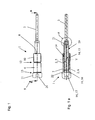
- FIG. 1 shows an ejector 1 of a device, not shown, for closing containers with closure or screw caps.
- a device for closing containers with closure or screw caps.
- Such devices are for example from the DE 202 18 523 U1 known, which will not be discussed further here and on supplies of closure or screw caps.
- unused or stuck closure or screw caps can be removed from a capping head, also not shown.
- the ejector 1 has an active element 2, which returns an ejection element 3 from an ejection position to an initial position, not shown.
- the active element 2 is advantageously designed as a magnetic (active) element 2, and has a permanent magnet 5 and a magnetizable wall portion 6 of a housing 7.
- the housing 7 has a foot side 8 and a head side 9 opposite thereto. From the foot 8, a threaded portion 10 extends in the direction of the head side 9. At the threaded portion 10, the magnetizable wall portion 6 connects, to which a head portion 11 connects.
- a groove 12 is arranged between the threaded portion 10 and the magnetizable wall portion 6 by way of example. Both sections 10 and 6 have, for example, approximately the same axial extension or length. Between the magnetizable wall portion 6 and the head part 11, a step 13 is arranged by way of example.
- a through-side open through hole 14 is arranged, which hineinerstreckt from the foot 8 in the head part 11.
- the through hole 14 is staged with a guide portion 15, a guide portion 16 and an actuating portion 17 executed as FIG. 1 a is to be taken.
- the guide section 15 extends from the foot 8 through the threaded portion 10 in the magnetizable wall portion 6 into and ends viewed in the longitudinal direction slightly in front of the head part 11. At the guide portion 15, the guide portion 16 connects, which with respect to the guide portion 15 a reduced clear Diameter, so that in the transition from the guide portion 15 to the guide portion 16, a step is formed ( FIG. 2 ).
- the guide section 16 has, relative to the guide section 15, a smaller axial length, which of course should only be by way of example.
- the guide section 16 extends by way of example only through the magnetizable wall section 6 ends at the transition to the head part 11 (FIG. FIG. 2 ).
- the actuating portion 17 extends through the head part 11 and has two areas 18 and 19.
- a transition region 18 adjoins the guide section 16 and is conically tapered.
- a cylindrical region 19 connects.
- the permanent magnet 5 is exemplified as a diametrically magnetized bar magnet.
- the two poles are in the FIGS. 1 a and 4 marked with N and S.
- the permanent magnet 5 is comprised by a sleeve 20, on which closure elements 21 and 22 in the exemplary embodiment as the foot cap 21 and as the head cap 22 are arranged on both the head side and the foot side.
- the sleeve 20 and the caps 21 and 22 may be made of a plastic, and are connected together.
- a cohesive connection in the embodiment can be selected as an adhesive or welded connection.
- the plastic coating of the permanent magnet 5 may e.g. have a corrosion-protective function.
- the permanent magnet 5 has, together with the comprehensive sleeve 20 has an outer diameter which is smaller than the clear diameter of both the guide portion 15 and the guide portion 16. Exemplary is in FIG. 4 an annular gap 23 between the outer circumference of the shell 20 with the permanent magnet 5 disposed therein and the magnetizable wall portion 6 along the line Y, that is shown in the region of the guide portion 15.
- the head-side cap 22 is an unillustrated plunger in conjunction.
- the plunger is connected to a force introduction element, not shown, on which an ejector control rod, not shown, acts.
- the plunger extends through the actuating portion 17 in the direction of the head-side cap 22.
- the head-side cap 22 can be regarded as a kind of buffer element, which avoids direct contact of plunger and permanent magnet 5.
- the head-side cap 22 can also be considered as a guide element within the guide portion 16.
- an axial guide slot 24 is arranged, which guides the force introduction element in the longitudinal direction of the housing 7. Due to the selected view, only a lower portion of the guide slot 24 can be seen, wherein an upper portion is not shown. Opposite to the recognizable in the plane of the drawing guide slot 24 and the recognizable guide slot 24, a further guide slot is provided, which is also fully closed. The force introduction element and the plunger arranged thereon are thus positively guided on the housing 7 on diametrically opposite guide slots.
- the Austosselement 3 is arranged, which can be referred to as Austossfinger.
- the Austosselement 3 is held by way of example in an arranged in the foot-side cap 21 receiving bore 25 with a receiving portion 26 adapted thereto positionally secure. It is conceivable to arrange a thread on the receiving region 26 in order to produce a screw connection, it being possible for an abutment flange to be arranged on the receiving region, which can abut against an end face of the cap 21.
- the Austosselement 3 acts on the unused or stuck closure or screw cap so that it pushed out of the capper head, i. Will get removed.
- the permanent magnet 5 is received in the housing 7 and movable relative to this or movable.
- the housing 7 is connected with its threaded portion 10 with the capper head, through which the Austosselement 3 and the Austossfinger same axis passes.
- the plunger acts on the head-side cap 22, that the permanent magnet 5 is displaced along its longitudinal axis in the direction of the foot 8 relative to the magnetizable wall portion 6 of the housing 7, which also connected to the permanent magnet 5 Austosselement 3 is moved to the Austossposition shown in the figures.
- the invention can be dispensed with mechanical active elements, such as springs, which are subject to great wear and are prone to failure.
- mechanical active elements such as springs
- no feather fins are formed in which dirt can accumulate.
- sealing elements are arranged, which seal the annular gap 23.
Landscapes
- Engineering & Computer Science (AREA)
- Mechanical Engineering (AREA)
- Closures For Containers (AREA)
- Sealing Of Jars (AREA)
Claims (8)
- Dispositif servant à fermer des récipients à l'aide de capuchons de fermeture ou de capuchon à visser, lequel dispositif présente un éjecteur (1), qui comprend un élément actif (2) qui ramène un élément d'éjection (3) d'une position d'éjection (4) dans une position de départ, caractérisé en ce que l'élément actif (2) est réalisé sous la forme d'un élément magnétique.
- Dispositif selon la revendication 1, caractérisé en ce que l'élément actif (2) présente un aimant permanent (5), qui est logé dans une section de paroi (6) pouvant être magnétisée d'un boîtier (7) de manière relativement mobile par rapport audit boîtier.
- Dispositif selon la revendication 1 ou 2, caractérisé en ce que l'élément actif (2) présente un aimant permanent (5) et une section de paroi (6) pouvant être magnétisée d'un boîtier (7).
- Dispositif selon l'une quelconque des revendications précédentes, caractérisé en ce que l'élément actif (2) présente un aimant permanent (5), qui est réalisé sous la forme d'un aimant droit à magnétisation diamétrale.
- Dispositif selon l'une quelconque des revendications précédentes, caractérisé en ce que l'élément actif (2) présente un aimant permanent (5), qui est logé dans une douille (20), qui présente des éléments de fermeture (21, 22).
- Dispositif selon l'une quelconque des revendications précédentes et selon la revendication 2 ou 3, caractérisé en ce que le boîtier (7) est ouvert côté inférieur, et en ce qu'il présente un alésage de passage (14).
- Dispositif selon l'une quelconque des revendications précédentes et selon la revendication 2 ou 3, caractérisé en ce que le boîtier (7) présente, au niveau de sa partie inférieure, une section filetée (10), à laquelle se raccorde une section de paroi (6) pouvant être magnétisée, au niveau de laquelle est disposée une partie tête (11).
- Dispositif selon la revendication 7, caractérisé en ce que la section filetée (10) est formée à partir d'un matériau pouvant être magnétisé.
Priority Applications (2)
| Application Number | Priority Date | Filing Date | Title |
|---|---|---|---|
| SI201130142T SI2576417T1 (sl) | 2010-05-31 | 2011-03-24 | Izmetalo magnetnih pokrovčkov v zapiralu |
| PL11711465T PL2576417T3 (pl) | 2010-05-31 | 2011-03-24 | Magnetyczny wypychacz nakrętek w zamykarce |
Applications Claiming Priority (2)
| Application Number | Priority Date | Filing Date | Title |
|---|---|---|---|
| DE102010022291A DE102010022291B3 (de) | 2010-05-31 | 2010-05-31 | Magnetkappenausstoßer im Verschließer |
| PCT/EP2011/001464 WO2011150991A1 (fr) | 2010-05-31 | 2011-03-24 | Dispositif aimanté d'éjection de capsules dans un dispositif de fermeture |
Publications (2)
| Publication Number | Publication Date |
|---|---|
| EP2576417A1 EP2576417A1 (fr) | 2013-04-10 |
| EP2576417B1 true EP2576417B1 (fr) | 2014-02-26 |
Family
ID=44144837
Family Applications (1)
| Application Number | Title | Priority Date | Filing Date |
|---|---|---|---|
| EP11711465.2A Active EP2576417B1 (fr) | 2010-05-31 | 2011-03-24 | Dispositif aimanté d'éjection de capsules dans un dispositif de fermeture |
Country Status (6)
| Country | Link |
|---|---|
| US (1) | US9388032B2 (fr) |
| EP (1) | EP2576417B1 (fr) |
| DE (1) | DE102010022291B3 (fr) |
| PL (1) | PL2576417T3 (fr) |
| SI (1) | SI2576417T1 (fr) |
| WO (1) | WO2011150991A1 (fr) |
Families Citing this family (6)
| Publication number | Priority date | Publication date | Assignee | Title |
|---|---|---|---|---|
| NL2009112C2 (en) * | 2012-07-03 | 2014-01-06 | Stork Food & Dairy Systems Bv | Machine for applying a cap to the neck of a container, and method using said machine. |
| IT201600106129A1 (it) * | 2016-10-21 | 2018-04-21 | Arol Spa | Testa di tappatura per applicazione di capsule su contenitori o bottiglie |
| IT201600106114A1 (it) * | 2016-10-21 | 2018-04-21 | Arol Spa | Gruppo di presa per testa di tappatura per applicazione di capsule su contenitori o bottiglie |
| IT201600106100A1 (it) * | 2016-10-21 | 2018-04-21 | Arol Spa | Testa di tappatura per applicazione di capsule su contenitori o bottiglie |
| DE102020114904A1 (de) | 2020-06-04 | 2021-12-09 | Krones Aktiengesellschaft | Vorrichtung zum Verschließen von Behältern mit magnetischem Verschlussauswurf |
| CN113321165B (zh) * | 2021-07-12 | 2024-08-16 | 安图实验仪器(郑州)有限公司 | 样本杯搬运及开合盖装置 |
Family Cites Families (12)
| Publication number | Priority date | Publication date | Assignee | Title |
|---|---|---|---|---|
| GB708994A (en) * | 1952-04-28 | 1954-05-12 | Metal Box Co Ltd | Improvements in or relating to machines for applying closures to containers |
| US5284001A (en) * | 1992-10-16 | 1994-02-08 | Anchor Hocking Packaging Co. | Spindle type straight line capper |
| US6508046B1 (en) | 2000-07-20 | 2003-01-21 | Fogg Filler Company | Self-adjusting capping chuck assembly for filler and/or capper device and associated method |
| DE10056990B4 (de) * | 2000-11-17 | 2005-07-21 | Khs Maschinen- Und Anlagenbau Ag | Vorrichtung zum Verschliessen von Flaschen und dergleichen Behälter mit Verschlusskappen durch Aufschrauben |
| DE10255196A1 (de) * | 2002-11-27 | 2004-07-15 | Khs Maschinen- Und Anlagenbau Ag | Vorrichtung zum Verschließen von Gefäßen |
| DE20218523U1 (de) * | 2002-11-29 | 2003-03-06 | KHS Maschinen- und Anlagenbau AG, 44143 Dortmund | Vorrichtung zum Verschließen von Gefäßen |
| DE102006035279A1 (de) * | 2006-07-31 | 2008-02-14 | Khs Ag | Verschließmaschine |
| DE102006039091A1 (de) * | 2006-08-19 | 2008-02-21 | Khs Ag | Vorrichtung zum Zuführen von Verschlüssen an eine Verschließmaschine |
| DE102007057857A1 (de) * | 2007-11-29 | 2009-06-04 | Khs Ag | Vorrichtung zum Verschließen von Behältern |
| US8118824B2 (en) * | 2008-09-16 | 2012-02-21 | Roche Diagnostics Operations, Inc. | Magnetic powered lancing drive |
| DE102008061848A1 (de) * | 2008-12-15 | 2010-07-01 | Khs Ag | Vorrichtung und Verfahren zum Verschließen von Behältern mit einem Verschluss |
| US20110167761A1 (en) * | 2009-07-14 | 2011-07-14 | Jha Vijay K | Low Inertia Capping Clutch |
-
2010
- 2010-05-31 DE DE102010022291A patent/DE102010022291B3/de not_active Expired - Fee Related
-
2011
- 2011-03-24 WO PCT/EP2011/001464 patent/WO2011150991A1/fr not_active Ceased
- 2011-03-24 US US13/582,791 patent/US9388032B2/en active Active
- 2011-03-24 PL PL11711465T patent/PL2576417T3/pl unknown
- 2011-03-24 SI SI201130142T patent/SI2576417T1/sl unknown
- 2011-03-24 EP EP11711465.2A patent/EP2576417B1/fr active Active
Also Published As
| Publication number | Publication date |
|---|---|
| PL2576417T3 (pl) | 2014-08-29 |
| EP2576417A1 (fr) | 2013-04-10 |
| WO2011150991A1 (fr) | 2011-12-08 |
| DE102010022291B3 (de) | 2011-12-01 |
| SI2576417T1 (sl) | 2014-05-30 |
| US20130000251A1 (en) | 2013-01-03 |
| US9388032B2 (en) | 2016-07-12 |
Similar Documents
| Publication | Publication Date | Title |
|---|---|---|
| EP2576417B1 (fr) | Dispositif aimanté d'éjection de capsules dans un dispositif de fermeture | |
| EP3445698B1 (fr) | Tête de bouchage pour fermer des récipients avec des bouchons | |
| EP2736834B1 (fr) | Dispositif pour la fermeture de récipients | |
| EP2724976B1 (fr) | Machine de fermeture pour récipients | |
| EP2958848B1 (fr) | Dispositif et machine pour la fermeture des recipients | |
| DE102009017109A1 (de) | Verschließer für Schraubkappen bzw. -verschlüsse | |
| EP2730533B1 (fr) | Dispositif d'application d'une fermeture sur un récipient | |
| EP2387542B1 (fr) | Tête de bouchage pour machine à boucher des récipients et machine à boucher des récipients correspondante | |
| DE102012219757A1 (de) | Verschließer für Behälter | |
| DE202011004883U1 (de) | Packtulpe zum kopfseitigen Ergreifen von Flaschen | |
| EP2376364B1 (fr) | Dispositif et procédé de fermeture de récipients au moyen d'un élément de fermeture | |
| DE102015115729A1 (de) | Behältertransporteur | |
| DE102004041749B3 (de) | Vorrichtung zum Verschliessen von Flaschen oder dergleichen Behälter | |
| EP2724979B1 (fr) | Machine de fermeture pour récipients | |
| EP2736835B1 (fr) | Dispositif de fermeture de récipients | |
| EP3313776B1 (fr) | Systeme de remplissage pour remplissage de recipients | |
| EP3028986B1 (fr) | Dispositif de transport de recipients | |
| DE10317326B4 (de) | Vorrichtung zum Einspannen eines Werkstücks auf einer drehantreibbaren Längsachse | |
| EP0508048A1 (fr) | Cartouche pour courrier par tube | |
| WO2014154202A1 (fr) | Support de fixation pour un positionneur de récipient et positionneur de récipient | |
| EP3828128B1 (fr) | Dispositif de fermeture pour récipient avec un bouchon à vis | |
| DE29911943U1 (de) | Flaschengreifer mit Drehvorrichtung | |
| DE102008027866A1 (de) | Vorrichtung zum Verschließen von Behältern mit einem Schraubverschluss | |
| EP3919430A1 (fr) | Dispositif de fermeture des récipients comprenant un éjecteur de capsules magnétique | |
| DE1432191A1 (de) | Verschluss,insbesondere Schraubverschluss mit Pinselhalterung fuer Flaschen u.dgl. |
Legal Events
| Date | Code | Title | Description |
|---|---|---|---|
| PUAI | Public reference made under article 153(3) epc to a published international application that has entered the european phase |
Free format text: ORIGINAL CODE: 0009012 |
|
| 17P | Request for examination filed |
Effective date: 20130102 |
|
| AK | Designated contracting states |
Kind code of ref document: A1 Designated state(s): AL AT BE BG CH CY CZ DE DK EE ES FI FR GB GR HR HU IE IS IT LI LT LU LV MC MK MT NL NO PL PT RO RS SE SI SK SM TR |
|
| DAX | Request for extension of the european patent (deleted) | ||
| GRAP | Despatch of communication of intention to grant a patent |
Free format text: ORIGINAL CODE: EPIDOSNIGR1 |
|
| RIC1 | Information provided on ipc code assigned before grant |
Ipc: B67B 3/20 20060101AFI20131017BHEP |
|
| INTG | Intention to grant announced |
Effective date: 20131101 |
|
| GRAS | Grant fee paid |
Free format text: ORIGINAL CODE: EPIDOSNIGR3 |
|
| GRAA | (expected) grant |
Free format text: ORIGINAL CODE: 0009210 |
|
| AK | Designated contracting states |
Kind code of ref document: B1 Designated state(s): AL AT BE BG CH CY CZ DE DK EE ES FI FR GB GR HR HU IE IS IT LI LT LU LV MC MK MT NL NO PL PT RO RS SE SI SK SM TR |
|
| REG | Reference to a national code |
Ref country code: GB Ref legal event code: FG4D Free format text: NOT ENGLISH |
|
| REG | Reference to a national code |
Ref country code: CH Ref legal event code: EP |
|
| REG | Reference to a national code |
Ref country code: AT Ref legal event code: REF Ref document number: 653476 Country of ref document: AT Kind code of ref document: T Effective date: 20140315 |
|
| REG | Reference to a national code |
Ref country code: IE Ref legal event code: FG4D Free format text: LANGUAGE OF EP DOCUMENT: GERMAN |
|
| REG | Reference to a national code |
Ref country code: DE Ref legal event code: R096 Ref document number: 502011002232 Country of ref document: DE Effective date: 20140410 |
|
| REG | Reference to a national code |
Ref country code: NL Ref legal event code: VDEP Effective date: 20140226 |
|
| REG | Reference to a national code |
Ref country code: LT Ref legal event code: MG4D |
|
| PG25 | Lapsed in a contracting state [announced via postgrant information from national office to epo] |
Ref country code: NO Free format text: LAPSE BECAUSE OF FAILURE TO SUBMIT A TRANSLATION OF THE DESCRIPTION OR TO PAY THE FEE WITHIN THE PRESCRIBED TIME-LIMIT Effective date: 20140526 Ref country code: IS Free format text: LAPSE BECAUSE OF FAILURE TO SUBMIT A TRANSLATION OF THE DESCRIPTION OR TO PAY THE FEE WITHIN THE PRESCRIBED TIME-LIMIT Effective date: 20140626 Ref country code: LT Free format text: LAPSE BECAUSE OF FAILURE TO SUBMIT A TRANSLATION OF THE DESCRIPTION OR TO PAY THE FEE WITHIN THE PRESCRIBED TIME-LIMIT Effective date: 20140226 |
|
| PG25 | Lapsed in a contracting state [announced via postgrant information from national office to epo] |
Ref country code: SE Free format text: LAPSE BECAUSE OF FAILURE TO SUBMIT A TRANSLATION OF THE DESCRIPTION OR TO PAY THE FEE WITHIN THE PRESCRIBED TIME-LIMIT Effective date: 20140226 Ref country code: FI Free format text: LAPSE BECAUSE OF FAILURE TO SUBMIT A TRANSLATION OF THE DESCRIPTION OR TO PAY THE FEE WITHIN THE PRESCRIBED TIME-LIMIT Effective date: 20140226 Ref country code: CY Free format text: LAPSE BECAUSE OF FAILURE TO SUBMIT A TRANSLATION OF THE DESCRIPTION OR TO PAY THE FEE WITHIN THE PRESCRIBED TIME-LIMIT Effective date: 20140226 Ref country code: NL Free format text: LAPSE BECAUSE OF FAILURE TO SUBMIT A TRANSLATION OF THE DESCRIPTION OR TO PAY THE FEE WITHIN THE PRESCRIBED TIME-LIMIT Effective date: 20140226 Ref country code: PT Free format text: LAPSE BECAUSE OF FAILURE TO SUBMIT A TRANSLATION OF THE DESCRIPTION OR TO PAY THE FEE WITHIN THE PRESCRIBED TIME-LIMIT Effective date: 20140626 |
|
| REG | Reference to a national code |
Ref country code: PL Ref legal event code: T3 |
|
| PG25 | Lapsed in a contracting state [announced via postgrant information from national office to epo] |
Ref country code: LV Free format text: LAPSE BECAUSE OF FAILURE TO SUBMIT A TRANSLATION OF THE DESCRIPTION OR TO PAY THE FEE WITHIN THE PRESCRIBED TIME-LIMIT Effective date: 20140226 Ref country code: HR Free format text: LAPSE BECAUSE OF FAILURE TO SUBMIT A TRANSLATION OF THE DESCRIPTION OR TO PAY THE FEE WITHIN THE PRESCRIBED TIME-LIMIT Effective date: 20140226 |
|
| PG25 | Lapsed in a contracting state [announced via postgrant information from national office to epo] |
Ref country code: RO Free format text: LAPSE BECAUSE OF FAILURE TO SUBMIT A TRANSLATION OF THE DESCRIPTION OR TO PAY THE FEE WITHIN THE PRESCRIBED TIME-LIMIT Effective date: 20140226 Ref country code: EE Free format text: LAPSE BECAUSE OF FAILURE TO SUBMIT A TRANSLATION OF THE DESCRIPTION OR TO PAY THE FEE WITHIN THE PRESCRIBED TIME-LIMIT Effective date: 20140226 Ref country code: DK Free format text: LAPSE BECAUSE OF FAILURE TO SUBMIT A TRANSLATION OF THE DESCRIPTION OR TO PAY THE FEE WITHIN THE PRESCRIBED TIME-LIMIT Effective date: 20140226 Ref country code: CZ Free format text: LAPSE BECAUSE OF FAILURE TO SUBMIT A TRANSLATION OF THE DESCRIPTION OR TO PAY THE FEE WITHIN THE PRESCRIBED TIME-LIMIT Effective date: 20140226 |
|
| REG | Reference to a national code |
Ref country code: CH Ref legal event code: PL |
|
| REG | Reference to a national code |
Ref country code: DE Ref legal event code: R097 Ref document number: 502011002232 Country of ref document: DE |
|
| PG25 | Lapsed in a contracting state [announced via postgrant information from national office to epo] |
Ref country code: ES Free format text: LAPSE BECAUSE OF FAILURE TO SUBMIT A TRANSLATION OF THE DESCRIPTION OR TO PAY THE FEE WITHIN THE PRESCRIBED TIME-LIMIT Effective date: 20140226 Ref country code: MC Free format text: LAPSE BECAUSE OF FAILURE TO SUBMIT A TRANSLATION OF THE DESCRIPTION OR TO PAY THE FEE WITHIN THE PRESCRIBED TIME-LIMIT Effective date: 20140226 Ref country code: SK Free format text: LAPSE BECAUSE OF FAILURE TO SUBMIT A TRANSLATION OF THE DESCRIPTION OR TO PAY THE FEE WITHIN THE PRESCRIBED TIME-LIMIT Effective date: 20140226 |
|
| REG | Reference to a national code |
Ref country code: IE Ref legal event code: MM4A |
|
| PLBE | No opposition filed within time limit |
Free format text: ORIGINAL CODE: 0009261 |
|
| STAA | Information on the status of an ep patent application or granted ep patent |
Free format text: STATUS: NO OPPOSITION FILED WITHIN TIME LIMIT |
|
| PG25 | Lapsed in a contracting state [announced via postgrant information from national office to epo] |
Ref country code: LI Free format text: LAPSE BECAUSE OF NON-PAYMENT OF DUE FEES Effective date: 20140331 Ref country code: CH Free format text: LAPSE BECAUSE OF NON-PAYMENT OF DUE FEES Effective date: 20140331 Ref country code: IE Free format text: LAPSE BECAUSE OF NON-PAYMENT OF DUE FEES Effective date: 20140324 |
|
| 26N | No opposition filed |
Effective date: 20141127 |
|
| REG | Reference to a national code |
Ref country code: DE Ref legal event code: R097 Ref document number: 502011002232 Country of ref document: DE Effective date: 20141127 |
|
| PG25 | Lapsed in a contracting state [announced via postgrant information from national office to epo] |
Ref country code: MT Free format text: LAPSE BECAUSE OF FAILURE TO SUBMIT A TRANSLATION OF THE DESCRIPTION OR TO PAY THE FEE WITHIN THE PRESCRIBED TIME-LIMIT Effective date: 20140226 |
|
| REG | Reference to a national code |
Ref country code: FR Ref legal event code: PLFP Year of fee payment: 6 |
|
| PG25 | Lapsed in a contracting state [announced via postgrant information from national office to epo] |
Ref country code: SM Free format text: LAPSE BECAUSE OF FAILURE TO SUBMIT A TRANSLATION OF THE DESCRIPTION OR TO PAY THE FEE WITHIN THE PRESCRIBED TIME-LIMIT Effective date: 20140226 |
|
| PG25 | Lapsed in a contracting state [announced via postgrant information from national office to epo] |
Ref country code: RS Free format text: LAPSE BECAUSE OF NON-PAYMENT OF DUE FEES Effective date: 20140226 Ref country code: BG Free format text: LAPSE BECAUSE OF FAILURE TO SUBMIT A TRANSLATION OF THE DESCRIPTION OR TO PAY THE FEE WITHIN THE PRESCRIBED TIME-LIMIT Effective date: 20140226 Ref country code: GR Free format text: LAPSE BECAUSE OF FAILURE TO SUBMIT A TRANSLATION OF THE DESCRIPTION OR TO PAY THE FEE WITHIN THE PRESCRIBED TIME-LIMIT Effective date: 20140527 |
|
| PG25 | Lapsed in a contracting state [announced via postgrant information from national office to epo] |
Ref country code: HU Free format text: LAPSE BECAUSE OF FAILURE TO SUBMIT A TRANSLATION OF THE DESCRIPTION OR TO PAY THE FEE WITHIN THE PRESCRIBED TIME-LIMIT; INVALID AB INITIO Effective date: 20110324 Ref country code: BE Free format text: LAPSE BECAUSE OF FAILURE TO SUBMIT A TRANSLATION OF THE DESCRIPTION OR TO PAY THE FEE WITHIN THE PRESCRIBED TIME-LIMIT Effective date: 20140331 Ref country code: LU Free format text: LAPSE BECAUSE OF NON-PAYMENT OF DUE FEES Effective date: 20140324 Ref country code: TR Free format text: LAPSE BECAUSE OF FAILURE TO SUBMIT A TRANSLATION OF THE DESCRIPTION OR TO PAY THE FEE WITHIN THE PRESCRIBED TIME-LIMIT Effective date: 20140226 |
|
| REG | Reference to a national code |
Ref country code: FR Ref legal event code: PLFP Year of fee payment: 7 |
|
| REG | Reference to a national code |
Ref country code: FR Ref legal event code: PLFP Year of fee payment: 8 |
|
| PGFP | Annual fee paid to national office [announced via postgrant information from national office to epo] |
Ref country code: GB Payment date: 20180321 Year of fee payment: 8 |
|
| PGFP | Annual fee paid to national office [announced via postgrant information from national office to epo] |
Ref country code: PL Payment date: 20180220 Year of fee payment: 8 Ref country code: AT Payment date: 20180322 Year of fee payment: 8 |
|
| PG25 | Lapsed in a contracting state [announced via postgrant information from national office to epo] |
Ref country code: MK Free format text: LAPSE BECAUSE OF FAILURE TO SUBMIT A TRANSLATION OF THE DESCRIPTION OR TO PAY THE FEE WITHIN THE PRESCRIBED TIME-LIMIT Effective date: 20140226 |
|
| PG25 | Lapsed in a contracting state [announced via postgrant information from national office to epo] |
Ref country code: AL Free format text: LAPSE BECAUSE OF FAILURE TO SUBMIT A TRANSLATION OF THE DESCRIPTION OR TO PAY THE FEE WITHIN THE PRESCRIBED TIME-LIMIT Effective date: 20140226 |
|
| REG | Reference to a national code |
Ref country code: AT Ref legal event code: MM01 Ref document number: 653476 Country of ref document: AT Kind code of ref document: T Effective date: 20190324 |
|
| GBPC | Gb: european patent ceased through non-payment of renewal fee |
Effective date: 20190324 |
|
| PG25 | Lapsed in a contracting state [announced via postgrant information from national office to epo] |
Ref country code: GB Free format text: LAPSE BECAUSE OF NON-PAYMENT OF DUE FEES Effective date: 20190324 Ref country code: AT Free format text: LAPSE BECAUSE OF NON-PAYMENT OF DUE FEES Effective date: 20190324 |
|
| PG25 | Lapsed in a contracting state [announced via postgrant information from national office to epo] |
Ref country code: PL Free format text: LAPSE BECAUSE OF NON-PAYMENT OF DUE FEES Effective date: 20190324 |
|
| PGFP | Annual fee paid to national office [announced via postgrant information from national office to epo] |
Ref country code: SI Payment date: 20250313 Year of fee payment: 15 |
|
| P01 | Opt-out of the competence of the unified patent court (upc) registered |
Free format text: CASE NUMBER: UPC_APP_0014582_2576417/2025 Effective date: 20251125 |
|
| PGFP | Annual fee paid to national office [announced via postgrant information from national office to epo] |
Ref country code: DE Payment date: 20260319 Year of fee payment: 16 |
|
| PGFP | Annual fee paid to national office [announced via postgrant information from national office to epo] |
Ref country code: IT Payment date: 20260324 Year of fee payment: 16 |
|
| PGFP | Annual fee paid to national office [announced via postgrant information from national office to epo] |
Ref country code: FR Payment date: 20260320 Year of fee payment: 16 |