EP2577025B1 - Verfahren zur erhöhung eines emissionskonformen belastungsbereichs für ein gas-dampf-system - Google Patents
Verfahren zur erhöhung eines emissionskonformen belastungsbereichs für ein gas-dampf-system Download PDFInfo
- Publication number
- EP2577025B1 EP2577025B1 EP10731893.3A EP10731893A EP2577025B1 EP 2577025 B1 EP2577025 B1 EP 2577025B1 EP 10731893 A EP10731893 A EP 10731893A EP 2577025 B1 EP2577025 B1 EP 2577025B1
- Authority
- EP
- European Patent Office
- Prior art keywords
- load level
- temperature
- turbine
- combustor
- air
- Prior art date
- Legal status (The legal status is an assumption and is not a legal conclusion. Google has not performed a legal analysis and makes no representation as to the accuracy of the status listed.)
- Not-in-force
Links
- 230000001965 increasing effect Effects 0.000 title claims description 43
- 238000000034 method Methods 0.000 title claims description 23
- 239000003570 air Substances 0.000 claims description 89
- 239000000446 fuel Substances 0.000 claims description 27
- 230000008859 change Effects 0.000 claims description 25
- 239000000203 mixture Substances 0.000 claims description 13
- 230000000694 effects Effects 0.000 claims description 11
- 238000001816 cooling Methods 0.000 claims description 9
- 239000012080 ambient air Substances 0.000 claims description 7
- 238000010438 heat treatment Methods 0.000 claims description 6
- 238000011084 recovery Methods 0.000 claims description 3
- 238000010248 power generation Methods 0.000 claims description 2
- 239000013589 supplement Substances 0.000 claims description 2
- 239000007789 gas Substances 0.000 description 76
- GQPLMRYTRLFLPF-UHFFFAOYSA-N Nitrous Oxide Chemical compound [O-][N+]#N GQPLMRYTRLFLPF-UHFFFAOYSA-N 0.000 description 10
- 238000002347 injection Methods 0.000 description 8
- 239000007924 injection Substances 0.000 description 8
- 238000002485 combustion reaction Methods 0.000 description 7
- 230000001276 controlling effect Effects 0.000 description 5
- 239000001272 nitrous oxide Substances 0.000 description 5
- 230000009467 reduction Effects 0.000 description 5
- 238000002156 mixing Methods 0.000 description 4
- 230000001105 regulatory effect Effects 0.000 description 4
- 230000007613 environmental effect Effects 0.000 description 3
- 230000002411 adverse Effects 0.000 description 2
- 230000009286 beneficial effect Effects 0.000 description 2
- 238000010586 diagram Methods 0.000 description 2
- 230000006870 function Effects 0.000 description 2
- 230000002459 sustained effect Effects 0.000 description 2
- 230000001360 synchronised effect Effects 0.000 description 2
- 230000007704 transition Effects 0.000 description 2
- 238000011144 upstream manufacturing Methods 0.000 description 2
- UGFAIRIUMAVXCW-UHFFFAOYSA-N Carbon monoxide Chemical compound [O+]#[C-] UGFAIRIUMAVXCW-UHFFFAOYSA-N 0.000 description 1
- 238000013459 approach Methods 0.000 description 1
- 229910002091 carbon monoxide Inorganic materials 0.000 description 1
- 239000000567 combustion gas Substances 0.000 description 1
- 230000003028 elevating effect Effects 0.000 description 1
- 238000004519 manufacturing process Methods 0.000 description 1
- 238000012544 monitoring process Methods 0.000 description 1
- 230000002265 prevention Effects 0.000 description 1
- 230000008569 process Effects 0.000 description 1
- 230000001052 transient effect Effects 0.000 description 1
Images


Classifications
-
- F—MECHANICAL ENGINEERING; LIGHTING; HEATING; WEAPONS; BLASTING
- F02—COMBUSTION ENGINES; HOT-GAS OR COMBUSTION-PRODUCT ENGINE PLANTS
- F02C—GAS-TURBINE PLANTS; AIR INTAKES FOR JET-PROPULSION PLANTS; CONTROLLING FUEL SUPPLY IN AIR-BREATHING JET-PROPULSION PLANTS
- F02C9/00—Controlling gas-turbine plants; Controlling fuel supply in air- breathing jet-propulsion plants
- F02C9/48—Control of fuel supply conjointly with another control of the plant
- F02C9/50—Control of fuel supply conjointly with another control of the plant with control of working fluid flow
- F02C9/52—Control of fuel supply conjointly with another control of the plant with control of working fluid flow by bleeding or by-passing the working fluid
-
- F—MECHANICAL ENGINEERING; LIGHTING; HEATING; WEAPONS; BLASTING
- F02—COMBUSTION ENGINES; HOT-GAS OR COMBUSTION-PRODUCT ENGINE PLANTS
- F02C—GAS-TURBINE PLANTS; AIR INTAKES FOR JET-PROPULSION PLANTS; CONTROLLING FUEL SUPPLY IN AIR-BREATHING JET-PROPULSION PLANTS
- F02C9/00—Controlling gas-turbine plants; Controlling fuel supply in air- breathing jet-propulsion plants
- F02C9/48—Control of fuel supply conjointly with another control of the plant
- F02C9/50—Control of fuel supply conjointly with another control of the plant with control of working fluid flow
- F02C9/54—Control of fuel supply conjointly with another control of the plant with control of working fluid flow by throttling the working fluid, by adjusting vanes
-
- F—MECHANICAL ENGINEERING; LIGHTING; HEATING; WEAPONS; BLASTING
- F05—INDEXING SCHEMES RELATING TO ENGINES OR PUMPS IN VARIOUS SUBCLASSES OF CLASSES F01-F04
- F05D—INDEXING SCHEME FOR ASPECTS RELATING TO NON-POSITIVE-DISPLACEMENT MACHINES OR ENGINES, GAS-TURBINES OR JET-PROPULSION PLANTS
- F05D2270/00—Control
- F05D2270/01—Purpose of the control system
- F05D2270/08—Purpose of the control system to produce clean exhaust gases
- F05D2270/082—Purpose of the control system to produce clean exhaust gases with as little NOx as possible
-
- F—MECHANICAL ENGINEERING; LIGHTING; HEATING; WEAPONS; BLASTING
- F05—INDEXING SCHEMES RELATING TO ENGINES OR PUMPS IN VARIOUS SUBCLASSES OF CLASSES F01-F04
- F05D—INDEXING SCHEME FOR ASPECTS RELATING TO NON-POSITIVE-DISPLACEMENT MACHINES OR ENGINES, GAS-TURBINES OR JET-PROPULSION PLANTS
- F05D2270/00—Control
- F05D2270/01—Purpose of the control system
- F05D2270/08—Purpose of the control system to produce clean exhaust gases
- F05D2270/083—Purpose of the control system to produce clean exhaust gases by monitoring combustion conditions
- F05D2270/0831—Purpose of the control system to produce clean exhaust gases by monitoring combustion conditions indirectly, at the exhaust
-
- Y—GENERAL TAGGING OF NEW TECHNOLOGICAL DEVELOPMENTS; GENERAL TAGGING OF CROSS-SECTIONAL TECHNOLOGIES SPANNING OVER SEVERAL SECTIONS OF THE IPC; TECHNICAL SUBJECTS COVERED BY FORMER USPC CROSS-REFERENCE ART COLLECTIONS [XRACs] AND DIGESTS
- Y02—TECHNOLOGIES OR APPLICATIONS FOR MITIGATION OR ADAPTATION AGAINST CLIMATE CHANGE
- Y02E—REDUCTION OF GREENHOUSE GAS [GHG] EMISSIONS, RELATED TO ENERGY GENERATION, TRANSMISSION OR DISTRIBUTION
- Y02E20/00—Combustion technologies with mitigation potential
- Y02E20/16—Combined cycle power plant [CCPP], or combined cycle gas turbine [CCGT]
Definitions
- the invention relates to combined-cycle systems, and more specifically, to a method for increasing a load range over which a combined-cycle system can operate while still achieving an emission compliant status.
- Combined-cycle plants typically run at or near full power output level during day-time operation.
- the gas turbine system (Brayton cycle)
- exhaust emissions of the combined-cycle system must comply with legal requirements which are specific to the governmental authority over the geographic locality in which the plant operates. Generally, this necessitates that a minimum flame temperature be sustained during gas turbine operation. In the past it has not been possible to sustain the minimum flame temperature at less than about 70 percent of the maximum operating load level due to limitations imposed by compressor and inlet guide vane designs which necessitate the production of a minimum flow rate of compressed air which is in excess of a desired flow rate for power levels of less than about 70%.
- US 2009/0056342 A1 discloses a method for operating at partial load a gas turbine system having a compressor, a combustor, and a turbine.
- the method includes the steps of lowering a flow of fuel to the combustor, extracting air from the compressor so as to lower a flow of air to the compressor, and returning the extracted air to the turbine or a component of the gas turbine system other than the combustor. Extracting air from the compressor raises a combustion temperature within the combustor. Raising the combustion temperature maintains a combustion exhaust below a predetermined level, maintains stable combustion, and extends turbine turndown values.
- emissions compliant refers to providing levels of CO (carbon monoxide) and/or NO x (nitrous oxide) in the exhaust gas of the gas turbine which are within regulatory limits which may vary based on geographic area.
- the invention is not limited to any specific regulatory limits or emissions levels.
- emissions compliant limits for CO and NO x have, in the past, been generally met by maintaining a minimum fuel-to-air ratio (FTA) within the combustor of the gas turbine engine, such that a minimum flame temperature is maintained, a characteristic minimum gas turbine exhaust temperature may be monitored to assess whether operation the gas turbine system is operating within the regulatory limits.
- FTA fuel-to-air ratio
- Disclosed embodiments of the present invention provide a method for load reduction during a turn-down in power output from the combined-cycle system.
- the inventors have recognized that, in a gas turbine system of a combined-cycle system, high flame temperatures needed to comply with emissions limits can be sustained by diverting air which would otherwise pass from the compressor stage through the combustor.
- the diverted air may be sent into disc cavities of the gas turbine for cooling, and/or into a heat recovery steam generator (HRSG).
- HRSG heat recovery steam generator
- a feature of the invention is the prevention of undesirably large and relatively rapid temperature fluctuations at the input stage to the HRSG where a mixture of the diverted air and the hot exhaust gases enter the HRSG. That is, when attempting to control flame temperature by diverting compressed air, the mixing of that same diverted air with relatively hot exhaust gas can cause large time varying temperature excursions and this can adversely affect the integrity and longevity of system components.
- the inventors have also recognized that a net cooling of the gases entering the HRSG can occur based on the volume of air flow which bypasses the combustor and mixes with the hot exhaust gases, to form a mixture of the bypassed air and the exhaust gas sent from the outlet of the turbine, prior to entry into the HRSG.
- the relatively cool air extracted from the compressor and injected at a point downstream of the gas turbine, mixes with the exhaust gases output from the turbine, the exhaust gas cools prior to entry into the HRSG. This, in turn, can influence the performance of the Rankine cycle.
- This bypass of air aids in sustaining a high flame temperature, and results in an elevated exhaust gas temperature.
- the exhaust gas temperature can be elevated or otherwise regulated by a control system to influence the temperature of gases entering the HRSG.
- the control system can compare the exhaust temperature to an exhaust temperature set point, and then adjust the exhaust temperature based on exhaust temperature set points.
- the control system adjusts the exhaust gas temperature to a given set point by varying the amount of ambient air entering into the gas turbine combustor. This can be effected, in part, by opening or closing inlet guide vanes which control the amount of ambient air entering into the compressor, thereby affecting the fuel-to-air ratio (FTA) within the combustor.
- FFA fuel-to-air ratio
- the control system closes the inlet guide vanes and this reduces the volumetric flow rate of ambient air into the combustor, which increases the FTA within the combustor and thereby elevates both the flame temperature and the exhaust temperature of the gas turbine system.
- the inventors have discovered that the cooling effects of the compressed air which bypasses the combustor can be controlled based on a change in the gas turbine exhaust temperature, specifically when the flame temperature set point is adjusted to elevate the exhaust gas temperature. That is, the magnitude of temperature transients at the HRSG can be managed by simultaneously controlling a combination of exhaust temperature set points and relatively cool bypass gas flow volumes which would otherwise lead to large, rapid temperature swings at the HRSG.
- the temperature transients at the HRSG may be minimized or eliminated by simultaneously controlling (i) the time rate of change of the injection of relatively cool bypass air into the HRSG, which causes a temperature depression, and (ii) the time rate of change of an increase in the temperature of exhaust gases output from the turbine.
- the magnitude of the temperature transients at the HRSG may be limited by simultaneously controlling a rate of change in the volume of the flow which bypasses the combustor and controlling the turbine exhaust temperature set point.
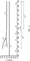
- conventional combined-cycle systems operate over a limited load range 64 from a maximum load level 52 to a load level 54, while maintaining an emissions compliant status.
- This arrangement has several drawbacks, such as an inability to further reduce the fuel consumption rate below the rate corresponding to the intermediate load level 54, without lowering the FTA below a minimum FTA required to remain emissions compliant.
- the embodiments of the present invention provide a method for extending the emissions compliant range to a load level range 50 for a gas turbine system 11, i.e., a wider range of reduced operating load levels without creating an adverse impact on the downstream HRSG.
- the load level 54 is only an intermediate load level in that larger range 50 and is referred to as such.
- the emissions compliant load level range 50 can extend down to 50% of the maximum operating load level.
- a gas turbine system 11 of the combined-cycle system 10 includes inlet guide vanes 12 for directing ambient air into a compressor 14, from which compressed air passes into a combustor 16.
- the compressed air reacts with fuel 17 which flows from a fuel source 19, and delivers hot combustion exhaust gas to a turbine 18.
- the combustion gas expands to generate power, and the hot exhaust gas is then output from an outlet 42 of the turbine 18 to a heat recovery steam generator (HRSG) 20 positioned downstream from the outlet 42.
- HRSG heat recovery steam generator
- the compressor 14 outputs compressed air to the combustor 16, but need not output all of the compressed air to the combustor 16.
- the compressed air that is not output to the combustor 16 may be routed through one or more flow lines 21, 25, 33, 35, 40, 41, each including a valve 22, 24, 34, 36, 38 or 43 to selectively control flow of air therethrough.
- a pair of first valves 22, 24 is positioned along respective flow lines 21,25 which joins different stages (e.g., the eighth and eleventh stages) 23, 26, respectively, of the compressor 14 to different stages (e.g., second and third stages) 30,32, respectively, of the turbine 18.
- the second valves 34,36 control the flow of compressed air through the lines 33, 35, respectively, each being positioned in parallel with the lines 21 or 25 so that valve 22 acts in parallel with valve 34 and valve 24 acts in parallel with valve 36.
- a bleed valve 38 is positioned in a bypass flow line 40 which injects a flow of compressed air from the stage 26 of the compressor 14 to an injection point 47downstream of the outlet 42 of the turbine 18, to form a mixture of bypassed air and the exhaust gas sent from the outlet 42 of the turbine 18 prior to entry into the inlet entry 51 of the HRSG 20.
- bleed valve 38 Upon opening of the bleed valve 38, a bypass flow of compressed air travels around the combustor 16 and is injected at the point 47 downstream of the turbine outlet 42 and upstream of the inlet entry 51 to the HRSG 20.
- the bleed valve 38 is positioned in series with a secondary bleed valve 44, in the bypass flow line 40.
- the gas turbine system 11 includes a bleed valve 43 positioned in a bypass flow line 41 which injects a flow of compressed air from the stage 27 of the compressor 14 to a point 48 downstream of the turbine outlet 42 of the turbine 18, and upstream of the injection point 47 of the bypass flow line 40.
- a control system 71 is coupled to each of the valves 22, 24, 34, 36, 38 and 44 as well as the inlet guide vanes 12, and is configured to monitor and control the position of the inlet guide vanes 12 and the valves 22, 24, 34, 36, 38, based on one or more parameters of the combined-cycle system 10, such as power demand or load level of the combined-cycle system 10.
- control system 71 may switch into a partial-load level mode, with the control system 71 monitoring the load level of the combined-cycle system 10 and varying the position of one or more of the valves 22, 24, 34, 36, 38 and/or the inlet guide vanes 12, as discussed below, to ensure that the gas turbine system 11 is emissions compliant throughout the partial-load level operation, e.g., throughout the extended range 50.
- a plant operator may manually intervene to turn the power output down, with the control system 71 then deploying a partial load mode of operation.
- the foregoing reductions may occur at the commencement of a low-power demand period, such as during night operation, when the power demand placed on the combined-cycle system 10 falls below a designated level.
- the control system 71 includes an outlet temperature controller (OTC) 70 which is configured to (i) monitor the temperature of exhaust gas emitted from the outlet 42 of the turbine 18, (ii) compare the exhaust gas temperature with the temperature set point (stored in a memory of the OTC) and (iii) vary a position of the inlet guide vanes 12, based on this comparison, such that the amount of ambient air entering the compressor 14, and, in turn, the amount of compressed air entering the combustor 16 is adjusted to bring the exhaust temperature to equal the set point.
- OTC outlet temperature controller
- the control system 71 switches into a partial-load control mode to monitor the load level of the gas turbine system 11 while varying one or more of the inlet guide vanes and the valves 22, 24, 34, 36, 38 to ensure that the system 11 remains emissions compliant.
- the control system 71 continues to adjust one or more of the inlet guide vanes 12 and valves 22, 24, 34, 36, 38, as described in the sequence below.
- the supply of fuel 17 to the combustor 16 is further reduced, while a supply of air to the combustor 16 is simultaneously reduced to maintain a suitable FTA to sustain an emissions compliant flame temperature which is determinable based on a measurable temperature of the exhaust gases at the outlet 42 of the turbine 18.
- the minimum exhaust temperature 62, corresponding to an emissions compliant flame temperature is 582 °C (1080°F), for a SGT6-5000F model gas turbine system.
- the numerical value of the exhaust temperature corresponding to an emissions compliant flame temperature is merely exemplary and embodiments of the present invention are applicable to a variety of gas turbine designs having varied emission compliant flame temperatures and resulting exhaust gas temperatures.
- the fuel supply 17 is reduced while, simultaneously, the supply of air to the combustor 16 is reduced in a sequence of stages.
- the supply of fuel 17 to the combustor 16 is reduced to a first level to bring the output down to the load level 54.
- the inlet guide vanes 12 are adjusted to reduce air intake, as the operating load level diminishes from the maximum load level 52 to the first intermediate load level 54.
- the supply of fuel 17 to the combustor 16 is further reduced to a second level to bring the output down to the second intermediate load level 56 while simultaneously opening the pair of first valves 22, 24, to provide a first bypass flow of air through line 21 and around the combustor 16, and a second bypass flow of air through line 25 and around the combustor 16 from the compressor 14 to the turbine 18.
- the operating load is thus reduced from the first intermediate load level 54 to the second intermediate load level 56.
- the first valves 22,24 are opened at a rate of 10% per second, with a waiting period of 10 seconds between the opening of the valve 22 and the opening of the valve 24.
- the supply of fuel 17 to the combustor 16 is further reduced to a third level to bring the output down to a third intermediate load level 57.
- second valves 34, 36 positioned in parallel with the first valves 22,24 are opened to augment the amount of diverted flow, i.e., to supplement the first bypass flow through flow line 21 and the second bypass flow through line 25 around the combustor 16 via the valves 22, 24 from the compressor 14 to the turbine 18, as the operating load is reduced from the second intermediate load level 56 to the third intermediate load level 57.
- a waiting period of 40 seconds is implemented between the time that the first valves 22,24 are fully opened and when the opening of the second valves 34,36 begins.
- the second valves 34, 36 are opened at a rate of 5% per second, with a waiting period of 20 seconds between the time the opening of the valve 34 is initiated and the opening of the valve 36 is initiated.
- the system 71 adjusts the first bypass flow through the line 21 and the second bypass flow through the line 25 by controlling the first and second pairs of valves (22,24), (34,36) so that air from the high and low pressure stages 23,26 of the compressor 14 is bypassed to the stages 30,32 of the turbine 18, respectively. This limits the temperature in second and third disc cavity regions of the stages 30,32 of the turbine 18.
- the first flow and the second flow are directed from the stages 23, 26 of the compressor 14 to the stages 30, 32 of the turbine 18, respectively, to limit the temperature in the second disc cavity region (between the stages 30 and 32) and in the third disc cavity region (between the stages 32 and 31) of the turbine 18, to a desired temperature range.
- the gas turbine system 11 of the combined-cycle system 10 includes a control system 71 having an outlet temperature controller (OTC) 70 to compare the temperature of the exhaust gas at the outlet 42 with an adjustable exhaust temperature set point stored in a memory of the OTC 70. If the exhaust temperature is less than the exhaust temperature set point, the OTC 70 sends a signal to close the inlet guide vanes 12 and thereby reduce the supply of compressed air to the combustor 16. This increases the FTA within the combustor 16 and raises the exhaust temperature to the exhaust temperature set point. Conversely, when the exhaust temperature is greater than the exhaust temperature set point, the OTC 70 sends a signal to the inlet guide vanes 12 to open the inlet guide vanes 12 (to an open position or a near-open position).
- OTC outlet temperature controller
- the inlet guide vanes 12 are closed (to a closed position or a near-closed position) in order to reduce the load level from the maximum level 52 to the first intermediate level 54. Subsequently, while the operating load level is reduced to the intermediate load level 57, the first flow and the second flow of air around the combustor 16 increase the FTA and the exhaust temperature rises above the exhaust temperature set point. This causes the OTC 70 to open the inlet guide vanes 12 from the closed position (or near-closed position) to an open position (or near-open position).
- the exhaust temperature and the exhaust temperature set point may both be 566 °C (1050° F), and the inlet guide vanes 12 may be set to a closed position (e.g., 35 degrees relative to a fully open/closed position of 0/35 degrees - measurable with respect to the direction of flow of ambient air entering the inlet guide vanes 12 of the compressor).
- a closed position e.g., 35 degrees relative to a fully open/closed position of 0/35 degrees - measurable with respect to the direction of flow of ambient air entering the inlet guide vanes 12 of the compressor.
- the OTC 70 may rise to 577 °C (1070F), after which time the OTC 70 compares the exhaust temperature 60 at 577 °C (1070 ° F) to the exhaust temperature set point of 566 °C (1050 °F), and transmits a signal to open the inlet guide vanes 12, until the exhaust temperature equals the exhaust temperature set point.
- the operating load level is reduced from the intermediate load level 57 to an emissions compliant load level limit 58 (see FIG. 3 )
- there is an increase in flow of compressor air on line 40 which bypasses the combustor 16 as it travels from the compressor 14 to the injection point 47 downstream of the turbine outlet 42 and into the inlet 51 of the HRSG 20.
- This bypass flow on line 40 is increased as the operating load level is reduced from the intermediate level 57 to an emissions compliant load level limit 58.
- This further reduced power corresponds to the extended emissions compliant range 50.
- the operating load level need not be reduced the full range, e.g., to the emissions compliant load level limit 58, and may be reduced from any higher level 57 to any lower load level within the emissions compliant load level range 50.
- the control system 71 is configured to selectively open the bleed valve 38 based on the rate at which the bypass flow through line 40 increases, e.g., based on a predetermined flow rate schedule such as that used in conjunction with ramping the set point for the exhaust temperature.
- the system 71 controls the bleed valve 38 in accord with a predefined CV (control valve) operating curve (e.g., stored in memory of the system 71), according to which a variable flow rate through the bleed valve 38 is provided.
- the bypass flow of compressor air on line 40 mixes with the exhaust gas travelling to the HRSG from the downstream line 45 from the outlet 42 of the turbine 18, to lower the temperature 61 of the resulting mixture of bypassed air and exhaust gas at the HRSG 20.
- the bypass flow of compressed air through the line 40 has a cooling effect on the temperature 61 of the resulting mixture at the HRSG 20.
- the exhaust temperature set point of the turbine 18 is increased, by the OTC 70, to increase the temperature of the exhaust gas, at the outlet 42 of the turbine 18, in a coordinated manner with the bypass flow of compressed air through the line 40.
- increasing the exhaust temperature set point has a heating effect on the mixture of the bypassed air and the exhaust gas at the HRSG 20.
- An exemplary increase in the exhaust gas temperature is shown by the temperature curve 60.
- the exhaust temperature set point is increased as the system 11 approaches the load level limit 58
- the exhaust temperature increases when the OTC 70 determines that the exhaust temperature is less than the increasing exhaust temperature set point. Consequently, the inlet guide vanes 12 are closed to reduce the air supplied to the combustor 16 and increase the FTA within the combustor 16.
- the inlet guide vanes 12 may be initially closed as the operating load is reduced to the first intermediate load level 54, but are then opened as the operating load level is further reduced to the intermediate load level 57 because the amount of air being bypassed exceeds the reduction necessary for emissions compliance at the reduced power level, followed by being closed again as the operating load level is reduced to the emissions compliant load level limit 58.
- the fully open position of the inlet guide vanes 12 is referenced as zero degrees, while the position of the inlet guide vanes 12 when air intake is most limited is referenced as 35 degrees relative to the fully open position.
- the turbine exhaust temperature by increasing the exhaust temperature set point, the turbine exhaust temperature (see temperature curve 60) remains above the minimum exhaust temperature 62 which corresponds to the minimum flame temperature within the combustor 16 that is emissions compliant. Elevation of the exhaust temperature above the minimum temperature 62 has the effect of further elevating the temperature when the exhaust gases mix with the bypass flows of compressor air as indicated by the mixed gas temperature curve 61.
- the controlled blending limits the time rate of change of the temperature fluctuations of the resulting mixture of exhaust gas and compressor air entering the HRSG 20 to an upper limit of the time rate of change, above which damage to the HRSG 20 occurs. That is, the control system 71 limits the range of temperature fluctuation and/or rate of change in temperature fluctuations of the gases entering the HRSG to the upper limit of the time rate of change.
- the upper limit of the time rate of change may be 10 degrees/minute, for example.
- the change in downstream exhaust temperature for gases entering the HRSG (per curve 61) is relatively small and approximately linear with respect to the change in load level.
- the characteristic of curve 61 being exemplary, results because the exhaust temperature 60 continuously increases as the operating load level is reduced. That is, as the system 11 transitions from the intermediate load level 57 to the emissions compliant load level limit 58, the increasing volume of the relatively cool bypass flow on line 40 is mixed with exhaust gas of increasing temperature.
- control system 71 (including the OTC 70) is provided with a synchronized schedule according to which an increase in the bleed flow through line 40 and an increase in the exhaust temperature set point are coordinated to minimize the magnitude of temperature excursions at the HRSG.
- the schedule provides a rate of air flow which is a function of the reduction of the operating load level, such as from the intermediate load level 57 to the emissions compliant load level limit 58, for example.
- the control system 71 controls the air flow rate to provide a maximum air flow rate, which occurs when the operating load level is at the emissions compliant load level limit 58.
- the schedule may instruct the control system 71 (via the OTC 70) to increase the bleed flow through line 40 to fifty percent of the maximum value and increase the exhaust temperature set point by half of the programmed maximum exhaust temperature set point increase, when the operating load level is being reduced to a half-way point between the intermediate load level 57 and the emissions compliant load level limit 58.
- the schedule may instruct the control system 71 to increase the bleed flow rate through line 40 from zero to 22.68 kg/min (zero to 50 lbs/min) (50 percent of the maximum bleed flow rate of 45.36 kg/min (100 lbs/min)), and instruct the control system 71 (OTC 70) to increase the exhaust temperature set point from 566 °C (1050° F) to 593 °C (1100° F) (50 percent to the maximum exhaust temperature set point of 621 °C (1150° F)).
- the control system 71 ensures a coordinated increase of the bleed flow rate through the line 40 with the change in exhaust temperature set point.
- the schedule includes a series of air flow rates coordinated with a series of exhaust temperature set points to effect a continual decrease in load level from a maximum output level 52 to the emissions compliant load level limit 58.
- the bypass flow through the line 40 may be increased in stages, as the load is reduced from the intermediate load level 57 to the emissions compliant load level limit 58.
- the flow through line 40 may be increased by a first portion during a first time interval; and then increased by a second portion during a second time interval, where the first and second portions within the respective first and second time intervals are based on the predetermined rate at which the bypass flow rate is delivered to the HRSG 20.
- the exhaust temperature set point is also incrementally increased to a first temperature and then to a second temperature, during the first time interval and the second interval, respectively.
- each adjustment of the exhaust temperature set point, during the first and second time intervals is based on the predetermined rate of temperature increase which is coordinated with a corresponding change in volumetric bypass flow rate through the line 40.
- the bypass flow through the line 40 is controlled by movement of the bleed valve 38.
- the incremental increases in the flow through the line 40 may be accomplished in accord with the predefined CV curve for opening the bleed valve 38 by predetermined amounts during the first and second time intervals, respectively.
- the bleed valve 38 is partially opened by the first amount during the first time interval, to increase the bypass flow through the line 40, to a percentage of a maximum flow rate, and is then fully opened during the second time interval, to increase the bypass flow through the line 40 to the maximum flow rate.
- the maximum flow rate may be expressed as a maximum volumetric mass flow rate, such as 45.36 kg/min (100 lbs/min), for example.
- the exhaust temperature set point is increased by the first temperature during the first time interval, such that the exhaust temperature is greater than the emissions compliant threshold temperature 62 (which is indicative of a threshold flame temperature within the combustor 16); and the time rate of change of the downstream temperature 61 at the HRSG 20 (indicated by the temperature curve 61) is less than the threshold time upper limit of the time rate of change of the downstream temperature at the HRSG 20.
- the exhaust temperature set point is increased by the second temperature during the second time interval, such that the exhaust temperature is greater than the temperature 62 corresponding to the emissions compliant threshold flame temperature and the time rate of change of the downstream temperature at the HRSG 20 (per curve 61) is less than the upper limit of the time rate of change, after the bleed valve 38 has been fully opened, and the bypass flow through the flow line 40 has increased to the maximum flow.
- the bypass flow through the flow line 40 may increase from zero to 22.68 kg/min (zero to 50 lbs/min) during the first time period, while the exhaust temperature set point increases from 566 °C (1050° F) to 593 °C (1100° F).
- bypass flow through the line 40 may increase from 22.68 kg/min (50 lbs/min) to 45.36 kg/min (100 lbs/min), while the exhaust temperature set point increases from 593 °C (1100° F) to 621 °C (1150° F), during the second time period.
- a gas turbine system 11' of a combined-cycle system 10' features a first portion of bypass flow passing through a bypass line 40' and a first bleed valve 38' during the first time interval.
- Those elements of the combined-cycle 10' illustrated in FIG. 2 are similar to those equivalent-numbered elements of the combined-cycle 10 illustrated in FIG. 1 , without prime notation, discussed above, and require no further discussion herein.
- the first bleed valve 38' is positioned to pass a first portion of the bypass flow from a high pressure stage 26' of the compressor 14' through an existing line 40' between the high pressure stage 26' of the compressor 14' and to an injection point 47' downstream of the outlet 42' of the turbine 18'.
- the second portion of the bypass flows through a line 37' between the high pressure stage 26' of the compressor 14' and a second injection point 49', and into an existing low pressure line 41' between a low pressure stage 27' of the compressor, downstream of the outlet 42' of the turbine 18'.
- the line 37' includes a second bleed valve 39' to pass the second portion of the bypass flow from the high pressure stage 26' of the compressor 14' to the second injection point 49' within the line 41', and subsequently downstream of the outlet 42' of the turbine 18', during the second time interval.
- Increasing the bypass flow by the first portion is accomplished by fully opening the bleed valve 38' during the first time interval, while increasing the bypass flow by the second portion is accomplished by fully opening the second bleed valve 39' during the second time interval.
- the gas turbine system 11' includes a control system 71' to switch into a partial-load mode, upon one or more parameters of the combined-cycle system 10' falling below a threshold value.
- the control system 71' monitors and controls the inlet guide vanes 12' and valves 22', 24', 34', 36', 38', 39', during the partial-load mode, to ensure that the gas turbine system 11' remains emissions compliant.
- the fuel 17 provided to the combustor 16 in FIG. 1 is in a ratio of premix stage to pilot stage.
- a premix stage of the fuel 17 is beneficial for the emissions compliance of the fuel 17, including the levels of CO and NOx within the fuel 17, after combustion within the combustor 16.
- the pilot stage of the fuel 17 is beneficial for the stability of the flame within the combustor 16.
- the inventors have recognized that, as the operating load is reduced from the intermediate load level 57 to the emissions compliant load level limit 58, increasing the exhaust temperature set point will continuously increase the exhaust temperature at the outlet 42 of the turbine 18.
- the stability of the flame within the combustor 16 is proportional to the flame temperature within the combustor 16, which in-turn affects the exhaust temperature, and thus the pilot stage component may be continuously lowered as the combustion exhaust temperature setpoint is increased while the operating load is reduced to the emissions compliant load level limit 58.
- the inventors have recognized that emissions compliance may be increasingly challenging as the operating load is reduced to the emissions compliant load level limit 58, and thus the premix stage may be continuously increased as the operating load is reduced to the emissions compliant load level limit 58.
- a ratio of the premix stage to the pilot stage in the fuel 17 delivered to the combustor 16 from the fuel source 19 is increased , in coordination with the increasing of the bypass flow through the line 40 and exhaust temperature set point, as the operating load is reduced from intermediate load level 57 to the emissions compliant load level limit 58, to further enhance emissions compliance of the combined-cycle system 10, while achieving a threshold of stability in the flame required to combust the fuel 17 within the combustor 16.
- the pilot stage is not reduced below a threshold level required for threshold flame stability, and that the premix stage may be increased above a threshold level required for emissions compliance (assuming that the flame is at or above the threshold of stability).
- an exemplary embodiment of the invention is provided by a method for increasing an emissions compliant load level range 50 for the combined-cycle system 10.
- the method includes cooling the downstream temperature 61 of the gas injected to the HRSG 20 as the operating load is reduced to a load level within the emissions compliant load level range 50 in a controlled manner which minimizes the temperature transient experienced by the HRSG. This is based on mixing exhaust gas from the outlet 42 with an increasing air flow of compressed air from the compressor 14 around the combustor 16 to the HRSG 20.
- the method further includes heating the exhaust gas temperature in a coordinated manner to counter a reduction in the downstream temperature 61 of the mixture entering the HRSG 20, as the operating load level is reduced to the lower load level within the emission compliant load level range 50.
- the cooling and heating steps are synchronized to counteract one another such that the time rate of change of the downstream temperature 61 at the HRSG 20 is limited as the operating load is reduced to the lower load level within the emissions compliant load level range 50.
Landscapes
- Engineering & Computer Science (AREA)
- Chemical & Material Sciences (AREA)
- Combustion & Propulsion (AREA)
- Physics & Mathematics (AREA)
- Fluid Mechanics (AREA)
- Mechanical Engineering (AREA)
- General Engineering & Computer Science (AREA)
- Control Of Turbines (AREA)
- Engine Equipment That Uses Special Cycles (AREA)
Claims (9)
- Verfahren zum Vergrößern eines emissionskonformen Lastpegelbereichs (50) für eine Kombikraftwerksanlage (10), wobei es sich bei dem emissionskonformen Lastpegelbereich (50) um einen Bereich eines Betriebslastpegels der Kombianlage (10) handelt, der von einem maximalen Betriebslastpegel (52) bis zu einem emissionskonformen Lastpegelgrenzwert (58) reicht, unter dem die Anlage nicht mehr emissionskonform arbeitet, wobei die Kombianlage (10) eine Gasturbinenanlage (11) aufweist, zu der Eintrittsleitschaufeln (12) zum Leiten von Umgebungsluft in einen Verdichter (14) gehören, aus dem Druckluft in eine Brennkammer (16) strömt und mit Brennstoff (17) reagiert und Abgas an eine Turbine (18) liefert, wo dieses expandiert und so Strom erzeugt, und das Abgas aus einem Austritt (42) der Turbine (18) zu einem Abhitzedampferzeuger (HRSG - Heat Recovery Steam Generator) (20) weitergeleitet wird, wobei das Verfahren Folgendes umfasst:Reduzieren einer Zufuhr von Brennstoff (17) zur Brennkammer (16) bei gleichzeitigem Reduzieren einer Zufuhr von Luft zur Brennkammer (16), damit ein emissionskonformes Verbrennungsluftverhältnis (VLV) und eine emissionskonforme Flammentemperatur erhalten bleiben, die sich auf der Grundlage einer messbaren Abgastemperatur am Austritt (42) der Turbine (18) ermitteln lässt, während die Betriebslast vom maximalen Betriebslastpegel (52) auf einen mittleren Lastpegel (57) reduziert wird,Vorbeileiten eines Luftstroms aus dem Verdichter (14) an der Brennkammer (16) zwecks Bilden eines Gemischs aus vorbeigeleiteter Luft und aus einem Austritt (42) der Turbine (18) weitergeleitetem Abgas vor Eintritt in den HRSG (20), während der Betriebslastpegel von dem mittleren Lastpegel (57) auf einen geringeren Lastpegel innerhalb des emissionskonformen Lastpegelbereichs (50) reduziert wird, wobei das Vorbeileiten des Luftstroms (40) eine Kühlwirkung auf die stromabwärtige Temperatur (61) am HRSG (20) hat, undErhöhen einer Abgas-Solltemperatur der Turbine (18) zwecks Erhöhen der Temperatur (60) des Abgases am Austritt (42) der Turbine (18) in Koordination mit dem Vorbeileiten des Luftstroms aus dem Verdichter, wobei die Austrittstemperatur (60) der Turbine über einer Temperaturschwelle (62) liegt, die einer emissionskonformen Flammentemperatur entspricht, und eine Erwärmungswirkung auf die Temperatur (61) des Gemischs aus vorbeigeleiteter Luft und Abgas am HRSG (20) hat, während die Betriebslast von dem mittleren Lastpegel (57) auf den Lastpegel innerhalb des emissionskonformen Lastpegelbereichs (50) reduziert wird, so dass eine Kombination aus der koordinierten Erwärmungswirkung und der Kühlwirkung die zeitliche Änderung der Temperatur (61) des in den HRSG (20) eintretenden Gemischs begrenzt, während die Betriebslast vom mittleren Lastpegel (57) auf den Lastpegel innerhalb des emissionskonformen Lastpegelbereichs (50) reduziert wird.
- Verfahren nach Anspruch 1, das ferner das Erhöhen eines Verhältnisses von einer Vormischstufe zu einer Zündstufe bei dem an die Brennkammer gelieferten Brennstoff in Koordination mit dem Erhöhen der Abgas-Solltemperatur umfasst, während die Betriebslast vom mittleren Lastpegel auf den geringeren Lastpegel innerhalb des emissionskonformen Lastpegelbereichs (50) so reduziert wird, dass die Anlage emissionskonform ist, während eine Stabilitätsschwelle einer zum Verbrennen des Brennstoffs (17) in der Brennkammer (16) erforderlichen Flamme erreicht wird.
- Verfahren nach Anspruch 1, wobei das Reduzieren der Zufuhr von Brennstoff (17) bei gleichzeitigem Reduzieren einer Zufuhr von Luft zur Brennkammer Folgendes umfasst:Reduzieren einer Zufuhr von Brennstoff zur Brennkammer auf einen ersten Pegel bei gleichzeitigem Schließen der Eintrittsleitschaufeln, während sich die Betriebslast vom maximalen Lastpegel auf einen ersten mittleren Lastpegel (54) verringert,Reduzieren einer Zufuhr von Brennstoff zur Brennkammer auf einen zweiten Pegel bei gleichzeitigem Öffnen von zwei ersten Ventilen (22, 24) zwecks Vorbeileiten eines ersten beziehungsweise eines zweiten Luftstroms aus dem Verdichter (14) an der Brennkammer (16) zur Turbine (18), während die Betriebslast von dem ersten mittleren Lastpegel auf einen zweiten mittleren Lastpegel (56) reduziert wird, undReduzieren einer Zufuhr von Brennstoff zur Brennkammer auf einen dritten Pegel bei gleichzeitigem Öffnen von zwei parallel zu den ersten Ventilen (22, 24) angeordneten zweiten Ventilen (34, 36) zwecks Erhöhen des ersten und des zweiten Stroms aus dem Verdichter (14) an der Brennkammer (16) vorbei zur Turbine (18), während die Betriebslast von dem zweiten mittleren Lastpegel auf den mittleren Lastpegel (57) reduziert wird.
- Verfahren nach Anspruch 3, wobei der erste und der zweite Strom aus einer Hoch- beziehungsweise einer Niederdruckstufe des Verdichters (14) zu einer jeweiligen Stufe der Turbine geleitet werden, damit eine Temperatur eines Scheibenhohlraumbereichs der jeweiligen Turbinenstufe so begrenzt wird, dass sie in einem jeweiligen Temperaturbereich liegt.
- Verfahren nach Anspruch 1, wobei das Vorbeileiten des Luftstroms Folgendes umfasst:Vorbeileiten eines ersten Teils des Luftstroms in einem ersten Zeitraum,Vorbeileiten eines zweiten Teils des Luftstroms in einem zweiten Zeitraum,wobei die Abgas-Solltemperatur in dem ersten und dem zweiten Zeitraum um eine erste beziehungsweise eine zweite Temperatur so erhöht wird, dass in dem ersten und dem zweiten Zeitraum die Abgastemperatur über dem emissionskonformen Temperaturschwelle (62) und die zeitliche Änderung der stromabwärtigen Temperatur (61) am HRSG unter einem oberen Grenzwert der zeitlichen Änderung liegt, über dem es zur Beschädigung am HRSG kommt.
- Verfahren nach Anspruch 5, wobei der Luftstrom durch das Abblasventil (38) strömt, das zwischen einer Stufe (26) des Verdichters (14) und stromabwärts vom Austritt (42) der Turbine (18) angeordnet ist, wobei das Erhöhen des Luftstroms um den ersten und den zweiten Teil auf dem Öffnen des Abblasventils (38) um den ersten beziehungsweise zweiten inkrementellen Betrag in dem ersten und dem zweiten Zeitraum beruht.
- Verfahren nach Anspruch 6, wobei das Abblasventil (38) zwecks Erhöhen des Luftstroms auf einen Prozentsatz eines Durchflussmaximums in dem ersten Zeitraum um den ersten inkrementellen Betrag und in dem zweiten Zeitraum zwecks Erhöhen des Luftstroms auf das Durchflussmaximum vollständig geöffnet wird,
wobei die Abgas-Solltemperatur in dem ersten Zeitraum um die erste Temperatur erhöht wird, so dass die Abgastemperatur über der emissionskonformen Temperaturschwelle (62) und die zeitliche Änderung der stromabwärtigen Temperatur (61) am HRSG (20) unter dem oberen Grenzwert der zeitlichen Änderung liegt, wenn das Abblasventil (38) um den ersten inkrementellen Betrag geöffnet worden ist und sich der Luftstrom auf den Prozentsatz des Durchflussmaximums erhöht hat,
wobei die Abgas-Solltemperatur in dem zweiten Zeitraum um die zweite Temperatur erhöht wird, so dass die Abgastemperatur über der emissionskonformen Temperaturschwelle (62) und die zeitliche Änderung der stromabwärtigen Temperatur (61) am HRSG (20) unter dem oberen Grenzwert der zeitlichen Änderung liegt, wenn das Abblasventil (38) vollständig geöffnet worden ist und sich der Luftstrom auf das Durchflussmaximum erhöht hat. - Verfahren nach Anspruch 5, wobei der erste Teil des Luftstroms in dem ersten Zeitraum durch das Abblasventil (38) strömt, das so angeordnet ist, dass es den ersten Teil des Luftstroms von einer Hochdruckstufe (26) des Verdichters (14) stromabwärts hinter den Austritt (42) der Turbine leitet,
wobei der zweite Teil des Luftstroms in dem zweiten Zeitraum durch ein zweites Abblasventil (39) strömt, das so angeordnet ist, dass es den zweiten Teil des Luftstroms von der Hochdruckstufe (26) des Verdichters (14) stromabwärts hinter den Austritt (42) der Turbine leitet, und
wobei das Erhöhen des Luftstroms um den ersten Teil durch vollständiges Öffnen des Abblasventils (38) in dem ersten Zeitraum und das Erhöhen des Luftstroms um den zweiten Teil durch vollständiges Öffnen des zweiten Abblasventils (39) in dem zweiten Zeitraum erzielt wird. - Verfahren nach Anspruch 1, wobei die Eintrittsleitschaufeln aus einer mehr geschlossenen Position in eine weiter geöffnete Position geöffnet werden, während die Betriebslast auf der Grundlage der geringeren Zufuhr von Luft zur Brennkammer (16) auf den mittleren Lastpegel (57) reduziert wird, so dass sich das VLV erhöht und die Abgastemperatur (60) die Abgas-Solltemperatur übersteigt,
und wobei, während die Betriebslast von dem mittleren Lastpegel (57) auf den Lastpegel innerhalb des emissionskonformen Lastpegelbereichs (50) reduziert und die Solltemperatur erhöht wird, die Abgastemperatur unter der sich erhöhenden Abgas-Solltemperatur liegt und die Eintrittsleitschaufeln aus der weiter geöffneten Position in die mehr geschlossene Position geschlossen werden.
Applications Claiming Priority (2)
| Application Number | Priority Date | Filing Date | Title |
|---|---|---|---|
| US35166110P | 2010-06-04 | 2010-06-04 | |
| PCT/US2010/041132 WO2011152840A1 (en) | 2010-06-04 | 2010-07-07 | Method for increasing an emissions compliant load range for a combined-cycle system |
Publications (2)
| Publication Number | Publication Date |
|---|---|
| EP2577025A1 EP2577025A1 (de) | 2013-04-10 |
| EP2577025B1 true EP2577025B1 (de) | 2018-05-09 |
Family
ID=44514937
Family Applications (1)
| Application Number | Title | Priority Date | Filing Date |
|---|---|---|---|
| EP10731893.3A Not-in-force EP2577025B1 (de) | 2010-06-04 | 2010-07-07 | Verfahren zur erhöhung eines emissionskonformen belastungsbereichs für ein gas-dampf-system |
Country Status (2)
| Country | Link |
|---|---|
| EP (1) | EP2577025B1 (de) |
| WO (1) | WO2011152840A1 (de) |
Families Citing this family (3)
| Publication number | Priority date | Publication date | Assignee | Title |
|---|---|---|---|---|
| DE102013202982A1 (de) * | 2013-02-22 | 2014-08-28 | Siemens Aktiengesellschaft | Verfahren zum Betreiben einer Gasturbine unterhalb ihrer Nennleistung |
| US11203986B1 (en) * | 2020-06-08 | 2021-12-21 | General Electric Company | Systems and methods for extended emissions compliant operation of a gas turbine engine |
| EP4261401A1 (de) * | 2022-04-11 | 2023-10-18 | Siemens Energy Global GmbH & Co. KG | Betrieb einer gasturbine mit niedriger last und mel |
Family Cites Families (5)
| Publication number | Priority date | Publication date | Assignee | Title |
|---|---|---|---|---|
| JP3716244B2 (ja) * | 2002-09-19 | 2005-11-16 | 三菱重工業株式会社 | クラッチを備えた一軸コンバインドプラントの運転制御装置及び運転制御方法。 |
| US7124591B2 (en) | 2004-01-09 | 2006-10-24 | Siemens Power Generation, Inc. | Method for operating a gas turbine |
| US20050235649A1 (en) | 2004-01-09 | 2005-10-27 | Siemens Westinghouse Power Corporation | Method for operating a gas turbine |
| EP1967717A1 (de) * | 2007-03-07 | 2008-09-10 | Siemens Aktiengesellschaft | Gasturbine mit einem Umführungsleitungssystem |
| US20090056342A1 (en) * | 2007-09-04 | 2009-03-05 | General Electric Company | Methods and Systems for Gas Turbine Part-Load Operating Conditions |
-
2010
- 2010-07-07 EP EP10731893.3A patent/EP2577025B1/de not_active Not-in-force
- 2010-07-07 WO PCT/US2010/041132 patent/WO2011152840A1/en not_active Ceased
Non-Patent Citations (1)
| Title |
|---|
| None * |
Also Published As
| Publication number | Publication date |
|---|---|
| WO2011152840A1 (en) | 2011-12-08 |
| EP2577025A1 (de) | 2013-04-10 |
Similar Documents
| Publication | Publication Date | Title |
|---|---|---|
| US7124591B2 (en) | Method for operating a gas turbine | |
| CN104981663B (zh) | 操作具有分级和/或连续燃烧的燃气涡轮的方法 | |
| US20140150438A1 (en) | System and method for operating a gas turbine in a turndown mode | |
| CN103133147B (zh) | 用于改变燃气涡轮系统中的功率输出的方法和设备 | |
| JP5680053B2 (ja) | 改善された部分負荷エミッション特性を備えたガスタービン | |
| CN1944985B (zh) | 控制对燃气轮机燃烧器的旁路空气分流的方法 | |
| US8826670B2 (en) | Method for controlling a gas turbine in a power station, and a power station for carrying out the method | |
| US20130269310A1 (en) | Systems and apparatus relating to reheat combustion turbine engines with exhaust gas recirculation | |
| US20130269311A1 (en) | Systems and apparatus relating to reheat combustion turbine engines with exhaust gas recirculation | |
| US7681401B2 (en) | Methods and systems for operating a gas turbine | |
| WO2015102882A1 (en) | Systems and methods to maintain stability of fuel flow in gas turbine engines | |
| US11092085B2 (en) | Method and system for controlling a sequential gas turbine engine | |
| CN104919159B (zh) | 燃气轮机系统、燃气轮机的燃烧器控制装置以及燃气轮机的燃烧器控制方法 | |
| EP2577025B1 (de) | Verfahren zur erhöhung eines emissionskonformen belastungsbereichs für ein gas-dampf-system | |
| JPH08178290A (ja) | ガスタービン燃料供給装置 | |
| EP3147485B1 (de) | Transiente emissionstemperatursteuerung eines turbinensystems | |
| US12454919B2 (en) | Exhaust cooling injection for improved turndown | |
| KR20200085349A (ko) | 연료 공급 시스템, 가스 터빈, 발전 플랜트, 제어 방법 및 프로그램 | |
| JP2006029162A (ja) | ガスタービンの制御装置および制御方法 | |
| US20130167549A1 (en) | Compressor guide vane and pilot control for gas turbine engine | |
| JP2003328779A (ja) | ガスタービンの燃料供給システム及び燃空比調整方法、並びにガスタービン | |
| EP4479641A1 (de) | Betrieb einer gasturbine zur verringerung der last und mel | |
| WO2024195437A1 (ja) | ガスタービン制御装置、ガスタービン制御方法、及び、ガスタービン制御プログラム | |
| JPH11270850A (ja) | ガスタービンプラントの燃料供給装置 | |
| JPH09287414A (ja) | コンバインドサイクルプラントの制御方法 |
Legal Events
| Date | Code | Title | Description |
|---|---|---|---|
| PUAI | Public reference made under article 153(3) epc to a published international application that has entered the european phase |
Free format text: ORIGINAL CODE: 0009012 |
|
| 17P | Request for examination filed |
Effective date: 20121218 |
|
| AK | Designated contracting states |
Kind code of ref document: A1 Designated state(s): AL AT BE BG CH CY CZ DE DK EE ES FI FR GB GR HR HU IE IS IT LI LT LU LV MC MK MT NL NO PL PT RO SE SI SK SM TR |
|
| DAX | Request for extension of the european patent (deleted) | ||
| STAA | Information on the status of an ep patent application or granted ep patent |
Free format text: STATUS: EXAMINATION IS IN PROGRESS |
|
| 17Q | First examination report despatched |
Effective date: 20170330 |
|
| GRAP | Despatch of communication of intention to grant a patent |
Free format text: ORIGINAL CODE: EPIDOSNIGR1 |
|
| STAA | Information on the status of an ep patent application or granted ep patent |
Free format text: STATUS: GRANT OF PATENT IS INTENDED |
|
| INTG | Intention to grant announced |
Effective date: 20180103 |
|
| GRAS | Grant fee paid |
Free format text: ORIGINAL CODE: EPIDOSNIGR3 |
|
| GRAA | (expected) grant |
Free format text: ORIGINAL CODE: 0009210 |
|
| STAA | Information on the status of an ep patent application or granted ep patent |
Free format text: STATUS: THE PATENT HAS BEEN GRANTED |
|
| AK | Designated contracting states |
Kind code of ref document: B1 Designated state(s): AL AT BE BG CH CY CZ DE DK EE ES FI FR GB GR HR HU IE IS IT LI LT LU LV MC MK MT NL NO PL PT RO SE SI SK SM TR |
|
| REG | Reference to a national code |
Ref country code: GB Ref legal event code: FG4D |
|
| REG | Reference to a national code |
Ref country code: CH Ref legal event code: EP Ref country code: AT Ref legal event code: REF Ref document number: 997775 Country of ref document: AT Kind code of ref document: T Effective date: 20180515 |
|
| REG | Reference to a national code |
Ref country code: IE Ref legal event code: FG4D |
|
| REG | Reference to a national code |
Ref country code: DE Ref legal event code: R096 Ref document number: 602010050488 Country of ref document: DE |
|
| REG | Reference to a national code |
Ref country code: FR Ref legal event code: PLFP Year of fee payment: 9 |
|
| REG | Reference to a national code |
Ref country code: NL Ref legal event code: MP Effective date: 20180509 |
|
| REG | Reference to a national code |
Ref country code: LT Ref legal event code: MG4D |
|
| PG25 | Lapsed in a contracting state [announced via postgrant information from national office to epo] |
Ref country code: ES Free format text: LAPSE BECAUSE OF FAILURE TO SUBMIT A TRANSLATION OF THE DESCRIPTION OR TO PAY THE FEE WITHIN THE PRESCRIBED TIME-LIMIT Effective date: 20180509 Ref country code: NO Free format text: LAPSE BECAUSE OF FAILURE TO SUBMIT A TRANSLATION OF THE DESCRIPTION OR TO PAY THE FEE WITHIN THE PRESCRIBED TIME-LIMIT Effective date: 20180809 Ref country code: LT Free format text: LAPSE BECAUSE OF FAILURE TO SUBMIT A TRANSLATION OF THE DESCRIPTION OR TO PAY THE FEE WITHIN THE PRESCRIBED TIME-LIMIT Effective date: 20180509 Ref country code: BG Free format text: LAPSE BECAUSE OF FAILURE TO SUBMIT A TRANSLATION OF THE DESCRIPTION OR TO PAY THE FEE WITHIN THE PRESCRIBED TIME-LIMIT Effective date: 20180809 Ref country code: FI Free format text: LAPSE BECAUSE OF FAILURE TO SUBMIT A TRANSLATION OF THE DESCRIPTION OR TO PAY THE FEE WITHIN THE PRESCRIBED TIME-LIMIT Effective date: 20180509 Ref country code: SE Free format text: LAPSE BECAUSE OF FAILURE TO SUBMIT A TRANSLATION OF THE DESCRIPTION OR TO PAY THE FEE WITHIN THE PRESCRIBED TIME-LIMIT Effective date: 20180509 |
|
| PGFP | Annual fee paid to national office [announced via postgrant information from national office to epo] |
Ref country code: IT Payment date: 20180808 Year of fee payment: 9 Ref country code: FR Payment date: 20180726 Year of fee payment: 9 |
|
| PG25 | Lapsed in a contracting state [announced via postgrant information from national office to epo] |
Ref country code: HR Free format text: LAPSE BECAUSE OF FAILURE TO SUBMIT A TRANSLATION OF THE DESCRIPTION OR TO PAY THE FEE WITHIN THE PRESCRIBED TIME-LIMIT Effective date: 20180509 Ref country code: LV Free format text: LAPSE BECAUSE OF FAILURE TO SUBMIT A TRANSLATION OF THE DESCRIPTION OR TO PAY THE FEE WITHIN THE PRESCRIBED TIME-LIMIT Effective date: 20180509 Ref country code: NL Free format text: LAPSE BECAUSE OF FAILURE TO SUBMIT A TRANSLATION OF THE DESCRIPTION OR TO PAY THE FEE WITHIN THE PRESCRIBED TIME-LIMIT Effective date: 20180509 Ref country code: GR Free format text: LAPSE BECAUSE OF FAILURE TO SUBMIT A TRANSLATION OF THE DESCRIPTION OR TO PAY THE FEE WITHIN THE PRESCRIBED TIME-LIMIT Effective date: 20180810 |
|
| PGFP | Annual fee paid to national office [announced via postgrant information from national office to epo] |
Ref country code: GB Payment date: 20180711 Year of fee payment: 9 |
|
| REG | Reference to a national code |
Ref country code: AT Ref legal event code: MK05 Ref document number: 997775 Country of ref document: AT Kind code of ref document: T Effective date: 20180509 |
|
| PG25 | Lapsed in a contracting state [announced via postgrant information from national office to epo] |
Ref country code: CZ Free format text: LAPSE BECAUSE OF FAILURE TO SUBMIT A TRANSLATION OF THE DESCRIPTION OR TO PAY THE FEE WITHIN THE PRESCRIBED TIME-LIMIT Effective date: 20180509 Ref country code: RO Free format text: LAPSE BECAUSE OF FAILURE TO SUBMIT A TRANSLATION OF THE DESCRIPTION OR TO PAY THE FEE WITHIN THE PRESCRIBED TIME-LIMIT Effective date: 20180509 Ref country code: SK Free format text: LAPSE BECAUSE OF FAILURE TO SUBMIT A TRANSLATION OF THE DESCRIPTION OR TO PAY THE FEE WITHIN THE PRESCRIBED TIME-LIMIT Effective date: 20180509 Ref country code: PL Free format text: LAPSE BECAUSE OF FAILURE TO SUBMIT A TRANSLATION OF THE DESCRIPTION OR TO PAY THE FEE WITHIN THE PRESCRIBED TIME-LIMIT Effective date: 20180509 Ref country code: EE Free format text: LAPSE BECAUSE OF FAILURE TO SUBMIT A TRANSLATION OF THE DESCRIPTION OR TO PAY THE FEE WITHIN THE PRESCRIBED TIME-LIMIT Effective date: 20180509 Ref country code: AT Free format text: LAPSE BECAUSE OF FAILURE TO SUBMIT A TRANSLATION OF THE DESCRIPTION OR TO PAY THE FEE WITHIN THE PRESCRIBED TIME-LIMIT Effective date: 20180509 Ref country code: DK Free format text: LAPSE BECAUSE OF FAILURE TO SUBMIT A TRANSLATION OF THE DESCRIPTION OR TO PAY THE FEE WITHIN THE PRESCRIBED TIME-LIMIT Effective date: 20180509 |
|
| REG | Reference to a national code |
Ref country code: DE Ref legal event code: R119 Ref document number: 602010050488 Country of ref document: DE |
|
| PG25 | Lapsed in a contracting state [announced via postgrant information from national office to epo] |
Ref country code: SM Free format text: LAPSE BECAUSE OF FAILURE TO SUBMIT A TRANSLATION OF THE DESCRIPTION OR TO PAY THE FEE WITHIN THE PRESCRIBED TIME-LIMIT Effective date: 20180509 |
|
| REG | Reference to a national code |
Ref country code: CH Ref legal event code: PL |
|
| PLBE | No opposition filed within time limit |
Free format text: ORIGINAL CODE: 0009261 |
|
| STAA | Information on the status of an ep patent application or granted ep patent |
Free format text: STATUS: NO OPPOSITION FILED WITHIN TIME LIMIT |
|
| PG25 | Lapsed in a contracting state [announced via postgrant information from national office to epo] |
Ref country code: LU Free format text: LAPSE BECAUSE OF NON-PAYMENT OF DUE FEES Effective date: 20180707 Ref country code: MC Free format text: LAPSE BECAUSE OF FAILURE TO SUBMIT A TRANSLATION OF THE DESCRIPTION OR TO PAY THE FEE WITHIN THE PRESCRIBED TIME-LIMIT Effective date: 20180509 |
|
| REG | Reference to a national code |
Ref country code: BE Ref legal event code: MM Effective date: 20180731 |
|
| 26N | No opposition filed |
Effective date: 20190212 |
|
| REG | Reference to a national code |
Ref country code: IE Ref legal event code: MM4A |
|
| PG25 | Lapsed in a contracting state [announced via postgrant information from national office to epo] |
Ref country code: LI Free format text: LAPSE BECAUSE OF NON-PAYMENT OF DUE FEES Effective date: 20180731 Ref country code: DE Free format text: LAPSE BECAUSE OF NON-PAYMENT OF DUE FEES Effective date: 20190201 Ref country code: IE Free format text: LAPSE BECAUSE OF NON-PAYMENT OF DUE FEES Effective date: 20180707 Ref country code: CH Free format text: LAPSE BECAUSE OF NON-PAYMENT OF DUE FEES Effective date: 20180731 |
|
| PG25 | Lapsed in a contracting state [announced via postgrant information from national office to epo] |
Ref country code: SI Free format text: LAPSE BECAUSE OF FAILURE TO SUBMIT A TRANSLATION OF THE DESCRIPTION OR TO PAY THE FEE WITHIN THE PRESCRIBED TIME-LIMIT Effective date: 20180509 Ref country code: BE Free format text: LAPSE BECAUSE OF NON-PAYMENT OF DUE FEES Effective date: 20180731 |
|
| PG25 | Lapsed in a contracting state [announced via postgrant information from national office to epo] |
Ref country code: AL Free format text: LAPSE BECAUSE OF FAILURE TO SUBMIT A TRANSLATION OF THE DESCRIPTION OR TO PAY THE FEE WITHIN THE PRESCRIBED TIME-LIMIT Effective date: 20180509 |
|
| PG25 | Lapsed in a contracting state [announced via postgrant information from national office to epo] |
Ref country code: MT Free format text: LAPSE BECAUSE OF NON-PAYMENT OF DUE FEES Effective date: 20180707 |
|
| GBPC | Gb: european patent ceased through non-payment of renewal fee |
Effective date: 20190707 |
|
| PG25 | Lapsed in a contracting state [announced via postgrant information from national office to epo] |
Ref country code: TR Free format text: LAPSE BECAUSE OF FAILURE TO SUBMIT A TRANSLATION OF THE DESCRIPTION OR TO PAY THE FEE WITHIN THE PRESCRIBED TIME-LIMIT Effective date: 20180509 |
|
| PG25 | Lapsed in a contracting state [announced via postgrant information from national office to epo] |
Ref country code: GB Free format text: LAPSE BECAUSE OF NON-PAYMENT OF DUE FEES Effective date: 20190707 |
|
| PG25 | Lapsed in a contracting state [announced via postgrant information from national office to epo] |
Ref country code: HU Free format text: LAPSE BECAUSE OF FAILURE TO SUBMIT A TRANSLATION OF THE DESCRIPTION OR TO PAY THE FEE WITHIN THE PRESCRIBED TIME-LIMIT; INVALID AB INITIO Effective date: 20100707 Ref country code: PT Free format text: LAPSE BECAUSE OF FAILURE TO SUBMIT A TRANSLATION OF THE DESCRIPTION OR TO PAY THE FEE WITHIN THE PRESCRIBED TIME-LIMIT Effective date: 20180509 |
|
| PG25 | Lapsed in a contracting state [announced via postgrant information from national office to epo] |
Ref country code: FR Free format text: LAPSE BECAUSE OF NON-PAYMENT OF DUE FEES Effective date: 20190731 Ref country code: MK Free format text: LAPSE BECAUSE OF NON-PAYMENT OF DUE FEES Effective date: 20180509 Ref country code: CY Free format text: LAPSE BECAUSE OF FAILURE TO SUBMIT A TRANSLATION OF THE DESCRIPTION OR TO PAY THE FEE WITHIN THE PRESCRIBED TIME-LIMIT Effective date: 20180509 |
|
| PG25 | Lapsed in a contracting state [announced via postgrant information from national office to epo] |
Ref country code: IS Free format text: LAPSE BECAUSE OF FAILURE TO SUBMIT A TRANSLATION OF THE DESCRIPTION OR TO PAY THE FEE WITHIN THE PRESCRIBED TIME-LIMIT Effective date: 20180909 |
|
| PG25 | Lapsed in a contracting state [announced via postgrant information from national office to epo] |
Ref country code: IT Free format text: LAPSE BECAUSE OF NON-PAYMENT OF DUE FEES Effective date: 20190707 |