EP2577773B1 - Elément de câblage pour un module de stockage d'énergie, procédé de fabrication dudit élément de câblage et module de stockage d'énergie - Google Patents
Elément de câblage pour un module de stockage d'énergie, procédé de fabrication dudit élément de câblage et module de stockage d'énergie Download PDFInfo
- Publication number
- EP2577773B1 EP2577773B1 EP11721434.6A EP11721434A EP2577773B1 EP 2577773 B1 EP2577773 B1 EP 2577773B1 EP 11721434 A EP11721434 A EP 11721434A EP 2577773 B1 EP2577773 B1 EP 2577773B1
- Authority
- EP
- European Patent Office
- Prior art keywords
- energy storage
- storage module
- taps
- voltage taps
- rewiring element
- Prior art date
- Legal status (The legal status is an assumption and is not a legal conclusion. Google has not performed a legal analysis and makes no representation as to the accuracy of the status listed.)
- Active
Links
Images


Classifications
-
- H—ELECTRICITY
- H05—ELECTRIC TECHNIQUES NOT OTHERWISE PROVIDED FOR
- H05K—PRINTED CIRCUITS; CASINGS OR CONSTRUCTIONAL DETAILS OF ELECTRIC APPARATUS; MANUFACTURE OF ASSEMBLAGES OF ELECTRICAL COMPONENTS
- H05K3/00—Apparatus or processes for manufacturing printed circuits
- H05K3/30—Assembling printed circuits with electric components, e.g. with resistors
- H05K3/32—Assembling printed circuits with electric components, e.g. with resistors electrically connecting electric components or wires to printed circuits
- H05K3/325—Assembling printed circuits with electric components, e.g. with resistors electrically connecting electric components or wires to printed circuits by abutting or pinching; Mechanical auxiliary parts therefor
-
- H—ELECTRICITY
- H01—ELECTRIC ELEMENTS
- H01M—PROCESSES OR MEANS, e.g. BATTERIES, FOR THE DIRECT CONVERSION OF CHEMICAL ENERGY INTO ELECTRICAL ENERGY
- H01M50/00—Constructional details or processes of manufacture of the non-active parts of electrochemical cells other than fuel cells, e.g. hybrid cells
- H01M50/50—Current conducting connections for cells or batteries
- H01M50/502—Interconnectors for connecting terminals of adjacent batteries; Interconnectors for connecting cells outside a battery casing
- H01M50/514—Methods for interconnecting adjacent batteries or cells
- H01M50/516—Methods for interconnecting adjacent batteries or cells by welding, soldering or brazing
-
- H—ELECTRICITY
- H01—ELECTRIC ELEMENTS
- H01M—PROCESSES OR MEANS, e.g. BATTERIES, FOR THE DIRECT CONVERSION OF CHEMICAL ENERGY INTO ELECTRICAL ENERGY
- H01M10/00—Secondary cells; Manufacture thereof
- H01M10/42—Methods or arrangements for servicing or maintenance of secondary cells or secondary half-cells
- H01M10/425—Structural combination with electronic components, e.g. electronic circuits integrated to the outside of the casing
-
- H—ELECTRICITY
- H01—ELECTRIC ELEMENTS
- H01M—PROCESSES OR MEANS, e.g. BATTERIES, FOR THE DIRECT CONVERSION OF CHEMICAL ENERGY INTO ELECTRICAL ENERGY
- H01M10/00—Secondary cells; Manufacture thereof
- H01M10/42—Methods or arrangements for servicing or maintenance of secondary cells or secondary half-cells
- H01M10/48—Accumulators combined with arrangements for measuring, testing or indicating the condition of cells, e.g. the level or density of the electrolyte
- H01M10/482—Accumulators combined with arrangements for measuring, testing or indicating the condition of cells, e.g. the level or density of the electrolyte for several batteries or cells simultaneously or sequentially
-
- H—ELECTRICITY
- H01—ELECTRIC ELEMENTS
- H01M—PROCESSES OR MEANS, e.g. BATTERIES, FOR THE DIRECT CONVERSION OF CHEMICAL ENERGY INTO ELECTRICAL ENERGY
- H01M50/00—Constructional details or processes of manufacture of the non-active parts of electrochemical cells other than fuel cells, e.g. hybrid cells
- H01M50/50—Current conducting connections for cells or batteries
- H01M50/502—Interconnectors for connecting terminals of adjacent batteries; Interconnectors for connecting cells outside a battery casing
- H01M50/503—Interconnectors for connecting terminals of adjacent batteries; Interconnectors for connecting cells outside a battery casing characterised by the shape of the interconnectors
-
- H—ELECTRICITY
- H05—ELECTRIC TECHNIQUES NOT OTHERWISE PROVIDED FOR
- H05K—PRINTED CIRCUITS; CASINGS OR CONSTRUCTIONAL DETAILS OF ELECTRIC APPARATUS; MANUFACTURE OF ASSEMBLAGES OF ELECTRICAL COMPONENTS
- H05K2201/00—Indexing scheme relating to printed circuits covered by H05K1/00
- H05K2201/10—Details of components or other objects attached to or integrated in a printed circuit board
- H05K2201/10007—Types of components
- H05K2201/10037—Printed or non-printed battery
-
- H—ELECTRICITY
- H05—ELECTRIC TECHNIQUES NOT OTHERWISE PROVIDED FOR
- H05K—PRINTED CIRCUITS; CASINGS OR CONSTRUCTIONAL DETAILS OF ELECTRIC APPARATUS; MANUFACTURE OF ASSEMBLAGES OF ELECTRICAL COMPONENTS
- H05K2201/00—Indexing scheme relating to printed circuits covered by H05K1/00
- H05K2201/10—Details of components or other objects attached to or integrated in a printed circuit board
- H05K2201/10227—Other objects, e.g. metallic pieces
- H05K2201/1034—Edge terminals, i.e. separate pieces of metal attached to the edge of the printed circuit board [PCB]
-
- H—ELECTRICITY
- H05—ELECTRIC TECHNIQUES NOT OTHERWISE PROVIDED FOR
- H05K—PRINTED CIRCUITS; CASINGS OR CONSTRUCTIONAL DETAILS OF ELECTRIC APPARATUS; MANUFACTURE OF ASSEMBLAGES OF ELECTRICAL COMPONENTS
- H05K2201/00—Indexing scheme relating to printed circuits covered by H05K1/00
- H05K2201/10—Details of components or other objects attached to or integrated in a printed circuit board
- H05K2201/10613—Details of electrical connections of non-printed components, e.g. special leads
- H05K2201/10954—Other details of electrical connections
- H05K2201/10962—Component not directly connected to the PCB
-
- Y—GENERAL TAGGING OF NEW TECHNOLOGICAL DEVELOPMENTS; GENERAL TAGGING OF CROSS-SECTIONAL TECHNOLOGIES SPANNING OVER SEVERAL SECTIONS OF THE IPC; TECHNICAL SUBJECTS COVERED BY FORMER USPC CROSS-REFERENCE ART COLLECTIONS [XRACs] AND DIGESTS
- Y02—TECHNOLOGIES OR APPLICATIONS FOR MITIGATION OR ADAPTATION AGAINST CLIMATE CHANGE
- Y02E—REDUCTION OF GREENHOUSE GAS [GHG] EMISSIONS, RELATED TO ENERGY GENERATION, TRANSMISSION OR DISTRIBUTION
- Y02E60/00—Enabling technologies; Technologies with a potential or indirect contribution to GHG emissions mitigation
- Y02E60/10—Energy storage using batteries
Definitions
- the invention relates to an energy storage module rewiring element for an energy storage module which consists of a plurality of memory cells arranged one above the other in at least one vertical row, which are electrically interconnected in pairs via cell connectors.
- the invention further relates to a method for producing such an energy storage module rewiring element.
- the invention relates to an energy storage module of the type described above and a method for its production.
- Memory cells in particular those on lithium-ion-based memory cells, but also metal-hydride memory cells (such as nickel-metal hydride batteries) or lithium-polymer memory cells or other chemical energy storage, are gaining in importance in the automotive industry. In particular, by the need for alternative. Drive concepts, such as hybrid drives or pure electric drives, is the storage of electrical energy of immense importance for the future automotive.
- lithium-ion batteries as electrical energy storage for electric motors in the automotive industry has proved to be advantageous.
- these accumulators store a large amount of energy with a small volume and, on the other hand, such batteries are only subject to an aging process to a limited extent. In particular, a "memory effect" does not occur in this. As a result, a plurality of charge cycles take place, so that the life of the battery substantially corresponds to that of a vehicle.
- memory cells are interconnected to so-called memory modules.
- a plurality of individual memory cells can be connected in series with each other, whereby the output voltage of the memory module multiplied according to the number of series-connected memory cells.
- twelve memory cells are interconnected.
- per memory cell module six consecutively arranged memory cells in a row connected in series.
- Such a series is connected in series with a second, adjacent row of the same memory cell module in series.
- a plurality of such memory cell modules may be provided and electrically interconnected.
- the problem with the construction of a memory cell module is the contacting of two memory cells to be connected in series at their respective opposite polarity cell terminals (Poland). Due to production-related fluctuations in the production of the memory cells, the distance between two cell terminals arranged adjacent to one another is subject to tolerances. This means that when two memory cells are arranged side by side substantially in one plane, the cell terminals are not exactly coplanar with each other. Further aggravating is that the memory cells move each other in their operation to each other. The shift may be caused by varying temperatures of the memory cells in changing environmental conditions in addition to an accumulation caused by chemical reactions of the memory cells.
- the cell connectors provided for establishing an electrical connection between two memory cells must provide motion compensation.
- a battery cell connector which allows the connection of cell terminals made of different materials.
- a first connection part is formed, at least on the side facing the cell terminal, from a first electrically conductive material.
- a flat piece formed for connection to a second cell terminal, at least on the side facing the second cell terminal is integrally formed from a second flat piece that is different from the first electrically conductive material.
- the connecting part connecting the connecting parts be made flexible.
- the connecting part of each other having spaced ribs.
- connection region is arranged on the side of one of the connection parts facing away from the battery. Via this connection region, a tap can lead to an integrated circuit or a printed circuit board, on which the tap can be monitored with respect to its temperature.
- a battery module with multiple electrochemical cells has a printed circuit board to which terminals of the cells are connected.
- the circuit board has a number of openings, which are each designed to receive one of the cell terminals.
- the connection of the cell connection to the opening takes place via an intermediate disk.
- the intermediate disc is designed such that it can compensate for the vibration loads or unevennesses occurring in the z-direction. A compensation of other than the z-direction loads or movements is not provided.
- an energy storage module redistribution element which has within a connection plate a structure consisting of a plurality of juxtaposed, vertically extending lines. These Lines are each connected to first ends of voltage connection units. The second ends of the voltage connection units are connected to associated bus bars via which in turn adjacent batteries are connected in a vertical row. Measures are described which can reduce a load created by an external force applied to a portion of the connection plate and which propagates within the connection plate. For example, slits are provided in the connection plate, by which it is achieved that the load caused by the force is interrupted.
- the invention provides an energy storage module rewiring element for an energy storage module, which consists of a plurality of memory cells arranged one above the other in at least one vertical row, which are electrically interconnected in pairs via cell connectors.
- the energy storage module rewiring element comprises a conductor traction structure having a plurality of juxtaposed and vertically extending conductor tracks.
- the energy storage module rewiring element further comprises a plurality of voltage taps whose first ends facing the tracks are each connected to an associated first end of a respective track, and whose free second ends are provided for mating connection with associated cell connectors, wherein the voltage taps and the lead train structure coplanar or arranged in parallel planes.
- the first ends of the Voltage taps are arranged in a first terminal portion and the second ends of the voltage taps in a second terminal portion; wherein the first and the second terminal portion adjoin one another and wherein at least some of the voltage taps, the first terminal portion is disposed at an angle of 45 ° to 135 °, in particular of 90 °, to the second terminal portion.
- the voltage taps are designed as a flexible movement compensation element in order to compensate for a relative movement of the energy storage module rewiring element relative to the cell connectors and / or different extensions of the energy storage module rewiring element and the cell connectors during operation of the energy storage module, for which purpose the first and the second connection section are provided with slots merging into each other are, and / or at least some of the voltage taps have at least one protruding from the plane of the respective voltage tap groove portion.
- the preferably cohesive connections between the free second ends and the associated cell connectors are not excessively loaded with forces, so that the connections are of a permanent nature.
- the angled configuration wherein the first ends of the voltage taps are arranged in a first terminal portion and the second ends of the voltage taps in a second terminal portion, wherein the first and the second terminal portion adjoin each other and wherein in at least some of the voltage taps of the first terminal portion in a Angle of 45 ° to 135 °, in particular of 90 °, is arranged to the second terminal portion, a flexible movement is not only perpendicular to the plane of the extension of Porterzug Quilt and Voltage taps, but also in the plane itself allows.
- An increase in the flexibility of the voltage taps results from the fact that the first and the second terminal portion are provided with a slot, wherein the flexibility in all spatial directions is maximized by the merging slots.
- the elasticity of a respective voltage tap is likewise or further increased.
- the groove portion for example, one or more waves, the effective, used to compensate for movement, length can be increased.
- rewiring element is used in connection with the following explanations, it should be an energy storage module rewiring element in the sense of the invention.
- first connection section forms an extension of the conductor track with which it is connected via its first end. It is furthermore advantageous if the first connection section and the second connection section run in the same plane or in different, in particular parallel, planes. These design variants also help to keep the geometric dimensions of the rewiring element small. In addition, the handling in the assembly of the rewiring element is also simplified, since only a terminal portion of the voltage taps branches off from the direction of extension of the conductor tracks.
- the at least one groove section is arranged in the second connection section. Since the second groove portion is provided outside the ladder structure, it is readily possible to provide a protruding from the plane of the respective voltage tap portion.
- the voltage taps are made of or coated with copper or aluminum or alloys thereof.
- the material of the voltage taps depends on the material of the cell connectors or the connecting portion to the cell connector in order to produce a material connection in the simplest and most reliable way.
- the voltage taps are formed as a bimetal, in particular of copper and aluminum or alloys thereof.
- the material of the voltage taps is selected corresponding to the material of the cell connectors in the region in which a material connection is to take place. In this case, for example, a solder joint between the voltage taps and the Porterzug poetic can be made.
- a cohesive connection of the voltage tap to the cell connector or its connection region can be made by a welding process, for example by means of a laser. As a welding method, a friction welding method can be used.
- an ultrasonic welding method for contacting the cell connector or connection area and voltage tap can be used.
- a friction stir welding, a torsional friction welding, a rotary friction welding or another friction welding method is conceivable.
- a multi-orbital friction welding can be used.
- a cohesive connection can also be produced by resistance welding.
- the illustratorzug Vietnamese is formed in and / or on a support plate.
- the conductor traction structure is defined by the carrier plate, e.g. from FR4, a high mechanical stability, whereby the handling during assembly is particularly easy.
- relative movement between individual tracks can be prevented by the firm connection of Porterzug réelle and support plate, which shunts are avoided, for example, even under unfavorable circumstances.
- the first ends of the voltage taps have at least one foot which protrudes from the plane of the respective voltage tap and which is inserted through associated recesses of the carrier plate.
- the first ends of the voltage taps can be soldered in a simple manner to the respective conductor tracks on and / or in the carrier plate.
- a plurality of feet of a voltage tap are arranged one behind the other in the direction of the first connection section.
- a compensating movement of the first connection section in the plane of the carrier plate is favored, without stressing the contact points.
- the voltage taps and the Porterzug poetic are integrally formed.
- the rewiring element is a stamped bending element, e.g. made of aluminum or copper and their alloys.
- the stamping and bending element can be stamped from a part, wherein the flexibility causing bulges and / or steps can be produced by forming process.
- the conductor traction structure and the voltage taps could also be manufactured separately and welded together.
- the advantage of a rewiring element designed as a stamped bending element is that it is more cost-effective to produce than a combination of printed conductor structure and printed circuit board.
- the invention further provides a method for producing an energy storage module rewiring element of the type described above for an energy storage module that consists of a plurality of memory cells arranged one above another in at least one vertical row, which are electrically interconnected in pairs via cell connectors.
- the method comprises the following steps: producing a conductor track structure with a plurality of conductor tracks; Producing a plurality of voltage taps, so that they compensate as a flexible motion compensation element during operation of the energy storage module relative movement of the rewiring element relative to the cell connectors and / or different extensions of the rewiring element and the cell connectors, wherein first ends of the voltage taps in a first terminal portion and second ends of the voltage taps in a second In the case of at least some of the voltage taps, the first terminal section is arranged at an angle of 45 ° to 135 °, in particular 90 °, to the second terminal section, and also the first and second terminal sections the second connection section is provided with slots that merge into one another, and / or at least some of the voltage taps have at least one groove section projecting out of the plane of the respective voltage tap; respectively cohesively connecting the voltage taps on the conductor tracks facing first ends with an associated first end of a respective conductor track, wherein the voltage taps and theêtzug poetic coplanar
- the voltage taps can be quickly and easily connected to the cell connectors of the energy storage module in a simple and cost-effective manner, which are then tapped via the voltage taps for respective memory cells.
- the detection and adjustment of the voltage of each individual memory cell is possible, which is necessary inter alia for balancing the state of charge of an energy storage module.
- temperature monitoring of the cell connectors and thus of the memory cells connected to the cell connectors can take place.
- the invention also provides an energy storage module, especially for motor vehicles.
- This comprises a plurality of memory cells arranged one above the other in at least one vertical row, which are electrically interconnected in pairs via cell connectors and an energy storage module rewiring element.
- the energy storage module rewiring element is characterized in that it is designed in the manner described, wherein the free, second ends of the voltage taps are integrally connected to associated cell connectors.
- the cohesive connection is preferably carried out using a welding process.
- a laser welding method is used for the production of the material connection.
- the invention also provides a method of manufacturing an energy storage module.
- the method comprises the steps of: producing an energy storage module rewiring element of the type described above; Producing an energy storage module having a plurality of memory cells arranged one above another in at least one vertical row, which are electrically interconnected in pairs via cell connectors; Producing a material connection between free, second ends of Voltage taps with associated cell connectors using a laser welder.
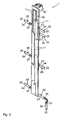
- Fig. 1 shows a view of a rewiring element 1 according to the invention in a perspective view from the front.
- Fig. 2 shows a perspective view of the same rewiring element 1 in a perspective view from behind.
- the rewiring element 1 of the first embodiment variant shown comprises a carrier 15 on which, by way of example, seven voltage taps 20 are arranged. At the upper end of the carrier 15, a plug 40 is provided.
- the carrier 15 is, for example, a printed circuit board made of FR4 or another printed circuit board material.
- a PorterzugDeutsch 10 is formed with a plurality of conductor tracks 11.
- the conductor tracks 11 extend at least in sections in the vertical direction from the plug 40 to the voltage taps 20 in order to establish an electrical path between them.
- the rewiring element 1 can be connected to a control unit of an energy storage module via the plug 40.
- the plug 40 is a component produced separately from the carrier 15, which can be produced, for example, by the encapsulation of contact elements with plastic. Likewise this can on any be made in another way.
- the preparation of the electrical connection between contact elements (not shown) of the plug 40 and the ends of the tracks 11 ending in the upper region of the carrier 15 can take place, for example, by means of a soldering process. Of course, other types of contacting are conceivable.
- each of the voltage taps 20 is electrically connected to at least one conductor track of the conductor traction structure of the carrier 15.
- the electrical connection is in each case in the region of a first end 21 of the voltage tap.
- Respective free, second ends 22 of the voltage taps are provided for material connection with associated cell connectors.
- the voltage taps 20 are designed as motion compensation elements. As a result, the voltage taps are able to compensate for a relative movement of the rewiring element relative to the cell connectors and / or due to different extensions of the rewiring element and the cell connectors and / or static or dynamic displacements of the memory cells of the energy storage module in which the rewiring element is used. This means that the voltage taps have an elasticity in all spatial directions (ie in the plane of the carrier 15 of the rewiring element 1 and perpendicular thereto), which on the one hand leads to no plastic deformation of the voltage taps and on the other hand the cohesive connection to the cell connectors and the connection to the Tracks are not mechanically stressed.
- FIGS. 1 and 2 show a way to provide this elastic motion compensation by means of the voltage taps 20 by their geometric shape.
- the first ends 21 of the voltage taps lie in a first connection section 23 and the second ends 22 of the voltage taps 20 in a second connection section 24.
- the first and the second connection section adjoin one another in the exemplary embodiment at a 90 ° angle.
- the selected angle is merely exemplary. Rather, the first and the second connection section 23, 24 could also be arranged at a different angle, preferably in the range from 45 ° to 135 °, to one another.
- the angled design allows a flexible movement of the carrier 15 and cell connectors both in the plane of the carrier 15 and perpendicular thereto.
- the arrangement of the second connection sections 24 of the number of voltage taps 20 is predetermined by the position and arrangement of the memory cell connectors and thus of the memory cells electrically interconnected by the memory cell connectors. If this is possible due to the circumstances, it is preferred if the first connection section 23 forms an extension of a respective contacted conductor track of the conductor traction structure (in the vertical). This is associated with an increased stability of the rewiring element, but also greater elasticity, since the free, movable length between the fixed first and second ends 21, 22 of the voltage taps 20 determines the flexibility.
- a further improved flexibility of the voltage taps 20 results from the provision of slots 26, 27 in the first and second connection sections 23, 24.
- the slots preferably merge into one another in the area of the angles.
- each of the terminal sections 23, 24 each have a single slot 26, 27.
- a plurality of thinner slots arranged parallel next to each other could also be provided in each connection section.
- the slots may be inserted into the voltage taps 20 by a separation method, such as e.g. Punching, be introduced. Likewise, it is possible to introduce slots by means of a laser in the voltage taps.
- the first and second terminal portions 23, 24 of respective voltage taps 20 are in the in the FIGS. 1 and 2 shown embodiment arranged in different, parallel planes. This results in a step profile of the voltage taps 20.
- the step profile can on the one hand by the geometric conditions in the connection of the rewiring element 1 with the cell connectors of the energy storage module be conditional.
- the stepped course can also be deliberately provided in order to further increase the free length between the fixed first and second ends 21, 22 of the voltage taps 20, whereby the flexibility is further advantageously improved.
- the first and the second terminal portion 23, 24 are arranged in the same plane, wherein a protruding from the plane of the terminal portions 23, 24 groove portion 28 is provided. This also extends the free length to improve flexibility between the fixed first and second ends 21, 22.
- a single groove is provided.
- the voltage tap could also have a plurality of adjacent grooves or waves.
- the grooves or shafts could protrude both downwardly and upwardly out of the plane of the first and second terminal portions 23, 24.
- the groove or grooves are preferably arranged in the second connection section. This makes it possible, on the one hand, for the first connection section 23 to extend at a small distance or adjacent to the carrier 15. On the other hand, this is due to the fact that the rewiring element 1 is arranged with its front side ahead of the memory cell module. In other words, the plug 40 points in the direction of the memory cells of the energy storage module. A groove section pointing in the direction of the plug and thus of the memory cells would require the presence of corresponding empty space. In principle, however, such a variant is possible.
- the voltage taps 20 copper or aluminum or an alloy thereof is preferably selected.
- the voltage taps may also be made of a different material and coated with copper or aluminum or alloys thereof.
- the material of the voltage taps is selected corresponding to the material of the cell connectors and / or the conductor tracks to be contacted, in which or regions a cohesive connection is to take place. If cell connectors and interconnects are made of different materials, the voltage taps could also be designed as a bimetal. In this case can be special simple way to achieve a material connection of the first and second ends 21, 22 of the voltage taps with the respective connection partners.
- the second ends 22 of the voltage taps are welded directly to the cell connector, or optionally directly to a connection terminal of the memory cell.
- the welding is done using a laser, but all other welding methods, such as e.g. Friction welding, ultrasonic welding, friction stir welding, torsional friction welding, rotational friction welding, multi-orbital friction welding, resistance welding, can be used.
- the voltage taps 20 are made of copper, they are provided with a conventional surface (tin). As a result, for example, a soldering in the reflow process can take place.
- the voltage taps 20 are made of aluminum, then a copper barrier layer and / or a nickel-tin surface is applied. Subsequently, in the manner described by inserting the feet through corresponding recesses of the circuit board 15 and a soldering.
- the number and arrangement of the voltage taps 20 on the carrier 15 is given by the number and shape of the memory connectors or of the connecting them Memory cells.
- at least one voltage tap is provided per cell connector.
- the function of a voltage attack is to transmit measurement currents so that measurement and control functions can be taken over by the control unit connected to the plug.
- the voltage taps are used to measure temperatures of the cell connectors and thus of the memory cells. In addition, these serve to measure voltages of the individual memory cells in order to achieve a voltage balance of the energy storage module.
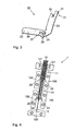
- Fig. 4 shows in a perspective view an alternative embodiment of a rewiring element 1.
- theauerzugDeutsch is not formed in and / or on a support, but realized by a stamped and bent element. Only schematically, individual, parallel in the vertical direction extending tracks 11 of Porterzug poetic 10 can be seen.
- the voltage taps 20 can be integrally formed with the conductor tracks 11 of the conductor traction structure 10.
- the voltage taps of the type described above may also be electrically connected to the tracks 11 of the ladder structure by welding or soldering or otherwise. From the schematic representation of Fig. 4 further shows that the second ends of the voltage taps 20 are electrically contacted on the not visible in the figure front of the cell connectors.
- five cell connectors 120 are contacted by the rewiring element 1, and two so-called module blades 121 are contacted via voltage taps 20 in the upper area, which are each electrically connected to a cell terminal of a memory cell.
- an electrical contacting of a respective energy storage module takes place from the outside.
- FIGS. 5 and 6 each show in a schematic plan view the structure of an energy storage module according to the invention once without memory cells ( Fig. 5 ) and once with memory cells ( Fig. 6 ).
- the energy storage module consists - by way of example only - two horizontally juxtaposed columns with six vertically stacked memory cells. Respect to the viewer in Fig. 6 facing cell terminals are arranged alternately one above the other and next to each other. This means that, for example, a positive pole of the memory cell 110 is arranged in the lower left in a plane with a negative pole of the memory cell 110 arranged vertically above it. Then in the vertical direction upwards again a positive pole, followed by a negative pole, etc.
- the positive pole of the memory cell 110 bottom left is arranged in a plane with a negative pole of the memory cell of the horizontally adjacent column (bottom right). In the vertical direction above this again followed by a positive pole, followed by a negative pole, etc.
- a cell connector connects a plus and a minus pole adjacent memory cells 110.
- the energy storage module 100 has five cell connectors 120.
- the two uppermost memory cells 110 in the vertical direction are connected to the already mentioned module blades 121, via which a total voltage of the energy storage module can be tapped.
- the rewiring element 1 is arranged between the two vertically arranged columns.
- the viewer is in the Fig. 2 shown facing back of the rewiring element 1.
- the electrical contacting of the voltage taps 20 takes place on the sides of the cell connectors 120 facing the viewer, including the module blades 121 or, if appropriate, of the respective cell terminals of the memory cells themselves.
- FIGS. 1 and 2 apparent plug has away from the viewer in the leaf level and is thus facing the memory cells. As a result, a space-optimized energy storage module 100 is provided.
- a mechanical fixation of the rewiring element 1 is preferably carried out not only via the cohesive connections to the cell connectors / Modulglotem or memory cells, but it is additionally a holder in a holding element 102, not shown.
- the production of the integral connection between cell terminals and cell connectors is preferably carried out by a welding process, wherein preferably laser welding is used. In addition, however, other welding methods can be used.
Landscapes
- Chemical & Material Sciences (AREA)
- Chemical Kinetics & Catalysis (AREA)
- Electrochemistry (AREA)
- General Chemical & Material Sciences (AREA)
- Engineering & Computer Science (AREA)
- Manufacturing & Machinery (AREA)
- Microelectronics & Electronic Packaging (AREA)
- Metallurgy (AREA)
- Semiconductor Memories (AREA)
- Connection Of Batteries Or Terminals (AREA)
- Battery Mounting, Suspending (AREA)
Claims (7)
- Elément de câblage (1) de module accumulateur d'énergie destiné à un module accumulateur d'énergie (100) qui est constitué de plusieurs cellules d'accumulation (110) positionnées les unes au-dessus des autres selon au moins une rangée verticale qui sont reliées électriquement entre elles par paires par l'intermédiaire d'un élément de liaison de cellules (120), comportant :- une structure de lignes conductrices (10) comportant plusieurs pistes conductrices (11) positionnées côte à côte et s'étendant verticalement,- plusieurs prises de tension (20) dont les premières extrémités (21) tournées vers les pistes conductrices (11) sont respectivement reliées avec une première extrémité (12) associée d'une piste conductrice (11) respective, et dont les secondes extrémités (22) libres sont prévues pour permettre une liaison par la matière avec des éléments de liaison de cellules (120) associés, les prises de tension (20) et les structures de lignes conductrices (10) étant coplanaires ou positionnées dans des plans s'étendant parallèlement, et, les premières extrémités (21) des prises de tension (20) étant situées dans un premier tronçon de liaison (23) tandis que les secondes extrémités (22) des prises de tension (20) sont situées dans un second tronçon de liaison (24), le premier et le second tronçon de liaison (24) étant voisins, et, pour au moins certaines des prises de tension (20) le premier tronçon de liaison (23) étant disposé sous un angle de 45° à 135°, en particulier de 90° par rapport au second tronçon de liaison (24),caractérisé en ce que
les prises de tension (20) sont réalisées sous la forme d'éléments de compensation de déplacement flexibles pour pouvoir compenser, lors du fonctionnement du module accumulateur d'énergie un déplacement relatif de l'élément de câblage (1) par rapport aux éléments de liaison des cellules (120), et/ou des différences de dilatation de l'élément de câblage (1) et de l'élément de liaison de cellules (120), à cet effet :- le premier et le second tronçon de liaison (24) étant équipés de fentes (26, 27) situées en continuité les unes par rapport aux autres, et/ou- au moins certaines des prises de tension (20) comportant un tronçon à rainures (28) dépassant du plan de la prise de tension (20) concernée. - Elément de câblage de module accumulateur d'énergie conforme à la revendication 1,
caractérisé en ce que
la structure de lignes conductrices (10) est réalisée dans et/ou sur une plaque support (15). - Elément de câblage de module accumulateur d'énergie conforme à la revendication 2,
caractérisé en ce que
les premières extrémités (21) des prises de tension (20) comportent au moins un talon (30, 31) dépassant du plan de la prise de tension (20) concernée, qui est enfiché au travers d'évidements associés de la plaque-support (15). - Elément de câblage de module accumulateur d'énergie conforme à la revendication 1,
caractérisé en ce que
les prises de tension (20) et la structure de lignes conductrices (10) sont réalisées en une seule pièce. - Procédé d'obtention d'un élément de câblage de module accumulateur d'énergie (1) conforme à l'une des revendications précédentes destiné à un module accumulateur d'énergie (100) qui est constitué de plusieurs cellules d'accumulation (110) positionnées les unes au-dessus des autres selon au moins une rangée verticale et qui sont électriquement reliées entre elles par paires par l'intermédiaire d'un élément de liaison de cellules (120), comportant les étapes constant à :- fabriquer une structure de lignes conductrices (10) comportant plusieurs pistes conductrices (11),- fabriquer plusieurs prises de tension (20) de sorte que celles-ci puissent, en tant qu'élément de compensation de déplacement flexible, lors du fonctionnement du module d'accumulation d'énergie, compenser un déplacement relatif de l'élément de câblage (1) vis-à-vis des éléments de liaison (120) des cellules et/ou des différences de dilatation de l'élément de câblage (1) et de l'élément de liaison de cellules (120), à cet effet, des premières extrémités (21) des prises de tension (20) étant situées dans un premier tronçon de liaison (23) tandis que les secondes extrémités (22) des prises de tension (20) sont situées dans un second tronçon de liaison (24), le premier et le second tronçon de liaison (24) étant voisins l'un de l'autre, et, pour au moins certaines des prises de tension (20) le premier tronçon de liaison (23) étant positionné sous un angle de 45° à 135°, en particulier de 90° par rapport au second tronçon de liaison (24) et en outre, le premier et le second tronçon de liaison (24) étant équipés de fentes (26, 27) se prolongeant les unes dans les autres, et/ou au moins certaines des prises de tension (20) comportant au moins un tronçon (28) à rainures dépassant du plan de la prise de tension (20) respective,- liaison respective par la matière des prises de tension (20) à leurs premières extrémités (21) tournées vers les pistes conductrices (11) avec une première extrémité associée d'une piste conductrice (11) respective, les prises de tension (20) et la structure de lignes conductrices (10) étant coplanaires ou étant positionnées dans des plans s'étendant parallèlement.
- Module accumulateur d'énergie (100) en particulier destiné à des véhicules comprenant :- plusieurs cellules d'accumulation (110) positionnées les unes au-dessus des autres selon au moins une rangée verticale et qui sont reliées électriquement par paires les unes aux autres par un élément de liaison de cellules (120),- un élément de câblage de module accumulateur d'énergie (1), caractérisé en ce que l'élément de câblage de module accumulateur d'énergie (1) est réalisé conformément à l'une quelconque des revendications 1 à 4,les secondes extrémités libres (22) des prises de tension (20) étant reliées par une liaison par la matière aux éléments de liaison de cellules (120) associés.
- Procédé d'obtention d'un module accumulateur d'énergie (100) comportant les étapes consistant à :- fabriquer un élément de câblage de module accumulateur d'énergie (1) conforme à l'une des revendications 1 à 4,- fabriquer un module accumulateur d'énergie (100) comportant plusieurs cellules d'accumulation (110) positionnées les unes au-dessus des autres sur au moins une rangée verticale et qui sont reliées électriquement les unes aux autres par paires par un élément de liaison de cellules (120),- fabriquer une liaison par la matière des secondes extrémités libres (22) des prises de tension (20) avec des éléments de liaison de cellules (120) associés en utilisant un appareil de soudage laser.
Applications Claiming Priority (2)
| Application Number | Priority Date | Filing Date | Title |
|---|---|---|---|
| DE102010022689A DE102010022689A1 (de) | 2010-06-04 | 2010-06-04 | Umverdrahtungselement für ein Energiespeichermodul, Verfahren zu dessen Herstellung und Energiespeichermodul |
| PCT/EP2011/002370 WO2011157331A1 (fr) | 2010-06-04 | 2011-05-13 | Elément de câblage pour un module de stockage d'énergie, procédé de fabrication dudit élément de câblage et module de stockage d'énergie |
Publications (2)
| Publication Number | Publication Date |
|---|---|
| EP2577773A1 EP2577773A1 (fr) | 2013-04-10 |
| EP2577773B1 true EP2577773B1 (fr) | 2014-08-20 |
Family
ID=44118776
Family Applications (1)
| Application Number | Title | Priority Date | Filing Date |
|---|---|---|---|
| EP11721434.6A Active EP2577773B1 (fr) | 2010-06-04 | 2011-05-13 | Elément de câblage pour un module de stockage d'énergie, procédé de fabrication dudit élément de câblage et module de stockage d'énergie |
Country Status (4)
| Country | Link |
|---|---|
| EP (1) | EP2577773B1 (fr) |
| CN (1) | CN102859755B (fr) |
| DE (1) | DE102010022689A1 (fr) |
| WO (1) | WO2011157331A1 (fr) |
Families Citing this family (14)
| Publication number | Priority date | Publication date | Assignee | Title |
|---|---|---|---|---|
| EP2605028A1 (fr) * | 2011-12-13 | 2013-06-19 | Magna E-Car Systems GmbH & Co OG | Dispositif de surveillance de la tension de cellules de batterie |
| DE102012202623A1 (de) * | 2012-02-21 | 2013-08-22 | Elringklinger Ag | Zellverbinder |
| EP2658034A1 (fr) | 2012-04-27 | 2013-10-30 | Magna E-Car Systems GmbH & Co OG | Élément de prise de tension, unité de surveillance de cellules, unité de batterie et leurs procédés de fabrication |
| DE102012011607B4 (de) * | 2012-06-12 | 2021-09-23 | Volkswagen Aktiengesellschaft | Verbindereinheit zum Kontaktieren elektrischer Speicherzellen, Verfahren zum Herstellen einer solchen Verbindereinheit und Akkumulatorenbatterie mit der Verbindereinheit |
| DE102012213673A1 (de) | 2012-08-02 | 2014-02-06 | Robert Bosch Gmbh | Batteriemodul sowie Batterie und Kraftfahrzeug umfassend ein solches |
| EP2765628A1 (fr) * | 2013-02-07 | 2014-08-13 | MAGNA STEYR Battery Systems GmbH & Co OG | Système de batterie et procédé de fabrication d'un système de batterie |
| DE102013213848A1 (de) | 2013-07-16 | 2015-01-22 | Robert Bosch Gmbh | Abdeckung für Batterien |
| DE102013222090A1 (de) * | 2013-10-30 | 2015-04-30 | Volkswagen Aktiengesellschaft | Zellkontaktierungssystem, Batteriemodul mit einem Zellkontaktierungssystem und Fahrzeug mit zumindest einem derartigen Batteriemodul |
| CN106463791B (zh) * | 2014-06-26 | 2021-06-04 | 罗伯特·博世有限公司 | 用于将电信号从至少一个电池传递到至少一个电子分析单元的传递设备 |
| DE102017222883A1 (de) * | 2017-12-15 | 2019-06-19 | Te Connectivity Germany Gmbh | Kontaktierungseinheit zum elektrischen Kontaktieren zumindest eines Elektroniksegments eines Elektronikmoduls und Verfahren |
| DE102018206231B3 (de) | 2018-04-23 | 2019-09-19 | Triathlon Batterien Gmbh | Vorrichtung zum elektrischen Kontaktieren einer Leiterplatte an ein Batteriezellenverbundsystem und Einrichtung mit einer derartigen Vorrichtung und einem derartigen Batteriezellenverbundsystem |
| CN110690401B (zh) * | 2018-07-05 | 2022-07-05 | 东莞新能源科技有限公司 | 电池结构、电池及其制备方法 |
| DE102018212710A1 (de) * | 2018-07-31 | 2020-02-06 | Robert Bosch Gmbh | Elektrischer Energiespeicher, Vorrichtung und/oder Fahrzeug und Verfahren zur Herstellung eines elektrischen Energiespeichers |
| DE102023110783A1 (de) * | 2023-04-26 | 2024-10-31 | Yazaki Systems Technologies Gmbh | Verbindungssystem für einen elektrischen Energiespeicher eines Fahrzeugs, elektrischer Energiespeicher und Verfahren zur Herstellung des Verbindungssystems |
Citations (1)
| Publication number | Priority date | Publication date | Assignee | Title |
|---|---|---|---|---|
| DE19847145A1 (de) * | 1997-10-13 | 1999-05-06 | Toyota Motor Co Ltd | Verbindungsplatte für einen Batteriehalter |
Family Cites Families (7)
| Publication number | Priority date | Publication date | Assignee | Title |
|---|---|---|---|---|
| US5618187A (en) * | 1994-11-17 | 1997-04-08 | The Whitaker Corporation | Board mount bus bar contact |
| DE19810746B4 (de) * | 1998-03-12 | 2008-10-16 | Varta Automotive Systems Gmbh | Platine mit einer Schaltung zur Überwachung einer mehrzelligen Akkumulatorenbatterie |
| DE10134143A1 (de) * | 2001-07-13 | 2003-01-30 | Daimler Chrysler Ag | System zur Verschaltung von Schwachstromkomponenten mit Zellen in Hochleitstungsstromquellen |
| EP2193563A1 (fr) * | 2007-09-27 | 2010-06-09 | Kabushiki Kaisha Toshiba | Barre omnibus |
| CN102197509B (zh) * | 2008-09-09 | 2014-11-26 | 江森自控帅福得先进能源动力系统有限责任公司 | 用于电池组件的互连垫圈组件 |
| DE202009012647U1 (de) | 2009-09-21 | 2009-11-26 | Auto-Kabel Managementgesellschaft Mbh | Batteriezellenverbinder |
| DE102009058632A1 (de) * | 2009-12-16 | 2011-06-22 | Carl Freudenberg KG, 69469 | Busbarplatte |
-
2010
- 2010-06-04 DE DE102010022689A patent/DE102010022689A1/de not_active Withdrawn
-
2011
- 2011-05-13 EP EP11721434.6A patent/EP2577773B1/fr active Active
- 2011-05-13 CN CN201180019461.8A patent/CN102859755B/zh active Active
- 2011-05-13 WO PCT/EP2011/002370 patent/WO2011157331A1/fr not_active Ceased
Patent Citations (1)
| Publication number | Priority date | Publication date | Assignee | Title |
|---|---|---|---|---|
| DE19847145A1 (de) * | 1997-10-13 | 1999-05-06 | Toyota Motor Co Ltd | Verbindungsplatte für einen Batteriehalter |
Also Published As
| Publication number | Publication date |
|---|---|
| CN102859755A (zh) | 2013-01-02 |
| DE102010022689A1 (de) | 2011-12-08 |
| CN102859755B (zh) | 2015-04-15 |
| WO2011157331A1 (fr) | 2011-12-22 |
| EP2577773A1 (fr) | 2013-04-10 |
Similar Documents
| Publication | Publication Date | Title |
|---|---|---|
| WO2011157331A1 (fr) | Elément de câblage pour un module de stockage d'énergie, procédé de fabrication dudit élément de câblage et module de stockage d'énergie | |
| EP3200261B1 (fr) | Système de mise en contact pour des éléments d'accumulateur d'énergie et accumulateur d'énergie | |
| EP3350851B1 (fr) | Module de batterie, son procédé de fabrication ainsi que batterie | |
| DE102012101771A1 (de) | Klemmenanschlusseinrichtung für einenergiespeichermodul | |
| DE102009050315A1 (de) | Verbindungsvorrichtung | |
| DE102010019708A1 (de) | Speicherzellenverbinder und Speichermodul | |
| WO2012022438A1 (fr) | Élément de câblage pour un module de stockage d'énergie et module de stockage d'énergie | |
| DE102012005120A1 (de) | Verbindungssystem für eine Energiespeichereinrichtung und Energiespeichereinrichtung mit dem Verbindungssystem | |
| EP2497134B1 (fr) | Procédé pour relier un pôle de batterie au niveau d'un premier élément de batterie à un pôle de batterie au niveau d'un second élément de batterie, batterie constituée d'éléments de batterie reliés entre eux et système de batteries | |
| WO2012130424A1 (fr) | Batterie pour véhicule automobile | |
| DE102007020295A1 (de) | Vorrichtung zum Speichern von elektrischer Energie | |
| WO2015197319A1 (fr) | Dispositif de transmission pour transmettre des signaux électriques d'au moins une cellule galvanique à au moins une unité d'évaluation électronique | |
| DE102012215205A1 (de) | Zellenverbinder, Batteriezellenmodul, Batterie, Verfahren zur Herstellung eines Batteriezellenmoduls und Kraftfahrzeug | |
| DE102018214363A1 (de) | Stromschiene, stromschienenmodul und batteriepack | |
| WO2022096207A1 (fr) | Dispositif de contact d'élément de batterie et module de batterie comprenant un tel dispositif de contact d'élément de batterie | |
| DE102015007615A1 (de) | Verbindungselement zur elektrischen Verschaltung von Einzelzellen, Zellblock und elektrische Batterie | |
| EP2658034A1 (fr) | Élément de prise de tension, unité de surveillance de cellules, unité de batterie et leurs procédés de fabrication | |
| DE102022103508A1 (de) | Zellkontaktiersystem | |
| WO2013139517A1 (fr) | Dispositif de connexion pour connecter des composants électriques d'un accumulateur d'énergie électrique, accumulateur d'énergie électrique et procédé pour connecter des composants électriques d'un accumulateur d'énergie électrique | |
| DE102009050319B4 (de) | Elektrochemische Vorrichtung | |
| EP2524407B1 (fr) | Batterie, système de batteries et procédé de connexion d'une pluralité de batteries | |
| EP4084202A1 (fr) | Agencement de connecteur d'élément de batterie, module de batterie, dispositif batterie pourvu d'au moins deux modules de batterie et procédé de fabrication du dispositif batterie | |
| EP2956976B1 (fr) | Élément de connexion d'éléments servant à relier de manière électriquement conductrice une pluralité de bornes d'éléments de batterie, procédé de fabrication d'un tel élément de connexion d'éléments et bloc batterie comprenant au moins un tel élément de connexion d'éléments | |
| DE202018106448U1 (de) | Deckel für ein Batteriemodul, Batteriemodulanordnung und Batterie | |
| DE102024136148B3 (de) | Batteriepack mit lösbarem Elektronikmodul |
Legal Events
| Date | Code | Title | Description |
|---|---|---|---|
| PUAI | Public reference made under article 153(3) epc to a published international application that has entered the european phase |
Free format text: ORIGINAL CODE: 0009012 |
|
| 17P | Request for examination filed |
Effective date: 20121030 |
|
| AK | Designated contracting states |
Kind code of ref document: A1 Designated state(s): AL AT BE BG CH CY CZ DE DK EE ES FI FR GB GR HR HU IE IS IT LI LT LU LV MC MK MT NL NO PL PT RO RS SE SI SK SM TR |
|
| DAX | Request for extension of the european patent (deleted) | ||
| 17Q | First examination report despatched |
Effective date: 20131104 |
|
| GRAP | Despatch of communication of intention to grant a patent |
Free format text: ORIGINAL CODE: EPIDOSNIGR1 |
|
| INTG | Intention to grant announced |
Effective date: 20140422 |
|
| GRAP | Despatch of communication of intention to grant a patent |
Free format text: ORIGINAL CODE: EPIDOSNIGR1 |
|
| INTG | Intention to grant announced |
Effective date: 20140603 |
|
| GRAS | Grant fee paid |
Free format text: ORIGINAL CODE: EPIDOSNIGR3 |
|
| GRAA | (expected) grant |
Free format text: ORIGINAL CODE: 0009210 |
|
| AK | Designated contracting states |
Kind code of ref document: B1 Designated state(s): AL AT BE BG CH CY CZ DE DK EE ES FI FR GB GR HR HU IE IS IT LI LT LU LV MC MK MT NL NO PL PT RO RS SE SI SK SM TR |
|
| REG | Reference to a national code |
Ref country code: GB Ref legal event code: FG4D Free format text: NOT ENGLISH |
|
| REG | Reference to a national code |
Ref country code: CH Ref legal event code: EP |
|
| REG | Reference to a national code |
Ref country code: AT Ref legal event code: REF Ref document number: 683871 Country of ref document: AT Kind code of ref document: T Effective date: 20140915 |
|
| REG | Reference to a national code |
Ref country code: IE Ref legal event code: FG4D Free format text: LANGUAGE OF EP DOCUMENT: GERMAN |
|
| REG | Reference to a national code |
Ref country code: DE Ref legal event code: R096 Ref document number: 502011004114 Country of ref document: DE Effective date: 20141002 |
|
| REG | Reference to a national code |
Ref country code: NL Ref legal event code: VDEP Effective date: 20140820 |
|
| REG | Reference to a national code |
Ref country code: LT Ref legal event code: MG4D |
|
| PG25 | Lapsed in a contracting state [announced via postgrant information from national office to epo] |
Ref country code: SE Free format text: LAPSE BECAUSE OF FAILURE TO SUBMIT A TRANSLATION OF THE DESCRIPTION OR TO PAY THE FEE WITHIN THE PRESCRIBED TIME-LIMIT Effective date: 20140820 Ref country code: LT Free format text: LAPSE BECAUSE OF FAILURE TO SUBMIT A TRANSLATION OF THE DESCRIPTION OR TO PAY THE FEE WITHIN THE PRESCRIBED TIME-LIMIT Effective date: 20140820 Ref country code: GR Free format text: LAPSE BECAUSE OF FAILURE TO SUBMIT A TRANSLATION OF THE DESCRIPTION OR TO PAY THE FEE WITHIN THE PRESCRIBED TIME-LIMIT Effective date: 20141121 Ref country code: FI Free format text: LAPSE BECAUSE OF FAILURE TO SUBMIT A TRANSLATION OF THE DESCRIPTION OR TO PAY THE FEE WITHIN THE PRESCRIBED TIME-LIMIT Effective date: 20140820 Ref country code: BG Free format text: LAPSE BECAUSE OF FAILURE TO SUBMIT A TRANSLATION OF THE DESCRIPTION OR TO PAY THE FEE WITHIN THE PRESCRIBED TIME-LIMIT Effective date: 20141120 Ref country code: NO Free format text: LAPSE BECAUSE OF FAILURE TO SUBMIT A TRANSLATION OF THE DESCRIPTION OR TO PAY THE FEE WITHIN THE PRESCRIBED TIME-LIMIT Effective date: 20141120 Ref country code: ES Free format text: LAPSE BECAUSE OF FAILURE TO SUBMIT A TRANSLATION OF THE DESCRIPTION OR TO PAY THE FEE WITHIN THE PRESCRIBED TIME-LIMIT Effective date: 20140820 Ref country code: PT Free format text: LAPSE BECAUSE OF FAILURE TO SUBMIT A TRANSLATION OF THE DESCRIPTION OR TO PAY THE FEE WITHIN THE PRESCRIBED TIME-LIMIT Effective date: 20141222 |
|
| PG25 | Lapsed in a contracting state [announced via postgrant information from national office to epo] |
Ref country code: IS Free format text: LAPSE BECAUSE OF FAILURE TO SUBMIT A TRANSLATION OF THE DESCRIPTION OR TO PAY THE FEE WITHIN THE PRESCRIBED TIME-LIMIT Effective date: 20141220 Ref country code: LV Free format text: LAPSE BECAUSE OF FAILURE TO SUBMIT A TRANSLATION OF THE DESCRIPTION OR TO PAY THE FEE WITHIN THE PRESCRIBED TIME-LIMIT Effective date: 20140820 Ref country code: RS Free format text: LAPSE BECAUSE OF FAILURE TO SUBMIT A TRANSLATION OF THE DESCRIPTION OR TO PAY THE FEE WITHIN THE PRESCRIBED TIME-LIMIT Effective date: 20140820 Ref country code: HR Free format text: LAPSE BECAUSE OF FAILURE TO SUBMIT A TRANSLATION OF THE DESCRIPTION OR TO PAY THE FEE WITHIN THE PRESCRIBED TIME-LIMIT Effective date: 20140820 |
|
| PG25 | Lapsed in a contracting state [announced via postgrant information from national office to epo] |
Ref country code: NL Free format text: LAPSE BECAUSE OF FAILURE TO SUBMIT A TRANSLATION OF THE DESCRIPTION OR TO PAY THE FEE WITHIN THE PRESCRIBED TIME-LIMIT Effective date: 20140820 |
|
| PG25 | Lapsed in a contracting state [announced via postgrant information from national office to epo] |
Ref country code: RO Free format text: LAPSE BECAUSE OF FAILURE TO SUBMIT A TRANSLATION OF THE DESCRIPTION OR TO PAY THE FEE WITHIN THE PRESCRIBED TIME-LIMIT Effective date: 20140820 Ref country code: DK Free format text: LAPSE BECAUSE OF FAILURE TO SUBMIT A TRANSLATION OF THE DESCRIPTION OR TO PAY THE FEE WITHIN THE PRESCRIBED TIME-LIMIT Effective date: 20140820 Ref country code: EE Free format text: LAPSE BECAUSE OF FAILURE TO SUBMIT A TRANSLATION OF THE DESCRIPTION OR TO PAY THE FEE WITHIN THE PRESCRIBED TIME-LIMIT Effective date: 20140820 Ref country code: SK Free format text: LAPSE BECAUSE OF FAILURE TO SUBMIT A TRANSLATION OF THE DESCRIPTION OR TO PAY THE FEE WITHIN THE PRESCRIBED TIME-LIMIT Effective date: 20140820 Ref country code: CZ Free format text: LAPSE BECAUSE OF FAILURE TO SUBMIT A TRANSLATION OF THE DESCRIPTION OR TO PAY THE FEE WITHIN THE PRESCRIBED TIME-LIMIT Effective date: 20140820 |
|
| REG | Reference to a national code |
Ref country code: DE Ref legal event code: R097 Ref document number: 502011004114 Country of ref document: DE |
|
| PG25 | Lapsed in a contracting state [announced via postgrant information from national office to epo] |
Ref country code: PL Free format text: LAPSE BECAUSE OF FAILURE TO SUBMIT A TRANSLATION OF THE DESCRIPTION OR TO PAY THE FEE WITHIN THE PRESCRIBED TIME-LIMIT Effective date: 20140820 |
|
| PLBE | No opposition filed within time limit |
Free format text: ORIGINAL CODE: 0009261 |
|
| STAA | Information on the status of an ep patent application or granted ep patent |
Free format text: STATUS: NO OPPOSITION FILED WITHIN TIME LIMIT |
|
| 26N | No opposition filed |
Effective date: 20150521 |
|
| PG25 | Lapsed in a contracting state [announced via postgrant information from national office to epo] |
Ref country code: SI Free format text: LAPSE BECAUSE OF FAILURE TO SUBMIT A TRANSLATION OF THE DESCRIPTION OR TO PAY THE FEE WITHIN THE PRESCRIBED TIME-LIMIT Effective date: 20140820 |
|
| REG | Reference to a national code |
Ref country code: CH Ref legal event code: PL |
|
| PG25 | Lapsed in a contracting state [announced via postgrant information from national office to epo] |
Ref country code: LU Free format text: LAPSE BECAUSE OF FAILURE TO SUBMIT A TRANSLATION OF THE DESCRIPTION OR TO PAY THE FEE WITHIN THE PRESCRIBED TIME-LIMIT Effective date: 20150513 Ref country code: CH Free format text: LAPSE BECAUSE OF NON-PAYMENT OF DUE FEES Effective date: 20150531 Ref country code: LI Free format text: LAPSE BECAUSE OF NON-PAYMENT OF DUE FEES Effective date: 20150531 Ref country code: MC Free format text: LAPSE BECAUSE OF FAILURE TO SUBMIT A TRANSLATION OF THE DESCRIPTION OR TO PAY THE FEE WITHIN THE PRESCRIBED TIME-LIMIT Effective date: 20140820 |
|
| REG | Reference to a national code |
Ref country code: IE Ref legal event code: MM4A |
|
| PG25 | Lapsed in a contracting state [announced via postgrant information from national office to epo] |
Ref country code: IE Free format text: LAPSE BECAUSE OF NON-PAYMENT OF DUE FEES Effective date: 20150513 |
|
| REG | Reference to a national code |
Ref country code: FR Ref legal event code: PLFP Year of fee payment: 6 |
|
| PG25 | Lapsed in a contracting state [announced via postgrant information from national office to epo] |
Ref country code: MT Free format text: LAPSE BECAUSE OF FAILURE TO SUBMIT A TRANSLATION OF THE DESCRIPTION OR TO PAY THE FEE WITHIN THE PRESCRIBED TIME-LIMIT Effective date: 20140820 |
|
| REG | Reference to a national code |
Ref country code: FR Ref legal event code: PLFP Year of fee payment: 7 |
|
| PG25 | Lapsed in a contracting state [announced via postgrant information from national office to epo] |
Ref country code: HU Free format text: LAPSE BECAUSE OF FAILURE TO SUBMIT A TRANSLATION OF THE DESCRIPTION OR TO PAY THE FEE WITHIN THE PRESCRIBED TIME-LIMIT; INVALID AB INITIO Effective date: 20110513 Ref country code: SM Free format text: LAPSE BECAUSE OF FAILURE TO SUBMIT A TRANSLATION OF THE DESCRIPTION OR TO PAY THE FEE WITHIN THE PRESCRIBED TIME-LIMIT Effective date: 20140820 |
|
| PG25 | Lapsed in a contracting state [announced via postgrant information from national office to epo] |
Ref country code: CY Free format text: LAPSE BECAUSE OF FAILURE TO SUBMIT A TRANSLATION OF THE DESCRIPTION OR TO PAY THE FEE WITHIN THE PRESCRIBED TIME-LIMIT Effective date: 20140820 |
|
| REG | Reference to a national code |
Ref country code: AT Ref legal event code: MM01 Ref document number: 683871 Country of ref document: AT Kind code of ref document: T Effective date: 20160513 |
|
| PG25 | Lapsed in a contracting state [announced via postgrant information from national office to epo] |
Ref country code: BE Free format text: LAPSE BECAUSE OF NON-PAYMENT OF DUE FEES Effective date: 20150531 |
|
| PG25 | Lapsed in a contracting state [announced via postgrant information from national office to epo] |
Ref country code: AT Free format text: LAPSE BECAUSE OF NON-PAYMENT OF DUE FEES Effective date: 20160513 Ref country code: TR Free format text: LAPSE BECAUSE OF FAILURE TO SUBMIT A TRANSLATION OF THE DESCRIPTION OR TO PAY THE FEE WITHIN THE PRESCRIBED TIME-LIMIT Effective date: 20140820 |
|
| REG | Reference to a national code |
Ref country code: FR Ref legal event code: PLFP Year of fee payment: 8 |
|
| PG25 | Lapsed in a contracting state [announced via postgrant information from national office to epo] |
Ref country code: MK Free format text: LAPSE BECAUSE OF FAILURE TO SUBMIT A TRANSLATION OF THE DESCRIPTION OR TO PAY THE FEE WITHIN THE PRESCRIBED TIME-LIMIT Effective date: 20140820 |
|
| PG25 | Lapsed in a contracting state [announced via postgrant information from national office to epo] |
Ref country code: AL Free format text: LAPSE BECAUSE OF FAILURE TO SUBMIT A TRANSLATION OF THE DESCRIPTION OR TO PAY THE FEE WITHIN THE PRESCRIBED TIME-LIMIT Effective date: 20140820 |
|
| REG | Reference to a national code |
Ref country code: DE Ref legal event code: R079 Ref document number: 502011004114 Country of ref document: DE Free format text: PREVIOUS MAIN CLASS: H01M0002200000 Ipc: H01M0050500000 |
|
| P01 | Opt-out of the competence of the unified patent court (upc) registered |
Effective date: 20230503 |
|
| PGFP | Annual fee paid to national office [announced via postgrant information from national office to epo] |
Ref country code: DE Payment date: 20250512 Year of fee payment: 15 |
|
| PGFP | Annual fee paid to national office [announced via postgrant information from national office to epo] |
Ref country code: GB Payment date: 20250522 Year of fee payment: 15 |
|
| PGFP | Annual fee paid to national office [announced via postgrant information from national office to epo] |
Ref country code: IT Payment date: 20250530 Year of fee payment: 15 |
|
| PGFP | Annual fee paid to national office [announced via postgrant information from national office to epo] |
Ref country code: FR Payment date: 20250521 Year of fee payment: 15 |