EP2578358B1 - Schleifmaschine und Verfahren zur Innenbearbeitung von Kokillen - Google Patents
Schleifmaschine und Verfahren zur Innenbearbeitung von Kokillen Download PDFInfo
- Publication number
- EP2578358B1 EP2578358B1 EP12182794.3A EP12182794A EP2578358B1 EP 2578358 B1 EP2578358 B1 EP 2578358B1 EP 12182794 A EP12182794 A EP 12182794A EP 2578358 B1 EP2578358 B1 EP 2578358B1
- Authority
- EP
- European Patent Office
- Prior art keywords
- grinding
- unit
- grinding machine
- mold
- radial inner
- Prior art date
- Legal status (The legal status is an assumption and is not a legal conclusion. Google has not performed a legal analysis and makes no representation as to the accuracy of the status listed.)
- Active
Links
- 238000000034 method Methods 0.000 title claims description 12
- 238000012545 processing Methods 0.000 title description 6
- 238000003754 machining Methods 0.000 claims description 15
- 230000008878 coupling Effects 0.000 claims description 4
- 238000010168 coupling process Methods 0.000 claims description 4
- 238000005859 coupling reaction Methods 0.000 claims description 4
- 239000000463 material Substances 0.000 description 4
- 229910000831 Steel Inorganic materials 0.000 description 3
- 238000003825 pressing Methods 0.000 description 3
- 239000010959 steel Substances 0.000 description 3
- 230000008901 benefit Effects 0.000 description 2
- 238000005266 casting Methods 0.000 description 2
- 238000005259 measurement Methods 0.000 description 2
- 229910001208 Crucible steel Inorganic materials 0.000 description 1
- 229910001141 Ductile iron Inorganic materials 0.000 description 1
- 230000002411 adverse Effects 0.000 description 1
- 230000015572 biosynthetic process Effects 0.000 description 1
- 238000009530 blood pressure measurement Methods 0.000 description 1
- 230000001680 brushing effect Effects 0.000 description 1
- 230000008859 change Effects 0.000 description 1
- 230000001419 dependent effect Effects 0.000 description 1
- 238000001514 detection method Methods 0.000 description 1
- 239000012535 impurity Substances 0.000 description 1
- 239000007788 liquid Substances 0.000 description 1
- 238000004519 manufacturing process Methods 0.000 description 1
- 238000012805 post-processing Methods 0.000 description 1
- 230000008569 process Effects 0.000 description 1
- 230000009467 reduction Effects 0.000 description 1
- 238000005096 rolling process Methods 0.000 description 1
Images


Classifications
-
- B—PERFORMING OPERATIONS; TRANSPORTING
- B24—GRINDING; POLISHING
- B24B—MACHINES, DEVICES, OR PROCESSES FOR GRINDING OR POLISHING; DRESSING OR CONDITIONING OF ABRADING SURFACES; FEEDING OF GRINDING, POLISHING, OR LAPPING AGENTS
- B24B27/00—Other grinding machines or devices
- B24B27/033—Other grinding machines or devices for grinding a surface for cleaning purposes, e.g. for descaling or for grinding off flaws in the surface
- B24B27/04—Grinding machines or devices in which the grinding tool is supported on a swinging arm
-
- B—PERFORMING OPERATIONS; TRANSPORTING
- B24—GRINDING; POLISHING
- B24B—MACHINES, DEVICES, OR PROCESSES FOR GRINDING OR POLISHING; DRESSING OR CONDITIONING OF ABRADING SURFACES; FEEDING OF GRINDING, POLISHING, OR LAPPING AGENTS
- B24B19/00—Single-purpose machines or devices for particular grinding operations not covered by any other main group
- B24B19/20—Single-purpose machines or devices for particular grinding operations not covered by any other main group for grinding dies
-
- B—PERFORMING OPERATIONS; TRANSPORTING
- B24—GRINDING; POLISHING
- B24B—MACHINES, DEVICES, OR PROCESSES FOR GRINDING OR POLISHING; DRESSING OR CONDITIONING OF ABRADING SURFACES; FEEDING OF GRINDING, POLISHING, OR LAPPING AGENTS
- B24B27/00—Other grinding machines or devices
- B24B27/0038—Other grinding machines or devices with the grinding tool mounted at the end of a set of bars
Definitions
- the invention relates to a grinding machine and a method for internal machining of molds, such as known from the document DE 84 06 650 U1 wherein the grinding machine comprises a positioning device and a grinding device, the grinding device being disposed at one end of an arm of the positioning device and positionable relative to a radially inner surface of a mold by means of the positioning device, the grinding device comprising a motor-driven grinding device for machining the radially inner surface of the mold having.
- Chill molds for cast steel have a geometrically simple shape, for example a round or rectangular ring shape, and are usually made of nodular cast iron.
- undesirable impurities which reduce a quality of a surface of a steel block in a row.
- by a high temperature difference between the radially inner surface of the mold and an outer surface during or after pouring liquid steel occurs in the corner regions of the Mold to stress cracks, which also adversely affect the surface quality of a block.
- the present invention is therefore based on the object to provide a grinding machine and a method for internal machining of molds, which allows a simplified machining and thus a faster and cheaper grinding a radial inner surface of a mold.
- the grinding machine for internal machining of molds comprises a positioning device and a grinding device, wherein the grinding device is arranged at one end of an arm of the positioning and positionable by means of the positioning relative to a radially inner surface of a mold, wherein the grinding device is a motor-driven grinding device for machining the radial Inner surface of the mold, wherein the grinding device comprises a support means which can be arranged relative to a longitudinal axis of the mold on the radially inner surface relative to the grinding device, wherein the grinding device is a pressure device has, which support the grinding device and the support device against each other and can press against the radial inner surface.
- the inventive design of the grinding device it is possible to grind dies to an inner diameter of up to 4 m or larger without the mold in question would have to be moved by means of a crane or the like. Since the motor-driven grinding device can be moved by means of the positioning device or its arm at substantially each point of the radial inner surface of the mold, the mold can be ground in one operation without interruptions. A precise measurement of the mold before grinding is no longer necessary because a particularly accurate dimensional accuracy can be achieved by the formation of the grinding device. So can be dispensed with a use of a CNC control completely, so that the grinding machine itself is cheaper to produce.
- the grinding device extends substantially transversely to the longitudinal axis of the mold and has at a voltage applied to the inner surface end of the motor-driven grinding device and at an opposite, also applied to the inner surface of the end support means.
- Intermediate the pressure device is arranged, which can press the support means and the motor-driven grinding device with a uniform force to the radially inner surface.
- a relative distance of the motor-driven grinding device and support device is variable within a large range, so that the grinding device for large molds of different inner diameter can be used and can always adapt to a respective contour of the radially inner surface of the mold by means of the pressure device.
- the force required for grinding contact pressure is not applied by the arm, but by the pressure device with the support means as an abutment on the opposite side of the motor-driven grinding device. Since no accurate measurement of the mold and programming a CNC control is required to shorten the set-up times significantly in the grinding machine according to the invention. Furthermore, due to the opposing support, a comparatively high contact pressure for an abrasive can be achieved, which also considerably shortens a processing time. Overall, so costs for the used grinding machine and the processing of the mold can be saved.
- the positioning device may comprise a rotating device, by means of which the grinding device is rotatable relative to the longitudinal axis.
- the motor-driven grinding device can then be rotated about the longitudinal axis of the mold so that with an abrasive every point of the radial inner surface of the mold can be achieved.
- the rotating device may be formed at the end of the arm of the positioning device or may also be located within the arm. Further, it is conceivable that the arm itself is rotatable.
- the rotating device can then allow a rotation of the grinding device of over 360 °.
- the rotating device may have a rotary feedthrough for coupling supply lines of the grinding device, wherein the rotary feedthrough then allows an unlimited rotation of the grinding device.
- a rotary feedthrough for coupling supply lines of the grinding device, wherein the rotary feedthrough then allows an unlimited rotation of the grinding device.
- the positioning device may have a centering device, by means of which a rotational axis of the grinding device or grinding device can be brought into conformity with the longitudinal axis of the mold.
- the grinding device can then be rotated about the longitudinal axis of the mold or also moved in the longitudinal direction of the longitudinal axis. This allows a particularly accurate dimensionally stable work with the grinding machine or a uniform removal of material of the inner surface of the mold.
- the centering device may be substantially configured such that the arm of the positioning device can be moved relative to a machine base of the grinding machine, which is stationary with respect to the mold. Thus, the arm can then be positioned horizontally and vertically by means of the centering device transversely to the longitudinal axis of the mold.
- the centering device may have a height adjustable scissor table. Since the arm or the drive device of the grinding machine have a comparatively high weight, these devices can be completely raised and lowered by means of the scissors table in a particularly simple manner. Since a scissor table is particularly easy to form and yet allows an accurate height adjustment of the arm, here also further costs for the production of the grinding machine can be saved.
- the arm of the positioning device can be moved in the direction of the longitudinal axis of the mold by means of a linear drive.
- the linear drive may for example be a linear motor, a drive with a threaded spindle or a rack and pinion drive.
- a rack and pinion drive is particularly easy to implement and well adapted to the conditions of use in mold grinding.
- the grinding machine has a control device by means of which a contact pressure of the pressure device can be controlled.
- the control device may comprise a measuring device which measures a contact pressure of the abrasive used on the radially inner surface of the mold by the pressing device. The control device can then control the pressure device or regulate a contact pressure, so that the contact force is constant substantially independently of a contour of the radial inner surface of the mold.
- the control device can serve to move the grinding device by means of the positioning device.
- the pressure device can have two linear drives, by means of which the grinding device and the support device can be moved transversely to the longitudinal axis of the mold. Accordingly, a linear drive and for the support means a further linear drive can be provided for the grinding device.
- the linear drives may each be coupled to the end of the arm of the positioning device, and then independently move the support device and the grinding device from the arm in the radial direction relative to the longitudinal axis of the mold. Possible deviations of the arm relative to the longitudinal axis of the mold can also be compensated. Furthermore, it can be provided to couple the linear drives with one another in such a way that the same contact pressure force is exerted on the radial inner surface of the mold by the linear drives.
- the linear actuators may be pneumatic cylinders.
- Pneumatic cylinders are relatively inexpensive compared to motor-driven linear actuators and can achieve a sufficient contact pressure.
- a comparatively long travel for the support means and the grinding device be achieved so that molds with different inner diameters can be processed with the same grinding machine. Since no movement of a point of a coordinate system, such as in a CNC control, is required in a movement or positioning of the grinding device and the support means, the pneumatic cylinder can be used without the use of a length measuring system.
- the grinding device may include a motor or rotary motor that can drive an abrasive.
- the engine may be an electric motor or, preferably, a hydraulically powered engine.
- the abrasive may be a disc-shaped grinding wheel, a cup-shaped grinding wheel, a brush or even an abrasive belt.
- a disk-shaped grinding wheel can preferably be arranged in the radial direction relative to the longitudinal axis of the mold, so that the grinding wheel can descend and process the contour of the radially inner surface of the mold by a helical movement.
- the grinding means may be formed so that the grinding wheel can then be pivoted ⁇ relative to the longitudinal axis of the mold by an angle ⁇ in order to adapt the grinding wheel to a cone of the inner surface of the mold with a matching angle ⁇ can.
- the support device is designed as a further grinding device for machining the radial inner surface of the mold. Consequently, the grinding device can then each have two grinding devices, which are arranged opposite each other and can be supported against each other on the radially inner surface of the mold. It is also conceivable that the grinding device has a plurality of pairs of opposing grinding devices.
- the support means may also be formed as at least one wheel, which can roll on the radially inner surface of the mold. This ensures a particularly simple support of the grinding device be prevented without a rotation of the grinding device by a friction of the support means on the radially inner surface.
- the grinding device is arranged at one end of an arm of the positioning device and is positioned by means of the positioning relative to a radially inner surface of a mold, wherein the grinding device is a motor driven Grinding device for grinding the inner radial surface and a support means, which are arranged relative to a longitudinal axis of the mold opposite to the radially inner surface, wherein the grinding device and the support means are supported by a pressing means of the grinding device against each other and pressed against the inner radial surface.
- the method can then be effected by means of the pressure device, a constant contact pressure on the radially inner surface of the mold.
- a constant contact pressure on the radially inner surface of the mold.
- the radial inner surface of the mold can be ground consistently with a constant contact force, a positioning of the grinding device with respect to a coordinate system, as in a CNC control, not necessary because due to the constant contact force a uniform and thus largely dimensionally accurate removal material of the radially inner surface can be achieved.
- the grinding device can be moved radially and axially relative to the longitudinal axis of the mold, wherein the grinding device can be adapted to a contour of the radially inner surface of the mold by means of the pressure device, the adjustment depending on one on the grinding device effected by means of the pressure device Contact force can be done.
- the pressing force can be measured by means of a measuring device, for example by means of a pressure measurement in a use of pneumatic piston for the pressure device, in which case due to a changing contour of the radial inner surface pressure changed this can be adjusted again or adjusted to a desired value.
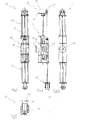
- FIG. 1 to 3 shows a grinding machine 10 for internal machining of molds with a mold 11 in different Views.
- the grinding machine is essentially formed from a positioning device 12 and a grinding device 13, wherein the positioning device has an arm 14, at the end 15 of the grinding device 13 is arranged.
- the grinding device 13 can be positioned relative to a radially inner surface 17 of the mold 11.
- the grinding device 13 is supported by means of a rotating device 18 of the positioning device 12 on the arm 14 indefinitely rotatable about a rotation axis 19 of the rotating device 18.
- the longitudinal axis 20 is arranged substantially horizontally, characterized in that the mold 11 was placed and aligned on a support 21. Due to the high weight of the mold 11 of several tons, a further attachment of the mold 11 on the support 21 is not required.
- the grinding machine 10 is aligned by means of stops 22 with respect to the mold 11. The stops 22 arrive at an end face 23 of the mold 11 to the plant.
- the radial inner surface 17 of the mold 11 further has a conical contour 24.
- the arm 14 is movable by means of a gear drive 25 in the direction of the longitudinal axis 20 so that the grinding device 13 can be positioned along the radial inner surface 17.
- turning device 18 is formed so that on a flange 26, the grinding device 13 can be detachably mounted. This also makes it possible, if necessary, to exchange the grinding device 13 for a smaller or larger grinding device, not shown here, if, for example, molds with substantially smaller or larger inner diameters are to be processed.
- the rotating device 18 is attached via a flange 27 to the arm 14 and connected via a coupling 28 with a rotary drive, not shown here.
- a synopsis of Fig. 5 to 8 shows the grinding device 13 in different views.
- the grinding device 13 has a motor-driven grinding device 29, which in turn is formed by a hydraulic rotary motor 30 and a grinding wheel 31. Further, the grinding device 13 on a support means 32 which is formed from a pair of wheels 33.
- the grinding wheel 31 and the wheel pair 33 are arranged so that they are aligned relative to each other and at right angles relative to a rotational axis 34 of the grinding device 13 and the longitudinal axis 20 of the mold 11.
- the grinding device 13 further has a pressure device 35 on which the grinding device 29 and the support device 32 are arranged.
- the pressure device 35 is formed from pneumatic cylinders 36 and 37 with rod guides 38 and 39, respectively.
- a flange 40 for connection to the flange 26 of the rotator 18 is provided.
- the pneumatic cylinders 36 and 37 By means of the pneumatic cylinders 36 and 37, the grinding device 29 and the support means 32 can be moved independently of one another transversely to the longitudinal axis 20.
- a control device not shown here a constant contact pressure on the radial inner surface 17 of the mold 11 can be effected via the pneumatic cylinder 36 and 37.
Landscapes
- Engineering & Computer Science (AREA)
- Mechanical Engineering (AREA)
- Grinding And Polishing Of Tertiary Curved Surfaces And Surfaces With Complex Shapes (AREA)
- Grinding Of Cylindrical And Plane Surfaces (AREA)
Description
- Die Erfindung betrifft eine Schleifmaschine und ein Verfahren zur Innenbearbeitung von Kokillen, wie z.B. bekannt aus dem Dokument
DE 84 06 650 U1 , wobei die Schleifmaschine eine Positioniervorrichtung und eine Schleifvorrichtung umfasst, wobei die Schleifvorrichtung an einem Ende eines Arms der Positioniervorrichtung angeordnet ist und mittels der Positioniervorrichtung relativ zu einer radialen Innenfläche einer Kokille positionierbar ist, wobei die Schleifvorrichtung eine motorgetriebene Schleifeinrichtung zur Bearbeitung der radialen Innenfläche der Kokille aufweist. - Kokillen für den Stahlguss weisen eine geometrisch einfache Form, beispielsweise eine runde oder rechteckige Ringform, auf und bestehen üblicherweise aus Sphäroguss. Bei einer mehrfachen Verwendung einer derartigen Kokille zum Blockguss von Stahl bilden sich auf einer radialen Innenfläche der Kokille unerwünschte Verunreinigungen, die in Folge eine Qualität einer Oberfläche eines Stahlblocks vermindern. Insbesondere auch durch einen hohen Temperaturunterschied zwischen der radialen Innenfläche der Kokille und einer Außenfläche beim bzw. nach dem Eingießen flüssigen Stahls kommt es in den Eckbereichen der Kokille zu Spannungsrissen, die ebenfalls eine Oberflächenqualität eines Blocks negativ beeinflussen. Daher ist es bekannt, zur Vermeidung einer aufwändigen Nachbearbeitung eines gegossenen Blocks eine radiale Innenfläche einer Kokille in regelmäßigen Abständen zu schleifen, um eventuell vorhandene Schadstellen zu beseitigen. Dazu werden speziell für diesen Zweck ausgebildete Schleifmaschinen verwandt.
- Diese Schleifmaschinen sind regelmäßig so ausgebildet, dass eine Schleifvorrichtung mit einem rotierenden Schleifmittel mittels einer Positioniervorrichtung innerhalb der Kokille an deren radialen Innenfläche entlang bewegt wird. Da die radiale Innenfläche der Kokille jedoch in Richtung einer Längsachse der Kokille leicht konisch ausgebildet ist und bei einer quadratischen oder rechteckigen Kokillenform einen Eckenradius bzw. gerundete Ecken aufweist, ist ein maßhaltiges Schleifen der radialen Innenfläche der Kokille nicht ohne weiteres möglich. Um einen gleichmäßigen Materialabtrag von der radialen Innenfläche zu erzielen, ist es daher erforderlich, die Kokille vor einer Schleifbearbeitung zu vermessen. Die radiale Innenfläche kann dann mittels einer CNC-gesteuerten Schleifmaschine entsprechend einer genauen Maßvorgabe auf ein Sollmaß geschliffen werden. Ein genaues Vermessen einer Kokille und die entsprechende Programmierung einer CNC-gesteuerten Schleifmaschine ist jedoch relativ zeitaufwändig und damit teuer.
- Auch ist es bekannt, Kokillen mit halbautomatischen Schleifmaschinen zu schleifen. Hier ist jedoch nachteilig, dass je nach der Größe der Kokille von beispielsweise bis zu 4 m Innendurchmesser die radiale Innenfläche der Kokille nicht allseitig von der Schleifmaschine erreicht werden kann, insbesondere, wenn sie von einer Person bedient wird. So kann beispielsweise nur eine horizontal angeordnete radiale Innenfläche der Kokille geschliffen werden, und es ist erforderlich, die Kokille zur Bearbeitung der übrigen Flächenabschnitte mittels eines Krans mehrfach zu drehen. Auch diese Art des Schleifens ist bei großformatigen Kokillen für den Blockguss, insbesondere aufgrund des hohen Gewichts von mehreren Tonnen der Kokille und der damit verbundenen schwierigen Handhabung, relativ zweitaufwändig. Im Übrigen kann keine besonders genaue Maßhaltigkeit der geschliffenen radialen Innenfläche der Kokille erzielt werden.
- Bei den aus dem Stand der Technik bekannten, sogenannten Langarmschleifmaschinen für Großkillen kann auch nur eine mäßige Anpresskraft für das Schleifmittel erzielt werden, was relativ lange Schleif- oder Bürstenzeiten zur Bearbeitung der Kokille zur Folge hat. Weitere Kosten entstehen dadurch, dass Krananlagen zum Drehen der Kokille bzw. aufwändige Dreh- oder Rolltische ständig zur Bearbeitung der Kokille verfügbar sein müssen.
- Der vorliegenden Erfindung liegt daher die Aufgabe zugrunde, eine Schleifmaschine sowie ein Verfahren zur Innenbearbeitung von Kokillen vorzuschlagen, die bzw. das eine vereinfachte Bearbeitung und damit ein schnelleres und kostengünstigeres Schleifen einer radialen Innenfläche einer Kokille ermöglicht.
- Diese Aufgabe wird durch eine Schleifmaschine mit den Merkmalen des Anspruchs 1 und ein Verfahren mit den Merkmalen des Anspruchs 14 gelöst.
- Die erfindungsgemäße Schleifmaschine zur Innenbearbeitung von Kokillen umfasst eine Positioniervorrichtung und eine Schleifvorrichtung, wobei die Schleifvorrichtung an einem Ende eines Arms der Positioniervorrichtung angeordnet ist und mittels der Positioniervorrichtung relativ zu einer radialen Innenfläche einer Kokille positionierbar ist, wobei die Schleifvorrichtung eine motorgetriebene Schleifeinrichtung zur Bearbeitung der radialen Innenfläche der Kokille aufweist, wobei die Schleifvorrichtung eine Stützeinrichtung aufweist, die relativ zu einer Längsachse der Kokille an der radialen Innenfläche gegenüber der Schleifeinrichtung anordbar ist, wobei die Schleifvorrichtung eine Andruckeinrichtung aufweist, die die Schleifeinrichtung und die Stützeinrichtung gegeneinander abstützen und gegen die radiale Innenfläche pressen kann.
- Insbesondere durch die erfindungsgemäße Ausbildung der Schleifvorrichtung wird es möglich, Kokillen bis zu einem Innendurchmesser von bis zu 4 m oder größer zu schleifen, ohne dass die betreffende Kokille mittels eines Krans oder Ähnlichem bewegt werden müsste. Da die motorgetriebene Schleifeinrichtung mittels der Positioniervorrichtung bzw. deren Arm an im Wesentlichen jede Stelle der radialen Innenfläche der Kokille bewegt werden kann, kann die Kokille in einem Arbeitsgang ohne Unterbrechungen geschliffen werden. Ein genaues Vermessen der Kokille vor einem Schleifen ist nicht mehr notwendig, da eine besonders genaue Maßhaltigkeit durch die Ausbildung der Schleifvorrichtung erzielt werden kann. So kann auf einen Einsatz einer CNC-Steuerung vollständig verzichtet werden, so dass die Schleifmaschine selbst kostengünstiger herstellbar wird. Die Schleifvorrichtung erstreckt sich im Wesentlichen quer zu der Längsachse der Kokille und weist an einem an der Innenfläche anliegenden Ende die motorgetriebene Schleifeinrichtung und an einem gegenüberliegenden, ebenfalls an der Innenfläche anliegenden Ende die Stützeinrichtung auf. Zwischenliegend ist die Andruckeinrichtung angeordnet, die die Stützeinrichtung und die motorgetriebene Schleifeinrichtung mit einer gleichmäßigen Kraft an die radiale Innenfläche pressen kann. Mittels der Andruckeinrichtung ist ein Relativabstand von motorgetriebener Schleifeinrichtung und Stützeinrichtung innerhalb eines großen Bereichs variabel, so dass die Schleifvorrichtung für Großkokillen unterschiedlicher Innendurchmesser verwendet werden und sich auch immer an eine jeweilige Kontur der radialen Innenfläche der Kokille mittels der Andruckeinrichtung anpassen kann.
- Im Unterschied zu einer aus dem Stand der Technik bekannten, alleine an einem Arm gehalterten Schleifeinrichtung wird bei der Erfindung die zum Schleifen erforderliche Anpresskraft nicht durch den Arm aufgebracht, sondern durch die Andruckeinrichtung mit der Stützeinrichtung als Widerlager auf der gegenüberliegenden Seite der motorgetriebenen Schleifeinrichtung. Da keine genaue Vermessung der Kokille und Programmierung einer CNC-Steuerung erforderlich ist, verkürzen sich bei der erfindungsgemäßen Schleifmaschine die Rüstzeiten erheblich. Weiter kann auch aufgrund der gegenüberliegenden Abstützung ein vergleichsweise hoher Anpressdruck für ein Schleifmittel erzielt werden, wodurch sich auch eine Bearbeitungszeit wesentlich verkürzt. Insgesamt können so Kosten für die eingesetzte Schleifmaschine und die Bearbeitung der Kokille eingespart werden.
- In einer Ausführungsform kann die Positioniervorrichtung eine Dreheinrichtung aufweisen, mittels der die Schleifvorrichtung relativ zu der Längsachse drehbar ist. Die motorgetriebene Schleifeinrichtung kann dann so um die Längsachse der Kokille gedreht werden, dass mit einem Schleifmittel jeder Punkt der radialen Innenfläche der Kokille erreicht werden kann. Die Dreheinrichtung kann an dem Ende des Arms der Positioniervorrichtung ausgebildet sein oder kann sich auch innerhalb des Arms befinden. Weiter ist es denkbar, dass der Arm selbst drehbar ausgebildet ist.
- Vorteilhaft kann die Dreheinrichtung dann eine Drehung der Schleifeinrichtung von über 360 ° ermöglichen.
- Weiter kann die Dreheinrichtung eine Drehdurchführung zur Kopplung von Versorgungsleitungen der Schleifvorrichtung aufweisen, wobei die Drehdurchführung dann eine unbegrenzte Drehung der Schleifvorrichtung ermöglicht. Durch eine unbegrenzte Drehung der Schleifvorrichtung bzw. motorgetriebenen Schleifeinrichtung ist gegenüber einer begrenzten Drehung der Schleifvorrichtung ein Zurückdrehen nicht mehr erforderlich, so dass Verfahrwege der motorgetriebenen Schleifeinrichtung verkürzt und eine kontinuierliche und damit schnellere Bearbeitung der radialen Innenfläche der Kokille ermöglicht werden kann. Vorhandene Versorgungsleitungen, wie beispielsweise Pneumatik-, Hydraulik- oder Stromversorgungs- und Steuerungsleitungen können beiderseits der Drehdurchführung angeschlossen sein. Die Drehdurchführung selbst kann zur Durchleitung von Medien kreisförmige Kanäle und zur Weiterleitung elektrischer Energie beispielsweise Schleifringe aufweisen.
- Die Positioniervorrichtung kann eine Zentriereinrichtung aufweisen, mittels der eine Drehachse der Schleifvorrichtung bzw. Schleifeinrichtung mit der Längsachse der Kokille in Übereinstimmung gebracht werden kann. Die Schleifeinrichtung kann dann um die Längsachse der Kokille rotiert bzw. in Längsrichtung der Längsachse auch bewegt werden. Dadurch wird ein besonders genaues maßhaltigen Arbeiten mit der Schleifmaschine bzw. ein gleichmäßiger Abtrag von Material der Innenfläche der Kokille ermöglicht. Die Zentriereinrichtung kann im Wesentlichen so ausgebildet sein, dass der Arm der Positioniervorrichtung relativ zu einer Maschinenbasis der Schleifmaschine, die gegenüber der Kokille unbewegt ist, bewegt werden kann. So kann der Arm dann mittels der Zentriereinrichtung quer zur Längsachse der Kokille horizontal und vertikal positioniert werden.
- Dazu kann die Zentriereinrichtung einen in einer Höhe verstellbaren Scherentisch aufweisen. Da der Arm bzw. die Antriebseinrichtung der Schleifmaschine ein vergleichsweise hohes Gewicht aufweisen, können diese Einrichtungen mittels des Scherentischs auf eine besonders einfache Weise vollständig angehoben und abgesenkt werden. Da ein Scherentisch besonders einfach ausbildbar ist und dennoch eine genaue Höhenverstellung des Arms ermöglicht, können auch hier weitere Kosten für die Herstellung der Schleifmaschine eingespart werden.
- Weiter kann der Arm der Positioniervorrichtung in Richtung der Längsachse der Kokille mittels eines Linearantriebs bewegbar sein. Der Linearantrieb kann beispielsweise ein Linearmotor, ein Antrieb mit einer Gewindespindel oder auch ein Zahnstangenantrieb sein. Insbesondere ein Zahnstangenantrieb ist besonders einfach realisierbar und gut an die Einsatzbedingungen beim Kokillenschleifen anpassbar.
- Auch ist es von Vorteil, wenn die Schleifmaschine eine Steuerungsvorrichtung aufweist, mittels der eine Anpresskraft der Andruckeinrichtung gesteuert werden kann. So kann die Steuerungsvorrichtung beispielsweise eine Messeinrichtung umfassen, die eine von der Andruckeinrichtung erzeugte Anpresskraft des verwendeten Schleifmittels auf die radiale Innenfläche der Kokille misst. Die Steuerungsvorrichtung kann dann die Andruckeinrichtung so steuern bzw. eine Anpresskraft regeln, so dass die Anpresskraft im Wesentlichen unabhängig von einer Kontur der radialen Innenfläche der Kokille konstant ist. Weiter kann die Steuerungsvorrichtung dazu dienen, die Schleifvorrichtung mittels der Positioniervorrichtung zu bewegen. Zwar kann auf einen Einsatz einer CNC-Steuerung verzichtet werden, jedoch schließt dies eine Verwendung einer CNC-Steuerung im Rahmen der Steuerungsvorrichtung nicht aus.
- Die Andruckeinrichtung kann zwei Linearantriebe aufweisen, mittels derer jeweils die Schleifeinrichtung und die Stützeinrichtung quer zur Längsachse der Kokille bewegt werden können. Demnach kann für die Schleifeinrichtung ein Linearantrieb und für die Stützeinrichtung ein weiterer Linearantrieb vorgesehen sein. Die Linearantriebe können jeweils an das Ende des Arms der Positioniervorrichtung gekoppelt sein, und dann die Stützeinrichtung und die Schleifeinrichtung ausgehend von dem Arm in radialer Richtung relativ zur Längsachse der Kokille unabhängig voneinander bewegen. Eventuelle Mittelnabweichungen des Arms relativ zur Längsachse der Kokille können so auch kompensiert werden. Weiter kann vorgesehen sein, die Linearantriebe so miteinander zu koppeln, dass von den Linearantrieben die gleiche Anpresskraft auf die radiale Innenfläche der Kokille bewirkt wird.
- Vorzugsweise können die Linearantriebe Pneumatikzylinder sein. Pneumatikzylinder sind im Vergleich zu motorgetriebenen Linearantrieben relativ kostengünstig und können einen ausreichenden Anpressdruck erzielen. Weiter kann mittels der Pneumatikzylinder ein vergleichsweise langer Verfahrweg für die Stützeinrichtung und die Schleifeinrichtung erzielt werden, so dass Kokillen mit unterschiedlichsten Innendurchmessern mit der gleichen Schleifmaschine bearbeitet werden können. Da bei einer Bewegung bzw. Positionierung der Schleifeinrichtung und der Stützeinrichtung kein Anfahren eines Punktes eines Koordinatensystems, wie bei einer CNC-Steuerung, erforderlich ist, können die Pneumatikzylinder auch ohne die Verwendung eines Längenmesssystems eingesetzt werden.
- Die Schleifeinrichtung kann einen Motor bzw. Rotationsmotor aufweisen, der ein Schleifmittel antreiben kann. Der Motor kann ein Elektromotor oder vorzugsweise ein hydraulisch angetriebener Motor sein. Das Schleifmittel kann eine scheibenförmige Schleifscheibe, eine topfförmige Schleifscheibe, eine Bürste oder auch ein Schleifband sein. Eine scheibenförmige Schleifscheibe kann vorzugsweise in radialer Richtung relativ zur Längsachse der Kokille angeordnet sein, so dass die Schleifscheibe durch eine schraubenförmige Bewegung die Kontur der radialen Innenfläche der Kokille abfahren und bearbeiten kann. Weiter kann die Schleifeinrichtung so ausgebildet sein, dass die Schleifscheibe dann relativ zur Längsachse der Kokille um einen Winkel α geschwenkt werden kann, um die Schleifscheibe an einen Konus der Innenfläche der Kokille mit einem übereinstimmenden Winkel α anpassen zu können.
- Eine noch effektivere Bearbeitung der Innenfläche der Kokille wird möglich, wenn die Stützeinrichtung als eine weitere Schleifeinrichtung zur Bearbeitung der radialen Innenfläche der Kokille ausgebildet ist. Folglich kann dann die Schleifvorrichtung jeweils zwei Schleifeinrichtungen aufweisen, die gegenüberliegend angeordnet sind und sich gegeneinander an der radialen Innenfläche der Kokille abstützen können. Auch ist es denkbar, dass die Schleifvorrichtung mehrere Paare von sich gegenüberliegenden Schleifeinrichtungen aufweist.
- Die Stützeinrichtung kann auch als zumindest ein Rad ausgebildet sein, welches sich an der radialen Innenfläche der Kokille abwälzen kann. So kann eine besonders einfache Abstützung der Schleifeinrichtung sichergestellt werden, ohne dass eine Drehung der Schleifvorrichtung durch eine Reibung der Stützeinrichtung an der radialen Innenfläche behindert wird.
- Bei dem erfindungsgemäßen Verfahren zur Innenbearbeitung von Kokillen mit einer Schleifmaschine, die eine Positioniervorrichtung und eine Schleifvorrichtung umfasst, ist die Schleifvorrichtung an einem Ende eines Arms der Positioniervorrichtung angeordnet und wird mittels der Positioniervorrichtung relativ zu einer radialen Innenfläche einer Kokille positioniert, wobei die Schleifvorrichtung eine motorgetriebene Schleifeinrichtung zum Schleifen der radialen Innenfläche und eine Stützeinrichtung aufweist, die relativ zu einer Längsachse der Kokille gegenüberliegend an der radialen Innenfläche angeordnet werden, wobei die Schleifeinrichtung und die Stützeinrichtung mittels einer Andruckeinrichtung der Schleifvorrichtung gegeneinander abgestützt und gegen die radiale Innenfläche gepresst werden. Zu den Vorteilen des erfindungsgemäßen Verfahrens wird auf die Vorteilsbeschreibung der erfindungsgemäßen Schleifmaschine verwiesen.
- In einer Ausführungsform des Verfahrens kann dann mittels der Andruckvorrichtung eine konstante Anpresskraft auf die radiale Innenfläche der Kokille bewirkt werden. Dadurch, dass die radiale Innenfläche der Kokille durchgängig mit einer konstanten Anpresskraft geschliffen werden kann, ist eine Positionierung der Schleifeinrichtung mit Bezug zu einem Koordinatensystem, wie bei einer CNC-Steuerung, nicht notwendig, da aufgrund der konstanten Anpresskraft ein gleichmäßiger und damit weitestgehend maßhaltiger Abtrag von Material der radialen Innenfläche erzielt werden kann.
- Weiter kann die Schleifeinrichtung relativ zu der Längsachse der Kokille radial und axial bewegt werden, wobei die Schleifeinrichtung an eine Kontur der radialen Innenfläche der Kokille mittels der Andruckeinrichtung angepasst werden kann, wobei die Anpassung in Abhängigkeit einer auf die Schleifeinrichtung mittels der Andruckeinrichtung bewirkten Anpresskraft erfolgen kann. So kann die Anpresskraft mittels einer Messeinrichtung gemessen werden, beispielsweise mittels einer Druckmessung bei einer Verwendung von Pneumatikkolben für die Andruckeinrichtung, wobei dann bei einem aufgrund einer sich verändernden Kontur der radialen Innenfläche veränderten Druck dieser wieder angepasst bzw. auf einen Sollwert geregelt werden kann.
- Weitere vorteilhafte Ausführungsformen des Verfahrens ergeben sich aus den Merkmalsbeschreibungen der auf den Vorrichtungsanspruch 1 zurückbezogenen Unteransprüche.
- Nachfolgend wird eine bevorzugte Ausführungsform der Erfindung unter Bezugnahme auf die beigefügten Zeichnungen näher erläutert.
- Es zeigen:
- Fig. 1
- Eine Vorderansicht einer Ausführungsform einer Schleifmaschine zur Innenbearbeitung von Kokillen mit einer Kokille;
- Fig. 2
- eine Draufsicht der Schleifmaschine aus
Fig. 1 ; - Fig. 3
- eine Seitenansicht von links der Schleifmaschine aus
Fig. 1 ; - Fig. 4
- eine Seitenansicht einer Dreheinrichtung;
- Fig. 5
- eine Seitenansicht von rechts einer Schleifvorrichtung;
- Fig. 6
- eine Vorderansicht der Schleifvorrichtung;
- Fig. 7
- eine Seitenansicht von links der Schleifeinrichtung;
- Fig. 8
- eine Draufsicht der Schleifvorrichtung.
- Eine Zusammenschau der
Fig. 1 bis 3 zeigt eine Schleifmaschine 10 zur Innenbearbeitung von Kokillen mit einer Kokille 11 in verschiedenen Ansichten. Die Schleifmaschine ist im Wesentlichen aus einer Positioniervorrichtung 12 und einer Schleifvorrichtung 13 gebildet, wobei die Positioniervorrichtung einen Arm 14 aufweist, an dessen Ende 15 die Schleifvorrichtung 13 angeordnet ist. Mittels des relativ zu einer Maschinenbasis 16 der Schleifmaschine 10 bewegbaren Arms 14 kann die Schleifvorrichtung 13 relativ zu einer radialen Innenfläche 17 der Kokille 11 positioniert werden. Die Schleifvorrichtung 13 ist mittels einer Dreheinrichtung 18 der Positioniervorrichtung 12 an dem Arm 14 unbegrenzt drehbar um eine Drehachse 19 der Dreheinrichtung 18 gelagert. Bei der Positionierung der Schleifvorrichtung 13 wird diese so ausgerichtet, dass die Drehachse 19 mit einer Längsachse 20 der Kokille 11 im Wesentlichen fluchtet. Die Längsachse 20 ist im Wesentlichen horizontal angeordnet, dadurch, dass die Kokille 11 auf einem Auflager 21 aufgesetzt und ausgerichtet wurde. Aufgrund des hohen Eigengewichts der Kokille 11 von mehreren Tonnen ist eine weitergehende Befestigung der Kokille 11 auf dem Auflager 21 nicht erforderlich. Die Schleifmaschine 10 ist mittels Anschlägen 22 gegenüber der Kokille 11 ausgerichtet. Die Anschläge 22 gelangen an einer Stirnfläche 23 der Kokille 11 zur Anlage. Die radiale Innenfläche 17 der Kokille 11 weist weiter eine konische Kontur 24 auf. Der Arm 14 ist mittels eines Zahnradantriebs 25 in Richtung der Längsachse 20 so bewegbar, dass die Schleifvorrichtung 13 entlang der radialen Innenfläche 17 positioniert werden kann. - Die in
Fig. 4 dargestellte Dreheinrichtung 18 ist so ausgebildet, dass an einem Flansch 26 die Schleifvorrichtung 13 lösbar montiert werden kann. Dadurch wird es auch möglich, die Schleifvorrichtung 13 gegebenenfalls gegen eine hier nicht dargestellte kleinere oder größere Schleifvorrichtung auszutauschen, wenn beispielsweise Kokillen mit wesentlich kleineren oder größeren Innendurchmessern bearbeitet werden sollen. Die Dreheinrichtung 18 ist über einen Flansch 27 an dem Arm 14 befestigt und über eine Kupplung 28 mit einem hier nicht näher dargestellten Drehantrieb verbunden. Mittels einer hier nicht näher beschriebenen Drehdurchführung der Dreheinrichtung 18 wird eine Kopplung von hier ebenfalls nicht dargestellten Versorgungsleitungen der Schleifvorrichtung 13 mit dem Arm 14 bei einer unbegrenzten Drehung der Schleifvorrichtung 13 möglich. - Eine Zusammenschau der
Fig. 5 bis 8 zeigt die Schleifvorrichtung 13 in verschiedenen Ansichten. Die Schleifvorrichtung 13 weist eine motorbetriebene Schleifeinrichtung 29 auf, die ihrerseits aus einem hydraulischen Rotationsmotor 30 und einer Schleifscheibe 31 gebildet ist. Weiter weist die Schleifvorrichtung 13 eine Stützeinrichtung 32 auf, die aus einem Radpaar 33 gebildet ist. Die Schleifscheibe 31 und das Radpaar 33 sind so angeordnet, dass diese relativ zueinander gegenüberliegend und rechtwinklig bezogen auf eine Drehachse 34 der Schleifvorrichtung 13 bzw. der Längsachse 20 der Kokille 11 fluchten. - Die Schleifvorrichtung 13 weist weiter eine Andruckeinrichtung 35 auf, an der die Schleifeinrichtung 29 und die Stützeinrichtung 32 angeordnet sind. Die Andruckeinrichtung 35 ist aus Pneumatikzylindern 36 und 37 mit Stabführungen 38 bzw. 39 gebildet. Weiter ist ein Flansch 40 zur Verbindung mit dem Flansch 26 der Dreheinrichtung 18 vorgesehen. Mittels der Pneumatikzylinder 36 bzw. 37 können die Schleifeinrichtung 29 und die Stützeinrichtung 32 unabhängig voneinander quer zur Längsachse 20 bewegt werden. Mittels einer hier nicht näher dargestellten Steuerungsvorrichtung kann über die Pneumatikzylinder 36 und 37 eine konstante Anpresskraft auf die radiale Innenfläche 17 der Kokille 11 bewirkt werden. Da die Schleifscheibe 31 mittels des Radpaars 33 an der gegenüberliegenden radialen Innenfläche 17 abgestützt ist, kann eine vergleichsweise große Anpresskraft erzielt werden. Da mittels der Steuerungsvorrichtung die Anpresskraft unabhängig von der konischen Kontur 24 konstant gehalten werden kann, ist eine besondere maßliche Erfassung des Innendurchmessers der Kokille 11 mittels der Schleifmaschine 10 nicht erforderlich. Zum Schleifen der radialen Innenfläche 17 ist es lediglich ausreichend, die Schleifeinrichtung 29 in Richtung der Längsachse 20 zu bewegen und dabei die Schleifeinrichtung 29 um die Längsachse 20 zu rotieren, wobei mittels der Schleifscheibe 31 dann ein Schleifen der radialen Innenfläche 17 erfolgt. Selbst ein Verschleiß der Schleifscheibe 31, welcher eine Verkleinerung eines Durchmessers der Schleifscheibe 31 zur Folge hat, muss hier nicht durch eine besondere maßliche Einstellung der Schleifmaschine 10 korrigiert werden, da über den konstanten Anpressdruck der Schleifscheibe 31 eine Kompensation einer Durchmesseränderung bei einem gleichmäßigen Materialabtrag von der radialen Innenfläche 17 erfolgt.
Claims (16)
- Schleifmaschine (10) zur Innenbearbeitung von Kokillen, wobei die Schleifmaschine eine Positioniervorrichtung (12) und eine Schleifvorrichtung (13) umfasst, wobei die Schleifvorrichtung an einem Ende (15) eines Arms (14) der Positioniervorrichtung angeordnet ist und mittels der Positioniervorrichtung relativ zu einer radialen Innenfläche (17) einer Kokille (11) positionierbar ist, wobei die Schleifvorrichtung eine motorgetriebene Schleifeinrichtung (29) zur Bearbeitung der radialen Innenfläche der Kokille aufweist,
dadurch gekennzeichnet,
dass die Schleifvorrichtung eine Stützeinrichtung (32) aufweist, die relativ zu einer Längsachse (20) der Kokille an der radialen Innenfläche gegenüberliegend der Schleifeinrichtung anordbar ist, wobei die Schleifvorrichtung eine Andruckeinrichtung (35) aufweist, die die Schleifeinrichtung und die Stützeinrichtung gegeneinander abstützen und gegen die radiale Innenfläche pressen kann. - Schleifmaschine nach Anspruch 1,
dadurch gekennzeichnet,
dass die Positioniervorrichtung (12) eine Dreheinrichtung (18) aufweist, mittels der die Schleifvorrichtung (13) relativ zu der Längsachse (20) drehbar ist. - Schleifmaschine nach Anspruch 2,
dadurch gekennzeichnet,
dass die Dreheinrichtung (18) eine Drehung der Schleifvorrichtung (13) von über 360° ermöglicht. - Schleifmaschine nach Anspruch 2 oder 3,
dadurch gekennzeichnet,
dass die Dreheinrichtung (18) eine Drehdurchführung zur Kopplung von Versorgungsleitungen der Schleifvorrichtung (13) aufweist, wobei die Drehdurchführung eine unbegrenzte Drehung der Schleifvorrichtung ermöglicht. - Schleifmaschine nach einem der vorangehenden Ansprüche,
dadurch gekennzeichnet,
dass die Positioniervorrichtung (12) eine Zentriereinrichtung aufweist, mittels der eine Drehachse (34) der Schleifvorrichtung (13) mit der Längsachse (20) der Kokille (11) in Übereinstimmung gebracht werden kann. - Schleifmaschine nach Anspruch 5,
dadurch gekennzeichnet,
dass die Zentriereinrichtung einen in einer Höhe verstellbaren Scherentisch aufweist. - Schleifmaschine nach einem der vorangehenden Ansprüche,
dadurch gekennzeichnet,
dass der Arm (14) der Positioniervorrichtung (12) in Richtung der Längsachse (20) der Kokille (11) mittels eines Linearantriebes bewegbar ist. - Schleifmaschine nach einem der vorangehenden Ansprüche,
dadurch gekennzeichnet,
dass die Schleifmaschine (10) eine Steuerungsvorrichtung aufweist, mittels der eine Anpresskraft der Andruckeinrichtung (35) gesteuert werden kann. - Schleifmaschine nach einem der vorangehenden Ansprüche,
dadurch gekennzeichnet,
dass die Andruckeinrichtung (35) zwei Linearantriebe aufweist, mittels derer jeweils die Schleifeinrichtung (29) und die Stützeinrichtung (32) quer zur Längsachse (20) der Kokille (11) bewegt werden können. - Schleifmaschine nach Anspruch 9,
dadurch gekennzeichnet,
dass die Linearantriebe Pneumatikzylinder (36, 37) sind. - Schleifmaschine nach einem der vorangehenden Ansprüche,
dadurch gekennzeichnet,
dass die Schleifeinrichtung (29) einen Motor (30) aufweist, der ein Schleifmittel (31) antreiben kann. - Schleifmaschine nach einem der vorangehenden Ansprüche,
dadurch gekennzeichnet,
dass die Stützeinrichtung (32) als eine weitere Schleifeinrichtung zur Bearbeitung der radialen Innenfläche (17) der Kokille (11) ausgebildet ist. - Schleifmaschine nach einem der Ansprüche 1 bis 11,
dadurch gekennzeichnet,
dass die Stützeinrichtung (32) als zumindest ein Rad (33) ausgebildet ist, welches sich an der radialen Innenfläche (17) der Kokille (11) abwälzen kann. - Verfahren zur Innenbearbeitung von Kokillen, mit einer Schleifmaschine (10) die eine Positioniervorrichtung (12) und eine Schleifvorrichtung (13) umfasst, wobei die Schleifvorrichtung an einem Ende (15) eines Arms (14) der Positioniervorrichtung angeordnet ist und mittels der Positioniervorrichtung relativ zu einer radialen Innenfläche (17) einer Kokille (11) positioniert wird,
dadurch gekennzeichnet,
dass die Schleifvorrichtung eine motorgetriebene Schleifeinrichtung (29) zum Schleifen der radialen Innenfläche und eine Stützeinrichtung (32) aufweist, die relativ zu einer Längsachse (20) der Kokille gegenüberliegend an der radialen Innenfläche angeordnet werden, wobei die Schleifeinrichtung und die Stützeinrichtung mittels einer Andruckeinrichtung (35) der Schleifvorrichtung gegeneinander abgestützt und gegen die radiale Innenfläche gepresst werden. - Verfahren nach Anspruch 14,
dadurch gekennzeichnet,
dass mittels der Andruckeinrichtung (35) eine konstante Anpresskraft auf die radiale Innenfläche (17) der Kokille (11) bewirkt wird. - Verfahren nach Anspruch 14 oder 15,
dadurch gekennzeichnet,
dass die Schleifeinrichtung (29) relativ zu der Längsachse (20) der Kokille (11) radial und axial bewegt wird, wobei die Schleifeinrichtung an eine Kontur (24) der radialen Innenfläche (17) der Kokille mittels der Andruckeinrichtung (35) angepasst wird, wobei die Anpassung in Abhängigkeit einer auf die Schleifeinrichtung mittels der Andruckeinrichtung bewirkten Anpresskraft erfolgt.
Priority Applications (2)
| Application Number | Priority Date | Filing Date | Title |
|---|---|---|---|
| PL12182794T PL2578358T3 (pl) | 2011-10-07 | 2012-09-03 | Szlifierka oraz sposób obróbki wewnętrznej kokili |
| SI201230037T SI2578358T1 (sl) | 2011-10-07 | 2012-09-03 | Brusilni stroj in postopek za notranjo obdelavo kokil |
Applications Claiming Priority (1)
| Application Number | Priority Date | Filing Date | Title |
|---|---|---|---|
| DE202011106414 | 2011-10-07 |
Publications (3)
| Publication Number | Publication Date |
|---|---|
| EP2578358A2 EP2578358A2 (de) | 2013-04-10 |
| EP2578358A3 EP2578358A3 (de) | 2013-08-07 |
| EP2578358B1 true EP2578358B1 (de) | 2014-03-19 |
Family
ID=46796436
Family Applications (1)
| Application Number | Title | Priority Date | Filing Date |
|---|---|---|---|
| EP12182794.3A Active EP2578358B1 (de) | 2011-10-07 | 2012-09-03 | Schleifmaschine und Verfahren zur Innenbearbeitung von Kokillen |
Country Status (3)
| Country | Link |
|---|---|
| EP (1) | EP2578358B1 (de) |
| PL (1) | PL2578358T3 (de) |
| SI (1) | SI2578358T1 (de) |
Families Citing this family (1)
| Publication number | Priority date | Publication date | Assignee | Title |
|---|---|---|---|---|
| CN104070439B (zh) * | 2014-06-27 | 2016-05-18 | 北京京诚之星科技开发有限公司 | 模锻锻件表面缺陷清理机组 |
Family Cites Families (3)
| Publication number | Priority date | Publication date | Assignee | Title |
|---|---|---|---|---|
| DE2048407C3 (de) * | 1970-10-02 | 1979-09-06 | Evertz, Egon, 5650 Solingen | Schleifmaschine zum Bearbeiten von bezüglich ihrer Mantellinien geraden Innenflächen von Hohlkörpern |
| DE8406650U1 (de) * | 1984-03-03 | 1984-07-26 | Schweißtechnik Düsseldorf GmbH & Co KG, 4000 Düsseldorf | Schleifvorrichtung zum innenschleifen der waende von block- und brammenkokillen |
| ATE283741T1 (de) * | 2000-04-11 | 2004-12-15 | Concast Standard Ag | Vorrichtung und verfahren zum bearbeiten von hohlraumwänden einer stranggiesskokille |
-
2012
- 2012-09-03 PL PL12182794T patent/PL2578358T3/pl unknown
- 2012-09-03 SI SI201230037T patent/SI2578358T1/sl unknown
- 2012-09-03 EP EP12182794.3A patent/EP2578358B1/de active Active
Also Published As
| Publication number | Publication date |
|---|---|
| EP2578358A2 (de) | 2013-04-10 |
| EP2578358A3 (de) | 2013-08-07 |
| PL2578358T3 (pl) | 2014-08-29 |
| SI2578358T1 (sl) | 2014-07-31 |
Similar Documents
| Publication | Publication Date | Title |
|---|---|---|
| DE102013001675B4 (de) | Vorrichtung zur Montage und Demontage von Hydraulikzylindern | |
| DE102014204807B4 (de) | Verfahren und Vorrichtung zum Schleifen von Großkurbelwellen | |
| DE10234707A1 (de) | Verfahren und Vorrichtung zum Schleifen eines rotationssymmetrischen Maschinenbauteils | |
| DE102014003598A1 (de) | Vorrichtung zum Schleifen, Feinschleifen und/oder Polieren von Werkstücken in optischer Qualität, insbesondere von sphärischen Linsenflächen in der Feinoptik | |
| EP3678799B1 (de) | Radial-axial-ringwalzwerk zum walzen eines ringes | |
| EP0325799B1 (de) | Fliehkraftbearbeitungsmaschine | |
| EP2275217A1 (de) | Vorrichtung zum Einspannen eines Werkstücks | |
| EP0017660A1 (de) | Hydraulikpresse | |
| EP3152000B1 (de) | Finishvorrichtung zur finishbearbeitung eines werkstücks, insbesondere einer kurbelwelle oder einer nockenwelle | |
| WO2009146715A1 (de) | Büchsenaufweitvorrichtung und verfahren zum schmieden eines büchsenrohlings | |
| EP2578358B1 (de) | Schleifmaschine und Verfahren zur Innenbearbeitung von Kokillen | |
| DE2758887A1 (de) | Verfahren zum abtragenden bearbeiten von siliciumstaeben und -rohren sowie vorrichtung zur durchfuehrung des verfahrens | |
| EP3140631B1 (de) | Vorrichtung zur drehbaren lagerung von werkstücken, insbesondere kurbelwellen | |
| EP4457046A2 (de) | Vorrichtung zum beladen und entladen einer werkzeugmaschine zur bearbeitung von verzahnungen | |
| DE922045C (de) | Maschine zum Walzen von Innen- oder Aussenprofilen | |
| DE1577507A1 (de) | Selbstzentrierende Schleifvorrichtung,besonders geeignet zur Fertigbearbeitung und Reparatur grosser Kurbelwellen,und Verfahren zur Anwendung dieser Vorrichtung | |
| DE10303215B4 (de) | Verfahren und Honmaschine zum Innenhonen von Werkstücken | |
| EP2097217B1 (de) | Werkzeughalter fuer tellerschleifwerkzeuge | |
| DE841553C (de) | Verfahren und Maschine zum Profilschleifen von Schnittstempeln | |
| EP3133370B1 (de) | Messdüsenanordnung | |
| DE876659C (de) | Messerkopfschleifmaschine | |
| EP3912742B1 (de) | Strangpressmaschine sowie verfahren zum wechseln eines reibrades bei einer strangpressmaschine | |
| DE1234574B (de) | Schleifmaschine zum Schleifen von parallelen Schlitzflaechen | |
| EP0566879A1 (de) | Vorrichtung zur Rundbearbeitung eines Rohres | |
| WO2009059723A1 (de) | Ringwalze |
Legal Events
| Date | Code | Title | Description |
|---|---|---|---|
| PUAI | Public reference made under article 153(3) epc to a published international application that has entered the european phase |
Free format text: ORIGINAL CODE: 0009012 |
|
| 17P | Request for examination filed |
Effective date: 20120924 |
|
| AK | Designated contracting states |
Kind code of ref document: A2 Designated state(s): AL AT BE BG CH CY CZ DE DK EE ES FI FR GB GR HR HU IE IS IT LI LT LU LV MC MK MT NL NO PL PT RO RS SE SI SK SM TR |
|
| AX | Request for extension of the european patent |
Extension state: BA ME |
|
| PUAL | Search report despatched |
Free format text: ORIGINAL CODE: 0009013 |
|
| AK | Designated contracting states |
Kind code of ref document: A3 Designated state(s): AL AT BE BG CH CY CZ DE DK EE ES FI FR GB GR HR HU IE IS IT LI LT LU LV MC MK MT NL NO PL PT RO RS SE SI SK SM TR |
|
| AX | Request for extension of the european patent |
Extension state: BA ME |
|
| RIC1 | Information provided on ipc code assigned before grant |
Ipc: B24B 27/00 20060101AFI20130701BHEP Ipc: B24B 19/20 20060101ALI20130701BHEP Ipc: B24B 27/04 20060101ALI20130701BHEP |
|
| GRAP | Despatch of communication of intention to grant a patent |
Free format text: ORIGINAL CODE: EPIDOSNIGR1 |
|
| RAX | Requested extension states of the european patent have changed |
Extension state: ME Payment date: 20131021 Extension state: BA Payment date: 20131021 |
|
| RBV | Designated contracting states (corrected) |
Designated state(s): AL AT BE BG CH CY CZ DE DK EE ES FI FR GB GR HR HU IE IS IT LI LT LU LV MC MK MT NL NO PL PT RO RS SE SI SK SM TR |
|
| RIC1 | Information provided on ipc code assigned before grant |
Ipc: B24B 27/04 20060101ALI20131024BHEP Ipc: B24B 19/20 20060101ALI20131024BHEP Ipc: B24B 27/00 20060101AFI20131024BHEP |
|
| INTG | Intention to grant announced |
Effective date: 20131115 |
|
| GRAS | Grant fee paid |
Free format text: ORIGINAL CODE: EPIDOSNIGR3 |
|
| GRAA | (expected) grant |
Free format text: ORIGINAL CODE: 0009210 |
|
| AK | Designated contracting states |
Kind code of ref document: B1 Designated state(s): AL AT BE BG CH CY CZ DE DK EE ES FI FR GB GR HR HU IE IS IT LI LT LU LV MC MK MT NL NO PL PT RO RS SE SI SK SM TR |
|
| AX | Request for extension of the european patent |
Extension state: BA ME |
|
| REG | Reference to a national code |
Ref country code: GB Ref legal event code: FG4D Free format text: NOT ENGLISH |
|
| REG | Reference to a national code |
Ref country code: CH Ref legal event code: EP |
|
| REG | Reference to a national code |
Ref country code: AT Ref legal event code: REF Ref document number: 657317 Country of ref document: AT Kind code of ref document: T Effective date: 20140415 |
|
| REG | Reference to a national code |
Ref country code: IE Ref legal event code: FG4D Free format text: LANGUAGE OF EP DOCUMENT: GERMAN |
|
| REG | Reference to a national code |
Ref country code: DE Ref legal event code: R096 Ref document number: 502012000471 Country of ref document: DE Effective date: 20140430 |
|
| REG | Reference to a national code |
Ref country code: SE Ref legal event code: TRGR |
|
| REG | Reference to a national code |
Ref country code: CH Ref legal event code: NV Representative=s name: FREI PATENTANWALTSBUERO AG, CH |
|
| REG | Reference to a national code |
Ref country code: NL Ref legal event code: T3 |
|
| PG25 | Lapsed in a contracting state [announced via postgrant information from national office to epo] |
Ref country code: NO Free format text: LAPSE BECAUSE OF FAILURE TO SUBMIT A TRANSLATION OF THE DESCRIPTION OR TO PAY THE FEE WITHIN THE PRESCRIBED TIME-LIMIT Effective date: 20140619 Ref country code: LT Free format text: LAPSE BECAUSE OF FAILURE TO SUBMIT A TRANSLATION OF THE DESCRIPTION OR TO PAY THE FEE WITHIN THE PRESCRIBED TIME-LIMIT Effective date: 20140319 |
|
| REG | Reference to a national code |
Ref country code: LT Ref legal event code: MG4D |
|
| PG25 | Lapsed in a contracting state [announced via postgrant information from national office to epo] |
Ref country code: CY Free format text: LAPSE BECAUSE OF FAILURE TO SUBMIT A TRANSLATION OF THE DESCRIPTION OR TO PAY THE FEE WITHIN THE PRESCRIBED TIME-LIMIT Effective date: 20140319 Ref country code: FI Free format text: LAPSE BECAUSE OF FAILURE TO SUBMIT A TRANSLATION OF THE DESCRIPTION OR TO PAY THE FEE WITHIN THE PRESCRIBED TIME-LIMIT Effective date: 20140319 |
|
| REG | Reference to a national code |
Ref country code: PL Ref legal event code: T3 |
|
| REG | Reference to a national code |
Ref country code: SK Ref legal event code: T3 Ref document number: E 16445 Country of ref document: SK |
|
| PG25 | Lapsed in a contracting state [announced via postgrant information from national office to epo] |
Ref country code: HR Free format text: LAPSE BECAUSE OF FAILURE TO SUBMIT A TRANSLATION OF THE DESCRIPTION OR TO PAY THE FEE WITHIN THE PRESCRIBED TIME-LIMIT Effective date: 20140319 Ref country code: RS Free format text: LAPSE BECAUSE OF FAILURE TO SUBMIT A TRANSLATION OF THE DESCRIPTION OR TO PAY THE FEE WITHIN THE PRESCRIBED TIME-LIMIT Effective date: 20140319 Ref country code: LV Free format text: LAPSE BECAUSE OF FAILURE TO SUBMIT A TRANSLATION OF THE DESCRIPTION OR TO PAY THE FEE WITHIN THE PRESCRIBED TIME-LIMIT Effective date: 20140319 |
|
| PG25 | Lapsed in a contracting state [announced via postgrant information from national office to epo] |
Ref country code: RO Free format text: LAPSE BECAUSE OF FAILURE TO SUBMIT A TRANSLATION OF THE DESCRIPTION OR TO PAY THE FEE WITHIN THE PRESCRIBED TIME-LIMIT Effective date: 20140319 Ref country code: IS Free format text: LAPSE BECAUSE OF FAILURE TO SUBMIT A TRANSLATION OF THE DESCRIPTION OR TO PAY THE FEE WITHIN THE PRESCRIBED TIME-LIMIT Effective date: 20140719 Ref country code: EE Free format text: LAPSE BECAUSE OF FAILURE TO SUBMIT A TRANSLATION OF THE DESCRIPTION OR TO PAY THE FEE WITHIN THE PRESCRIBED TIME-LIMIT Effective date: 20140319 |
|
| PGFP | Annual fee paid to national office [announced via postgrant information from national office to epo] |
Ref country code: BG Payment date: 20140923 Year of fee payment: 3 Ref country code: LU Payment date: 20140923 Year of fee payment: 3 Ref country code: CZ Payment date: 20140821 Year of fee payment: 3 |
|
| PG25 | Lapsed in a contracting state [announced via postgrant information from national office to epo] |
Ref country code: ES Free format text: LAPSE BECAUSE OF FAILURE TO SUBMIT A TRANSLATION OF THE DESCRIPTION OR TO PAY THE FEE WITHIN THE PRESCRIBED TIME-LIMIT Effective date: 20140319 |
|
| PGFP | Annual fee paid to national office [announced via postgrant information from national office to epo] |
Ref country code: SI Payment date: 20140821 Year of fee payment: 3 Ref country code: SE Payment date: 20140923 Year of fee payment: 3 Ref country code: SK Payment date: 20140827 Year of fee payment: 3 Ref country code: PL Payment date: 20140528 Year of fee payment: 3 |
|
| REG | Reference to a national code |
Ref country code: DE Ref legal event code: R097 Ref document number: 502012000471 Country of ref document: DE |
|
| PG25 | Lapsed in a contracting state [announced via postgrant information from national office to epo] |
Ref country code: PT Free format text: LAPSE BECAUSE OF FAILURE TO SUBMIT A TRANSLATION OF THE DESCRIPTION OR TO PAY THE FEE WITHIN THE PRESCRIBED TIME-LIMIT Effective date: 20140721 |
|
| PLBE | No opposition filed within time limit |
Free format text: ORIGINAL CODE: 0009261 |
|
| STAA | Information on the status of an ep patent application or granted ep patent |
Free format text: STATUS: NO OPPOSITION FILED WITHIN TIME LIMIT |
|
| PG25 | Lapsed in a contracting state [announced via postgrant information from national office to epo] |
Ref country code: DK Free format text: LAPSE BECAUSE OF FAILURE TO SUBMIT A TRANSLATION OF THE DESCRIPTION OR TO PAY THE FEE WITHIN THE PRESCRIBED TIME-LIMIT Effective date: 20140319 |
|
| PGFP | Annual fee paid to national office [announced via postgrant information from national office to epo] |
Ref country code: FR Payment date: 20140917 Year of fee payment: 3 |
|
| 26N | No opposition filed |
Effective date: 20141222 |
|
| PG25 | Lapsed in a contracting state [announced via postgrant information from national office to epo] |
Ref country code: IT Free format text: LAPSE BECAUSE OF FAILURE TO SUBMIT A TRANSLATION OF THE DESCRIPTION OR TO PAY THE FEE WITHIN THE PRESCRIBED TIME-LIMIT Effective date: 20140319 |
|
| REG | Reference to a national code |
Ref country code: DE Ref legal event code: R097 Ref document number: 502012000471 Country of ref document: DE Effective date: 20141222 |
|
| PG25 | Lapsed in a contracting state [announced via postgrant information from national office to epo] |
Ref country code: MC Free format text: LAPSE BECAUSE OF FAILURE TO SUBMIT A TRANSLATION OF THE DESCRIPTION OR TO PAY THE FEE WITHIN THE PRESCRIBED TIME-LIMIT Effective date: 20140319 |
|
| PGFP | Annual fee paid to national office [announced via postgrant information from national office to epo] |
Ref country code: BE Payment date: 20140917 Year of fee payment: 3 |
|
| REG | Reference to a national code |
Ref country code: IE Ref legal event code: MM4A |
|
| PG25 | Lapsed in a contracting state [announced via postgrant information from national office to epo] |
Ref country code: IE Free format text: LAPSE BECAUSE OF NON-PAYMENT OF DUE FEES Effective date: 20140903 |
|
| PG25 | Lapsed in a contracting state [announced via postgrant information from national office to epo] |
Ref country code: LU Free format text: LAPSE BECAUSE OF NON-PAYMENT OF DUE FEES Effective date: 20150903 Ref country code: CZ Free format text: LAPSE BECAUSE OF NON-PAYMENT OF DUE FEES Effective date: 20150903 |
|
| PGFP | Annual fee paid to national office [announced via postgrant information from national office to epo] |
Ref country code: DE Payment date: 20160225 Year of fee payment: 4 |
|
| REG | Reference to a national code |
Ref country code: CH Ref legal event code: PL |
|
| REG | Reference to a national code |
Ref country code: SE Ref legal event code: EUG |
|
| PG25 | Lapsed in a contracting state [announced via postgrant information from national office to epo] |
Ref country code: SE Free format text: LAPSE BECAUSE OF NON-PAYMENT OF DUE FEES Effective date: 20150904 Ref country code: SM Free format text: LAPSE BECAUSE OF FAILURE TO SUBMIT A TRANSLATION OF THE DESCRIPTION OR TO PAY THE FEE WITHIN THE PRESCRIBED TIME-LIMIT Effective date: 20140319 |
|
| REG | Reference to a national code |
Ref country code: SK Ref legal event code: MM4A Ref document number: E 16445 Country of ref document: SK Effective date: 20150903 Ref country code: NL Ref legal event code: MM Effective date: 20151001 |
|
| PG25 | Lapsed in a contracting state [announced via postgrant information from national office to epo] |
Ref country code: GR Free format text: LAPSE BECAUSE OF FAILURE TO SUBMIT A TRANSLATION OF THE DESCRIPTION OR TO PAY THE FEE WITHIN THE PRESCRIBED TIME-LIMIT Effective date: 20140620 Ref country code: MT Free format text: LAPSE BECAUSE OF FAILURE TO SUBMIT A TRANSLATION OF THE DESCRIPTION OR TO PAY THE FEE WITHIN THE PRESCRIBED TIME-LIMIT Effective date: 20140319 |
|
| REG | Reference to a national code |
Ref country code: FR Ref legal event code: ST Effective date: 20160531 |
|
| PG25 | Lapsed in a contracting state [announced via postgrant information from national office to epo] |
Ref country code: HU Free format text: LAPSE BECAUSE OF FAILURE TO SUBMIT A TRANSLATION OF THE DESCRIPTION OR TO PAY THE FEE WITHIN THE PRESCRIBED TIME-LIMIT; INVALID AB INITIO Effective date: 20120903 Ref country code: CH Free format text: LAPSE BECAUSE OF NON-PAYMENT OF DUE FEES Effective date: 20150930 Ref country code: NL Free format text: LAPSE BECAUSE OF NON-PAYMENT OF DUE FEES Effective date: 20140319 Ref country code: LI Free format text: LAPSE BECAUSE OF NON-PAYMENT OF DUE FEES Effective date: 20150930 |
|
| REG | Reference to a national code |
Ref country code: SI Ref legal event code: KO00 Effective date: 20160603 |
|
| PG25 | Lapsed in a contracting state [announced via postgrant information from national office to epo] |
Ref country code: SI Free format text: LAPSE BECAUSE OF NON-PAYMENT OF DUE FEES Effective date: 20150904 Ref country code: NL Free format text: LAPSE BECAUSE OF NON-PAYMENT OF DUE FEES Effective date: 20151001 Ref country code: SK Free format text: LAPSE BECAUSE OF NON-PAYMENT OF DUE FEES Effective date: 20150903 Ref country code: FR Free format text: LAPSE BECAUSE OF NON-PAYMENT OF DUE FEES Effective date: 20150930 |
|
| PG25 | Lapsed in a contracting state [announced via postgrant information from national office to epo] |
Ref country code: BG Free format text: LAPSE BECAUSE OF NON-PAYMENT OF DUE FEES Effective date: 20160630 |
|
| PG25 | Lapsed in a contracting state [announced via postgrant information from national office to epo] |
Ref country code: PL Free format text: LAPSE BECAUSE OF NON-PAYMENT OF DUE FEES Effective date: 20150903 |
|
| REG | Reference to a national code |
Ref country code: DE Ref legal event code: R119 Ref document number: 502012000471 Country of ref document: DE |
|
| GBPC | Gb: european patent ceased through non-payment of renewal fee |
Effective date: 20160903 |
|
| PG25 | Lapsed in a contracting state [announced via postgrant information from national office to epo] |
Ref country code: GB Free format text: LAPSE BECAUSE OF NON-PAYMENT OF DUE FEES Effective date: 20160903 Ref country code: DE Free format text: LAPSE BECAUSE OF NON-PAYMENT OF DUE FEES Effective date: 20170401 Ref country code: BE Free format text: LAPSE BECAUSE OF NON-PAYMENT OF DUE FEES Effective date: 20150930 |
|
| PG25 | Lapsed in a contracting state [announced via postgrant information from national office to epo] |
Ref country code: TR Free format text: LAPSE BECAUSE OF NON-PAYMENT OF DUE FEES Effective date: 20150903 |
|
| PG25 | Lapsed in a contracting state [announced via postgrant information from national office to epo] |
Ref country code: MK Free format text: LAPSE BECAUSE OF FAILURE TO SUBMIT A TRANSLATION OF THE DESCRIPTION OR TO PAY THE FEE WITHIN THE PRESCRIBED TIME-LIMIT Effective date: 20140319 |
|
| PG25 | Lapsed in a contracting state [announced via postgrant information from national office to epo] |
Ref country code: AL Free format text: LAPSE BECAUSE OF FAILURE TO SUBMIT A TRANSLATION OF THE DESCRIPTION OR TO PAY THE FEE WITHIN THE PRESCRIBED TIME-LIMIT Effective date: 20140319 |
|
| REG | Reference to a national code |
Ref country code: AT Ref legal event code: MM01 Ref document number: 657317 Country of ref document: AT Kind code of ref document: T Effective date: 20170903 |
|
| PG25 | Lapsed in a contracting state [announced via postgrant information from national office to epo] |
Ref country code: AT Free format text: LAPSE BECAUSE OF NON-PAYMENT OF DUE FEES Effective date: 20170903 |