EP2578406A2 - Dispositif dýapplication de poudre sur des feuilles d'impression - Google Patents
Dispositif dýapplication de poudre sur des feuilles d'impression Download PDFInfo
- Publication number
- EP2578406A2 EP2578406A2 EP12183967.4A EP12183967A EP2578406A2 EP 2578406 A2 EP2578406 A2 EP 2578406A2 EP 12183967 A EP12183967 A EP 12183967A EP 2578406 A2 EP2578406 A2 EP 2578406A2
- Authority
- EP
- European Patent Office
- Prior art keywords
- powder
- air mixture
- nozzle
- inlet
- housing
- Prior art date
- Legal status (The legal status is an assumption and is not a legal conclusion. Google has not performed a legal analysis and makes no representation as to the accuracy of the status listed.)
- Withdrawn
Links
- 239000000843 powder Substances 0.000 title claims description 17
- 239000000203 mixture Substances 0.000 claims abstract description 28
- 230000010152 pollination Effects 0.000 description 5
- 230000006978 adaptation Effects 0.000 description 1
- 238000005452 bending Methods 0.000 description 1
- 238000007599 discharging Methods 0.000 description 1
- 238000006073 displacement reaction Methods 0.000 description 1
- 239000000428 dust Substances 0.000 description 1
- 238000010410 dusting Methods 0.000 description 1
- 230000002349 favourable effect Effects 0.000 description 1
- 230000003993 interaction Effects 0.000 description 1
- 229940098458 powder spray Drugs 0.000 description 1
Images

Classifications
-
- B—PERFORMING OPERATIONS; TRANSPORTING
- B41—PRINTING; LINING MACHINES; TYPEWRITERS; STAMPS
- B41F—PRINTING MACHINES OR PRESSES
- B41F23/00—Devices for treating the surfaces of sheets, webs, or other articles in connection with printing
- B41F23/04—Devices for treating the surfaces of sheets, webs, or other articles in connection with printing by heat drying, by cooling, by applying powders
- B41F23/06—Powdering devices, e.g. for preventing set-off
Definitions
- the invention relates to a device for applying powder on printed sheets, with a housing and an inlet for a powder-air mixture and the powder-air mixture over the sheets bending nozzle.
- Such devices are also referred to as pollinators and they have the task that the powder is sprayed only on the sheets and not in the gaps between successive sheets. Therefore, such devices have been developed with a corresponding Pudertaktung must work accurately even at high printing speeds.
- the DE 199 01 245 A1 proposes to operate the producer of the powder-air mixture without interruption.
- the timing is no longer effected by means of the powder-air mixture generator, but by means of an element located close to the arc.
- This element closes cyclically an outlet opening of a housing in which a powder nozzle is arranged.
- the closure member releases the outlet opening, the powder-air mixture exits the housing through the outlet opening.
- the closure element closes the outlet opening, the powder from the powder nozzle bounces off the closure element. The bounced powder is sucked out of the housing by means of a suction device.
- no powder is discharged. But it requires a suction device to suck the excess powder.
- the DE 197 07 157 A1 shows a further pollination device, in which also no powder is discharged when the housing is closed by the closure element. This device is also provided with a suction chamber for the excess powder.
- the US 3,527,412 A shows a powder spray device with an inlet and two outlets. In between, a distribution valve is connected, with which the powder-air mixture is divided equally between the two outlets 42 and 44.
- the object of the invention is to provide a pollination device which has a simple structure and with which signatures can be pollinated more accurately.
- the reversing valve of the device according to the invention is therefore located in front of the powder-air mixture discharging nozzle, so that no time delay for the control of the powder-air mixture must be included. In addition, no interactions of individual powder charges in the feeder hose are to be feared.
- the switching valve is controlled so that the inlet is then connected to the nozzle when a sheet is present. The continuously supplied powder-air mixture is then discharged. Switches the changeover valve, then the continuously supplied powder-air mixture is supplied to the other outlet. Machine pollution is greatly reduced in this way.
- the main advantage is that the powder-air mixture flows continuously and therefore there are no pressure surges. The switching times are variable, so that an optimal system adaptation is possible.
- the switching valve is designed as a linear or rotatable element.
- the switching valve may be designed, for example, as a slide or as a circular cylindrical disk which has a passage arranged transversely to the axis.
- the axis is formed by the displacement axis and, in the case of the circular cylinder disk, by the axis of rotation.
- Such embodiments are relatively simple and have the advantage that they consist of a single component, so that the susceptibility to failure is negligible.
- the powder-air mixture is not contaminated by the internally mounted in the device switching valve, since the powder is returned before it leaves the nozzle.
- the one orifice opening in particular as a passage, communicates with the inlet and the other orifice of the passage communicates with the nozzle or the additional outlet.
- the powder-air mixture is passed directly from the inlet to the nozzle or to the other outlet without detours.
- the disc is rotatable about its axis, in particular oscillatable, stored in the housing.
- switching frequencies can be realized that are far above today's limits.
- the pollination system can also be used in high-speed printing presses.
- the small switching paths or angles are energetically favorable, which is why small drives suffice.
- a collecting container for the powder-air mixture is connected downstream of the further outlet. There is also the possibility that this powder-air mixture is returned to the reservoir.
- the switching valve on two end positions, wherein the switching valve is urged by spring force in one of the end positions. In this way, it only needs a drive that has to overcome the spring force.
- the housing has a feed opening into the nozzle for the powder-free supporting air.
- This support air is passed from the housing into the nozzle and can leave the nozzle in a known manner as one or more jets.
- the Figures 1 and 2 show a first embodiment of the erfindunuxen device 10, with which signatures 12 are dusted with a powder-air mixture 14 in longitudinal section and in a perspective view.
- the device 10 has a housing 16 with an inlet 18 and a connection 20 for a nozzle 22.
- a further outlet 24 can be seen, which opens into an external collecting container 26.
- a switching valve 28 Between the inlet 18 and the port 20 and the further outlet 24 is a switching valve 28, which has a passage 30 in the form of a bore 32.
- the passage 30 widens (for example, with an opening angle of 40 °) so as not to cover the passage 30 even if the change-over valve 28 is turned by +/- 20 °.
- the switching valve 28 is designed as a circular cylindrical disk 34 with an axis 36.
- the axis 36 is formed as a rotation axis 38 and passes through the housing 16 (advantageously on both sides), so that a drive 40 can be connected directly or via a belt 42.
- the drive 40 is driven to oscillate, whereby the circular cylindrical disk 34 is rotated by +/- 20 °.
- the passage 30 connects the inlet 18 either (via the connection 20) to the nozzle 22 or to the further outlet 24.
- the drive 40 is controlled in such a way that the nozzle 22 then moves the powder-air mixture 14 in the direction 44 transported printed sheet 12 applies, if this is below the nozzle 22.
- the powder-air mixture 14 Located below the nozzle 22 of lying between two sheets 12 gap 46, the powder-air mixture 14 is the further outlet 24 and thus the collecting container 26, for which circular cylindrical disk 34 is rotated by 40 ° by the drive 40, so that the inlet 18 is connected to the further outlet 24.
- the device is continuously flowed through by the powder-air mixture 14.
- FIG. 2 also shows a second inlet 48 into the housing 16, via which the nozzle 22 is supplied with supporting air. It is ensured via this supporting air that the powder-air mixture 14 leaving the nozzle 22 impinges exactly on the printed sheet 12.
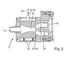
- FIG. 3 shows a second embodiment of the device 10 according to the invention, in which the switching valve 28 is designed as a slide 50, whose axis 36 as a plunger 52, the housing 16 passes through at this plunger 52 also engages a (not shown) drive and moves the slider 50th in the direction of the double arrow 54, whereby the passage 30 the inlet 18th either connects (via port 20) to the nozzle 22 or to the further outlet 24.
- a drive for example, a magnetic drive can be used, which displaces the slider 30 in the direction of return springs 56.
- the plunger 52 may also be arranged on the side of the slider 50 on which in the FIG. 3 the return springs 56 are located and these would then be on the opposite side. Then the inlet 18 would be connected to the further outlet 24 in the rest position of the drive.
Landscapes
- Engineering & Computer Science (AREA)
- Mechanical Engineering (AREA)
- Nozzles (AREA)
- Breeding Of Plants And Reproduction By Means Of Culturing (AREA)
- Multiple-Way Valves (AREA)
- Coating Apparatus (AREA)
- Printing Methods (AREA)
Applications Claiming Priority (1)
| Application Number | Priority Date | Filing Date | Title |
|---|---|---|---|
| DE201110084026 DE102011084026B4 (de) | 2011-10-05 | 2011-10-05 | Vorrichtung zum Aufbringen von Puder auf Druckbögen |
Publications (2)
| Publication Number | Publication Date |
|---|---|
| EP2578406A2 true EP2578406A2 (fr) | 2013-04-10 |
| EP2578406A3 EP2578406A3 (fr) | 2015-02-25 |
Family
ID=46967982
Family Applications (1)
| Application Number | Title | Priority Date | Filing Date |
|---|---|---|---|
| EP12183967.4A Withdrawn EP2578406A3 (fr) | 2011-10-05 | 2012-09-12 | Dispositif d'application de poudre sur des feuilles d'impression |
Country Status (2)
| Country | Link |
|---|---|
| EP (1) | EP2578406A3 (fr) |
| DE (1) | DE102011084026B4 (fr) |
Families Citing this family (2)
| Publication number | Priority date | Publication date | Assignee | Title |
|---|---|---|---|---|
| CN115674896A (zh) | 2021-07-29 | 2023-02-03 | 海德堡印刷机械股份公司 | 撒粉末装置 |
| DE102023131357A1 (de) * | 2023-11-10 | 2025-05-15 | Gema Switzerland Gmbh | Pulverversorgungsvorrichtung für eine pulverbeschichtungsanlage und verfahren zum fördern von beschichtungspulver |
Citations (4)
| Publication number | Priority date | Publication date | Assignee | Title |
|---|---|---|---|---|
| DE442790C (de) | 1924-08-22 | 1927-04-08 | August Assfalg | Briefkasten mit elektrischer Einwurfmeldung |
| DE1252703B (de) | 1963-07-13 | 1967-10-26 | Weitmann & Konrad | Vorrichtung zum Bestaeuben bewegter Druckbogen |
| US3527412A (en) | 1967-09-05 | 1970-09-08 | Binks Mfg Co | Disperser for powdered spray system |
| DE19901245A1 (de) | 1998-02-17 | 1999-08-19 | Heidelberger Druckmasch Ag | Vorrichtung zum Pudern bedruckter Bogen |
Family Cites Families (13)
| Publication number | Priority date | Publication date | Assignee | Title |
|---|---|---|---|---|
| GB529255A (en) * | 1938-08-09 | 1940-11-18 | Herbert Cole | Improvement in dry spray for preventing offset |
| GB726793A (en) * | 1951-07-12 | 1955-03-23 | Karl Otte | Improvements in or relating to pressure sprayers in printing machines to prevent theset off of fresh printed sheets when leaving the machine |
| US2901179A (en) * | 1954-11-02 | 1959-08-25 | Schnellpressenfab Heidelberg | Printing press |
| DE1037470B (de) * | 1954-11-02 | 1958-08-28 | Schnellressenfab Heidelberg | Druckmaschine mit Einrichtung zum Verhueten des Abschmierens der bedruckten Papierbogen oder -bahnen |
| CH361583A (de) * | 1958-09-10 | 1962-04-30 | Rutishauser Edgar | Druckluftanlage an Rotations-Trommel-Vervielfältigern |
| DE2527903C3 (de) | 1975-06-23 | 1980-06-12 | Anibal Armando Prof. Dr. Brasilia Inocencio | Elektrochemisches Element |
| CS204450B1 (en) * | 1978-12-27 | 1981-04-30 | Vaclav Kaspar | Dusting device |
| JPH04345848A (ja) * | 1991-05-23 | 1992-12-01 | Dainippon Printing Co Ltd | オフセット印刷におけるオゾン排気方法および排気装置 |
| DE4427904A1 (de) * | 1994-08-06 | 1996-02-08 | Hans Platsch | Puderbestäubungsgerät |
| DE19707157B4 (de) * | 1997-02-22 | 2006-04-06 | Weitmann & Konrad Gmbh & Co Kg | Vorrichtung zum Bestäuben von bewegten flächigen Produkten |
| DE10361602A1 (de) * | 2003-12-24 | 2005-07-21 | Platsch Gmbh & Co.Kg | Pudergasgenerator |
| DE102005050199A1 (de) * | 2005-10-18 | 2007-04-19 | Platsch Gmbh & Co.Kg | Vorrichtung zum Bestäuben von Produkten, insbesondere Druckprodukten |
| CN102189753B (zh) * | 2010-03-15 | 2015-03-18 | 海德堡印刷机械股份公司 | 用于对印刷页张撒布粉末的设备 |
-
2011
- 2011-10-05 DE DE201110084026 patent/DE102011084026B4/de active Active
-
2012
- 2012-09-12 EP EP12183967.4A patent/EP2578406A3/fr not_active Withdrawn
Patent Citations (4)
| Publication number | Priority date | Publication date | Assignee | Title |
|---|---|---|---|---|
| DE442790C (de) | 1924-08-22 | 1927-04-08 | August Assfalg | Briefkasten mit elektrischer Einwurfmeldung |
| DE1252703B (de) | 1963-07-13 | 1967-10-26 | Weitmann & Konrad | Vorrichtung zum Bestaeuben bewegter Druckbogen |
| US3527412A (en) | 1967-09-05 | 1970-09-08 | Binks Mfg Co | Disperser for powdered spray system |
| DE19901245A1 (de) | 1998-02-17 | 1999-08-19 | Heidelberger Druckmasch Ag | Vorrichtung zum Pudern bedruckter Bogen |
Also Published As
| Publication number | Publication date |
|---|---|
| EP2578406A3 (fr) | 2015-02-25 |
| DE102011084026A1 (de) | 2013-04-11 |
| DE102011084026B4 (de) | 2015-04-02 |
Similar Documents
| Publication | Publication Date | Title |
|---|---|---|
| DE102011012290A1 (de) | Vorrichtung zum Bestäuben von Druckbogen mit Puder | |
| DE1252703B (de) | Vorrichtung zum Bestaeuben bewegter Druckbogen | |
| DE102009007800A1 (de) | Aerosol-Drucker, dessen Verwendung und Verfahren zur Herstellung von Linienunterbrechungen bei kontinuierlichen Aerosol-Druckverfahren | |
| EP1914004B1 (fr) | Procédé de commande d'un pulvérisateur de poudre | |
| EP0121675A2 (fr) | Machine à imprimer avec dispositif de laquage pour feuilles | |
| DE102011084026B4 (de) | Vorrichtung zum Aufbringen von Puder auf Druckbögen | |
| DE102019101930A1 (de) | Pulverabgabevorrichtung mit einer Pulverdünnstrompumpe | |
| EP3148709B1 (fr) | Cabine de pulvérisation de poudre | |
| DE19937090B4 (de) | Verfahren und Vorrichtung zum Bestäuben von bedruckten Bogen | |
| DE3217779C2 (fr) | ||
| DE102017219710A1 (de) | Verfahren zum Besprühen von Druckbogen mit Puder | |
| EP3313584B1 (fr) | Bloc changeur de poudre et système de distribution de poudre pourvu dudit bloc changeur de poudre | |
| EP0850694B1 (fr) | Vanne pour un dispositif de revêtement ayant au moins deux conduits de fluide | |
| EP0603647A1 (fr) | Dispositif pour la fabrication en continu de bandes en mousse plastique, notamment de plaques de mousse à haute résistance | |
| WO2003041461A2 (fr) | Procede et dispositif pour traiter des objets a l'aide d'un liquide | |
| DE102007047554B3 (de) | Verfahren zur Reinigung der Aperturen von Druckmasken sowie Düsenkopf zur Durchführung dieses Verfahrens | |
| DE102017101370A1 (de) | Vorrichtung zum Vernebeln einer Spülflüssigkeit | |
| DE102013205783B4 (de) | Vorrichtung zum Aufbringen von Puder auf Druckbögen | |
| EP0880999B1 (fr) | Dispositif et procédé d'encollage transversal de produits imprimés | |
| EP0410400B1 (fr) | Dispositif pour l'alimentation en matériau de plieuses et dispositifs de mouillage dans des machines à imprimer | |
| EP1777070A2 (fr) | Appareil de poudrage de substrats, en particulier de substrats imprimés | |
| DE102014015702A1 (de) | Hochrotationszerstäuber | |
| WO2025093418A1 (fr) | Dispositif de commutation de poudre pour alimenter sélectivement différents types et/ou genres de poudre vers un dispositif d'évacuation de poudre | |
| DE19807974C1 (de) | Spritzvorrichtung zum Zerstäuben von Flüssigkeiten | |
| DE2536007C2 (de) | Leimsprühdüse |
Legal Events
| Date | Code | Title | Description |
|---|---|---|---|
| PUAI | Public reference made under article 153(3) epc to a published international application that has entered the european phase |
Free format text: ORIGINAL CODE: 0009012 |
|
| AK | Designated contracting states |
Kind code of ref document: A2 Designated state(s): AL AT BE BG CH CY CZ DE DK EE ES FI FR GB GR HR HU IE IS IT LI LT LU LV MC MK MT NL NO PL PT RO RS SE SI SK SM TR |
|
| AX | Request for extension of the european patent |
Extension state: BA ME |
|
| PUAL | Search report despatched |
Free format text: ORIGINAL CODE: 0009013 |
|
| AK | Designated contracting states |
Kind code of ref document: A3 Designated state(s): AL AT BE BG CH CY CZ DE DK EE ES FI FR GB GR HR HU IE IS IT LI LT LU LV MC MK MT NL NO PL PT RO RS SE SI SK SM TR |
|
| AX | Request for extension of the european patent |
Extension state: BA ME |
|
| RIC1 | Information provided on ipc code assigned before grant |
Ipc: B41F 23/06 20060101AFI20150119BHEP |
|
| STAA | Information on the status of an ep patent application or granted ep patent |
Free format text: STATUS: THE APPLICATION IS DEEMED TO BE WITHDRAWN |
|
| 18D | Application deemed to be withdrawn |
Effective date: 20150826 |