EP0850694B1 - Vanne pour un dispositif de revêtement ayant au moins deux conduits de fluide - Google Patents
Vanne pour un dispositif de revêtement ayant au moins deux conduits de fluide Download PDFInfo
- Publication number
- EP0850694B1 EP0850694B1 EP97120051A EP97120051A EP0850694B1 EP 0850694 B1 EP0850694 B1 EP 0850694B1 EP 97120051 A EP97120051 A EP 97120051A EP 97120051 A EP97120051 A EP 97120051A EP 0850694 B1 EP0850694 B1 EP 0850694B1
- Authority
- EP
- European Patent Office
- Prior art keywords
- fluid
- slide
- channel
- fluid channel
- spray
- Prior art date
- Legal status (The legal status is an assumption and is not a legal conclusion. Google has not performed a legal analysis and makes no representation as to the accuracy of the status listed.)
- Expired - Lifetime
Links
- 239000012530 fluid Substances 0.000 title claims description 134
- 238000005507 spraying Methods 0.000 title claims description 17
- 239000007921 spray Substances 0.000 claims description 55
- 238000000576 coating method Methods 0.000 claims description 34
- 239000011248 coating agent Substances 0.000 claims description 32
- 239000000463 material Substances 0.000 claims description 29
- 230000008878 coupling Effects 0.000 claims 1
- 238000010168 coupling process Methods 0.000 claims 1
- 238000005859 coupling reaction Methods 0.000 claims 1
- 238000007493 shaping process Methods 0.000 description 12
- 230000006835 compression Effects 0.000 description 5
- 238000007906 compression Methods 0.000 description 5
- 239000007788 liquid Substances 0.000 description 3
- 230000004323 axial length Effects 0.000 description 2
- 230000001934 delay Effects 0.000 description 2
- 238000000034 method Methods 0.000 description 2
- 230000001105 regulatory effect Effects 0.000 description 2
- 238000011144 upstream manufacturing Methods 0.000 description 2
- 238000000889 atomisation Methods 0.000 description 1
- 230000005540 biological transmission Effects 0.000 description 1
- 239000004020 conductor Substances 0.000 description 1
- 230000000694 effects Effects 0.000 description 1
- 230000001939 inductive effect Effects 0.000 description 1
- 230000003287 optical effect Effects 0.000 description 1
- 239000002245 particle Substances 0.000 description 1
- 239000000843 powder Substances 0.000 description 1
- 230000036316 preload Effects 0.000 description 1
- 239000000565 sealant Substances 0.000 description 1
- 238000007789 sealing Methods 0.000 description 1
Images


Classifications
-
- B—PERFORMING OPERATIONS; TRANSPORTING
- B05—SPRAYING OR ATOMISING IN GENERAL; APPLYING FLUENT MATERIALS TO SURFACES, IN GENERAL
- B05B—SPRAYING APPARATUS; ATOMISING APPARATUS; NOZZLES
- B05B5/00—Electrostatic spraying apparatus; Spraying apparatus with means for charging the spray electrically; Apparatus for spraying liquids or other fluent materials by other electric means
- B05B5/002—Electrostatic spraying apparatus; Spraying apparatus with means for charging the spray electrically; Apparatus for spraying liquids or other fluent materials by other electric means comprising means for neutralising the spray of charged droplets or particules
- B05B5/003—Electrostatic spraying apparatus; Spraying apparatus with means for charging the spray electrically; Apparatus for spraying liquids or other fluent materials by other electric means comprising means for neutralising the spray of charged droplets or particules by mixing two sprays of opposite polarity
-
- B—PERFORMING OPERATIONS; TRANSPORTING
- B05—SPRAYING OR ATOMISING IN GENERAL; APPLYING FLUENT MATERIALS TO SURFACES, IN GENERAL
- B05B—SPRAYING APPARATUS; ATOMISING APPARATUS; NOZZLES
- B05B7/00—Spraying apparatus for discharge of liquids or other fluent materials from two or more sources, e.g. of liquid and air, of powder and gas
- B05B7/02—Spray pistols; Apparatus for discharge
- B05B7/12—Spray pistols; Apparatus for discharge designed to control volume of flow, e.g. with adjustable passages
- B05B7/1254—Spray pistols; Apparatus for discharge designed to control volume of flow, e.g. with adjustable passages the controlling means being fluid actuated
- B05B7/1263—Spray pistols; Apparatus for discharge designed to control volume of flow, e.g. with adjustable passages the controlling means being fluid actuated pneumatically actuated
-
- F—MECHANICAL ENGINEERING; LIGHTING; HEATING; WEAPONS; BLASTING
- F16—ENGINEERING ELEMENTS AND UNITS; GENERAL MEASURES FOR PRODUCING AND MAINTAINING EFFECTIVE FUNCTIONING OF MACHINES OR INSTALLATIONS; THERMAL INSULATION IN GENERAL
- F16K—VALVES; TAPS; COCKS; ACTUATING-FLOATS; DEVICES FOR VENTING OR AERATING
- F16K11/00—Multiple-way valves, e.g. mixing valves; Pipe fittings incorporating such valves
- F16K11/02—Multiple-way valves, e.g. mixing valves; Pipe fittings incorporating such valves with all movable sealing faces moving as one unit
- F16K11/06—Multiple-way valves, e.g. mixing valves; Pipe fittings incorporating such valves with all movable sealing faces moving as one unit comprising only sliding valves, i.e. sliding closure elements
- F16K11/065—Multiple-way valves, e.g. mixing valves; Pipe fittings incorporating such valves with all movable sealing faces moving as one unit comprising only sliding valves, i.e. sliding closure elements with linearly sliding closure members
- F16K11/07—Multiple-way valves, e.g. mixing valves; Pipe fittings incorporating such valves with all movable sealing faces moving as one unit comprising only sliding valves, i.e. sliding closure elements with linearly sliding closure members with cylindrical slides
- F16K11/0712—Multiple-way valves, e.g. mixing valves; Pipe fittings incorporating such valves with all movable sealing faces moving as one unit comprising only sliding valves, i.e. sliding closure elements with linearly sliding closure members with cylindrical slides comprising particular spool-valve sealing means
-
- B—PERFORMING OPERATIONS; TRANSPORTING
- B05—SPRAYING OR ATOMISING IN GENERAL; APPLYING FLUENT MATERIALS TO SURFACES, IN GENERAL
- B05B—SPRAYING APPARATUS; ATOMISING APPARATUS; NOZZLES
- B05B1/00—Nozzles, spray heads or other outlets, with or without auxiliary devices such as valves, heating means
- B05B1/30—Nozzles, spray heads or other outlets, with or without auxiliary devices such as valves, heating means designed to control volume of flow, e.g. with adjustable passages
- B05B1/3033—Nozzles, spray heads or other outlets, with or without auxiliary devices such as valves, heating means designed to control volume of flow, e.g. with adjustable passages the control being effected by relative coaxial longitudinal movement of the controlling element and the spray head
- B05B1/304—Nozzles, spray heads or other outlets, with or without auxiliary devices such as valves, heating means designed to control volume of flow, e.g. with adjustable passages the control being effected by relative coaxial longitudinal movement of the controlling element and the spray head the controlling element being a lift valve
- B05B1/3046—Nozzles, spray heads or other outlets, with or without auxiliary devices such as valves, heating means designed to control volume of flow, e.g. with adjustable passages the control being effected by relative coaxial longitudinal movement of the controlling element and the spray head the controlling element being a lift valve the valve element, e.g. a needle, co-operating with a valve seat located downstream of the valve element and its actuating means, generally in the proximity of the outlet orifice
- B05B1/306—Nozzles, spray heads or other outlets, with or without auxiliary devices such as valves, heating means designed to control volume of flow, e.g. with adjustable passages the control being effected by relative coaxial longitudinal movement of the controlling element and the spray head the controlling element being a lift valve the valve element, e.g. a needle, co-operating with a valve seat located downstream of the valve element and its actuating means, generally in the proximity of the outlet orifice the actuating means being a fluid
-
- B—PERFORMING OPERATIONS; TRANSPORTING
- B05—SPRAYING OR ATOMISING IN GENERAL; APPLYING FLUENT MATERIALS TO SURFACES, IN GENERAL
- B05B—SPRAYING APPARATUS; ATOMISING APPARATUS; NOZZLES
- B05B12/00—Arrangements for controlling delivery; Arrangements for controlling the spray area
-
- B—PERFORMING OPERATIONS; TRANSPORTING
- B05—SPRAYING OR ATOMISING IN GENERAL; APPLYING FLUENT MATERIALS TO SURFACES, IN GENERAL
- B05B—SPRAYING APPARATUS; ATOMISING APPARATUS; NOZZLES
- B05B7/00—Spraying apparatus for discharge of liquids or other fluent materials from two or more sources, e.g. of liquid and air, of powder and gas
- B05B7/02—Spray pistols; Apparatus for discharge
- B05B7/08—Spray pistols; Apparatus for discharge with separate outlet orifices, e.g. to form parallel jets, i.e. the axis of the jets being parallel, to form intersecting jets, i.e. the axis of the jets converging but not necessarily intersecting at a point
- B05B7/0807—Spray pistols; Apparatus for discharge with separate outlet orifices, e.g. to form parallel jets, i.e. the axis of the jets being parallel, to form intersecting jets, i.e. the axis of the jets converging but not necessarily intersecting at a point to form intersecting jets
- B05B7/0815—Spray pistols; Apparatus for discharge with separate outlet orifices, e.g. to form parallel jets, i.e. the axis of the jets being parallel, to form intersecting jets, i.e. the axis of the jets converging but not necessarily intersecting at a point to form intersecting jets with at least one gas jet intersecting a jet constituted by a liquid or a mixture containing a liquid for controlling the shape of the latter
Definitions
- the invention relates to a Spray coating device according to the preamble of claim 1.
- a spray coating device is known from US 3,841,555.
- From DE 22 09 896 C2 is one Spray coating device known with which liquid coating material towards you coating object can be sprayed.
- the Coating material flows through a valve, whose valve body has a needle-like shape a spray nozzle on which the atomizing process through compressed air, so-called atomizing air, is supported.
- the spray jet has a round one Cross-sectional shape.
- the needle-shaped valve body can be switched on the coating material flow through a Trigger guard operated by hand when the Spray device is a hand-held spray gun, or by compressed air against the force of a spring be operated if it is an automatic Spray device is.
- the Coating material flow-also through one Rotary atomizer element or other technique be sprayed.
- the operating air flows can then only individually to be regulated when in the sprayer separate lines are supplied. Since that Control unit, which the operating air flows and the Actuating air controls over a relatively long time Lines and large distance from the Spray device is arranged, for example in an electrical control cabinet or in the control section of a robot, there are long delay times until the air in question from the control unit to Spray device arrives.
- a spray device is not just at the beginning and End of a working day but during a Working day turned on hundreds of times and turned off because of the coating process between the different ones to be coated Objects always switched off and then again must be switched on.
- the objects are usually from automatic transportation systems passed a spray station where one or several spray devices.
- a stream of compressed air is only in the Spray device divided into operating air flows is, for example, to an atomizing air flow and a shaping air flow, then at the Spray device by adjusting the Flow rate of the atomizing air and the Forming air can be adjusted, their pressures are but not adjustable independently.
- the object of the invention is to be achieved to create a way through which a Spraying lumps of coating material onto the object to be coated when switched on and on Dripping of coating material on the Avoid spray device when turned off become; through which the different air flows and turning on and off the Coating material separately can be controlled or regulated without extensive, expensive control devices or Multi-valve arrangements are required; and through what response delays as a result of long Fluid lines when switching on and off be avoided.
- Fluid flows Material flows can be used, they will hereinafter referred to as "fluid flows" designated.
- Fluid flows Through the invention, everyone Fluid flows through the pressure of one of these Fluid flows in the new valve device controlled without electromagnetic or electropneumatic multi-valve devices or complex control circuits are required.
- the Valve device can directly according to the invention be arranged on the spray device so that the fluid flows it controls without Time delay on the sprayer effective can be. All fluid flows can Spray device can be fed individually.
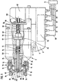
- Fig. 1 is a spray coating device shown with a spray device 2, which on a carrier 4 by means of a rotary latch 6 is mounted.
- a spray device 2 can Spray device 2 on a robot, lifting stand, Handle or other carrier (not shown) be grown.
- the spray device is from a control unit 9 controlled, which on one of its remote location is located for example in the control section of a robot or in a control cabinet.
- the spray device can be used to spray liquid or powder coating material be trained.
- Fig. 1 shows in axial section as Example a spray device 2 for Coating liquid.
- a nozzle head 10 of the Spray device 2 contains a separating ring 12 and a nozzle element 14, which has a fluid channel 20 for Shaping air 30 and a fluid channel 22 for Atomizing air 32 separates from each other.
- projections or horns 34 of an air distributor 16 form that End of the shaping air fluid channel 20 and direct the Forming air 30 on the atomized Coating material jet 36 to get it from a round to shape into a flat cross-sectional shape.
- High voltage electrodes 38 for electrostatic The coating material can be charged in or next to the air flow of the shaping air 30 or be arranged in a suitable other place.
- a Union nut 18 holds the elements on one Housing 40 of the spray device 2.
- the coating material is replaced by a Fluid channel 24 of a central spray opening 42 on Nozzle element 14 supplied and sprayed there when through a valve needle 44 from a valve seat 46 an actuator 48 against the Spring force of a biasing spring 50 is lifted off.
- This spray nozzle valve 44, 46 is by the Bias spring 50 closed and can counter be opened by their spring force Actuating compressed air if this Actuating air from the control unit 9 via a Actuating air fluid channel 26 into a pressure chamber 51 is passed and there a piston 52 of the Actuator 48 against Preload spring 50 moves to the right.
- the Valve needle 44 and the piston 52 are replaced by a further spring 54 axially held together so that they are moved axially together. at closed spray nozzle valve 44, 46 can do that Coating material through a fluid channel 28 be recirculated.
- a sensor 62 is attached to the adapter 8, which with one attached to the piston 52 Sensor pin 56 mechanical, inductive, capacitive or interacts optically and thereby the Axial positions of the valve needle 44, and thus also the open or closed position of the Spray nozzle valve 44, 46 recognizes and over a Telecommunication route 64, e.g. electrical or optical conductors or a wireless transmission path reports the control unit 9.
- a Telecommunication route 64 e.g. electrical or optical conductors or a wireless transmission path reports the control unit 9.
- the objects to be coated are usually from a transport device automatically on the spray device 2 past.
- the supply of the Coating material switched off so that Coating material does not pass the objects is injected into the environment. This means that Coating device during a working day switched on and off very often. If the individual fluid channels 20, 22, 24, 26 and 28 switched on for this purpose in the control unit 9 and switched off, you have a very long time Fluid channel paths through which Response delays arise.
- the valve device 70 is close to this disadvantage arranged on or in the spray device 2, preferably in the adapter 8.
- Die Valve device 70 also has the large one Advantage that they have the spray nozzle valve 44, 46th only opens if already Atomizing air 32 and shaping air 30 from the Spray device 2 emerge, or vice versa First, the spray nozzle valve 44, 46 closes before the atomizing air and the shaping air off. This will surely turn everything into Spray nozzle valve 44, 46 exiting Coating material sprayed properly and it cannot drop in the direction of that object to be coated or as a drop fall off.
- the valve device 70 has the other Advantage that the compressed air it controls, which actuates the spray nozzle valve 44, 46, too the valve device 70 is actuated without this an expensive electromagnetic multi-valve arrangement or an expensive computer control in the Control device 9 is required.
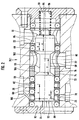
- the valve device 70.1 is shown in FIG Closed position and in Fig. 3 in the open position shown, between which a valve slide 74 in a slide guide channel 76 of a valve housing 72 by a distance "x" in Slider longitudinal direction is axially displaceable.
- the Slider 74 is against the wall of the guide channel 76 by sealing means, e.g. O-rings 69 sealed.
- a section of the actuation air duct 26 leads through one in the guide channel 76 formed control pressure chamber 88, in which the pressure the actuating air for the spray nozzle valve 44, 46 the slide 74 against the force of a compression spring 86 from the closed position in FIG. 2 to the open position 3 can move axially.
- the pressure of the actuating air drops Slider 74 by the spring 86 from the open position in Fig. 3 moved back to the closed position of Fig. 2.
- the control pressure chamber 88 is between one Slider face 90 and an inner housing face 92 at one end of slide 74 educated.
- the compression spring 86 is at the other Slide end opposite between one directed slide face 91 and one of her opposite inner housing end face 93 clamped.
- the axial movements of the slide 74 are limited by stops 94 and 95.
- the guide channel 76 has in the housing 72 in the area of the control pressure chamber 88 a fluid inlet 78 and a fluid outlet 82 of the actuation air channel 26.
- the fluid inlet 78 is in any axial position of the slide 74 open to the control pressure chamber 88 and could therefore instead be shown in the Sidewall also in the housing end face 92 be formed, which in all axial positions the slide 74 of the slide face 90 with opposite axial distance and the control pressure chamber 88 limited. Because of this distance ensured that the actuating compressed air through their fluid inlet 78 at all axial Slider positions in the control pressure chamber 88 can reach.
- the fluid outlet 82 of the Actuating air duct 26 has a larger axial Distance as the fluid inlet 78 from the Control pressure space 88 delimiting slide face 90 arranged, based on that in FIG Shown closed position of the slide 74th
- spray devices 2 without atomizing air and with or without Forming air work, or with air, which over Outer surfaces of the spray device 2 flow around them to keep clean.
- the fluid inlet 80 and Fluid outlet 84 of the atomizing air channel have one smaller axial distance "y" from each other than that Fluid outlet 82 from the fluid inlet 78 of the Actuating air duct 26.
- the one in slide 74 formed connecting portion 98 has a Fluid outlet 84 of the atomizing air channel 22 axially closer end 102 and one axially towards towards the piston end face 90 of the control pressure chamber axially further distal end 104. These two Ends 102 and 104 are axially far apart, that the connecting portion 98 at all axial Positions of slide 74 with fluid inlet 80 of the atomizer air duct 22 in terms of flow connected is.
- the fluid outlet 84 as the fluid inlet, and the Fluid inlet 80 as a fluid outlet further Serve fluid channel 22, i.e. their line connections of the fluid channel 22 can be interchanged.
- the connecting portion 98 is preferred 2 and 3 one in the slide 74th formed annular groove, the axial length between their end faces 102 and 104 is at least as large like the short distance "y" plus the axial Width of fluid inlet 80 and / or Fluid outlet 84 of the associated fluid channel 22.
- a bypass 106 is a narrow throttle channel formed and connects the fluid outlet 82 of the Actuating air duct 26 bypassing the Slider 74 in all axial slide positions with the control pressure chamber 88. This can this fluid outlet 82 is the pressure of the actuating air Dismantle into the control pressure chamber 88 if this fluid outlet 82 of the actuating air channel 26 is closed by the slide 64 when this from the open position of Fig. 3 in the 2 is moved axially.
- FIGS. 1 and 2 show a further embodiment 70.2 of the Valve device.
- it corresponds to Embodiment according to FIGS. 1 and 2, which is why Identical parts with the same reference numbers are.
- the main difference is that in addition to the actuating air duct 26 not just one more, but two more fluid channels passed through them in the present Example of atomizer air duct 22 and Forming air duct 20.
- the axial movement path of the Slider 74 for connecting and disconnecting the Fluid inlet 80 and the fluid outlet 84 of the Atomizer air duct 22 is labeled "y1"
- the axial movement path of the slide 74 for Connect or disconnect the fluid inlet 79 from the Fluid outlet 83 of the shaping air duct 20 is with designated "y2".
- the axial lengths of the two Movement paths "y1" and “y2" can be the same or be different and are each much shorter than the axial travel "x" of the slider 74. for connecting or disconnecting the fluid inlet 78 and the actuating air duct fluid outlet 82 26 with each other or from each other.
- the one in slide 74 formed connecting section of the The shaping air duct 20 is 101 in FIG. 4 designated.
- the fluid inlet 80 can Fluid outlet 84 of the atomizer air channel 22 diametrically opposite to the guide channel 76, and fluid inlet 79 may be fluid outlet 83 diametrically opposite.
- one Valve device 70.3 according to FIGS. 5 and 6 two valve devices according to FIGS. 2 and 3 arranged in parallel next to each other, one for the Atomizer air duct 22 and one for the Forming air duct 20 of Fig. 4.
- Your Control pressure spaces 88 are fluid connected in parallel, the fluid inlets 78 on upstream branch of the actuation air duct 26 are interconnected, and the fluid outlets 82 on the downstream branch of the Actuating air duct 26 connected to each other are.
- Double valve device shown in the open position 70.4 are two slides 74 opposite to each other in a common Guide channel 76 arranged such that they have a have common control pressure chamber 88, the axial on both sides of a slide face 90 one of the two sliders 74 is axially limited.
- the compression springs 86 are on the opposite outer protruding End faces 91 of the slider 74 arranged.
- the Control pressure chamber 88 has only one Fluid inlet 78 on the upstream side of the Actuating air duct 26, but two fluid outlets 82 on the downstream side of the Actuating air duct 26, each one is assigned to another of the two slides 74.
- in the is the axial region of the right control spool 74 a fluid inlet 80 and a fluid outlet 84 of the Atomizer air duct 22 formed in the housing 72, between which of these sliders 74 and the housing 72 form a valve 120, which is from the right Slider 74 is opened before the Passage between fluid inlet 78 and fluid outlet 82 of the actuating air channel 26 opens when it is from the closed position shown in Fig. 7 to the right moved to the open position shown in Fig. 8 becomes.
- valve devices 70.1, 70.2, 70.3 and 70.4 can not only for spray devices, but also for other facilities and purposes other than the described are used.
Landscapes
- Engineering & Computer Science (AREA)
- General Engineering & Computer Science (AREA)
- Mechanical Engineering (AREA)
- Nozzles (AREA)
- Spray Control Apparatus (AREA)
Claims (10)
- Appareil de revêtement par pulvérisation comportant un dispositif de pulvérisation et au moins deux voies de fluide reliées à ce dispositif, et dans lequel au moins deux des voies de fluide (26, 22 ; 26, 22, 20) traversent un distributeur (70) qui présente un tiroir (74) dans un canal de guidage (76) pour l'ouverture et la fermeture de ces voies de fluide,
caractérisé par le fait qu'une partie d'une première voie de fluide (26) de ces voies de fluide est un espace à pression de pilotage (88) formé dans le canal de guidage (76) et dans lequel la pression d'un fluide de la première voie de fluide (26) peut déplacer le tiroir (74) d'une position fermée à une position ouverte contre l'action d'un moyen élastique (86),
que l'espace à pression de pilotage (88) est limité dans la direction longitudinale du tiroir d'une part par une face frontale (90) du tiroir commandée par fluide et d'autre part par une face opposée (90, 92) séparée du tiroir (74),
que l'espace à pression de pilotage (88) présente dans un corps (72) du canal de guidage (76) une entrée de fluide (78) et une sortie de fluide (82) de la première voie de fluide (26), par laquelle, dans toute position du tiroir (74), l'entrée de fluide (78) est ouverte vers la face frontale (90) du tiroir commandée par fluide, tandis que le tiroir (74), en position fermée, obture la sortie de fluide (82) et, en position ouverte, dégage la sortie de fluide (82) vers l'espace à pression de pilotage (88),
que lorsque le tiroir (74) est en position fermée, la distance entre la face frontale (90) du tiroir commandée par fluide et la sortie de fluide (82) de la première voie de fluide (26) est supérieure à la distance entre une partie de liaison (98), traversant le tiroir (74), d'au moins d'une deuxième voie de fluide (22, 20) des voies de fluide et une entrée de fluide (80, 79) et/ou une sortie de fluide (84, 83), formée dans le canal de guidage (76), de cette deuxième voie de fluide (22, 20), de façon telle qu'en cas de mouvement du tiroir (74) de sa position fermée à sa position ouverte soient ouvertes d'abord la deuxième voie de fluide (22, 20) et ensuite la première voie de fluide (26), tandis qu'en cas de mouvement inverse du tiroir (74) de sa position ouverte à sa position fermée soient fermées d'abord la première voie de fluide (26) et ensuite la deuxième voie de fluide (22, 20). - Appareil de revêtement par pulvérisation selon la revendication 1, caractérisé par le fait que la partie de liaison (98) présente des évidements formés sur le pourtour du tiroir (74) qui, dans la direction longitudinale du tiroir, sont plus longs que l'entrée de fluide (80, 79) et/ou la sortie de fluide (84, 83) de la deuxième voie de fluide (22, 20).
- Appareil de revêtement par pulvérisation selon l'une des revendications précédentes, caractérisé par le fait que le moyen élastique (86) est placé à l'extrémité du tiroir (74) opposée à la face frontale (90) du tiroir commandée par pression de fluide.
- Appareil de revêtement par pulvérisation selon l'une des revendications précédentes, caractérisé par le fait que dans le tiroir (74) sont prévues au moins deux parties de liaison (98) pour la liaison ou la séparation d'entrées de fluide (80, 79) et de sorties de fluide (84, 83) d'au moins deux des deuxièmes voies de fluide (22, 20).
- Appareil de revêtement par pulvérisation selon l'une des revendications précédentes, caractérisé par le fait que la face opposée est une face frontale (92) du corps (72).
- Appareil de revêtement par pulvérisation selon l'une des revendications 1 à 4, caractérisé par le fait que la face opposée est une face frontale (90) commandée par pression de fluide d'un autre tiroir (74) qui est opposé au premier tiroir (74) et est par là commandé par le même fluide de la première voie de fluide (26) dans l'espace à pression de pilotage (88) contre l'action d'un autre moyen élastique (86) pour ouvrir au moins une deuxième voie de fluide (22, 20) avant la première voie de fluide (26) et fermer celle-ci après la première voie de fluide (26).
- Appareil de revêtement par pulvérisation selon l'une des revendications précédentes, caractérisé par le fait qu'il est prévu au moins deux espaces à pression de pilotage (88) qui sont limités chacun par au moins un tiroir (74) de la manière précitée, que la première voie de fluide (26) traverse par des parties de voie parallèles (78) tous les espaces à pression de pilotage (88), qui ont chacun une entrée de fluide (78) et une sortie de fluide (82) pour chacune de ces parties parallèles de la première voie de fluide (26).
- Appareil de revêtement par pulvérisation selon l'une des revendications précédentes, caractérisé par le fait que le distributeur est monté dans un adaptateur (8) par lequel le dispositif de pulvérisation (2) peut être fixé à un support.
- Appareil de revêtement par pulvérisation selon la revendication 8, caractérisé par le fait que le dispositif de pulvérisation (2) et l'adaptateur (8) peuvent être assemblés de manière démontable par un dispositif d'assemblage rapide (6).
- Appareil de revêtement par pulvérisation selon l'une des revendications précédentes, caractérisé par le fait que la première voie de fluide (26) est reliée en aval de sa sortie de fluide (82) à un espace sous pression (51) pour la manoeuvre pneumatique d'une soupape à matière de revêtement (44, 46) qui est montée dans le dispositif de pulvérisation (2) et, pour la libération ou l'interruption d'un courant de matière de revêtement, peut être manoeuvrée par de l'air comprimé de la première voie de fluide (26).
Applications Claiming Priority (2)
| Application Number | Priority Date | Filing Date | Title |
|---|---|---|---|
| DE19654514 | 1996-12-27 | ||
| DE19654514A DE19654514A1 (de) | 1996-12-27 | 1996-12-27 | Sprühbeschichtungseinrichtung |
Publications (2)
| Publication Number | Publication Date |
|---|---|
| EP0850694A1 EP0850694A1 (fr) | 1998-07-01 |
| EP0850694B1 true EP0850694B1 (fr) | 2003-03-05 |
Family
ID=7816316
Family Applications (1)
| Application Number | Title | Priority Date | Filing Date |
|---|---|---|---|
| EP97120051A Expired - Lifetime EP0850694B1 (fr) | 1996-12-27 | 1997-11-15 | Vanne pour un dispositif de revêtement ayant au moins deux conduits de fluide |
Country Status (3)
| Country | Link |
|---|---|
| EP (1) | EP0850694B1 (fr) |
| JP (1) | JP3923639B2 (fr) |
| DE (2) | DE19654514A1 (fr) |
Cited By (1)
| Publication number | Priority date | Publication date | Assignee | Title |
|---|---|---|---|---|
| US10024157B2 (en) | 2015-12-04 | 2018-07-17 | Joy Global Underground Mining Llc | Spray nozzle for underground roof support |
Families Citing this family (7)
| Publication number | Priority date | Publication date | Assignee | Title |
|---|---|---|---|---|
| DE19933440A1 (de) * | 1999-07-16 | 2001-01-18 | Bayer Ag | Dispergierdüse mit variablem Durchsatz |
| ITTV20010008A1 (it) * | 2001-01-17 | 2002-07-17 | Hip Srl High Ind Performance S | Testata di splmatura particolarmente per materiale termoplastico |
| DE10153142A1 (de) | 2001-10-27 | 2003-05-22 | Itw Oberflaechentechnik Gmbh | Ventilnadel, insbesondere für Spritzbeschichtungsflüssigkeit |
| DE102004024147A1 (de) * | 2004-05-14 | 2005-12-08 | L + N Plast Vertriebs Gmbh | Farbspritzpistole |
| DE202012006182U1 (de) * | 2012-06-27 | 2013-07-01 | Harald Adolf Sonnleitner | Zerstäuber zum Zerstäuben eines Beschichtungsmittels |
| AU2021219800A1 (en) * | 2020-02-14 | 2022-09-22 | Spraying Systems Co. | Three way valve controlled spraying system |
| DE102022101089A1 (de) * | 2022-01-18 | 2023-07-20 | Krautzberger Gmbh | Spritzapparat mit Vorluftsteuerung |
Family Cites Families (21)
| Publication number | Priority date | Publication date | Assignee | Title |
|---|---|---|---|---|
| DE1750348U (de) * | 1957-06-11 | 1957-08-08 | Peter Ilmberger | Spritzmaschine zum auftragen von farben, lacken und aehnlichen zerstaeubbaren stoffen auf beliebeg geformte koerper. |
| US3653599A (en) * | 1970-05-19 | 1972-04-04 | Speco Inc | Fluid spray apparatus |
| US3841555A (en) * | 1972-08-14 | 1974-10-15 | D Lilja | Spray apparatus and method |
| US3937253A (en) * | 1973-11-08 | 1976-02-10 | Lilja Duane F | Multiple fluid dispensing apparatus |
| US4365754A (en) * | 1980-06-19 | 1982-12-28 | Acheson Industries, Inc. | Spray assembly construction |
| US4380320A (en) * | 1981-02-25 | 1983-04-19 | Nordson Corporation | Electrostatic powder spray gun nozzle |
| US4426039A (en) * | 1982-01-11 | 1984-01-17 | Graco Inc. | Spray gun control valve |
| DE3238201A1 (de) * | 1982-10-15 | 1984-06-20 | Oskar Frech GmbH + Co, 7060 Schorndorf | Spruehkopf, insbesondere zum auftragen und verteilen von trennmittel auf druck- und spritzgussformen |
| US4522374A (en) * | 1983-03-03 | 1985-06-11 | Mac Valves, Inc. | Valve spool |
| DE3317449C2 (de) * | 1983-05-13 | 1986-07-03 | Ecker Maschinenbau GmbH, 6680 Neunkirchen | Sprühventil für die Gruppenbedüsung des Schildausbaues |
| US4613082A (en) * | 1984-07-06 | 1986-09-23 | Champion Spark Plug Company | Electrostatic spraying apparatus for robot mounting |
| DE3505619C2 (de) * | 1985-02-19 | 1986-12-11 | Kopperschmidt-Mueller Gmbh & Co Kg, 4800 Bielefeld | Verfahren zum Beschichten von Gegenständen und Vorrichtung zur Durchführung des Verfahrens |
| EP0243104B1 (fr) * | 1986-04-18 | 1998-07-08 | Fluid Technology Limited | Système d'injection de fluide |
| DE3644184A1 (de) * | 1986-12-23 | 1988-07-07 | Frech Oskar Gmbh & Co | Spruehkopf, insbesondere zum auftragen und verteilen von spruehmittel auf druckgiess- und gesenkschmiedeformen |
| DE3709956A1 (de) * | 1987-03-26 | 1988-10-06 | Laszlo Ferenc Dipl Ing Matefi | Universal-regulierbares zwei-fluid/luft steuer-spruehventil |
| DE3836051A1 (de) * | 1988-05-18 | 1989-11-30 | Schuetze Alfred App | Spritzvorrichtung und verfahren zur steuerung derselben |
| CA1336373C (fr) * | 1988-09-21 | 1995-07-25 | Nordson Corporation | Appareil pour la pulverisation d'adhesifs thermofusibles |
| FR2662620A1 (fr) * | 1990-05-31 | 1991-12-06 | Sames Sa | Installation de projection de produit de revetement pulverise a debit controle. |
| US5165604A (en) * | 1991-10-03 | 1992-11-24 | Copp Jr William H | Air supply and control assembly for an automatic spray gun |
| DE4242715C2 (de) * | 1991-12-17 | 2000-05-31 | Krautzberger Gmbh | Adapter mit Regelventil für automatische Material-Spritzvorrichtung |
| DE4416311A1 (de) * | 1994-05-09 | 1995-11-16 | Itw Oberflaechentechnik Gmbh | Sprühgerät-Befestigungsvorrichtung |
-
1996
- 1996-12-27 DE DE19654514A patent/DE19654514A1/de not_active Withdrawn
-
1997
- 1997-11-15 EP EP97120051A patent/EP0850694B1/fr not_active Expired - Lifetime
- 1997-11-15 DE DE59709434T patent/DE59709434D1/de not_active Expired - Lifetime
-
1998
- 1998-01-05 JP JP00054398A patent/JP3923639B2/ja not_active Expired - Lifetime
Cited By (2)
| Publication number | Priority date | Publication date | Assignee | Title |
|---|---|---|---|---|
| US10024157B2 (en) | 2015-12-04 | 2018-07-17 | Joy Global Underground Mining Llc | Spray nozzle for underground roof support |
| US10378354B2 (en) | 2015-12-04 | 2019-08-13 | Joy Global Underground Mining Llc | Spray nozzle for underground roof support |
Also Published As
| Publication number | Publication date |
|---|---|
| JP3923639B2 (ja) | 2007-06-06 |
| DE59709434D1 (de) | 2003-04-10 |
| EP0850694A1 (fr) | 1998-07-01 |
| DE19654514A1 (de) | 1998-07-02 |
| JPH10192744A (ja) | 1998-07-28 |
Similar Documents
| Publication | Publication Date | Title |
|---|---|---|
| DE4230535C2 (de) | Zweikomponenten-Spritzpistole | |
| DE102005007102B4 (de) | Anfahrventil | |
| EP1245295B1 (fr) | Système de changement de couleur pour un appareil de revêtement | |
| DE3500983A1 (de) | Elektrostatische spritzpistole | |
| DE2043789C3 (de) | Vorrichtung zum Farbspritzen einer Folge von Gegenständen | |
| DE60103281T3 (de) | Vorrichtung zum speisen eines spritzgeräts mit einem pulverlack und sprühbeschichtungsanlage mit einer solchen vorrichtung | |
| DE2548463A1 (de) | Sprueheinrichtung fuer pulvermaterialien | |
| EP2468413A2 (fr) | Dispositif et procédé destinés au revêtement d'un objet à l'aide d'un fluide | |
| WO2009060058A1 (fr) | Connexion d'une tête de pulvérisation à un bras de robot | |
| EP2361691A1 (fr) | Sélecteur pour fluides | |
| DE102021124141A1 (de) | Lackierpistole und Verfahren zum Betreiben einer Lackierpistole | |
| EP0850694B1 (fr) | Vanne pour un dispositif de revêtement ayant au moins deux conduits de fluide | |
| DE69004441T2 (de) | Modularer Beschichtungsapparat für Dosen. | |
| DE2646719B2 (de) | Spritzpistole | |
| EP3313584B1 (fr) | Bloc changeur de poudre et système de distribution de poudre pourvu dudit bloc changeur de poudre | |
| EP2554275B1 (fr) | Changeur de teinte | |
| EP0681872A2 (fr) | Dispositif de fixation d'un dispositif de pulvérisation | |
| DE19914040A1 (de) | Sprühpistolen-Roboter-Adapter | |
| DE3124125A1 (de) | Hochdruck-spruehpistole | |
| DE3931657A1 (de) | Duesentraeger | |
| DE9409788U1 (de) | Ventilanordnung | |
| EP1010469B1 (fr) | Système et procédé d'alimentation en peinture d'une installation de revêtement électrostatique | |
| EP2644281B1 (fr) | Changeur de teinte | |
| EP2578406A2 (fr) | Dispositif dýapplication de poudre sur des feuilles d'impression | |
| WO2025093418A1 (fr) | Dispositif de commutation de poudre pour alimenter sélectivement différents types et/ou genres de poudre vers un dispositif d'évacuation de poudre |
Legal Events
| Date | Code | Title | Description |
|---|---|---|---|
| PUAI | Public reference made under article 153(3) epc to a published international application that has entered the european phase |
Free format text: ORIGINAL CODE: 0009012 |
|
| 17P | Request for examination filed |
Effective date: 19971115 |
|
| AK | Designated contracting states |
Kind code of ref document: A1 Designated state(s): DE FR GB |
|
| AX | Request for extension of the european patent |
Free format text: AL;LT;LV;MK;RO;SI |
|
| AKX | Designation fees paid |
Free format text: DE FR GB |
|
| RBV | Designated contracting states (corrected) |
Designated state(s): DE FR GB |
|
| RAP1 | Party data changed (applicant data changed or rights of an application transferred) |
Owner name: ITW OBERFLAECHENTECHNIK GMBH & CO.KG |
|
| GRAH | Despatch of communication of intention to grant a patent |
Free format text: ORIGINAL CODE: EPIDOS IGRA |
|
| GRAH | Despatch of communication of intention to grant a patent |
Free format text: ORIGINAL CODE: EPIDOS IGRA |
|
| GRAA | (expected) grant |
Free format text: ORIGINAL CODE: 0009210 |
|
| AK | Designated contracting states |
Designated state(s): DE FR GB |
|
| REG | Reference to a national code |
Ref country code: GB Ref legal event code: FG4D Free format text: NOT ENGLISH |
|
| GBT | Gb: translation of ep patent filed (gb section 77(6)(a)/1977) |
Effective date: 20030305 |
|
| REF | Corresponds to: |
Ref document number: 59709434 Country of ref document: DE Date of ref document: 20030410 Kind code of ref document: P |
|
| ET | Fr: translation filed | ||
| PLBE | No opposition filed within time limit |
Free format text: ORIGINAL CODE: 0009261 |
|
| STAA | Information on the status of an ep patent application or granted ep patent |
Free format text: STATUS: NO OPPOSITION FILED WITHIN TIME LIMIT |
|
| 26N | No opposition filed |
Effective date: 20031208 |
|
| PGFP | Annual fee paid to national office [announced via postgrant information from national office to epo] |
Ref country code: DE Payment date: 20101126 Year of fee payment: 14 |
|
| PGFP | Annual fee paid to national office [announced via postgrant information from national office to epo] |
Ref country code: GB Payment date: 20101124 Year of fee payment: 14 |
|
| PGFP | Annual fee paid to national office [announced via postgrant information from national office to epo] |
Ref country code: FR Payment date: 20111128 Year of fee payment: 15 |
|
| GBPC | Gb: european patent ceased through non-payment of renewal fee |
Effective date: 20121115 |
|
| REG | Reference to a national code |
Ref country code: FR Ref legal event code: ST Effective date: 20130731 |
|
| REG | Reference to a national code |
Ref country code: DE Ref legal event code: R119 Ref document number: 59709434 Country of ref document: DE Effective date: 20130601 |
|
| PG25 | Lapsed in a contracting state [announced via postgrant information from national office to epo] |
Ref country code: DE Free format text: LAPSE BECAUSE OF NON-PAYMENT OF DUE FEES Effective date: 20130601 |
|
| PG25 | Lapsed in a contracting state [announced via postgrant information from national office to epo] |
Ref country code: FR Free format text: LAPSE BECAUSE OF NON-PAYMENT OF DUE FEES Effective date: 20121130 Ref country code: GB Free format text: LAPSE BECAUSE OF NON-PAYMENT OF DUE FEES Effective date: 20121115 |