EP2578834A1 - Wiederherstellungssteuerungssystem - Google Patents
Wiederherstellungssteuerungssystem Download PDFInfo
- Publication number
- EP2578834A1 EP2578834A1 EP11786509.7A EP11786509A EP2578834A1 EP 2578834 A1 EP2578834 A1 EP 2578834A1 EP 11786509 A EP11786509 A EP 11786509A EP 2578834 A1 EP2578834 A1 EP 2578834A1
- Authority
- EP
- European Patent Office
- Prior art keywords
- urea solution
- dosing valve
- urea
- recovery control
- supply module
- Prior art date
- Legal status (The legal status is an assumption and is not a legal conclusion. Google has not performed a legal analysis and makes no representation as to the accuracy of the status listed.)
- Granted
Links
Images




Classifications
-
- F—MECHANICAL ENGINEERING; LIGHTING; HEATING; WEAPONS; BLASTING
- F01—MACHINES OR ENGINES IN GENERAL; ENGINE PLANTS IN GENERAL; STEAM ENGINES
- F01N—GAS-FLOW SILENCERS OR EXHAUST APPARATUS FOR MACHINES OR ENGINES IN GENERAL; GAS-FLOW SILENCERS OR EXHAUST APPARATUS FOR INTERNAL-COMBUSTION ENGINES
- F01N11/00—Monitoring or diagnostic devices for exhaust-gas treatment apparatus
-
- F—MECHANICAL ENGINEERING; LIGHTING; HEATING; WEAPONS; BLASTING
- F01—MACHINES OR ENGINES IN GENERAL; ENGINE PLANTS IN GENERAL; STEAM ENGINES
- F01N—GAS-FLOW SILENCERS OR EXHAUST APPARATUS FOR MACHINES OR ENGINES IN GENERAL; GAS-FLOW SILENCERS OR EXHAUST APPARATUS FOR INTERNAL-COMBUSTION ENGINES
- F01N3/00—Exhaust or silencing apparatus having means for purifying, rendering innocuous, or otherwise treating exhaust
- F01N3/08—Exhaust or silencing apparatus having means for purifying, rendering innocuous, or otherwise treating exhaust for rendering innocuous
- F01N3/10—Exhaust or silencing apparatus having means for purifying, rendering innocuous, or otherwise treating exhaust for rendering innocuous by thermal or catalytic conversion of noxious components of exhaust
- F01N3/18—Exhaust or silencing apparatus having means for purifying, rendering innocuous, or otherwise treating exhaust for rendering innocuous by thermal or catalytic conversion of noxious components of exhaust characterised by methods of operation; Control
- F01N3/20—Exhaust or silencing apparatus having means for purifying, rendering innocuous, or otherwise treating exhaust for rendering innocuous by thermal or catalytic conversion of noxious components of exhaust characterised by methods of operation; Control specially adapted for catalytic conversion
- F01N3/206—Adding periodically or continuously substances to exhaust gases for promoting purification, e.g. catalytic material in liquid form, NOx reducing agents
- F01N3/208—Control of selective catalytic reduction [SCR], e.g. by adjusting the dosing of reducing agent
-
- B—PERFORMING OPERATIONS; TRANSPORTING
- B01—PHYSICAL OR CHEMICAL PROCESSES OR APPARATUS IN GENERAL
- B01D—SEPARATION
- B01D2251/00—Reactants
- B01D2251/20—Reductants
- B01D2251/206—Ammonium compounds
- B01D2251/2067—Urea
-
- F—MECHANICAL ENGINEERING; LIGHTING; HEATING; WEAPONS; BLASTING
- F01—MACHINES OR ENGINES IN GENERAL; ENGINE PLANTS IN GENERAL; STEAM ENGINES
- F01N—GAS-FLOW SILENCERS OR EXHAUST APPARATUS FOR MACHINES OR ENGINES IN GENERAL; GAS-FLOW SILENCERS OR EXHAUST APPARATUS FOR INTERNAL-COMBUSTION ENGINES
- F01N2550/00—Monitoring or diagnosing the deterioration of exhaust systems
- F01N2550/05—Systems for adding substances into exhaust
-
- F—MECHANICAL ENGINEERING; LIGHTING; HEATING; WEAPONS; BLASTING
- F01—MACHINES OR ENGINES IN GENERAL; ENGINE PLANTS IN GENERAL; STEAM ENGINES
- F01N—GAS-FLOW SILENCERS OR EXHAUST APPARATUS FOR MACHINES OR ENGINES IN GENERAL; GAS-FLOW SILENCERS OR EXHAUST APPARATUS FOR INTERNAL-COMBUSTION ENGINES
- F01N2610/00—Adding substances to exhaust gases
- F01N2610/02—Adding substances to exhaust gases the substance being ammonia or urea
-
- F—MECHANICAL ENGINEERING; LIGHTING; HEATING; WEAPONS; BLASTING
- F01—MACHINES OR ENGINES IN GENERAL; ENGINE PLANTS IN GENERAL; STEAM ENGINES
- F01N—GAS-FLOW SILENCERS OR EXHAUST APPARATUS FOR MACHINES OR ENGINES IN GENERAL; GAS-FLOW SILENCERS OR EXHAUST APPARATUS FOR INTERNAL-COMBUSTION ENGINES
- F01N2610/00—Adding substances to exhaust gases
- F01N2610/14—Arrangements for the supply of substances, e.g. conduits
- F01N2610/1453—Sprayers or atomisers; Arrangement thereof in the exhaust apparatus
-
- F—MECHANICAL ENGINEERING; LIGHTING; HEATING; WEAPONS; BLASTING
- F01—MACHINES OR ENGINES IN GENERAL; ENGINE PLANTS IN GENERAL; STEAM ENGINES
- F01N—GAS-FLOW SILENCERS OR EXHAUST APPARATUS FOR MACHINES OR ENGINES IN GENERAL; GAS-FLOW SILENCERS OR EXHAUST APPARATUS FOR INTERNAL-COMBUSTION ENGINES
- F01N2610/00—Adding substances to exhaust gases
- F01N2610/14—Arrangements for the supply of substances, e.g. conduits
- F01N2610/1493—Purging the reducing agent out of the conduits or nozzle
-
- Y—GENERAL TAGGING OF NEW TECHNOLOGICAL DEVELOPMENTS; GENERAL TAGGING OF CROSS-SECTIONAL TECHNOLOGIES SPANNING OVER SEVERAL SECTIONS OF THE IPC; TECHNICAL SUBJECTS COVERED BY FORMER USPC CROSS-REFERENCE ART COLLECTIONS [XRACs] AND DIGESTS
- Y02—TECHNOLOGIES OR APPLICATIONS FOR MITIGATION OR ADAPTATION AGAINST CLIMATE CHANGE
- Y02A—TECHNOLOGIES FOR ADAPTATION TO CLIMATE CHANGE
- Y02A50/00—TECHNOLOGIES FOR ADAPTATION TO CLIMATE CHANGE in human health protection, e.g. against extreme weather
- Y02A50/20—Air quality improvement or preservation, e.g. vehicle emission control or emission reduction by using catalytic converters
-
- Y—GENERAL TAGGING OF NEW TECHNOLOGICAL DEVELOPMENTS; GENERAL TAGGING OF CROSS-SECTIONAL TECHNOLOGIES SPANNING OVER SEVERAL SECTIONS OF THE IPC; TECHNICAL SUBJECTS COVERED BY FORMER USPC CROSS-REFERENCE ART COLLECTIONS [XRACs] AND DIGESTS
- Y02—TECHNOLOGIES OR APPLICATIONS FOR MITIGATION OR ADAPTATION AGAINST CLIMATE CHANGE
- Y02T—CLIMATE CHANGE MITIGATION TECHNOLOGIES RELATED TO TRANSPORTATION
- Y02T10/00—Road transport of goods or passengers
- Y02T10/10—Internal combustion engine [ICE] based vehicles
- Y02T10/12—Improving ICE efficiencies
Definitions
- the present invention relates to a recovery control system that allows a dosing valve to recover from a malfunction to a normal state or a liquid feed line through which urea solution is fed to recover from clogging to a normal state.
- a selective catalytic reduction (SCR) system incorporating an SCR device that has been developed is an exhaust gas purification system that purifies exhaust gas of a diesel engine of NOx.
- the SCR system is to purify exhaust gas of NOx by supplying urea solution stored in a urea tank to an upstream part of the exhaust gas and reducing the NOx on an SCR catalyst with ammonia derived from the urea solution by the heat of the exhaust gas (see Patent Literature 1, for example).
- the urea solution is injected through a dosing valve (a urea injection device or a dosing module) provided at the upstream side of the SCR device.
- a dosing valve a urea injection device or a dosing module
- a dosing valve 104 comprises a cylinder 127 having an injection orifice 128 and filled with urea solution at high pressure, a tubular plunger 130 having a slit 133, and a valving element 129 to close the injection orifice 128 that is attached to the plunger 130.
- a coil 131 is energized to pull up the plunger 130 to separate the valving element 129 from the injection orifice 128, thereby injecting the urea solution.
- a spring 132 is provided in the dosing valve 104 to bias the valving element 129 to be normally closed via the plunger 130. Therefore, when energization of the coil 131 is stopped, the plunger 130 is pushed down by the spring to make the valving element 129 close the injection orifice 128, thereby stopping injection of the urea solution.
- the urea solution is supplied from the urea tank to the dosing valve 104 by a supply module, which comprises an SM pump, a urea solution pressure sensor and the like. More specifically, the urea tank and the supply module are connected to each other by a liquid feed line, and the urea solution sucked up from the urea tank through the liquid feed line is supplied to the dosing valve 104 through a pressure-feed line that connects the supply module and the dosing valve 104 to each other.
- the pressure of the urea solution in the dosing valve 104 (the measurement value of the urea solution pressure sensor of the supply module) is feedback-controlled to be constant, and injection of the urea solution starts when the pressure becomes constant.
- Patent Literature 1 Japanese Patent Laid-Open No. 2000-303826
- the dosing valve 104 is provided in the exhaust pipe, through which exhaust gas at high temperature flows. Therefore, as the temperature of the dosing valve 104 rises, the temperature of the urea solution in the dosing valve 104 also rises. As a result, the urea solution in the dosing valve 104 crystallizes and fixates to the valving element 129 as shown in FIG. 8(a) , or the urea solution crystallizes into a solid 134, and the solid 134 gets caught between the valving element 129 and a valve seat on the cylinder 127 to make it impossible to stop injection of the urea solution as shown in FIG. 8(b) , thereby leading to malfunction of the dosing valve 104 and failure of proper control of injection of the urea solution.
- an object of the present invention is to provide a recovery control system that allows a dosing valve to recover from a malfunction to a normal state or a liquid feed line through which urea solution is fed to recover from clogging to a normal state.
- the present invention has been devised to attain the object described above.
- the invention according to claim 1 is a recovery control system for allowing a dosing valve through which urea solution is injected into an exhaust pipe to recover from a malfunction to a normal state, comprising the dosing valve and a supply module that sucks up urea solution in a urea tank and supplies the urea solution to the dosing valve and feeds the urea solution in the dosing valve back to the urea tank, the dosing valve having a cylinder charged with the urea solution, a plunger that opens and closes a normally closed valving element of the cylinder and a coil that operates the plunger, wherein the recovery control system further comprises: abnormality detection means of monitoring the dosing valve and detecting an abnormality of the dosing valve; and recovery control means of controlling the supply module to feed the urea solution in the dosing valve back to the urea tank when the abnormality detection means detects an abnormality of the dosing
- the invention according to claim 2 is a recovery control system for allowing a liquid feed line to recover from clogging to a normal state, comprising a dosing valve through which urea solution is injected into an exhaust pipe and a supply module that sucks up urea solution in a urea tank and supplies the urea solution to the dosing valve and feeds the urea solution in the dosing valve back to the urea tank, the urea tank and the supply module being connected to each other by the liquid feed line, wherein the recovery control system further comprises: pressure abnormality detection means of detecting an abnormality in a urea solution pressure based on a measurement value of a urea solution pressure sensor that measures a pressure of the urea solution supplied to the dosing valve; and recovery control means of controlling the supply module to feed the urea solution in the liquid feed line back to the urea tank when the pressure abnormality detection means detects an abnormality in the urea solution pressure.
- a dosing valve can recover from a malfunction to a normal state, and a liquid feed line through which urea solution is fed can recover from clogging to a normal state.
- an SCR system 100 primarily comprises an SCR device 103 provided on an exhaust pipe 102 of an engine E, a dosing valve (a urea injection device or a dosing module) 104 that injects urea solution on the upstream side of the SCR device 103 (in an upstream part of exhaust gas), a urea tank 105 that stores the urea solution, a supply module 106 that supplies the urea solution stored in the urea tank 105 to the dosing valve 104, and a dosing control unit (DCU) 126 that controls the dosing valve 104, the supply module 106 and other components.
- a dosing valve a urea injection device or a dosing module
- the exhaust pipe 102 of the engine E is provided with a diesel oxidation catalyst (DOC) 107, a diesel particulate filter (DPF) 108 and the SCR device 103.
- the DOC 107 is intended to oxidize NO in the exhaust gas discharged from the engine E to produce NO 2 to adjust the ratio between NO to NO 2 in the exhaust gas in order to improve the denitration efficiency of the SCR device 103.
- the DPF 108 is intended to collect a particular matter (PM) in the exhaust gas.
- the exhaust pipe 102 is provided with the dosing valve 104 on the upstream side of the SCR device 103.
- the dosing valve 104 comprises a cylinder 127 having an injection orifice 128 and filled with urea solution at high pressure, a tubular plunger 130 having a slit 133, and a valving element 129 to close the injection orifice 128 that is attached to the plunger 130, and a coil 131 is energized to pull up the plunger 130 to separate the valving element 129 from the injection orifice 128, thereby injecting the urea solution.
- a spring 132 is provided in the dosing valve 104 to bias the valving element 129 to be normally closed via the plunger 130. Therefore, when energization of the coil 131 is stopped, the plunger 130 is pushed down by the spring to make the valving element 129 close the injection orifice 128, thereby stopping injection of the urea solution.
- the exhaust pipe 102 On the upstream side of the dosing valve 104, the exhaust pipe 102 is provided with an exhaust gas temperature sensor 109 that measures the temperature (SCR inlet temperature) of the exhaust gas at an inlet of the SCR device 103. Furthermore, an upstream-side NO X sensor 110 that detects the NO X concentration on the upstream side of the SCR device 103 is provided on the upstream side of the SCR device 103 (on the upstream side of the exhaust gas temperature sensor 109 in this example), and a downstream-side NO X sensor 111 that detects the NO X concentration on the downstream side of the SCR device 103 is provided on the downstream side of the SCR device 103.
- an upstream-side NO X sensor 110 that detects the NO X concentration on the upstream side of the SCR device 103 is provided on the upstream side of the SCR device 103 (on the upstream side of the exhaust gas temperature sensor 109 in this example)
- a downstream-side NO X sensor 111 that detects the NO X
- the supply module 106 comprises an SM pump 112 that pressure-feeds the urea solution, an SM temperature sensor 113 that measures the temperature of the supply module 106 (the temperature of the urea solution flowing through the supply module 106), a urea solution pressure sensor 114 that measures the pressure of the urea solution in the supply module 106 (the pressure on the outlet side of the SM pump 112), and a reverting valve 115 that switches between urea solution flow channels to selectively supply the urea solution in the urea tank 105 to the dosing valve 104 or feed the urea solution in the dosing valve 104 back to the urea tank 105.
- the urea solution in the urea tank 105 is supplied to the dosing valve 104 when the reverting valve 115 is turned off, and the urea solution in the dosing valve 104 is fed back to the urea tank 105 when the reverting valve 115 is turned on.
- the SM pump 112 of the supply module 106 sucks up the urea solution in the urea tank 105 through a liquid feed line (suction line) 116, supplies the urea solution to the dosing valve 104 through a pressure-feed line (pressure line) 117, and feeds any excessive urea solution back to the urea tank 105 through a collection line (back line) 118.
- the reverting valve 115 is switched to feed the urea solution in the dosing valve 104 back to the urea tank 105, thereby preventing crystallization of urea solution, which causes occurrence of malfunction of the dosing valve 104.
- the control to feed the urea solution in the dosing valve 104 back to the urea tank 105 is referred to as emptying in this specification.
- the dosing valve 104 In emptying, the dosing valve 104 is previously opened, and then the urea solution in the dosing valve 104 is fed back to the urea tank 105, so that the exhaust gas (air) in the exhaust pipe 102 is also sucked into the urea tank 105 via the dosing valve 104.
- the urea tank 105 is provided with an SCR sensor 119.
- the SCR sensor 119 comprises a level sensor 120 that measures the liquid level of the urea solution in the urea tank 105, a temperature sensor 121 that measures the temperature of the urea solution in the urea tank 105 and a quality sensor 122 that measures the quality of the urea solution in the urea tank 105.
- the quality sensor 122 determines the quality of the urea solution in the urea tank 105 by detecting the concentration of the urea solution or whether or not a foreign matter is mixed into the urea solution from the propagation velocity of an ultrasonic wave or the electrical conductivity.
- a cooling line 123 through which cooling water for cooling the engine E circulates is connected to the urea tank 105 and the supply module 106.
- the cooling line 123 passes through the urea tank 105 so that heat exchange occurs between the cooling water flowing through the cooling line 123 and the urea solution in the urea tank 105.
- the cooling line 123 also passes through the supply module 106 so that heat exchange occurs between the cooling water flowing through the cooling line 123 and the urea solution in the supply module 106.
- the cooling line 123 is provided with a tank heater valve (coolant valve) 124 that selectively supplies or does not supply the cooling water to the urea tank 105 and the supply module 106.
- the cooling line 123 is also connected to the dosing valve 104.
- the dosing valve 104 is configured to be supplied with the cooling water whether the tank heater valve 124 is open or closed.
- the cooling line 123 is arranged along the liquid feed line 116, the pressure-feed line 117 and the collection line 118 through which the urea solution flows.
- FIG. 2 is a diagram showing an input/output configuration of the DCU 126.
- input signals lines from the upstream-side NO X sensor 110, the downstream-side NO X sensor 111, the SCR sensor 119 (the level sensor 120, the temperature sensor 121 and the quality sensor 122), the exhaust gas temperature sensor 109, the SM temperature sensor 113 and the urea solution pressure sensor 114 of the supply module 106, and an engine control module (ECM) 125 that controls the engine E are connected to the DCU 126. Signals indicative of the outside air temperature and engine parameters (including the engine rotation speed) are input from the ECM 125.
- output signal lines to the tank heater valve 124, the SM pump 112 and the reverting valve 115 of the supply module 106, the dosing valve 104, a heater of the upstream-side NO X sensor 110 and a heater of the downstream-side NO X sensor 111 are connected to the DCU 126.
- Signal exchange between the DCU 126 and each component can occur through the individual signal line or via a controller area network (CAN).
- CAN controller area network
- the DCU 126 is configured to estimate the amount of NO X in the exhaust gas based on a signal indicative of an engine parameter from the ECM 125 and the exhaust gas temperature from the exhaust gas temperature sensor 109 and determine the amount of urea solution to be injected through the dosing valve 104 based on the estimated amount of NO X in the exhaust gas. Furthermore, when the determined amount of urea solution is injected through the dosing valve 104, the DCU 126 is configured to control the dosing valve 104 based on the detection value from the upstream-side NO X sensor 110 to adjust the amount of urea solution injected through the dosing valve 104.
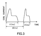
- the dosing valve 104 is energized to inject urea solution for a period of t 1 at (fixed) intervals of to.
- the length of t 1 varies with the amount of injected urea solution.
- the energization is maintained for a predetermined time.
- the predetermined time is a length of time required to return the urea solution in the piping to the urea tank 105.
- the SCR system 100 is provided with a recovery control system that allows urea solution in the dosing valve 104 that is heated by the exhaust gas at high temperature and crystallizes and fixates to the interior of the dosing valve 104 to recover from a malfunction to a normal state.
- the recovery control system is provided in the DCU 126 and comprises abnormality detection means of detecting an abnormality of the dosing valve 104 and recovery control means.
- the abnormality detection means is configured to detect an abnormality based on whether or not the open/close operation of the dosing valve 104 is normal.
- the recovery control means is configured to control the supply module 106 to feed the urea solution in the dosing valve 104 back to the urea tank 105 when the abnormality detection means detects an abnormality of the dosing valve 104. More specifically, the recovery control means is configured to open the dosing valve 104, switch the reverting valve 115 of the supply module 106, activate the SM pump 112 of the supply module 106 and forcedly perform emptying (forced emptying).
- the recovery control system is configured to repeatedly perform the following operation.
- the abnormality detection means detects whether or not the dosing valve 104 is normal (S401).
- the recovery control means opens the dosing valve 104, switches the reverting valve 115 of the supply module 106, activates the SM pump 112 of the supply module 106 and perform forced emptying (S402).
- urea crystals can be removed along with the urea solution by the force of feeding the urea solution in the dosing valve 104 back to the urea tank 105. If urea crystals cannot be removed (and thus the dosing valve 104 does not move and is kept closed), the urea solution cannot be fed back nor supplied and therefore remains in the dosing valve 104. However, if the forced emptying and the supply of urea solution are still repeated to change the pressure applied to the urea solution in the dosing valve 104, the urea solution can be fed to the site of the urea crystal, and the urea crystal can be resolved and removed.
- the malfunction of the dosing valve 104 can be eliminated. If the malfunction of the dosing valve 104 cannot be eliminated by repeating the Steps S401 to S404 to repeat the forced emptying and the supply of urea solution a predetermined number of times, it can be determined that the dosing valve 104 has failed. In this case, it can be determined whether recovery from the malfunction is possible or not, so that it is possible to avoid warning the driver or the like of a failure when recovery from the malfunction is possible.
- the recovery control system can allow the dosing valve to recover from a malfunction to a normal state.
- the dosing valve 104 In emptying, as described above, the dosing valve 104 is opened in advance, and the exhaust gas (air) in the exhaust pipe 102 is sucked into the urea tank 105 from the dosing valve 104. That is, if emptying occurs, the exhaust gas is sucked through the liquid feed line 116, the pressure-feed line 117 and other lines. Therefore, foreign matters or the like in the liquid feed line 116 and the pressure-feed line 117 can also be removed.
- the recovery control system may be provided with pressure abnormality detection means that detects an abnormality in the urea solution pressure based on the measurement value of the urea solution pressure sensor 114 that measures the pressure of the urea solution supplied to the dosing valve 104, the recovery control means may perform forced emptying when the pressure abnormality detection means detects an abnormality in the pressure of the urea solution.
- the pressure abnormality detection means may detect whether the pressure of the urea solution supplied to the dosing valve 104 is abnormal or not (becomes constant or not) (S501), and the recovery control means may perform forced emptying (S502) when a pressure abnormality is detected in S501.
- the reverting valve 115 may not be activated, and the SM pump 112 may simply be turned off.
Landscapes
- Engineering & Computer Science (AREA)
- Chemical & Material Sciences (AREA)
- Chemical Kinetics & Catalysis (AREA)
- Combustion & Propulsion (AREA)
- Mechanical Engineering (AREA)
- General Engineering & Computer Science (AREA)
- Health & Medical Sciences (AREA)
- Toxicology (AREA)
- Exhaust Gas After Treatment (AREA)
- Exhaust Gas Treatment By Means Of Catalyst (AREA)
Applications Claiming Priority (2)
| Application Number | Priority Date | Filing Date | Title |
|---|---|---|---|
| JP2010119714A JP5633190B2 (ja) | 2010-05-25 | 2010-05-25 | 復帰制御システム |
| PCT/JP2011/061213 WO2011148810A1 (ja) | 2010-05-25 | 2011-05-16 | 復帰制御システム |
Publications (3)
| Publication Number | Publication Date |
|---|---|
| EP2578834A1 true EP2578834A1 (de) | 2013-04-10 |
| EP2578834A4 EP2578834A4 (de) | 2017-03-01 |
| EP2578834B1 EP2578834B1 (de) | 2018-10-17 |
Family
ID=45003801
Family Applications (1)
| Application Number | Title | Priority Date | Filing Date |
|---|---|---|---|
| EP11786509.7A Not-in-force EP2578834B1 (de) | 2010-05-25 | 2011-05-16 | Wiederherstellungssteuerungssystem |
Country Status (5)
| Country | Link |
|---|---|
| US (1) | US9127584B2 (de) |
| EP (1) | EP2578834B1 (de) |
| JP (1) | JP5633190B2 (de) |
| CN (1) | CN102985652B (de) |
| WO (1) | WO2011148810A1 (de) |
Cited By (3)
| Publication number | Priority date | Publication date | Assignee | Title |
|---|---|---|---|---|
| WO2015011532A1 (en) * | 2013-07-26 | 2015-01-29 | Toyota Jidosha Kabushiki Kaisha | Scr exhaust emission control system and method therefore, for filling the urea reducing agent after returning to the tank |
| EP2787185A4 (de) * | 2011-11-29 | 2015-10-14 | Hino Motors Ltd | Verfahren zur steuerung eines injektors |
| EP3333387A1 (de) * | 2016-12-12 | 2018-06-13 | Perkins Engines Company Limited | Erkennung von injektorablagerungen für scr-einspritzsystem |
Families Citing this family (14)
| Publication number | Priority date | Publication date | Assignee | Title |
|---|---|---|---|---|
| JP5546511B2 (ja) * | 2010-09-13 | 2014-07-09 | ボッシュ株式会社 | 還元剤噴射装置及びその制御方法 |
| US9145817B2 (en) * | 2010-11-08 | 2015-09-29 | Bosch Corporation | Reducing agent injection valve abnormality detection unit and reducing agent supply apparatus |
| JP5653208B2 (ja) * | 2010-12-27 | 2015-01-14 | ボッシュ株式会社 | 還元剤供給装置およびその制御方法 |
| JP6024478B2 (ja) * | 2013-01-28 | 2016-11-16 | いすゞ自動車株式会社 | 尿素scr用尿素水配管閉塞検出装置 |
| DE112013000161C5 (de) * | 2013-03-15 | 2023-03-16 | Komatsu Ltd. | Abgasnachbehandlungseinheit und ein diese enthaltendes Baufahrzeug |
| KR101438630B1 (ko) * | 2013-04-15 | 2014-09-05 | 현대자동차 주식회사 | 선택적 촉매 환원(scr) 시스템의 우레아 분사 노즐의 막힘 방지 방법 |
| DE102013105710B4 (de) * | 2013-06-04 | 2025-05-28 | Schaeffler Technologies AG & Co. KG | Verfahren zum Betrieb einer Vorrichtung zur Förderung einer Flüssigkeit |
| JP6540523B2 (ja) * | 2016-01-22 | 2019-07-10 | 株式会社デンソー | 異常判定装置 |
| WO2017187640A1 (ja) * | 2016-04-28 | 2017-11-02 | 株式会社小松製作所 | 排気ガス後処理ユニット及び作業車両 |
| DE102016215380A1 (de) * | 2016-08-17 | 2018-02-22 | Robert Bosch Gmbh | Verfahren zur Erkennung einer blockierten Druckleitung |
| US10378415B2 (en) * | 2017-08-30 | 2019-08-13 | Caterpillar Inc. | Diagnostic and mitigation strategy for reductant injector obstruction in exhaust system |
| JP2019052573A (ja) * | 2017-09-14 | 2019-04-04 | 日野自動車株式会社 | 尿素噴射システムの制御方法 |
| US11268417B2 (en) | 2019-06-26 | 2022-03-08 | Cummins Emission Solutions Inc. | Liquid only lance injector |
| CN113606017A (zh) * | 2021-06-30 | 2021-11-05 | 徐工集团工程机械股份有限公司科技分公司 | 一种装载机及其延时断电控制装置和控制方法 |
Family Cites Families (14)
| Publication number | Priority date | Publication date | Assignee | Title |
|---|---|---|---|---|
| DE19512339B4 (de) * | 1995-04-01 | 2010-06-10 | Robert Bosch Gmbh | Elektromagnetisch betätigbares Brennstoffeinspritzventil |
| JP2000303826A (ja) | 1999-04-16 | 2000-10-31 | Isuzu Motors Ltd | ディーゼルエンジンの排ガス浄化装置 |
| JP4326976B2 (ja) * | 2003-10-22 | 2009-09-09 | 日産ディーゼル工業株式会社 | エンジンの排気浄化装置 |
| FR2879239A1 (fr) * | 2004-12-15 | 2006-06-16 | Inergy Automotive Systems Res | Systeme de stockage et d'injection d'un additif dans des gaz d'echappement d'un moteur |
| JP2006250117A (ja) * | 2005-03-14 | 2006-09-21 | Nissan Diesel Motor Co Ltd | 排気浄化システムの還元剤噴射状況判定装置 |
| JP4509871B2 (ja) * | 2005-06-09 | 2010-07-21 | 三菱ふそうトラック・バス株式会社 | 排気浄化装置 |
| JP4444165B2 (ja) * | 2005-06-10 | 2010-03-31 | 日産ディーゼル工業株式会社 | エンジンの排気浄化装置 |
| JP4673145B2 (ja) * | 2005-06-24 | 2011-04-20 | 株式会社サムソン | 尿素水噴射ノズルの詰まりを自動解消する脱硝装置 |
| JP2008151094A (ja) * | 2006-12-20 | 2008-07-03 | Aisan Ind Co Ltd | 内燃機関の排気浄化装置 |
| JP4165896B2 (ja) * | 2007-02-19 | 2008-10-15 | ボッシュ株式会社 | 還元剤経路の詰まり判定装置及び還元剤経路の詰まり判定方法 |
| JP2009264191A (ja) * | 2008-04-23 | 2009-11-12 | Samson Co Ltd | 脱硝装置 |
| WO2010029792A1 (ja) * | 2008-09-12 | 2010-03-18 | ボッシュ株式会社 | 内燃機関の排気浄化装置及びその制御方法 |
| DE102008043469B4 (de) * | 2008-11-04 | 2019-01-17 | Robert Bosch Gmbh | Verfahren zur Prüfung der Funktionsfähigkeit eines Dosierventils eines NOx-Reduktionssystems einer Brennkraftmaschine |
| JP5325850B2 (ja) * | 2009-10-30 | 2013-10-23 | ボッシュ株式会社 | 還元剤噴射弁の異常検出装置及び異常検出方法、並びに内燃機関の排気浄化装置 |
-
2010
- 2010-05-25 JP JP2010119714A patent/JP5633190B2/ja not_active Expired - Fee Related
-
2011
- 2011-05-16 US US13/699,524 patent/US9127584B2/en active Active
- 2011-05-16 CN CN201180025593.1A patent/CN102985652B/zh active Active
- 2011-05-16 WO PCT/JP2011/061213 patent/WO2011148810A1/ja not_active Ceased
- 2011-05-16 EP EP11786509.7A patent/EP2578834B1/de not_active Not-in-force
Non-Patent Citations (1)
| Title |
|---|
| See references of WO2011148810A1 * |
Cited By (4)
| Publication number | Priority date | Publication date | Assignee | Title |
|---|---|---|---|---|
| EP2787185A4 (de) * | 2011-11-29 | 2015-10-14 | Hino Motors Ltd | Verfahren zur steuerung eines injektors |
| WO2015011532A1 (en) * | 2013-07-26 | 2015-01-29 | Toyota Jidosha Kabushiki Kaisha | Scr exhaust emission control system and method therefore, for filling the urea reducing agent after returning to the tank |
| EP3333387A1 (de) * | 2016-12-12 | 2018-06-13 | Perkins Engines Company Limited | Erkennung von injektorablagerungen für scr-einspritzsystem |
| US10337385B2 (en) | 2016-12-12 | 2019-07-02 | Perkins Engines Company Limited | Injector deposit detection for SCR injection system |
Also Published As
| Publication number | Publication date |
|---|---|
| JP5633190B2 (ja) | 2014-12-03 |
| CN102985652B (zh) | 2015-03-25 |
| CN102985652A (zh) | 2013-03-20 |
| JP2011247136A (ja) | 2011-12-08 |
| US9127584B2 (en) | 2015-09-08 |
| EP2578834B1 (de) | 2018-10-17 |
| US20130186073A1 (en) | 2013-07-25 |
| EP2578834A4 (de) | 2017-03-01 |
| WO2011148810A1 (ja) | 2011-12-01 |
Similar Documents
| Publication | Publication Date | Title |
|---|---|---|
| EP2578834B1 (de) | Wiederherstellungssteuerungssystem | |
| EP2578831A1 (de) | Vorrichtung für selektive katalytische reduktion | |
| EP2599972B1 (de) | Diagnosevorrichtung für einen nox-sensor und scr-system | |
| EP2573341B1 (de) | Scr-schmelzsteuerungssystem | |
| JP5625475B2 (ja) | 排ガス浄化システム | |
| EP2573345A1 (de) | Scr-system | |
| JP5906637B2 (ja) | 異物除去方法及び選択還元触媒システム | |
| CN102892989B (zh) | 尿素水温度传感器的有效性诊断系统 | |
| EP2573343B1 (de) | Diagnosesystem für einen temperatursensor für eine harnstofflösung | |
| JP2011241722A (ja) | 排ガス浄化システム |
Legal Events
| Date | Code | Title | Description |
|---|---|---|---|
| PUAI | Public reference made under article 153(3) epc to a published international application that has entered the european phase |
Free format text: ORIGINAL CODE: 0009012 |
|
| 17P | Request for examination filed |
Effective date: 20121218 |
|
| AK | Designated contracting states |
Kind code of ref document: A1 Designated state(s): AL AT BE BG CH CY CZ DE DK EE ES FI FR GB GR HR HU IE IS IT LI LT LU LV MC MK MT NL NO PL PT RO RS SE SI SK SM TR |
|
| DAX | Request for extension of the european patent (deleted) | ||
| RA4 | Supplementary search report drawn up and despatched (corrected) |
Effective date: 20170131 |
|
| RIC1 | Information provided on ipc code assigned before grant |
Ipc: F01N 3/18 20060101AFI20170125BHEP Ipc: F01N 3/20 20060101ALI20170125BHEP Ipc: F01N 3/08 20060101ALI20170125BHEP Ipc: B01D 53/94 20060101ALI20170125BHEP |
|
| RIC1 | Information provided on ipc code assigned before grant |
Ipc: B01D 53/94 20060101ALI20180305BHEP Ipc: F01N 3/20 20060101ALI20180305BHEP Ipc: F01N 3/08 20060101ALI20180305BHEP Ipc: F01N 3/18 20060101AFI20180305BHEP |
|
| GRAP | Despatch of communication of intention to grant a patent |
Free format text: ORIGINAL CODE: EPIDOSNIGR1 |
|
| STAA | Information on the status of an ep patent application or granted ep patent |
Free format text: STATUS: GRANT OF PATENT IS INTENDED |
|
| INTG | Intention to grant announced |
Effective date: 20180430 |
|
| GRAS | Grant fee paid |
Free format text: ORIGINAL CODE: EPIDOSNIGR3 |
|
| GRAA | (expected) grant |
Free format text: ORIGINAL CODE: 0009210 |
|
| STAA | Information on the status of an ep patent application or granted ep patent |
Free format text: STATUS: THE PATENT HAS BEEN GRANTED |
|
| AK | Designated contracting states |
Kind code of ref document: B1 Designated state(s): AL AT BE BG CH CY CZ DE DK EE ES FI FR GB GR HR HU IE IS IT LI LT LU LV MC MK MT NL NO PL PT RO RS SE SI SK SM TR |
|
| REG | Reference to a national code |
Ref country code: GB Ref legal event code: FG4D |
|
| REG | Reference to a national code |
Ref country code: CH Ref legal event code: EP |
|
| REG | Reference to a national code |
Ref country code: IE Ref legal event code: FG4D |
|
| REG | Reference to a national code |
Ref country code: DE Ref legal event code: R096 Ref document number: 602011053013 Country of ref document: DE Ref country code: AT Ref legal event code: REF Ref document number: 1054294 Country of ref document: AT Kind code of ref document: T Effective date: 20181115 |
|
| REG | Reference to a national code |
Ref country code: NL Ref legal event code: MP Effective date: 20181017 |
|
| REG | Reference to a national code |
Ref country code: LT Ref legal event code: MG4D |
|
| REG | Reference to a national code |
Ref country code: AT Ref legal event code: MK05 Ref document number: 1054294 Country of ref document: AT Kind code of ref document: T Effective date: 20181017 |
|
| PG25 | Lapsed in a contracting state [announced via postgrant information from national office to epo] |
Ref country code: NL Free format text: LAPSE BECAUSE OF FAILURE TO SUBMIT A TRANSLATION OF THE DESCRIPTION OR TO PAY THE FEE WITHIN THE PRESCRIBED TIME-LIMIT Effective date: 20181017 |
|
| PG25 | Lapsed in a contracting state [announced via postgrant information from national office to epo] |
Ref country code: HR Free format text: LAPSE BECAUSE OF FAILURE TO SUBMIT A TRANSLATION OF THE DESCRIPTION OR TO PAY THE FEE WITHIN THE PRESCRIBED TIME-LIMIT Effective date: 20181017 Ref country code: AT Free format text: LAPSE BECAUSE OF FAILURE TO SUBMIT A TRANSLATION OF THE DESCRIPTION OR TO PAY THE FEE WITHIN THE PRESCRIBED TIME-LIMIT Effective date: 20181017 Ref country code: PL Free format text: LAPSE BECAUSE OF FAILURE TO SUBMIT A TRANSLATION OF THE DESCRIPTION OR TO PAY THE FEE WITHIN THE PRESCRIBED TIME-LIMIT Effective date: 20181017 Ref country code: LT Free format text: LAPSE BECAUSE OF FAILURE TO SUBMIT A TRANSLATION OF THE DESCRIPTION OR TO PAY THE FEE WITHIN THE PRESCRIBED TIME-LIMIT Effective date: 20181017 Ref country code: ES Free format text: LAPSE BECAUSE OF FAILURE TO SUBMIT A TRANSLATION OF THE DESCRIPTION OR TO PAY THE FEE WITHIN THE PRESCRIBED TIME-LIMIT Effective date: 20181017 Ref country code: FI Free format text: LAPSE BECAUSE OF FAILURE TO SUBMIT A TRANSLATION OF THE DESCRIPTION OR TO PAY THE FEE WITHIN THE PRESCRIBED TIME-LIMIT Effective date: 20181017 Ref country code: BG Free format text: LAPSE BECAUSE OF FAILURE TO SUBMIT A TRANSLATION OF THE DESCRIPTION OR TO PAY THE FEE WITHIN THE PRESCRIBED TIME-LIMIT Effective date: 20190117 Ref country code: LV Free format text: LAPSE BECAUSE OF FAILURE TO SUBMIT A TRANSLATION OF THE DESCRIPTION OR TO PAY THE FEE WITHIN THE PRESCRIBED TIME-LIMIT Effective date: 20181017 Ref country code: IS Free format text: LAPSE BECAUSE OF FAILURE TO SUBMIT A TRANSLATION OF THE DESCRIPTION OR TO PAY THE FEE WITHIN THE PRESCRIBED TIME-LIMIT Effective date: 20190217 Ref country code: NO Free format text: LAPSE BECAUSE OF FAILURE TO SUBMIT A TRANSLATION OF THE DESCRIPTION OR TO PAY THE FEE WITHIN THE PRESCRIBED TIME-LIMIT Effective date: 20190117 |
|
| PG25 | Lapsed in a contracting state [announced via postgrant information from national office to epo] |
Ref country code: RS Free format text: LAPSE BECAUSE OF FAILURE TO SUBMIT A TRANSLATION OF THE DESCRIPTION OR TO PAY THE FEE WITHIN THE PRESCRIBED TIME-LIMIT Effective date: 20181017 Ref country code: GR Free format text: LAPSE BECAUSE OF FAILURE TO SUBMIT A TRANSLATION OF THE DESCRIPTION OR TO PAY THE FEE WITHIN THE PRESCRIBED TIME-LIMIT Effective date: 20190118 Ref country code: AL Free format text: LAPSE BECAUSE OF FAILURE TO SUBMIT A TRANSLATION OF THE DESCRIPTION OR TO PAY THE FEE WITHIN THE PRESCRIBED TIME-LIMIT Effective date: 20181017 Ref country code: PT Free format text: LAPSE BECAUSE OF FAILURE TO SUBMIT A TRANSLATION OF THE DESCRIPTION OR TO PAY THE FEE WITHIN THE PRESCRIBED TIME-LIMIT Effective date: 20190217 Ref country code: SE Free format text: LAPSE BECAUSE OF FAILURE TO SUBMIT A TRANSLATION OF THE DESCRIPTION OR TO PAY THE FEE WITHIN THE PRESCRIBED TIME-LIMIT Effective date: 20181017 |
|
| REG | Reference to a national code |
Ref country code: DE Ref legal event code: R097 Ref document number: 602011053013 Country of ref document: DE |
|
| PG25 | Lapsed in a contracting state [announced via postgrant information from national office to epo] |
Ref country code: DK Free format text: LAPSE BECAUSE OF FAILURE TO SUBMIT A TRANSLATION OF THE DESCRIPTION OR TO PAY THE FEE WITHIN THE PRESCRIBED TIME-LIMIT Effective date: 20181017 Ref country code: IT Free format text: LAPSE BECAUSE OF FAILURE TO SUBMIT A TRANSLATION OF THE DESCRIPTION OR TO PAY THE FEE WITHIN THE PRESCRIBED TIME-LIMIT Effective date: 20181017 Ref country code: CZ Free format text: LAPSE BECAUSE OF FAILURE TO SUBMIT A TRANSLATION OF THE DESCRIPTION OR TO PAY THE FEE WITHIN THE PRESCRIBED TIME-LIMIT Effective date: 20181017 |
|
| PGFP | Annual fee paid to national office [announced via postgrant information from national office to epo] |
Ref country code: DE Payment date: 20190619 Year of fee payment: 9 |
|
| PLBE | No opposition filed within time limit |
Free format text: ORIGINAL CODE: 0009261 |
|
| STAA | Information on the status of an ep patent application or granted ep patent |
Free format text: STATUS: NO OPPOSITION FILED WITHIN TIME LIMIT |
|
| PG25 | Lapsed in a contracting state [announced via postgrant information from national office to epo] |
Ref country code: SK Free format text: LAPSE BECAUSE OF FAILURE TO SUBMIT A TRANSLATION OF THE DESCRIPTION OR TO PAY THE FEE WITHIN THE PRESCRIBED TIME-LIMIT Effective date: 20181017 Ref country code: EE Free format text: LAPSE BECAUSE OF FAILURE TO SUBMIT A TRANSLATION OF THE DESCRIPTION OR TO PAY THE FEE WITHIN THE PRESCRIBED TIME-LIMIT Effective date: 20181017 Ref country code: SM Free format text: LAPSE BECAUSE OF FAILURE TO SUBMIT A TRANSLATION OF THE DESCRIPTION OR TO PAY THE FEE WITHIN THE PRESCRIBED TIME-LIMIT Effective date: 20181017 Ref country code: RO Free format text: LAPSE BECAUSE OF FAILURE TO SUBMIT A TRANSLATION OF THE DESCRIPTION OR TO PAY THE FEE WITHIN THE PRESCRIBED TIME-LIMIT Effective date: 20181017 |
|
| PGFP | Annual fee paid to national office [announced via postgrant information from national office to epo] |
Ref country code: FR Payment date: 20190521 Year of fee payment: 9 |
|
| 26N | No opposition filed |
Effective date: 20190718 |
|
| PG25 | Lapsed in a contracting state [announced via postgrant information from national office to epo] |
Ref country code: SI Free format text: LAPSE BECAUSE OF FAILURE TO SUBMIT A TRANSLATION OF THE DESCRIPTION OR TO PAY THE FEE WITHIN THE PRESCRIBED TIME-LIMIT Effective date: 20181017 |
|
| PGFP | Annual fee paid to national office [announced via postgrant information from national office to epo] |
Ref country code: GB Payment date: 20190523 Year of fee payment: 9 |
|
| REG | Reference to a national code |
Ref country code: CH Ref legal event code: PL |
|
| PG25 | Lapsed in a contracting state [announced via postgrant information from national office to epo] |
Ref country code: MC Free format text: LAPSE BECAUSE OF FAILURE TO SUBMIT A TRANSLATION OF THE DESCRIPTION OR TO PAY THE FEE WITHIN THE PRESCRIBED TIME-LIMIT Effective date: 20181017 Ref country code: LI Free format text: LAPSE BECAUSE OF NON-PAYMENT OF DUE FEES Effective date: 20190531 Ref country code: CH Free format text: LAPSE BECAUSE OF NON-PAYMENT OF DUE FEES Effective date: 20190531 |
|
| REG | Reference to a national code |
Ref country code: BE Ref legal event code: MM Effective date: 20190531 |
|
| PG25 | Lapsed in a contracting state [announced via postgrant information from national office to epo] |
Ref country code: LU Free format text: LAPSE BECAUSE OF NON-PAYMENT OF DUE FEES Effective date: 20190516 |
|
| PG25 | Lapsed in a contracting state [announced via postgrant information from national office to epo] |
Ref country code: TR Free format text: LAPSE BECAUSE OF FAILURE TO SUBMIT A TRANSLATION OF THE DESCRIPTION OR TO PAY THE FEE WITHIN THE PRESCRIBED TIME-LIMIT Effective date: 20181017 |
|
| PG25 | Lapsed in a contracting state [announced via postgrant information from national office to epo] |
Ref country code: IE Free format text: LAPSE BECAUSE OF NON-PAYMENT OF DUE FEES Effective date: 20190516 |
|
| PG25 | Lapsed in a contracting state [announced via postgrant information from national office to epo] |
Ref country code: BE Free format text: LAPSE BECAUSE OF NON-PAYMENT OF DUE FEES Effective date: 20190531 |
|
| REG | Reference to a national code |
Ref country code: DE Ref legal event code: R119 Ref document number: 602011053013 Country of ref document: DE |
|
| GBPC | Gb: european patent ceased through non-payment of renewal fee |
Effective date: 20200516 |
|
| PG25 | Lapsed in a contracting state [announced via postgrant information from national office to epo] |
Ref country code: FR Free format text: LAPSE BECAUSE OF NON-PAYMENT OF DUE FEES Effective date: 20200531 Ref country code: GB Free format text: LAPSE BECAUSE OF NON-PAYMENT OF DUE FEES Effective date: 20200516 |
|
| PG25 | Lapsed in a contracting state [announced via postgrant information from national office to epo] |
Ref country code: DE Free format text: LAPSE BECAUSE OF NON-PAYMENT OF DUE FEES Effective date: 20201201 Ref country code: CY Free format text: LAPSE BECAUSE OF FAILURE TO SUBMIT A TRANSLATION OF THE DESCRIPTION OR TO PAY THE FEE WITHIN THE PRESCRIBED TIME-LIMIT Effective date: 20181017 |
|
| PG25 | Lapsed in a contracting state [announced via postgrant information from national office to epo] |
Ref country code: HU Free format text: LAPSE BECAUSE OF FAILURE TO SUBMIT A TRANSLATION OF THE DESCRIPTION OR TO PAY THE FEE WITHIN THE PRESCRIBED TIME-LIMIT; INVALID AB INITIO Effective date: 20110516 Ref country code: MT Free format text: LAPSE BECAUSE OF FAILURE TO SUBMIT A TRANSLATION OF THE DESCRIPTION OR TO PAY THE FEE WITHIN THE PRESCRIBED TIME-LIMIT Effective date: 20181017 |
|
| PG25 | Lapsed in a contracting state [announced via postgrant information from national office to epo] |
Ref country code: MK Free format text: LAPSE BECAUSE OF FAILURE TO SUBMIT A TRANSLATION OF THE DESCRIPTION OR TO PAY THE FEE WITHIN THE PRESCRIBED TIME-LIMIT Effective date: 20181017 |