EP2578855A1 - Système d'épuration des gaz d'échappement - Google Patents
Système d'épuration des gaz d'échappement Download PDFInfo
- Publication number
- EP2578855A1 EP2578855A1 EP11786515.4A EP11786515A EP2578855A1 EP 2578855 A1 EP2578855 A1 EP 2578855A1 EP 11786515 A EP11786515 A EP 11786515A EP 2578855 A1 EP2578855 A1 EP 2578855A1
- Authority
- EP
- European Patent Office
- Prior art keywords
- exhaust gas
- exhaust
- post injection
- temperature
- dpd
- Prior art date
- Legal status (The legal status is an assumption and is not a legal conclusion. Google has not performed a legal analysis and makes no representation as to the accuracy of the status listed.)
- Granted
Links
Images


Classifications
-
- F—MECHANICAL ENGINEERING; LIGHTING; HEATING; WEAPONS; BLASTING
- F02—COMBUSTION ENGINES; HOT-GAS OR COMBUSTION-PRODUCT ENGINE PLANTS
- F02D—CONTROLLING COMBUSTION ENGINES
- F02D41/00—Electrical control of supply of combustible mixture or its constituents
- F02D41/02—Circuit arrangements for generating control signals
- F02D41/021—Introducing corrections for particular conditions exterior to the engine
- F02D41/0235—Introducing corrections for particular conditions exterior to the engine in relation with the state of the exhaust gas treating apparatus
- F02D41/027—Introducing corrections for particular conditions exterior to the engine in relation with the state of the exhaust gas treating apparatus to purge or regenerate the exhaust gas treating apparatus
- F02D41/029—Introducing corrections for particular conditions exterior to the engine in relation with the state of the exhaust gas treating apparatus to purge or regenerate the exhaust gas treating apparatus the exhaust gas treating apparatus being a particulate filter
-
- F—MECHANICAL ENGINEERING; LIGHTING; HEATING; WEAPONS; BLASTING
- F01—MACHINES OR ENGINES IN GENERAL; ENGINE PLANTS IN GENERAL; STEAM ENGINES
- F01N—GAS-FLOW SILENCERS OR EXHAUST APPARATUS FOR MACHINES OR ENGINES IN GENERAL; GAS-FLOW SILENCERS OR EXHAUST APPARATUS FOR INTERNAL-COMBUSTION ENGINES
- F01N3/00—Exhaust or silencing apparatus having means for purifying, rendering innocuous, or otherwise treating exhaust
- F01N3/02—Exhaust or silencing apparatus having means for purifying, rendering innocuous, or otherwise treating exhaust for cooling, or for removing solid constituents of, exhaust
- F01N3/021—Exhaust or silencing apparatus having means for purifying, rendering innocuous, or otherwise treating exhaust for cooling, or for removing solid constituents of, exhaust by means of filters
- F01N3/033—Exhaust or silencing apparatus having means for purifying, rendering innocuous, or otherwise treating exhaust for cooling, or for removing solid constituents of, exhaust by means of filters in combination with other devices
- F01N3/035—Exhaust or silencing apparatus having means for purifying, rendering innocuous, or otherwise treating exhaust for cooling, or for removing solid constituents of, exhaust by means of filters in combination with other devices with catalytic reactors
-
- F—MECHANICAL ENGINEERING; LIGHTING; HEATING; WEAPONS; BLASTING
- F02—COMBUSTION ENGINES; HOT-GAS OR COMBUSTION-PRODUCT ENGINE PLANTS
- F02D—CONTROLLING COMBUSTION ENGINES
- F02D41/00—Electrical control of supply of combustible mixture or its constituents
- F02D41/02—Circuit arrangements for generating control signals
- F02D41/021—Introducing corrections for particular conditions exterior to the engine
- F02D41/0235—Introducing corrections for particular conditions exterior to the engine in relation with the state of the exhaust gas treating apparatus
- F02D41/024—Introducing corrections for particular conditions exterior to the engine in relation with the state of the exhaust gas treating apparatus to increase temperature of the exhaust gas treating apparatus
-
- F—MECHANICAL ENGINEERING; LIGHTING; HEATING; WEAPONS; BLASTING
- F02—COMBUSTION ENGINES; HOT-GAS OR COMBUSTION-PRODUCT ENGINE PLANTS
- F02D—CONTROLLING COMBUSTION ENGINES
- F02D41/00—Electrical control of supply of combustible mixture or its constituents
- F02D41/02—Circuit arrangements for generating control signals
- F02D41/021—Introducing corrections for particular conditions exterior to the engine
- F02D41/0235—Introducing corrections for particular conditions exterior to the engine in relation with the state of the exhaust gas treating apparatus
- F02D41/024—Introducing corrections for particular conditions exterior to the engine in relation with the state of the exhaust gas treating apparatus to increase temperature of the exhaust gas treating apparatus
- F02D41/025—Introducing corrections for particular conditions exterior to the engine in relation with the state of the exhaust gas treating apparatus to increase temperature of the exhaust gas treating apparatus by changing the composition of the exhaust gas, e.g. for exothermic reaction on exhaust gas treating apparatus
-
- F—MECHANICAL ENGINEERING; LIGHTING; HEATING; WEAPONS; BLASTING
- F02—COMBUSTION ENGINES; HOT-GAS OR COMBUSTION-PRODUCT ENGINE PLANTS
- F02D—CONTROLLING COMBUSTION ENGINES
- F02D41/00—Electrical control of supply of combustible mixture or its constituents
- F02D41/02—Circuit arrangements for generating control signals
- F02D41/04—Introducing corrections for particular operating conditions
- F02D41/10—Introducing corrections for particular operating conditions for acceleration
- F02D41/107—Introducing corrections for particular operating conditions for acceleration and deceleration
-
- F—MECHANICAL ENGINEERING; LIGHTING; HEATING; WEAPONS; BLASTING
- F02—COMBUSTION ENGINES; HOT-GAS OR COMBUSTION-PRODUCT ENGINE PLANTS
- F02D—CONTROLLING COMBUSTION ENGINES
- F02D41/00—Electrical control of supply of combustible mixture or its constituents
- F02D41/02—Circuit arrangements for generating control signals
- F02D41/14—Introducing closed-loop corrections
- F02D41/1401—Introducing closed-loop corrections characterised by the control or regulation method
-
- F—MECHANICAL ENGINEERING; LIGHTING; HEATING; WEAPONS; BLASTING
- F02—COMBUSTION ENGINES; HOT-GAS OR COMBUSTION-PRODUCT ENGINE PLANTS
- F02D—CONTROLLING COMBUSTION ENGINES
- F02D41/00—Electrical control of supply of combustible mixture or its constituents
- F02D41/02—Circuit arrangements for generating control signals
- F02D41/14—Introducing closed-loop corrections
- F02D41/1438—Introducing closed-loop corrections using means for determining characteristics of the combustion gases; Sensors therefor
- F02D41/1444—Introducing closed-loop corrections using means for determining characteristics of the combustion gases; Sensors therefor characterised by the characteristics of the combustion gases
- F02D41/1446—Introducing closed-loop corrections using means for determining characteristics of the combustion gases; Sensors therefor characterised by the characteristics of the combustion gases the characteristics being exhaust temperatures
-
- F—MECHANICAL ENGINEERING; LIGHTING; HEATING; WEAPONS; BLASTING
- F02—COMBUSTION ENGINES; HOT-GAS OR COMBUSTION-PRODUCT ENGINE PLANTS
- F02D—CONTROLLING COMBUSTION ENGINES
- F02D41/00—Electrical control of supply of combustible mixture or its constituents
- F02D41/02—Circuit arrangements for generating control signals
- F02D41/14—Introducing closed-loop corrections
- F02D41/1438—Introducing closed-loop corrections using means for determining characteristics of the combustion gases; Sensors therefor
- F02D41/1477—Introducing closed-loop corrections using means for determining characteristics of the combustion gases; Sensors therefor characterised by the regulation circuit or part of it,(e.g. comparator, PI regulator, output)
- F02D41/1482—Integrator, i.e. variable slope
-
- F—MECHANICAL ENGINEERING; LIGHTING; HEATING; WEAPONS; BLASTING
- F02—COMBUSTION ENGINES; HOT-GAS OR COMBUSTION-PRODUCT ENGINE PLANTS
- F02D—CONTROLLING COMBUSTION ENGINES
- F02D41/00—Electrical control of supply of combustible mixture or its constituents
- F02D41/02—Circuit arrangements for generating control signals
- F02D41/14—Introducing closed-loop corrections
- F02D41/1438—Introducing closed-loop corrections using means for determining characteristics of the combustion gases; Sensors therefor
- F02D41/1486—Introducing closed-loop corrections using means for determining characteristics of the combustion gases; Sensors therefor with correction for particular operating conditions
- F02D41/1488—Inhibiting the regulation
-
- F—MECHANICAL ENGINEERING; LIGHTING; HEATING; WEAPONS; BLASTING
- F02—COMBUSTION ENGINES; HOT-GAS OR COMBUSTION-PRODUCT ENGINE PLANTS
- F02D—CONTROLLING COMBUSTION ENGINES
- F02D41/00—Electrical control of supply of combustible mixture or its constituents
- F02D41/30—Controlling fuel injection
- F02D41/38—Controlling fuel injection of the high pressure type
- F02D41/40—Controlling fuel injection of the high pressure type with means for controlling injection timing or duration
- F02D41/402—Multiple injections
- F02D41/405—Multiple injections with post injections
-
- F—MECHANICAL ENGINEERING; LIGHTING; HEATING; WEAPONS; BLASTING
- F02—COMBUSTION ENGINES; HOT-GAS OR COMBUSTION-PRODUCT ENGINE PLANTS
- F02D—CONTROLLING COMBUSTION ENGINES
- F02D9/00—Controlling engines by throttling air or fuel-and-air induction conduits or exhaust conduits
- F02D9/04—Controlling engines by throttling air or fuel-and-air induction conduits or exhaust conduits concerning exhaust conduits
- F02D9/06—Exhaust brakes
-
- F—MECHANICAL ENGINEERING; LIGHTING; HEATING; WEAPONS; BLASTING
- F01—MACHINES OR ENGINES IN GENERAL; ENGINE PLANTS IN GENERAL; STEAM ENGINES
- F01N—GAS-FLOW SILENCERS OR EXHAUST APPARATUS FOR MACHINES OR ENGINES IN GENERAL; GAS-FLOW SILENCERS OR EXHAUST APPARATUS FOR INTERNAL-COMBUSTION ENGINES
- F01N3/00—Exhaust or silencing apparatus having means for purifying, rendering innocuous, or otherwise treating exhaust
- F01N3/02—Exhaust or silencing apparatus having means for purifying, rendering innocuous, or otherwise treating exhaust for cooling, or for removing solid constituents of, exhaust
- F01N3/021—Exhaust or silencing apparatus having means for purifying, rendering innocuous, or otherwise treating exhaust for cooling, or for removing solid constituents of, exhaust by means of filters
- F01N3/023—Exhaust or silencing apparatus having means for purifying, rendering innocuous, or otherwise treating exhaust for cooling, or for removing solid constituents of, exhaust by means of filters using means for regenerating the filters, e.g. by burning trapped particles
- F01N3/0235—Exhaust or silencing apparatus having means for purifying, rendering innocuous, or otherwise treating exhaust for cooling, or for removing solid constituents of, exhaust by means of filters using means for regenerating the filters, e.g. by burning trapped particles using exhaust gas throttling means
-
- F—MECHANICAL ENGINEERING; LIGHTING; HEATING; WEAPONS; BLASTING
- F01—MACHINES OR ENGINES IN GENERAL; ENGINE PLANTS IN GENERAL; STEAM ENGINES
- F01N—GAS-FLOW SILENCERS OR EXHAUST APPARATUS FOR MACHINES OR ENGINES IN GENERAL; GAS-FLOW SILENCERS OR EXHAUST APPARATUS FOR INTERNAL-COMBUSTION ENGINES
- F01N3/00—Exhaust or silencing apparatus having means for purifying, rendering innocuous, or otherwise treating exhaust
- F01N3/08—Exhaust or silencing apparatus having means for purifying, rendering innocuous, or otherwise treating exhaust for rendering innocuous
- F01N3/10—Exhaust or silencing apparatus having means for purifying, rendering innocuous, or otherwise treating exhaust for rendering innocuous by thermal or catalytic conversion of noxious components of exhaust
- F01N3/105—General auxiliary catalysts, e.g. upstream or downstream of the main catalyst
- F01N3/106—Auxiliary oxidation catalysts
-
- F—MECHANICAL ENGINEERING; LIGHTING; HEATING; WEAPONS; BLASTING
- F02—COMBUSTION ENGINES; HOT-GAS OR COMBUSTION-PRODUCT ENGINE PLANTS
- F02D—CONTROLLING COMBUSTION ENGINES
- F02D41/00—Electrical control of supply of combustible mixture or its constituents
- F02D41/02—Circuit arrangements for generating control signals
- F02D41/14—Introducing closed-loop corrections
- F02D41/1401—Introducing closed-loop corrections characterised by the control or regulation method
- F02D2041/1409—Introducing closed-loop corrections characterised by the control or regulation method using at least a proportional, integral or derivative controller
-
- F—MECHANICAL ENGINEERING; LIGHTING; HEATING; WEAPONS; BLASTING
- F02—COMBUSTION ENGINES; HOT-GAS OR COMBUSTION-PRODUCT ENGINE PLANTS
- F02D—CONTROLLING COMBUSTION ENGINES
- F02D2200/00—Input parameters for engine control
- F02D2200/02—Input parameters for engine control the parameters being related to the engine
- F02D2200/08—Exhaust gas treatment apparatus parameters
- F02D2200/0812—Particle filter loading
-
- F—MECHANICAL ENGINEERING; LIGHTING; HEATING; WEAPONS; BLASTING
- F02—COMBUSTION ENGINES; HOT-GAS OR COMBUSTION-PRODUCT ENGINE PLANTS
- F02D—CONTROLLING COMBUSTION ENGINES
- F02D2250/00—Engine control related to specific problems or objectives
- F02D2250/11—Oil dilution, i.e. prevention thereof or special controls according thereto
-
- F—MECHANICAL ENGINEERING; LIGHTING; HEATING; WEAPONS; BLASTING
- F02—COMBUSTION ENGINES; HOT-GAS OR COMBUSTION-PRODUCT ENGINE PLANTS
- F02D—CONTROLLING COMBUSTION ENGINES
- F02D2700/00—Mechanical control of speed or power of a single cylinder piston engine
- F02D2700/04—Controlling by throttling the exhaust conduit
-
- F—MECHANICAL ENGINEERING; LIGHTING; HEATING; WEAPONS; BLASTING
- F02—COMBUSTION ENGINES; HOT-GAS OR COMBUSTION-PRODUCT ENGINE PLANTS
- F02D—CONTROLLING COMBUSTION ENGINES
- F02D41/00—Electrical control of supply of combustible mixture or its constituents
- F02D41/02—Circuit arrangements for generating control signals
- F02D41/021—Introducing corrections for particular conditions exterior to the engine
- F02D41/0235—Introducing corrections for particular conditions exterior to the engine in relation with the state of the exhaust gas treating apparatus
- F02D41/024—Introducing corrections for particular conditions exterior to the engine in relation with the state of the exhaust gas treating apparatus to increase temperature of the exhaust gas treating apparatus
- F02D41/0245—Introducing corrections for particular conditions exterior to the engine in relation with the state of the exhaust gas treating apparatus to increase temperature of the exhaust gas treating apparatus by increasing temperature of the exhaust gas leaving the engine
-
- Y—GENERAL TAGGING OF NEW TECHNOLOGICAL DEVELOPMENTS; GENERAL TAGGING OF CROSS-SECTIONAL TECHNOLOGIES SPANNING OVER SEVERAL SECTIONS OF THE IPC; TECHNICAL SUBJECTS COVERED BY FORMER USPC CROSS-REFERENCE ART COLLECTIONS [XRACs] AND DIGESTS
- Y02—TECHNOLOGIES OR APPLICATIONS FOR MITIGATION OR ADAPTATION AGAINST CLIMATE CHANGE
- Y02A—TECHNOLOGIES FOR ADAPTATION TO CLIMATE CHANGE
- Y02A50/00—TECHNOLOGIES FOR ADAPTATION TO CLIMATE CHANGE in human health protection, e.g. against extreme weather
- Y02A50/20—Air quality improvement or preservation, e.g. vehicle emission control or emission reduction by using catalytic converters
-
- Y—GENERAL TAGGING OF NEW TECHNOLOGICAL DEVELOPMENTS; GENERAL TAGGING OF CROSS-SECTIONAL TECHNOLOGIES SPANNING OVER SEVERAL SECTIONS OF THE IPC; TECHNICAL SUBJECTS COVERED BY FORMER USPC CROSS-REFERENCE ART COLLECTIONS [XRACs] AND DIGESTS
- Y02—TECHNOLOGIES OR APPLICATIONS FOR MITIGATION OR ADAPTATION AGAINST CLIMATE CHANGE
- Y02T—CLIMATE CHANGE MITIGATION TECHNOLOGIES RELATED TO TRANSPORTATION
- Y02T10/00—Road transport of goods or passengers
- Y02T10/10—Internal combustion engine [ICE] based vehicles
- Y02T10/12—Improving ICE efficiencies
-
- Y—GENERAL TAGGING OF NEW TECHNOLOGICAL DEVELOPMENTS; GENERAL TAGGING OF CROSS-SECTIONAL TECHNOLOGIES SPANNING OVER SEVERAL SECTIONS OF THE IPC; TECHNICAL SUBJECTS COVERED BY FORMER USPC CROSS-REFERENCE ART COLLECTIONS [XRACs] AND DIGESTS
- Y02—TECHNOLOGIES OR APPLICATIONS FOR MITIGATION OR ADAPTATION AGAINST CLIMATE CHANGE
- Y02T—CLIMATE CHANGE MITIGATION TECHNOLOGIES RELATED TO TRANSPORTATION
- Y02T10/00—Road transport of goods or passengers
- Y02T10/10—Internal combustion engine [ICE] based vehicles
- Y02T10/40—Engine management systems
Definitions
- the present invention relates to exhaust gas purifying systems for capturing particulate matter (PM) and purifying NOx in exhaust gas before discharging the exhaust gas from diesel engines. More particularly, the present invention relates to an exhaust gas purifying system used during automatic regeneration of a DPD when a vehicle is accelerated/decelerated.
- PM particulate matter
- the DPD captures PM in the exhaust gas.
- This type of exhaust gas purifying system is provided with an SCR system including the SCR device.
- SCR system a urea solution stored in a urea tank is supplied into the exhaust gas upstream of the SCR to generate ammonia with heat of the exhaust gas. The ammonia is then used to reduce and purify NOx on the SCR catalyst (refer to, for example, Patent Documents 1 and 2).
- PM captured by the DPD may clog a filter of the DPD. It is thus necessary to appropriately oxidize and remove PM captured and accumulated by the DPD to regenerate the DPD.
- an exhaust gas pressure sensor detects a differential pressure across the DPD.
- an engine control unit ECU automatically starts regeneration of the DPD.
- a DPD warning lamp in a cabin is illuminated to prompt a driver to press a regeneration start switch.
- the DPD is provided with a DOC and a catalyzed soot filter (CSF).
- the DOC includes an active catalyst for oxidizing unburned fuel.
- the CSF captures PM in the exhaust gas.
- multiple fuel injections are delivered (pilot injection, pre-injection, main injection, and after-injection) to increase an exhaust gas temperature to or above a catalyst active temperature of the DOC.
- Post injection is then added to increase the exhaust gas temperature to 500°C or above, so that the obtained hot exhaust gas burns and removes PM captured by the CSF.
- the DPD may be regenerated automatically while a vehicle is running or manually at an idle rpm while the vehicle is stopping. In general, the DPD is regenerated automatically with a vehicle running. Since the post injection causes fuel to mix into lubricant in a cylinder and thus dilute the lubricant, the manual regeneration is available to reduce the level of dilution.
- an exhaust brake valve is designed to close in order to prevent an exhaust gas temperature from dropping. This is to allow the DPD to be regenerated at an idle rpm without interruption.
- an exhaust gas temperature sensor disposed downstream of the DOC is used to detect the temperature of the exhaust gas flowing into the CSF. A deviation of the detected exhaust gas temperature from a target regeneration temperature is then evaluated. The deviation is used for PID control to adjust an amount of post injection so as to achieve the target regeneration temperature.
- a turbo charger operating during the acceleration causes a sharp rise of a boost pressure, increasing an amount of air flowing through the DPD and scavenging the interior of the DPD. This lowers a temperature of the DPD even with the post injection ongoing.
- the exhaust brake valve is closed during deceleration, for example, on a descending hill, or if the exhaust brake is activated for sudden deceleration following sudden acceleration, an amount of exhaust gas is reduced, degrading the tracking capability of the PID control for the post injection.
- the post injection is traditionally interrupted when an amount of fuel injection is lowered to a predetermined amount or the exhaust brake valve is closed.
- the post injection is restarted with the PID control when the exhaust brake valve is opened or a stabilized driving condition is achieved in order to resume the automatic regeneration with the vehicle running.
- the PID control has to be restarted every time the post injection is interrupted due to a closed exhaust brake valve, making it difficult to control the post injection to achieve an appropriate amount.
- An object of the present invention is to provide an exhaust gas purifying system that can resolve the above-mentioned problems and accurately control post injection through PID control even when acceleration and deceleration are repeated or when an exhaust brake valve is closed during automatic regeneration with a vehicle running.
- an invention of claim 1 provides an exhaust gas purifying system including: a DPD connected to an exhaust pipe of a diesel engine and configured to capture PM in exhaust gas, the exhaust gas purifying system being configured to, when an amount of PM in the DPD reaches or exceeds a predetermined amount, deliver post injection to increase temperature of the exhaust gas from the diesel engine for automatically regenerating the DPD, characterized in that the exhaust gas purifying system is configured to detect the temperature of the exhaust gas, evaluate a deviation of the detected temperature of the exhaust gas from a target regeneration temperature, and use PID control based on the deviation for controlling an amount of post injection for the automatic regeneration, and the exhaust gas purifying system, during the automatic regeneration with a vehicle running, interrupts the post injection when an exhaust brake valve is closed and continues to perform an operation of an integral control term through the PID control while the exhaust brake is being closed, and uses the integral control term operated without interruption as an initial amount of operation when the exhaust brake valve is opened.
- An invention of claim 2 provides the exhaust gas purifying system according to claim 1, wherein the post injection is continued through the PID control when the vehicle is decelerated while the exhaust brake valve is open.
- An invention of claim 3 provides the exhaust gas purifying system according to claim 1, wherein the PID control is reset when the vehicle is decelerated and then stopped.
- the present invention exerts superb effects, where an amount of post injection can be controlled accurately through PID control according to driving conditions during automatic regeneration with a vehicle running.
- a diesel engine 10 is provided with an intake manifold 11 and an exhaust manifold 12, which are coupled to a compressor 14 and a turbine 15 of a supercharger 13, respectively. Air flows from an upstream intake pipe 16a and is pressurized by the compressor 14. The air is cooled when flowing through an inter-cooler 17 of a downstream intake pipe 16b. The air then flows through an intake throttle valve 18 and is supplied to the diesel engine 10 from the intake manifold 11. An exhaust gas from the diesel engine 10 drives the turbine 15 and then is discharged to an exhaust pipe 20.
- the upstream intake pipe 16a is provided with an air mass flow sensor (MAF) 19.
- the air mass flow sensor (MAF) measures an amount of intake air and controls an opening of the intake throttle valve 18 to adjust the amount of intake air.
- An EGR pipe 21 is connected to the exhaust pipe 20 and the upstream intake pipe 16a to return part of the exhaust gas to an intake air system of the engine 10 in order to reduce NOx.
- the EGR pipe 21 is connected to an EGR cooler 22 and an EGR valve 23.
- the exhaust pipe 20 is connected to an exhaust brake valve 24, a DPD 25, an exhaust throttle valve 26, and a silencer 27.
- the DPD 25 includes a DOC 28 and a catalyzed soot filter (CSF) 29.
- the DOC 28 includes an active catalyst to oxidize unburned fuel.
- the CSF 29 captures PM in the exhaust gas.
- An SCR device (not shown) is disposed between the exhaust throttle valve 26 and the silencer 27 to denitrify NOx with ammonia.
- Exhaust gas temperature sensors 30a and 30b are disposed before and after the DOC 28.
- a differential pressure sensor 31 is provided to detect an amount of PM accumulation in the CSF 29. Values detected by these sensors are input into an engine control unit (ECU) 32.
- ECU engine control unit
- the ECU 32 receives detected values from a rotation sensor 33 that detects an engine rpm, a vehicle speed sensor 34, and an atmospheric pressure sensor 35.
- the ECU 32 controls an amount of fuel injection from a fuel injector 38 according to an accelerator opening while a vehicle is running.
- the ECU 32 also controls the intake throttle valve 18, the exhaust brake valve 24, and the exhaust throttle valve 26 as required.
- the differential pressure sensor 31 detects a differential pressure across the CSF 29.
- the ECU 32 increases the temperature of the exhaust gas flowing from the diesel engine 10 to burn PM and regenerate the DPD 25 when the ECU 32 determines that a PM accumulation reaches a predetermined amount in the DPD 25 according to a value detected by the differential pressure sensor 31, or when a mileage since a last regeneration reaches a predetermined value.
- the fuel injector 38 For regenerating the DPD 25, the fuel injector 38 delivers multiple injections (pilot injection, pre-injection, main injection, and after-injection) to increase the exhaust gas temperature to or above a catalyst active temperature of the DOC 28. The fuel injector 38 then delivers post injection to increase the exhaust gas temperature to about 500°C to burn PM.
- the DPD 25 is normally regenerated automatically while a vehicle is running. The post injection causes fuel to mix into lubricant in a cylinder and thus dilute the lubricant. A manual regeneration is available to reduce the level of dilution.
- the ECU 32 reduces an opening of the intake throttle valve 18, closes the EGR valve 23, and enables multiple injections to increase the exhaust gas temperature to the catalyst active temperature so that the catalyst active temperature of the DOC 28 is increased.
- the ECU 32 then adds post injection to the multiple injections so as to increase the exhaust gas temperature to about 500°C so that PM is burned and the DPD 25 is thereby regenerated.
- the ECU 32 resumes normal control for the intake throttle valve 18 and the EGR valve 23 when the regeneration is completed.
- the vehicle may be stopping for a traffic light, for example.
- an engine rpm is changed from a normal idle rpm (low 1) to a regenerating idle rpm that is an rpm (high) higher than the normal idle rpm.
- the gear is in a driving position, the regenerating idle rpm is set to an rpm (low 2) lower than the rpm set for the neutral position of the gear in order to prevent sudden acceleration when the vehicle pulls away.
- the ECU 32 turns on an automatic regeneration warning lamp 36b when the automatic regeneration is ongoing.
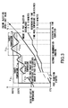
- Fig. 3 is a chart of exhaust gas target temperatures, an accumulated amount of post injection, and regenerating time counted for an automatic regeneration.
- an initial target regeneration temperature is set to, for example, about 500°C to burn PM in the DPD to a certain extent.
- the target temperature is then changed to a final target regeneration temperature that is higher than the initial target regeneration temperature at, for example, about 600°C.
- An amount of post injection is controlled to achieve these target temperatures.
- the ECU 32 sets a PM combustion determination temperature Ta PM that is lower than the initial target regeneration temperature Ta.
- the PM combustion determination temperature Ta PM is shown with a broken line. If the exhaust gas temperature is equal to or higher than the PM combustion determination temperature Ta PM , the ECU 32 determines that PM is burning and accumulates the time elapsed. When the accumulated time reaches a certain value, for example, 2-5 minutes, the ECU 32 changes the target temperature to the final target regeneration temperature Tb. The ECU 32 again sets a PM combustion determination temperature Tb PM that is lower than the final target regeneration temperature Tb.
- the ECU 32 determines that PM is burning and accumulates the time elapsed. When the accumulated time reaches a certain value, for example, 3-10 minutes, the ECU 32 determines that the regeneration is complete.
- the ECU 32 determines that the regeneration is not complete.
- Post injection upper limit temperatures Ta L and Tb L are set above the target regeneration temperatures Ta and Tb, respectively. If, during the automatic regeneration, the exhaust gas temperature reaches or exceeds the post injection upper limit temperature Ta L or Tb L , the post injection is interrupted to prevent melting of the DPD.
- the ECU 32 flashes a manual regeneration warning lamp 36a to advise a driver of a need for manual regeneration.
- a manual regeneration start switch 37 the manual regeneration is started.
- the ECU 32 increases an engine rpm from an idle rpm to a regeneration idle rpm.
- the ECU 32 reduces an opening of the intake throttle valve 18, and closes the EGR valve 23 and the exhaust brake valve 24.
- the ECU 32 enables multiple injections to increase the exhaust gas temperature. Once the exhaust gas temperature is increased, the ECU 32 opens the exhaust brake valve 24 and closes the exhaust throttle valve 26.
- the ECU 32 adds post injection to the multiple injections to increase the exhaust gas temperature to about 500°C so as to burn PM and regenerate the DPD 25.
- the target regeneration temperatures Ta and Tb described with reference to Fig. 3 are also set and the time taken for the regeneration is accumulated.
- the exhaust gas temperature sensor 30b described with reference to Fig. 1 detects an exhaust gas temperature.
- the ECU 32 evaluates a deviation e of the exhaust gas temperature from the target regeneration temperature Ta or Tb described above.
- the ECU 32 uses PID control based on the deviation to determine an amount of operation M for post injection by the fuel injector 38.
- M Kp ⁇ e + Ki ⁇ 1 / Ti ⁇ ⁇ edt + Kd ⁇ Td de / dt
- Kp is a proportional constant for proportional control
- Ki is a proportional constant for integral control
- Kd is a proportional constant for derivative control
- Ti is an integral time
- Td is a derivative time
- t is time.
- a sum of a proportional control term, an integral control term, and a derivative control term determines the amount of operation M.
- An actual amount of post injection is determined by the amount of operation M added to an amount of operation from a base term, and a fuel pressure and a valve opening time of the fuel injector 38.
- the PID control together with a higher engine rpm during the automatic regeneration with a vehicle running, enables the exhaust gas temperature to be increased according to an amount of post injection, allowing the exhaust gas temperature to be accurately controlled to the target regeneration temperature Ta or Tb.
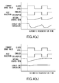
- the post injection is interrupted. This is because, if the post injection is continued, a temperature inside the DPD 25 increases rapidly, posing a risk of the temperature exceeding a post injection upper limit temperature Ta L or Tb L .
- post injection is interrupted when a total amount of fuel injection is lowered to a predetermined value and at the same time PID control is reset to zero.
- the post injection is resumed with the PID control when the total amount of fuel injection reaches or exceeds a predetermined value.
- the problem with this control is that the exhaust gas temperature fluctuates with every acceleration/deceleration.
- the PID control is allowed to continue during deceleration, so that the exhaust gas temperature can be maintained at the target regeneration temperature Ta or Tb.
- the post injection is designed to continue in this case.
- the integral control term is reset to zero when the vehicle is stopped following the deceleration so that the PID control may be appropriate without causing any problem when the vehicle then pulls away.
- the post injection when an amount of post injection is controlled through PID control during automatic regeneration with a vehicle running, the post injection is interrupted if an exhaust brake is closed due to sudden deceleration.
- the PID control is allowed to continue and causes an integral control term to keep integrating a deviation. This allows the PID control to be performed appropriately on the amount of post injection even when the vehicle is accelerated again after the deceleration.
Landscapes
- Engineering & Computer Science (AREA)
- Chemical & Material Sciences (AREA)
- Combustion & Propulsion (AREA)
- Mechanical Engineering (AREA)
- General Engineering & Computer Science (AREA)
- Chemical Kinetics & Catalysis (AREA)
- Processes For Solid Components From Exhaust (AREA)
- Electrical Control Of Air Or Fuel Supplied To Internal-Combustion Engine (AREA)
Applications Claiming Priority (2)
| Application Number | Priority Date | Filing Date | Title |
|---|---|---|---|
| JP2010119721A JP5440385B2 (ja) | 2010-05-25 | 2010-05-25 | 排ガス浄化システム |
| PCT/JP2011/061219 WO2011148816A1 (fr) | 2010-05-25 | 2011-05-16 | Système d'épuration des gaz d'échappement |
Publications (3)
| Publication Number | Publication Date |
|---|---|
| EP2578855A1 true EP2578855A1 (fr) | 2013-04-10 |
| EP2578855A4 EP2578855A4 (fr) | 2018-03-28 |
| EP2578855B1 EP2578855B1 (fr) | 2019-12-04 |
Family
ID=45003807
Family Applications (1)
| Application Number | Title | Priority Date | Filing Date |
|---|---|---|---|
| EP11786515.4A Active EP2578855B1 (fr) | 2010-05-25 | 2011-05-16 | Système d'épuration des gaz d'échappement |
Country Status (5)
| Country | Link |
|---|---|
| US (1) | US8931263B2 (fr) |
| EP (1) | EP2578855B1 (fr) |
| JP (1) | JP5440385B2 (fr) |
| CN (1) | CN102906402B (fr) |
| WO (1) | WO2011148816A1 (fr) |
Cited By (1)
| Publication number | Priority date | Publication date | Assignee | Title |
|---|---|---|---|---|
| WO2015176945A1 (fr) * | 2014-05-19 | 2015-11-26 | Volkswagen Aktiengesellschaft | Procédé et dispositif de gestion de la température des gaz d'échappement d'un moteur à combustion interne |
Families Citing this family (10)
| Publication number | Priority date | Publication date | Assignee | Title |
|---|---|---|---|---|
| JP5585226B2 (ja) * | 2010-06-11 | 2014-09-10 | いすゞ自動車株式会社 | 排ガス浄化システム |
| US9611793B2 (en) * | 2014-08-04 | 2017-04-04 | Caterpillar Inc. | Method for thermal control of exhaust aftertreatment |
| US10513989B2 (en) * | 2015-09-01 | 2019-12-24 | Jacobs Vehicle Systems, Inc. | Method and apparatus for determining exhaust brake failure |
| CN105422228B (zh) * | 2015-11-26 | 2018-04-03 | 潍柴动力股份有限公司 | 防止dpf烧毁的方法和系统 |
| CN111379630A (zh) * | 2018-12-29 | 2020-07-07 | 北京福田康明斯发动机有限公司 | 发动机排气温度控制系统及方法 |
| JP7366876B2 (ja) * | 2020-12-07 | 2023-10-23 | 株式会社クボタ | ディーゼルエンジン |
| CN113006950B (zh) * | 2021-02-24 | 2023-05-05 | 中国重汽集团济南动力有限公司 | 一种发动机排气蝶阀的控制方法和系统 |
| WO2022210919A1 (fr) * | 2021-03-31 | 2022-10-06 | 日揮触媒化成株式会社 | Poudre, son procédé de production et procédé de production de composition de résine |
| CN116498454A (zh) * | 2023-04-17 | 2023-07-28 | 长城汽车股份有限公司 | 控制温度的方法、装置、车辆及存储介质 |
| JP2025085210A (ja) * | 2023-11-24 | 2025-06-05 | いすゞ自動車株式会社 | 車両 |
Family Cites Families (14)
| Publication number | Priority date | Publication date | Assignee | Title |
|---|---|---|---|---|
| JPH04175281A (ja) | 1990-11-09 | 1992-06-23 | Nippon Chem Ind Co Ltd | 転写装飾した施釉セメント成形品及びその製造法 |
| JP2000303826A (ja) | 1999-04-16 | 2000-10-31 | Isuzu Motors Ltd | ディーゼルエンジンの排ガス浄化装置 |
| JP3624892B2 (ja) * | 2001-03-29 | 2005-03-02 | トヨタ自動車株式会社 | 内燃機関の排気浄化装置 |
| KR100504422B1 (ko) * | 2001-09-07 | 2005-07-29 | 미쓰비시 지도샤 고교(주) | 엔진의 배기 정화 장치 |
| JP4135495B2 (ja) * | 2002-12-20 | 2008-08-20 | いすゞ自動車株式会社 | 燃料噴射制御装置 |
| JP4186734B2 (ja) * | 2003-08-04 | 2008-11-26 | いすゞ自動車株式会社 | フィードバック制御装置 |
| JP4175281B2 (ja) | 2004-03-31 | 2008-11-05 | いすゞ自動車株式会社 | 排気ガス浄化システムの制御方法及び排気ガス浄化システム |
| JP2005299457A (ja) * | 2004-04-09 | 2005-10-27 | Isuzu Motors Ltd | エンジンの排気ガス絞り弁 |
| US7246005B2 (en) * | 2005-06-07 | 2007-07-17 | Arvin Technologies, Inc. | Method and apparatus for controlling a component by feed-forward closed-loop controller state modification |
| JP4720476B2 (ja) * | 2005-12-14 | 2011-07-13 | 日産自動車株式会社 | 排ガスフィルタ再生制御装置及び排ガスフィルタ再生制御方法 |
| JP4017010B2 (ja) * | 2006-02-01 | 2007-12-05 | いすゞ自動車株式会社 | 排気ガス浄化システムの制御方法及び排気ガス浄化システム |
| JP4304527B2 (ja) * | 2006-07-03 | 2009-07-29 | トヨタ自動車株式会社 | 内燃機関の排気浄化装置 |
| JP2008144726A (ja) * | 2006-12-13 | 2008-06-26 | Toyota Motor Corp | 内燃機関の排気浄化装置 |
| JP2009103093A (ja) * | 2007-10-25 | 2009-05-14 | Mitsubishi Fuso Truck & Bus Corp | ディーゼルエンジンの制御装置 |
-
2010
- 2010-05-25 JP JP2010119721A patent/JP5440385B2/ja not_active Expired - Fee Related
-
2011
- 2011-05-16 WO PCT/JP2011/061219 patent/WO2011148816A1/fr not_active Ceased
- 2011-05-16 US US13/699,509 patent/US8931263B2/en active Active
- 2011-05-16 CN CN201180025451.5A patent/CN102906402B/zh active Active
- 2011-05-16 EP EP11786515.4A patent/EP2578855B1/fr active Active
Non-Patent Citations (1)
| Title |
|---|
| See references of WO2011148816A1 * |
Cited By (1)
| Publication number | Priority date | Publication date | Assignee | Title |
|---|---|---|---|---|
| WO2015176945A1 (fr) * | 2014-05-19 | 2015-11-26 | Volkswagen Aktiengesellschaft | Procédé et dispositif de gestion de la température des gaz d'échappement d'un moteur à combustion interne |
Also Published As
| Publication number | Publication date |
|---|---|
| US20130061583A1 (en) | 2013-03-14 |
| WO2011148816A1 (fr) | 2011-12-01 |
| CN102906402B (zh) | 2015-09-30 |
| EP2578855A4 (fr) | 2018-03-28 |
| JP5440385B2 (ja) | 2014-03-12 |
| US8931263B2 (en) | 2015-01-13 |
| CN102906402A (zh) | 2013-01-30 |
| EP2578855B1 (fr) | 2019-12-04 |
| JP2011247143A (ja) | 2011-12-08 |
Similar Documents
| Publication | Publication Date | Title |
|---|---|---|
| EP2578855B1 (fr) | Système d'épuration des gaz d'échappement | |
| EP2581568B1 (fr) | Système de purification de gaz d'échappement | |
| EP2578858B1 (fr) | Système d'épuration des gaz d'échappement | |
| EP2581571B1 (fr) | Système d'épuration des gaz d'échappement | |
| CN102939441B (zh) | 废气净化系统 | |
| EP2581569B1 (fr) | Système dpf | |
| EP2578824B1 (fr) | Système d'épuration des gaz d'échappement dans une région en altitude | |
| JP2011241741A (ja) | Dpfシステム |
Legal Events
| Date | Code | Title | Description |
|---|---|---|---|
| PUAI | Public reference made under article 153(3) epc to a published international application that has entered the european phase |
Free format text: ORIGINAL CODE: 0009012 |
|
| 17P | Request for examination filed |
Effective date: 20121220 |
|
| AK | Designated contracting states |
Kind code of ref document: A1 Designated state(s): AL AT BE BG CH CY CZ DE DK EE ES FI FR GB GR HR HU IE IS IT LI LT LU LV MC MK MT NL NO PL PT RO RS SE SI SK SM TR |
|
| DAX | Request for extension of the european patent (deleted) | ||
| RIC1 | Information provided on ipc code assigned before grant |
Ipc: F02D 41/14 20060101AFI20180215BHEP Ipc: F01N 3/02 20060101ALI20180215BHEP Ipc: F02D 41/10 20060101ALI20180215BHEP Ipc: F02D 41/40 20060101ALI20180215BHEP Ipc: F01N 3/023 20060101ALN20180215BHEP Ipc: F01N 3/10 20060101ALN20180215BHEP Ipc: F02D 41/02 20060101ALI20180215BHEP Ipc: F01N 3/035 20060101ALI20180215BHEP Ipc: F02D 9/06 20060101ALI20180215BHEP |
|
| RA4 | Supplementary search report drawn up and despatched (corrected) |
Effective date: 20180223 |
|
| RIC1 | Information provided on ipc code assigned before grant |
Ipc: F02D 41/40 20060101ALI20190522BHEP Ipc: F01N 3/023 20060101ALN20190522BHEP Ipc: F02D 41/12 20060101ALI20190522BHEP Ipc: F02D 9/06 20060101ALI20190522BHEP Ipc: F02D 41/14 20060101AFI20190522BHEP Ipc: F02D 41/10 20060101ALN20190522BHEP Ipc: F01N 3/10 20060101ALN20190522BHEP Ipc: F01N 3/02 20060101ALI20190522BHEP Ipc: F01N 3/035 20060101ALI20190522BHEP Ipc: F02D 41/02 20060101ALI20190522BHEP |
|
| GRAP | Despatch of communication of intention to grant a patent |
Free format text: ORIGINAL CODE: EPIDOSNIGR1 |
|
| STAA | Information on the status of an ep patent application or granted ep patent |
Free format text: STATUS: GRANT OF PATENT IS INTENDED |
|
| INTG | Intention to grant announced |
Effective date: 20190702 |
|
| GRAS | Grant fee paid |
Free format text: ORIGINAL CODE: EPIDOSNIGR3 |
|
| GRAA | (expected) grant |
Free format text: ORIGINAL CODE: 0009210 |
|
| STAA | Information on the status of an ep patent application or granted ep patent |
Free format text: STATUS: THE PATENT HAS BEEN GRANTED |
|
| AK | Designated contracting states |
Kind code of ref document: B1 Designated state(s): AL AT BE BG CH CY CZ DE DK EE ES FI FR GB GR HR HU IE IS IT LI LT LU LV MC MK MT NL NO PL PT RO RS SE SI SK SM TR |
|
| REG | Reference to a national code |
Ref country code: GB Ref legal event code: FG4D |
|
| REG | Reference to a national code |
Ref country code: CH Ref legal event code: EP |
|
| REG | Reference to a national code |
Ref country code: AT Ref legal event code: REF Ref document number: 1209705 Country of ref document: AT Kind code of ref document: T Effective date: 20191215 |
|
| REG | Reference to a national code |
Ref country code: DE Ref legal event code: R096 Ref document number: 602011063810 Country of ref document: DE |
|
| REG | Reference to a national code |
Ref country code: IE Ref legal event code: FG4D |
|
| REG | Reference to a national code |
Ref country code: NL Ref legal event code: MP Effective date: 20191204 |
|
| REG | Reference to a national code |
Ref country code: LT Ref legal event code: MG4D |
|
| PG25 | Lapsed in a contracting state [announced via postgrant information from national office to epo] |
Ref country code: GR Free format text: LAPSE BECAUSE OF FAILURE TO SUBMIT A TRANSLATION OF THE DESCRIPTION OR TO PAY THE FEE WITHIN THE PRESCRIBED TIME-LIMIT Effective date: 20200305 Ref country code: NO Free format text: LAPSE BECAUSE OF FAILURE TO SUBMIT A TRANSLATION OF THE DESCRIPTION OR TO PAY THE FEE WITHIN THE PRESCRIBED TIME-LIMIT Effective date: 20200304 Ref country code: FI Free format text: LAPSE BECAUSE OF FAILURE TO SUBMIT A TRANSLATION OF THE DESCRIPTION OR TO PAY THE FEE WITHIN THE PRESCRIBED TIME-LIMIT Effective date: 20191204 Ref country code: BG Free format text: LAPSE BECAUSE OF FAILURE TO SUBMIT A TRANSLATION OF THE DESCRIPTION OR TO PAY THE FEE WITHIN THE PRESCRIBED TIME-LIMIT Effective date: 20200304 Ref country code: LT Free format text: LAPSE BECAUSE OF FAILURE TO SUBMIT A TRANSLATION OF THE DESCRIPTION OR TO PAY THE FEE WITHIN THE PRESCRIBED TIME-LIMIT Effective date: 20191204 Ref country code: SE Free format text: LAPSE BECAUSE OF FAILURE TO SUBMIT A TRANSLATION OF THE DESCRIPTION OR TO PAY THE FEE WITHIN THE PRESCRIBED TIME-LIMIT Effective date: 20191204 Ref country code: LV Free format text: LAPSE BECAUSE OF FAILURE TO SUBMIT A TRANSLATION OF THE DESCRIPTION OR TO PAY THE FEE WITHIN THE PRESCRIBED TIME-LIMIT Effective date: 20191204 Ref country code: ES Free format text: LAPSE BECAUSE OF FAILURE TO SUBMIT A TRANSLATION OF THE DESCRIPTION OR TO PAY THE FEE WITHIN THE PRESCRIBED TIME-LIMIT Effective date: 20191204 |
|
| PG25 | Lapsed in a contracting state [announced via postgrant information from national office to epo] |
Ref country code: HR Free format text: LAPSE BECAUSE OF FAILURE TO SUBMIT A TRANSLATION OF THE DESCRIPTION OR TO PAY THE FEE WITHIN THE PRESCRIBED TIME-LIMIT Effective date: 20191204 Ref country code: RS Free format text: LAPSE BECAUSE OF FAILURE TO SUBMIT A TRANSLATION OF THE DESCRIPTION OR TO PAY THE FEE WITHIN THE PRESCRIBED TIME-LIMIT Effective date: 20191204 |
|
| PG25 | Lapsed in a contracting state [announced via postgrant information from national office to epo] |
Ref country code: AL Free format text: LAPSE BECAUSE OF FAILURE TO SUBMIT A TRANSLATION OF THE DESCRIPTION OR TO PAY THE FEE WITHIN THE PRESCRIBED TIME-LIMIT Effective date: 20191204 |
|
| PG25 | Lapsed in a contracting state [announced via postgrant information from national office to epo] |
Ref country code: NL Free format text: LAPSE BECAUSE OF FAILURE TO SUBMIT A TRANSLATION OF THE DESCRIPTION OR TO PAY THE FEE WITHIN THE PRESCRIBED TIME-LIMIT Effective date: 20191204 Ref country code: EE Free format text: LAPSE BECAUSE OF FAILURE TO SUBMIT A TRANSLATION OF THE DESCRIPTION OR TO PAY THE FEE WITHIN THE PRESCRIBED TIME-LIMIT Effective date: 20191204 Ref country code: PT Free format text: LAPSE BECAUSE OF FAILURE TO SUBMIT A TRANSLATION OF THE DESCRIPTION OR TO PAY THE FEE WITHIN THE PRESCRIBED TIME-LIMIT Effective date: 20200429 Ref country code: RO Free format text: LAPSE BECAUSE OF FAILURE TO SUBMIT A TRANSLATION OF THE DESCRIPTION OR TO PAY THE FEE WITHIN THE PRESCRIBED TIME-LIMIT Effective date: 20191204 Ref country code: CZ Free format text: LAPSE BECAUSE OF FAILURE TO SUBMIT A TRANSLATION OF THE DESCRIPTION OR TO PAY THE FEE WITHIN THE PRESCRIBED TIME-LIMIT Effective date: 20191204 |
|
| PGFP | Annual fee paid to national office [announced via postgrant information from national office to epo] |
Ref country code: DE Payment date: 20200625 Year of fee payment: 10 Ref country code: FR Payment date: 20200519 Year of fee payment: 10 |
|
| PG25 | Lapsed in a contracting state [announced via postgrant information from national office to epo] |
Ref country code: SM Free format text: LAPSE BECAUSE OF FAILURE TO SUBMIT A TRANSLATION OF THE DESCRIPTION OR TO PAY THE FEE WITHIN THE PRESCRIBED TIME-LIMIT Effective date: 20191204 Ref country code: IS Free format text: LAPSE BECAUSE OF FAILURE TO SUBMIT A TRANSLATION OF THE DESCRIPTION OR TO PAY THE FEE WITHIN THE PRESCRIBED TIME-LIMIT Effective date: 20200404 Ref country code: SK Free format text: LAPSE BECAUSE OF FAILURE TO SUBMIT A TRANSLATION OF THE DESCRIPTION OR TO PAY THE FEE WITHIN THE PRESCRIBED TIME-LIMIT Effective date: 20191204 |
|
| PGFP | Annual fee paid to national office [announced via postgrant information from national office to epo] |
Ref country code: GB Payment date: 20200522 Year of fee payment: 10 |
|
| REG | Reference to a national code |
Ref country code: DE Ref legal event code: R097 Ref document number: 602011063810 Country of ref document: DE |
|
| REG | Reference to a national code |
Ref country code: AT Ref legal event code: MK05 Ref document number: 1209705 Country of ref document: AT Kind code of ref document: T Effective date: 20191204 |
|
| PLBE | No opposition filed within time limit |
Free format text: ORIGINAL CODE: 0009261 |
|
| STAA | Information on the status of an ep patent application or granted ep patent |
Free format text: STATUS: NO OPPOSITION FILED WITHIN TIME LIMIT |
|
| PG25 | Lapsed in a contracting state [announced via postgrant information from national office to epo] |
Ref country code: DK Free format text: LAPSE BECAUSE OF FAILURE TO SUBMIT A TRANSLATION OF THE DESCRIPTION OR TO PAY THE FEE WITHIN THE PRESCRIBED TIME-LIMIT Effective date: 20191204 |
|
| 26N | No opposition filed |
Effective date: 20200907 |
|
| PG25 | Lapsed in a contracting state [announced via postgrant information from national office to epo] |
Ref country code: PL Free format text: LAPSE BECAUSE OF FAILURE TO SUBMIT A TRANSLATION OF THE DESCRIPTION OR TO PAY THE FEE WITHIN THE PRESCRIBED TIME-LIMIT Effective date: 20191204 Ref country code: AT Free format text: LAPSE BECAUSE OF FAILURE TO SUBMIT A TRANSLATION OF THE DESCRIPTION OR TO PAY THE FEE WITHIN THE PRESCRIBED TIME-LIMIT Effective date: 20191204 Ref country code: SI Free format text: LAPSE BECAUSE OF FAILURE TO SUBMIT A TRANSLATION OF THE DESCRIPTION OR TO PAY THE FEE WITHIN THE PRESCRIBED TIME-LIMIT Effective date: 20191204 |
|
| PG25 | Lapsed in a contracting state [announced via postgrant information from national office to epo] |
Ref country code: LI Free format text: LAPSE BECAUSE OF NON-PAYMENT OF DUE FEES Effective date: 20200531 Ref country code: MC Free format text: LAPSE BECAUSE OF FAILURE TO SUBMIT A TRANSLATION OF THE DESCRIPTION OR TO PAY THE FEE WITHIN THE PRESCRIBED TIME-LIMIT Effective date: 20191204 Ref country code: IT Free format text: LAPSE BECAUSE OF FAILURE TO SUBMIT A TRANSLATION OF THE DESCRIPTION OR TO PAY THE FEE WITHIN THE PRESCRIBED TIME-LIMIT Effective date: 20191204 Ref country code: CH Free format text: LAPSE BECAUSE OF NON-PAYMENT OF DUE FEES Effective date: 20200531 |
|
| REG | Reference to a national code |
Ref country code: BE Ref legal event code: MM Effective date: 20200531 |
|
| PG25 | Lapsed in a contracting state [announced via postgrant information from national office to epo] |
Ref country code: LU Free format text: LAPSE BECAUSE OF NON-PAYMENT OF DUE FEES Effective date: 20200516 |
|
| PG25 | Lapsed in a contracting state [announced via postgrant information from national office to epo] |
Ref country code: IE Free format text: LAPSE BECAUSE OF NON-PAYMENT OF DUE FEES Effective date: 20200516 |
|
| PG25 | Lapsed in a contracting state [announced via postgrant information from national office to epo] |
Ref country code: BE Free format text: LAPSE BECAUSE OF NON-PAYMENT OF DUE FEES Effective date: 20200531 |
|
| REG | Reference to a national code |
Ref country code: DE Ref legal event code: R119 Ref document number: 602011063810 Country of ref document: DE |
|
| GBPC | Gb: european patent ceased through non-payment of renewal fee |
Effective date: 20210516 |
|
| PG25 | Lapsed in a contracting state [announced via postgrant information from national office to epo] |
Ref country code: GB Free format text: LAPSE BECAUSE OF NON-PAYMENT OF DUE FEES Effective date: 20210516 Ref country code: DE Free format text: LAPSE BECAUSE OF NON-PAYMENT OF DUE FEES Effective date: 20211201 |
|
| PG25 | Lapsed in a contracting state [announced via postgrant information from national office to epo] |
Ref country code: TR Free format text: LAPSE BECAUSE OF FAILURE TO SUBMIT A TRANSLATION OF THE DESCRIPTION OR TO PAY THE FEE WITHIN THE PRESCRIBED TIME-LIMIT Effective date: 20191204 Ref country code: MT Free format text: LAPSE BECAUSE OF FAILURE TO SUBMIT A TRANSLATION OF THE DESCRIPTION OR TO PAY THE FEE WITHIN THE PRESCRIBED TIME-LIMIT Effective date: 20191204 Ref country code: FR Free format text: LAPSE BECAUSE OF NON-PAYMENT OF DUE FEES Effective date: 20210531 Ref country code: CY Free format text: LAPSE BECAUSE OF FAILURE TO SUBMIT A TRANSLATION OF THE DESCRIPTION OR TO PAY THE FEE WITHIN THE PRESCRIBED TIME-LIMIT Effective date: 20191204 |
|
| PG25 | Lapsed in a contracting state [announced via postgrant information from national office to epo] |
Ref country code: MK Free format text: LAPSE BECAUSE OF FAILURE TO SUBMIT A TRANSLATION OF THE DESCRIPTION OR TO PAY THE FEE WITHIN THE PRESCRIBED TIME-LIMIT Effective date: 20191204 |