EP2579231A1 - Appareil de traitement d´images pour véhicule - Google Patents
Appareil de traitement d´images pour véhicule Download PDFInfo
- Publication number
- EP2579231A1 EP2579231A1 EP12185981.3A EP12185981A EP2579231A1 EP 2579231 A1 EP2579231 A1 EP 2579231A1 EP 12185981 A EP12185981 A EP 12185981A EP 2579231 A1 EP2579231 A1 EP 2579231A1
- Authority
- EP
- European Patent Office
- Prior art keywords
- vehicle
- assistance
- stereo camera
- stereo
- distance
- Prior art date
- Legal status (The legal status is an assumption and is not a legal conclusion. Google has not performed a legal analysis and makes no representation as to the accuracy of the status listed.)
- Withdrawn
Links
Images


Classifications
-
- G—PHYSICS
- G08—SIGNALLING
- G08G—TRAFFIC CONTROL SYSTEMS
- G08G1/00—Traffic control systems for road vehicles
- G08G1/16—Anti-collision systems
- G08G1/166—Anti-collision systems for active traffic, e.g. moving vehicles, pedestrians, bikes
-
- G—PHYSICS
- G06—COMPUTING OR CALCULATING; COUNTING
- G06T—IMAGE DATA PROCESSING OR GENERATION, IN GENERAL
- G06T7/00—Image analysis
- G06T7/50—Depth or shape recovery
- G06T7/55—Depth or shape recovery from multiple images
- G06T7/593—Depth or shape recovery from multiple images from stereo images
-
- G—PHYSICS
- G06—COMPUTING OR CALCULATING; COUNTING
- G06V—IMAGE OR VIDEO RECOGNITION OR UNDERSTANDING
- G06V20/00—Scenes; Scene-specific elements
- G06V20/50—Context or environment of the image
- G06V20/56—Context or environment of the image exterior to a vehicle by using sensors mounted on the vehicle
- G06V20/58—Recognition of moving objects or obstacles, e.g. vehicles or pedestrians; Recognition of traffic objects, e.g. traffic signs, traffic lights or roads
-
- G—PHYSICS
- G06—COMPUTING OR CALCULATING; COUNTING
- G06V—IMAGE OR VIDEO RECOGNITION OR UNDERSTANDING
- G06V20/00—Scenes; Scene-specific elements
- G06V20/50—Context or environment of the image
- G06V20/56—Context or environment of the image exterior to a vehicle by using sensors mounted on the vehicle
- G06V20/588—Recognition of the road, e.g. of lane markings; Recognition of the vehicle driving pattern in relation to the road
-
- H—ELECTRICITY
- H04—ELECTRIC COMMUNICATION TECHNIQUE
- H04N—PICTORIAL COMMUNICATION, e.g. TELEVISION
- H04N13/00—Stereoscopic video systems; Multi-view video systems; Details thereof
- H04N13/20—Image signal generators
- H04N13/204—Image signal generators using stereoscopic image cameras
- H04N13/239—Image signal generators using stereoscopic image cameras using two two-dimensional [2D] image sensors having a relative position equal to or related to the interocular distance
-
- H—ELECTRICITY
- H04—ELECTRIC COMMUNICATION TECHNIQUE
- H04N—PICTORIAL COMMUNICATION, e.g. TELEVISION
- H04N13/00—Stereoscopic video systems; Multi-view video systems; Details thereof
- H04N13/20—Image signal generators
- H04N13/204—Image signal generators using stereoscopic image cameras
- H04N13/243—Image signal generators using stereoscopic image cameras using three or more two-dimensional [2D] image sensors
-
- B—PERFORMING OPERATIONS; TRANSPORTING
- B60—VEHICLES IN GENERAL
- B60W—CONJOINT CONTROL OF VEHICLE SUB-UNITS OF DIFFERENT TYPE OR DIFFERENT FUNCTION; CONTROL SYSTEMS SPECIALLY ADAPTED FOR HYBRID VEHICLES; ROAD VEHICLE DRIVE CONTROL SYSTEMS FOR PURPOSES NOT RELATED TO THE CONTROL OF A PARTICULAR SUB-UNIT
- B60W2554/00—Input parameters relating to objects
-
- G—PHYSICS
- G06—COMPUTING OR CALCULATING; COUNTING
- G06T—IMAGE DATA PROCESSING OR GENERATION, IN GENERAL
- G06T2207/00—Indexing scheme for image analysis or image enhancement
- G06T2207/30—Subject of image; Context of image processing
- G06T2207/30248—Vehicle exterior or interior
- G06T2207/30252—Vehicle exterior; Vicinity of vehicle
Definitions
- the present invention relates to an image processing apparatus that includes plural stereo cameras, and detects a distance to a target around a vehicle.
- a driving assistance system monitors in the forward facing direction from a vehicle using a camera that is installed at a front part of the vehicle, and measures distances to a pedestrian, another vehicle, an obstacle and so forth. Then, when there is a possibility of collision therewith, the system is capable of informing the driver of this matter, applying a brake to decelerate or stop the vehicle, and/or the like.
- ASV Advanced Safety Vehicle
- a door opening/closing assistance system which informs a passenger of a vehicle whether a sufficient space is left for opening/closing a vehicle door or a luggage compartment door or gives a passenger a warning that another vehicle or a pedestrian is approaching from behind when the passenger is entering or exiting the vehicle.
- a method is known of calculating a distance with high precision.
- plural cameras installed at different positions i.e., a compound-eye camera, referred to as a "stereo camera”, hereinafter
- stereo camera plural cameras installed at different positions
- the distance is calculated using differences in positions (parallax) on sensors at which images are formed.
- Position detection devices that use stereo cameras have been used not only for vehicles but also for robots, security cameras, and so forth.
- Plural stereo cameras are needed for realizing various driving assistance system and door opening/closing assistance system.
- a system using plural stereo cameras not only may require complicated control but also may be high-priced.
- a method of selecting from images of plural stereo cameras depending on the situation and reducing the cost by sharing stereo matching and/or a distance information generation part may be considered (see Patent Reference No. 1 (Japanese Laid-Open Patent Application No. 2003-348575 )).
- Parent Reference No. 1 discloses a stereo vehicle exterior monitoring apparatus in which a selection from plural stereo cameras is carried out in a time division manner, and stereo matching and/or a distance information generation part are shared.
- an image processing apparatus has plural stereo cameras, and detects a distance to a target around a vehicle.
- the image processing apparatus further includes sensors installed in the vehicle; a situation judgment and image selection part that determines a vehicle situation by combining detection signals of the sensors and switches image data to be processed from image data photographed by a stereo camera for driving assistance to image data photographed by a stereo camera for door opening/closing assistance; a preprocessing part that carries out distortion corrections that are unique to the plural stereo cameras respectively on the image data selected by the situation judgment and image selection part so that a correlation calculation part can carry out correlation calculation that is common to the plural stereo cameras; the correlation calculation part that carries out correlation calculation on two sets of image data photographed by the single stereo camera; and a distance detection part that detects the distance to the target by using a calculation result of the correlation calculation part.
- FIG. 1 illustrates one example of a stereo camera system according to an embodiment.
- Plural stereo cameras 40-1, 40-2 and 40-3 are installed in a vehicle.
- the stereo cameras 40-1, 40-2 and 40-3 are fixed in the vehicle (not shown) in such a manner that the stereo cameras 40-1, 40-2 and 40-3 photograph images in the same direction or different directions, respectively.
- the stereo camera system determines a situation of the vehicle from detection results of the various sensors. Then, according to the determination result, the stereo camera system determines which one of the following three assistances is to be carried out.
- the stereo camera system determines which one(s) of the images photographed by the three stereo cameras 40-1, 40-2 and 40-3 is(are) to be output to an image processing part 120 (i.e., a preprocessing part 12 and so forth described later), depending a manner of the assistance to be carried out.
- the image processing part 120 carries out distortion corrections unique to the respective plural stereo cameras according to the manner of the assistance to be carried out.
- assistance in improving safety by detecting the distance to an obstacle such as another vehicle that runs ahead and carrying out a warning or automatic braking
- assistance of detecting a white line(s) (a road mark(s) such as a line or points that separate(s) traffic lanes, a small projection, a reflecting object or the like) and/or the shoulder of a road, and preventing a vehicle from deviating from the traffic lane or the like
- driving assistance Any assistance other than parking assistance and door opening/closing assistance corresponds to driving assistance.
- a stereo camera which photographs in a forward facing direction from the vehicle is used. However, various stereo cameras may be used depending on the specific contents of the assistance.
- Assistance of, after the vehicle has been stopped, detecting the distance from a door to a target (a wall, a side surface of another vehicle or the like), an inclination of the surface thereof, a direction of the surface, and/or the like, and encouraging the driver to again carry out parking or the like corresponds to parking assistance.
- a target a wall, a side surface of another vehicle or the like
- an inclination of the surface thereof, a direction of the surface, and/or the like and encouraging the driver to again carry out parking or the like corresponds to parking assistance.
- stereo cameras that photograph in a forward facing direction and/or a lateral direction(s) from the vehicle are used.
- the stereo camera system carries out assistance to enter a mode in which the stereo camera 40-1 and the stereo camera 40-2 or 40-3 (selected depending on whether the parking is right turn parking or left turn parking) are used alternately, a mode in which a white line(s) is(are) displayed on a display device (not shown), which line(s) is(are) used as a target of a parking position, or so.
- a stereo camera(s) that photograph(s) in the corresponding lateral direction from the vehicle is(are) used.
- FIG. 2 schematically shows one example of positions at which the three stereo cameras are installed.
- the stereo camera 40-1 is put at a front part of the vehicle 200
- the stereo camera 40-2 is put at a left side part viewed from a driver's seat
- the stereo camera 40-3 is put at a right side part viewed from the driver's seat.
- the stereo camera 40-1 is put on a rearview mirror in the inside of the vehicle or a bumper at the front part of the vehicle, in such a manner that its optical axis is pointed approximately horizontally in the forward facing direction from the vehicle.
- the stereo camera 40-2 is put on, for example, a right door mirror, a hollow in which a door knob is installed on a right side surface of the vehicle, a frame of a door window, an "A" pillar 51, a "B” pillar 52 a “C” pillar 53 or the like, for example, in such a manner that the optical axis is pointed in the right lateral direction from the vehicle or a direction that is inclined somewhat backward or forward from the right lateral direction from the vehicle.
- the stereo camera 40-3 is put on, for example, a left door mirror, a hollow in which a door knob is installed on a left side surface of the vehicle, a frame of a door window, an "A" pillar 51, a "B” pillar 52 a “C” pillar 53 or the like, for example, in such a manner that the optical axis is pointed in the left lateral direction from the vehicle or a direction that is inclined somewhat backward or forward from the left lateral direction from the vehicle.
- the stereo camera 40-1 is used for driving assistance and also parking assistance.
- the stereo cameras 40-2 and 40-3 are used for parking assistance and door opening/closing assistance.
- a range to be covered by each stereo camera is increased depending on the field angle.
- the relationships between the assistance and the stereo cameras to be used therefor, respectively, are not necessarily fixed.
- the relationships between the assistance and the positions of the stereo cameras mentioned above are merely examples.
- a stereo camera for back guide monitoring may be installed around a rear number plate, a rear bumper or the like. That is, the number of stereo cameras to be used may be 4 or more. Optical characteristics such as the field angles, focal lengths, zooming functions and/or the like of the lenses of the stereo cameras may be such that the optical characteristics of the two lenses included in the same stereo camera should be equal to one another.
- the respective stereo cameras 40-1, 40-2 and 40-3 may have any optical characteristics. That is, stereo cameras having different optical characteristics such as lenses of wide field angles such as fisheye lenses, narrow field angles and/or the like may be used as the stereo cameras 40-1, 40-2 and 40-3.
- the stereo camera 40-1 which is in a forward facing direction from the vehicle is used mainly for measuring the distance to a pedestrian, the distance to another vehicle that runs ahead, the distance to another feature (a road mark, a traffic light, a power pole, a guardrail or the like) or an obstacle.
- Image processing for example, white line recognition, pedestrian recognition or so
- other than measuring the distance to a target may be carried out using a luminance image of the stereo camera 40-1.
- the stereo camera 40-1 is used for parking assistance, the stereo camera 40-1 is used to detect the width of a space for determining whether there is such a room in a parking space sandwiched between two vehicles or walls that the vehicle can be parked, for example.
- the stereo camera 40-1 may include plural stereo cameras that have different distance measurement ranges and/or photographing ranges which are installed in the same orientation and may be used for different purposes, respectively.
- each one of the stereo cameras 40-1, 40-2 and 40-3 has plural stereo cameras having different field angles and focal lengths.
- the plural stereo cameras 40-1 may be installed in different orientations.
- the stereo camera 40-1 may be installed in such a manner to monitor the complete periphery of the vehicle, the stereo camera 40-1 may be installed at a rear part to recognize the distance to a following vehicle and/or the like, in addition to installing the stereo camera 40-1 to face the front side so as to recognize the distance to a front target.
- the stereo cameras 40-2 and 40-3 are used to recognize a human being or a thing that is approaching from around the vehicle when the driver or a passenger will open a door. It is noted that a "passenger” means an occupant of the vehicle other than the driver. Each of the driver and the passenger will be simply referred to as an "occupant" when the driver and the passenger are not distinguished therebetween.
- the stereo cameras 40-2 and 40-3 measure the distance to an adjacent vehicle in a car park or so, and measures distances to a bicycle, a motor cycle and a pedestrian, approaching from the back side after the vehicle is parked. Thus, directions of targets to which the distances are to be measured are somewhat different, and thus, the stereo cameras 40-2 and 40-3 may use wide angle lenses.
- the stereo cameras 40-2 and 40-3 are used not only to determine whether a door can be opened/closed but also to determine a timing at which the door can be opened/closed. Thus, it is possible to achieve the two different purposes by using the single lens as a result of changing the distortion correction precision depending on the field angle.
- such a distortion correction method may be used that, for a range of a narrow angle, distortion is corrected with high precision; and for a range of a wide angle, distortion is corrected with such a degree of precision that a target can be detected and a speed of the target can be calculated.
- a system that detects occupants and/or a system that recognizes occupants may be installed.
- the occupant detection camera detects occupants (including an intruder who is not authorized), and detects the build(s), height(s), width(s) and/or the like of the passenger(s) and/or the driver.
- a position of installing the occupant detection camera is a position such that it is possible to photograph the inside of the vehicle from the front side toward the rear side (for example, at a rearview mirror, a sun visor, the "A" pillar 51, the ceiling or the like), or a position such that it is possible to photograph the inside of the vehicle from the lateral side toward the front side (for example, at the "C" pillar 53, a rear seat door frame, the ceiling or the like).
- the occupant detection camera at a position such that it is possible to photograph from the lateral side toward the inside of the vehicle (for example, at a door, the "A" pillar 51, the "B” pillar 52 or the “C” pillar 53), and photograph the passenger(s) and/or the driver from the lateral side.
- the occupant detection camera may be a stereo camera of a monocular camera.
- a monocular camera the build, height, width and/or the like of a human being can be detected by detecting the human being as a dynamic body to obtain information in various postures.
- a stereo camera not only brightness information of an image but also distance information can be obtained.
- the stereo cameras 40-1, 40-2 and 40-3 are calibrated using image data that is photographed by the respective pairs of cameras as calibration data, at a time of shipment or after being installed in the vehicle. That is, a Look Up Table (LUT) for geometric transform is previously generated for converting given image data in such a manner to minimize internal error causes concerning hardware of the pairs of cameras such as lens distortions, optical axis shifts, focal length shifts, distortions of the image pickup devices and so forth. Further, also a polynomial that will be described later may be used. The LUT and/or the polynomial are/is stored in a memory 150-2 of FIG. 4 (described later). The preprocessing part converts image data that has been input, using the LUT or polynomial, before carrying out correlation calculation.
- LUT Look Up Table
- FIG. 3 shows one example of a hardware configuration of a stereo camera system 100.
- Many microcomputers are installed in a vehicle, and in many cases, one unit in which one or more microcomputers are installed may be called an Electronic Control Unit (ECU).
- ECU Electronice Control Unit
- an engine ECU that controls an engine a brake ECU that controls a brake, a body ECU that controls doors, seats and/or the like, an information ECU that controls a navigation system, Audio and Video (AV) equipment and/or the like, and/or the like are known.
- An ECU 43 shown in FIG. 3 represents them.
- Various sensors 44 and/or actuators are connected to the ECU 43.
- the sensors and/or actuators that are connected to the ECU 43 are designed so as to be suitable to control the respective ECUs of the ECU 43 or convenient for being handled with a harness or the like, and thus, are not necessarily fixed ones.
- an engine rotating speed sensor, a throttle position sensor, an air flow sensor, a water temperature sensor, an O 2 sensor and/or the like are connected to the engine ECU.
- a vehicle speed sensor, a brake sensor, a master cylinder pressure sensor, a pump oil pressure sensor, a wheel cylinder pressure sensor and/or the like are connected.
- a door lock sensor, a courtesy sensor and/or the like are connected.
- the ECU 43 that is installed in a vehicle is connected in such a manner that communication is available via an in-vehicle LAN of a standard of Controller Area Network (CAN), FrexRay or the like.
- the ECU 43 transmits predetermined signals of the various sensors and/or processing results of the signals to the in-vehicle LAN.
- the data transmitted to the in-vehicle LAN can be read by all the ECUs of the ECU 43 connected to the in-vehicle LAN, and the respective ECUs of the ECU 43 receive predetermined data, and use the received data for data processing.
- a camera control ECU 42 of FIG. 3 is connected to the in-vehicle LAN in a manner the same as or similar to that of the ECU 43, and can carry out communication with other ECUs.
- the camera control ECU 42 is connected with a display device 41 and the stereo cameras 40-1, 40-2 and 40-3.
- one or more microcomputers are installed, has, the same as or similar to a common vehicle microcomputer, a CPU 42-5, a RAM 42-2, a ROM 42-4, a CAN Controller (CANC) 42-3 and I/Os 42-6, 42-7 and 42-8, and also has an image processing IC 20 for carrying out image processing. These are connected together by a system bus and/or an external bus and a bus controller.
- the stereo cameras 40-1, 40-2 and 40-3 are connected to the I/Os 42-6, 42-7 and 42-8, respectively, and photographed image data is used by the image processing IC 20 to carry out image processing thereon using the RAM 42-2 if necessary.
- the CPU 42-5 executes a program stored in the ROM 42-4 using the RAM 42-2 as work memory, and carries out various sorts of control described later.
- the CANC 42-3 carries out communication with the ECU 43 based on CAN protocol.
- the display device 41 is a display device using a liquid crystal, organic EL or the like, or using a Heads Up Display (HUD), for displaying pictures/images photographed by the stereo cameras 40-1, 40-2 and 40-3.
- HUD Heads Up Display
- the display device 41 is used to display, for example, a pedestrian and/or an obstacle detected through the image processing in a manner of emphasizing them(it). However, the display device 41 is not necessarily required. Further, in many cases, the display device 41 is also used as a display device of the navigation system that displays a road map.
- the stereo camera system 100 of FIG. 3 is installed in the vehicle 200 of FIG. 2 although the stereo camera system 100 is omitted in FIG. 2 for convenience of explanation.
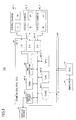
- FIG. 4 is one example of a functional block diagram of the stereo camera system 100.
- the stereo camera system 100 includes a situation judgment and image selection part 11, a preprocessing part 12, a correlation calculation part 13, a recognition part 14 and a display and warning control part 15.
- the situation judgment and image selection part 11 is connected to a vehicle speed sensor 21, a steering rudder angle detection sensor 22, a shift position sensor 23, a direction indicator sensor 24, a brake sensor 25, a parking brake sensor 26, a temperature sensor 27, a door lock sensor 28, a pyroelectric sensor 29, a microswitch 30, an occupant detection sensor 32, a memory 150-1, and the stereo cameras 40-1, 40-2 and 40-3.
- the vehicle speed sensor 21 is a sensor that, for example, outputs a pulse each time a wheel is rotated a predetermined angle.
- the situation judgment and image selection part 11 can obtain the vehicle speed by counting the number of pulses received every unit period of time.
- the steering rudder angle detection sensor 22 detects the rudder angle as a result of light that is detected by a photodiode being blocked along with rotation of a steering shaft, for example.
- the shift position sensor 23 detects the position of a shift lever (P, N, D, R and/or the like), and outputs an electric signal according to the detected shift position.
- the direction indicator sensor 24 detects, for example, an operating direction of a turn signal switch of a swinging type (winker switch) that extends from a steering column.
- the brake switch 25 is a sensor that outputs an "on" signal when a brake pedal is pressed (stop lamp switch) or a sensor that detects the brake pedal being pressed using the master cylinder pressure.
- the temperature sensor 27 detects a temperature of the inside of the vehicle or the ambient temperatures of the stereo cameras 40-1, 40-2 and 40-3.
- the door lock sensor 28 detects the locked/unlocked state of each door.
- the pyroelectric sensor 29 receives infrared rays and outputs a voltage, and is set at a door opening lever, an internal door knob or the like. The pyroelectric sensor 29 detects that the passenger or the driver puts his or her hand on the door.
- the microswitch 30 is set at the door opening lever, the internal door knob or the like and detects that the passenger or the driver puts his or her hand on the door.
- the occupant detection sensor 32 is a load sensor, an indoor camera or the like which is set at each of the driver's seat, the front passenger's seat, the rear center seat, the rear right seat and the rear left seat for detecting whether an occupant exists for each seat.
- the situation judgment and image selection part 11 determines the running state of the vehicle based on a result of recognizing signals of the various sensors and image data photographed by the stereo cameras 40-1, 40-2 and 40-3. Further, the situation judgment and image selection part 11 carries out action prediction of the driver and/or the passenger(s) and selects the image data of one stereo camera from among the plural stereo cameras 40-1, 40-2 and 40-3.
- the preprocessing part 12 carries out image processing on two sets of image data photographed by the stereo cameras 40-1, 40-2 and 40-3, respectively, so that the correlation calculation part 13 can carry out common correlation calculation.
- the correlation calculation part 13 carries out correlation calculation on two sets of image data that have been processed by the preprocessing part 12.
- the recognition part 14 recognizes the target based on the calculation result of the correlation calculation.
- the display and warning control part 15 displays the recognition result on the display device 41, sounds an alarm or controls the brake or opening/closing of a door based on the recognition result.
- FIG. 5 illustrates the principle of distance measurement by a stereo camera in which cameras are arranged in parallel. Cameras C0 and C1 are installed with a distance B therebetween. The focal lengths, optical centers and image pickup planes of the cameras C0 and C1 are as follows:
- An image of an object A that is at a position distant from the optical center O 0 of the camera C0 by a distance d is formed at a point P 0 that is the intersection between a straight line A-O 0 and the image pickup plane s 0 .
- the same object A is formed at a point P 1 on the image pickup plane s 1 .
- the intersection between a straight line that passes through the optical center O 1 of the camera C1 and parallel to the straight line A-O 0 and the image pickup plane s 1 is referred to as a point P 0 ', and the distance between the point P 0 ' and the point P 1 is referred to as a distance p.
- the point P 0 ' is the same position as the point P 0 in the camera C0.
- the distance p represents the shift in position on the images of the same object A photographed by the two cameras C0 and C1 and is called parallax.
- the distance d can be obtained from the parallax p.
- an image of an object outside of the camera is projected onto an image pickup plane.
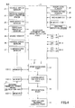
- FIG. 6 illustrates one example of selection of images based on situation judgments.
- the situation judgment and image selection part 11 determines the running state of the vehicle and carries out action prediction as to what the passenger or the driver wishes to do and selects the image of one of the plural stereo cameras 40-1, 40-2 and 40-3 based on the determination (judgment) results.
- the blocks of thin lines indicate selection results of assistance
- the blocks of thick lines indicate targets of situation judgments.
- the correspondences between the contents of assistance and the stereo camera(s) to be selected are as follows.
- the time interval of carrying out situation judgment is shortened in a case where the vehicle speed is zero.
- the time interval of carrying out situation judgment is elongated.
- Each time interval may be measured by, for example, counting the number of frames photographed periodically (the number of sets of image data photographed by a single camera).
- the resources may be used for another purpose. It is also possible to carry out situation judgment and image selection every several frames constantly.
- the stereo camera 40-1 for driving assistance may include plural stereo cameras for the forward facing direction, rear direction, lateral directions and/or the like.
- the situation judgment and image selection part 11 carries out a process such as that of selecting one stereo camera to be used for measuring a distance from among the plural stereo cameras in a case where the vehicle speed indicates a value greater than or equal to the threshold.
- the resources for the selection of a stereo camera it is possible to use the resources for the selection of a stereo camera.
- one stereo camera may be selected at once.
- a method of narrowing down candidates is also effective, as will be described below. That is, first stereo cameras as candidates for distance measurement are extracted according to a situation judgment result, identifying information of the extracted stereo cameras is stored in the memory 150-1, and then, one stereo camera is selected from the extracted stereo cameras. This is because when switching the stereo camera 40-1 for driving and parking assistance and the stereo cameras 40-2 and 40-3 for door opening/closing assistance, the case is not limited to a case where one is selected from two.
- a possibility that plural ones are installed for each of the stereo camera 40-1 for driving and parking assistance and the stereo cameras 40-2 and 40-3 for door opening/closing assistance is high. Since the number of doors may be 4, a possibility that 4 sets at most and at least 2 sets are set for each of the stereo cameras 40-2 and 40-3 for door opening/closing assistance.
- one stereo camera may be further selected from the extracted plural stereo cameras using temperature information from the temperature sensor 27 and/or information from the microswitch 30 and/or the pyroelectric sensor 29.
- door opening/closing assistance could not be carried out in a case where the passenger or the driver gets out the vehicle while the shift position is in "drive".
- FIGs. 7A, 7B and 7C illustrate one example of processing the signal from the brake sensor 25 and a brake frequency.
- the black dots represent detection timings of the signal of the brake pedal.
- the black dots are plotted on "1" when it has been determined that the brake pedal has been pressed.
- the black dots are plotted on "0" when it has been determined that the brake pedal has not been pressed.
- the signal from the brake sensor 25 is obtained twice every millisecond.
- the number of times the signal from the brake sensor 25 corresponds to "1" i.e., the brake pedal has been pressed
- the thus obtained count value will be referred to as a brake frequency.
- FIG. 7A all the black dots are of "1" during 5 milliseconds.
- FIG. 7B 5 black dots are of "1" during 5 milliseconds.
- FIG. 7C two black dots are of "1" during 5 milliseconds.
- the number of times of pressing the brake pedal per fixed period of time is greater than during a state of the vehicle's running in a normal driving state.
- the brake frequency has a greater value than during a state of the vehicle's running in a normal driving state.
- the brake frequency should have a smaller value than a state of continuously pressing the brake.
- the number of "1"s that is smaller than the 10 times/5 milliseconds and larger than 0 is obtained.
- the brake may be pressed even while the vehicle is running in a normal driving state, there is a possibility that the brake frequency obtained when a target period of time is defined to a certain period of time has a by far smaller value in comparison to the state of operating the vehicle for parking.
- the number of "1"s greater than 0 is obtained during 5 milliseconds.
- a threshold a value of the brake frequency for distinguishing between a situation of continuously pressing the brake pedal and a situation of pressing the brake pedal but not continuously pressing the brake pedal, for example, during operating the vehicle for parking, with reference to the numbers of "1"s in FIGs. 7A, 7B and 7C .
- the threshold for determining whether the brake pedal is being continuously pressed will be referred to as a threshold "a”.
- the threshold for distinguishing a state of operating the vehicle for parking and a stopped state (after the parking) will be referred to as a threshold "b”.
- the threshold "a” is, for example, on the order of 9 through 10.
- the threshold "b” is, for example, on the order of 1 through 2.
- door opening/closing assistance could not be carried out in a case where the passenger or the driver gets out the vehicle while the shift position is in "drive".
- step S1 no information as to whether the door lock has been unlocked.
- the door lock is inevitably unlocked in a case where a door is to be opened and closed.
- the situation judgment and image selection part 11 will carry out distance measurement using the stereo camera 40-1 for driving and parking assistance (in FIG. 6 , "a").
- the situation judgment it is preferable to determine by combining the signals obtained from the vehicle speed sensor 21, the steering rudder angle sensor 22, the shift position sensor 23, the direction indicator sensor 24, the brake sensor 25, the parking brake sensor 26 and the door lock sensor 28.
- the determination is to be carried out, it is possible to carry out further precise situation judgment by using, together with the above-mentioned sensor information, a result of characteristic object recognition that may be carried out on an image(s) of the stereo camera(s) of several frames before.
- the images to be used for characteristic object recognition may be a parallax image(s) or a luminance image(s).
- step S3-1 determines whether the brake frequency is less than or equal to the threshold "a" (step S3-1). In a case where the brake frequency is less than or equal to the threshold "a" (step S3-1 yes), it is determined that the driver does not have an intention to carry out parking and driving assistance will be carried out ( FIG. 6 , "c"). In a case where the brake frequency is greater than the threshold "a" (step S3-1 no), it is determined that the driver has an intention to carry out parking and parking assistance will be carried out ( FIG. 6 , "b").
- step S2 In a case where the door lock has been unlocked (step S1 yes), first the vehicle speed information is obtained (step S2). In a case where the vehicle speed is 0 (step S2 yes), information concerning whether the shift position obtained from the shift position sensor 23 is in "park” (step S3-2). In a case where the shift position is in "park” (step S3-2 yes), it is determined that parking has been completed and door opening/closing assistance will be carried out ( FIG. 6 , "d”). There is a case where the shift position is made to be “park” during a traffic jam or when stopping at a red light continues for a long time. However, the shift position is inevitably changed to "drive” when the vehicle is then to enter a normal driving state. Thus, there will be no problem when switching is made into the stereo cameras 40-2 and 40-3 for door opening/closing assistance in response to having detected that the shift position is in "park”.
- the vehicle In order to carry out the determination further precisely, it is possible to determine that the vehicle is in a parked state from detecting a characteristic object from an image recognition result of the recognition part 14 or from a fact that there are many static objects around the vehicle. Further, it is also possible to make the determination using information not from the shift position sensor 23 but from the brake sensor 25. There is a high possibility that the vehicle is in a parked state when the brake pedal is not pressed although the vehicle speed is zero and the parking brake has been applied.
- step S1 the state of the door lock is determined (step S1) and the vehicle speed is determined (step S2).
- step S2 it is determined from the shift position sensor 23 whether the shift position is at a position other than "park” (step S3-2).
- step S3-2 it is possible to determined that parking has been completed.
- step S3-2 the information from the brake sensor 25 is obtained (step S4). At this time, instead of determining whether the brake pedal has been pressed at a certain time point, information is obtained as to how frequently a state of the brake pedal being pressed has occurred during a certain period of time.
- step S4 yes in a case where the brake frequency is greater than or equal to the threshold "b":
- the situation judgment and image selection part 11 determines that the driver is in a state of continuously pressing the brake pedal in a case where the brake frequency is greater than or equal to the threshold "b".
- a characteristic object recognition result that has been processed by the recognition part 14 (described later) obtained from image data (the image data to be used for recognition may be any one of image data before the correlation calculation and image data after the correlation calculation) photographed by the stereo camera(s) for driving assistance is obtained (step S5-2).
- the characteristic object(s) may be, specifically, a traffic light, a stripe pattern of a pedestrian crossing, a temporary stop line, a stop sign, a railroad crossing and/or the like.
- step S5-2 yes it is determined that the vehicle has stopped at a red light, is in a temporarily stopped state, has stopped at a railroad crossing or the like, and the stereo camera 40-1 for driving assistance and the stereo cameras 40-2 and 40-3 for door closing/opening assistance are selected.
- the stereo camera(s) to be used may be narrowed down from among those included in the stereo cameras 40-2 and 40-3 for door closing/opening assistance to a stereo camera(s) at the position(s) of the passenger(s) and/or the driver who have(has) been detected by the occupant detection sensor 32 installed in the vehicle.
- the passenger(s) and/or the driver may move in the vehicle (in particular, among the rear seats). Thus, it is necessary to detect the passenger(s) and/or the driver every certain time interval.
- step S5-2 no it is not immediately determined that the current state is other than a state of having stopped at a red light or the like. This is because there are limits of detecting, by image recognition, a traffic light, a railroad crossing, a pedestrian crossing and/or the like.
- the situation judgment and image selection part 11 determines from a recognition result(s) of the stereo camera(s) whether there is an object that is currently moving in a direction of crossing a direction in which the vehicle is moving (step S6).
- step S6 yes it is determined that the vehicle has temporarily stopped during a normal driving state and also the stereo cameras 40-2 and 40-3 for door opening/closing assistance will be selected as candidate cameras. Then, driving assistance will be carried out when opening/closing of a door has not been detected by the microswitch 30 and/or the pyroelectric sensor 29 ( FIG. 6 , "i").
- step S6 no it is determined that a possibility that the passenger(s) and/or the driver will exit the vehicle is high, and switching is made into the stereo cameras for the doors other than the door of the driver's seat from among the stereo cameras 40-2 and 40-3 for door opening/closing assistance ( FIG. 6 , "h").
- the reason why the driver is thus excluded is that a possibility that the driver will open the door and exit the vehicle with the shift position other than in "park” while continuously pressing the brake pedal is very low.
- step S4 no and step S5-1 no in a case where the brake frequency is greater than the threshold "a" and smaller than the threshold "b":
- the brake frequency is greater than the threshold "a” and smaller than the threshold "b"
- the stereo camera 40-1 for parking assistance will also be used as at least one of the stereo cameras 40-2 and 40-3 for door opening/closing assistance
- a process may be carried out for correcting distortion with high precision by the preprocessing part 12 also for a wide angle area, or the stereo camera 40-1 for parking assistance may be used as at least one of the stereo cameras 40-2 and 40-3 for door opening/closing assistance as it is.
- the vehicle In a case where the brake frequency is smaller than or equal to the threshold "a", the vehicle is in a stopped state, and a possibility that a person(s) other than the driver exits the vehicle is high. Thus, door opening/closing assistance for the doors other than the driver's seat is carried out ( FIG. 6 , "f"). For example, in a case where the parking brake has been applied and the vehicle is in a stopped state although the brake pedal is not pressed, such this condition may be met.
- Opening/closing of a door is carried out basically in a state of the vehicle not moving.
- switching is made from the stereo camera for driving assistance into the stereo cameras for door opening/closing assistance as mentioned above.
- At least one of the stereo cameras 40-2 and 40-3 for door opening/closing assistance is also used for as the stereo camera 40-1 for parking assistance
- at least one of the stereo cameras 40-2 and 40-3 for door opening/closing assistance is used even in a case where the vehicle speed is not zero.
- the stereo cameras 40-2 and 40-3 for door opening/closing assistance are installed at side parts of the vehicle (as shown in FIG. 2 ), and the target distance measurement ranges thereof are a short distance.
- the stereo camera 40-1 for parking assistance is installed for the purpose of avoiding collision with another vehicle or a person around the occupant vehicle.
- the stereo camera 40-1 for parking assistance has the lens specifications the same or similar to those of the stereo cameras 40-2 and 40-3 for door opening/closing assistance.
- the stereo cameras 40-2 and 40-3 for door opening/closing assistance and the stereo camera 40-1 for parking assistance.
- the plural stereo cameras 40-1 for driving assistance and parking assistance are installed at a front part, and the stereo cameras 40-2 and 40-3 for door opening/closing assistance are installed at side parts.
- a threshold of the vehicle speed for distinguishing between a normal driving state and a parking operational state is previously stored in the memory 150-1 or the like.
- the information from the shift position sensor 23 is obtained next.
- switching is made into the stereo cameras for parking assistance.
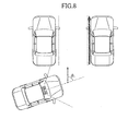
- FIG. 8 schematically shows one example of the orientations of surrounding vehicles and a photographing direction of the stereo camera installed in the occupant vehicle when the occupant vehicle will be parked by moving forward.
- FIG. 9 schematically shows one example of the orientations of surrounding vehicles and a photographing direction of the stereo camera installed in the occupant vehicle during a traffic jam.
- the stereo camera 40-1 for driving assistance is selected as a result of having determined that the vehicle will turn right or left during a normal driving state.
- the stereo camera 40-1 for driving assistance is selected as a result of having determined that the vehicle will turn right or left during a normal driving state.
- no turn signal (winker) is currently being used, there is a possibility that the vehicle is operated for parking or the vehicle has been involved in a traffic jam.
- the image(s) to be used for the recognition it is preferable to use an image(s) obtained from photographing in the forward facing direction taken for the purpose of driving assistance.
- object recognition is carried out first. At this time, it is not necessary to recognize what is an object that appears in the image, i.e., a vehicle, a traffic light, a human being, a building or the like. Blocks having the same parallax value are recognized as an object, and it is determined whether the recognized object stands still. Specifically, a travel distance of the occupant vehicle is measured by the vehicle speed sensor 21, and it is determined whether the recognized object has approached the occupant vehicle by the travel distance based on calculation using the parallax images.
- an image recognition result is useful information for carrying out situation judgment between a state of parking and a state of having been involved in a traffic jam.
- FIG. 8 shows an example of carrying out parking.
- the angle formed between the orientation of the surrounding vehicles and the direction of the optical axis of the stereo camera installed in the occupant vehicle is referred to as ⁇ 1 .
- FIG. 9 shows an example of having been involved in a traffic jam.
- the angle formed between the orientation of the surrounding vehicles and the direction of the optical axis of the stereo camera installed in the occupant vehicle is referred to as ⁇ 2 .
- the orientation of the surrounding vehicles can be obtained from a steering rudder angle or a yaw rate sensor or can be determined from the parallax images.
- the orientation of the vehicle in front of the occupant vehicle is approximately the same as the orientation of the occupant vehicle, except for a case where the road makes a sharp curve.
- ⁇ 2 has a small value.
- ⁇ 1 has a large value. It may be also considered to carry out situation judgment by previously providing a threshold of the relative angle between the front object (vehicle) and the occupant vehicle.
- the situation judgment and image selection part 11 determines whether to carry out driving assistance or parking assistance based on ⁇ (i.e., ⁇ 1 or ⁇ 2 ), and carries out the above-described assistance contents.
- FIG. 10 shows one example of a procedure of determining whether the vehicle will move forward and carry out parking or is in a normal driving state.
- the situation judgment and image selection part 11 determines whether the shift position is in the "drive” position (step S10). In a case in the "drive” position, there is a possibility that the vehicle moves forward and carries out parking.
- the situation judgment and image selection part 11 determines whether the vehicle speed is less than or equal to the threshold (step S20).
- the threshold is, for example, on the order of 10 through 20 [km/h]. In a case where the vehicle speed is less than or equal to the threshold, there is a possibility that the vehicle will carry out parking.
- step S30 the situation judgment and image selection part 11 determines whether the brake frequency is greater than "a" and less than "b" (step S30). In a case where the brake frequency is greater than "a” and less than "b", there is a possibility that the driver is adjusting the vehicle speed to slow down.
- step S30 yes the situation judgment and image selection part 11 then determines whether the direction indicator sensor 24 has detected operation of the direction indicator (step S40). In a case where the direction indicator sensor 24 has detected operation of the direction indicator, there is a possibility that the vehicle is preparing to turn right or left at an intersection or the like.
- the situation judgment and image selection part 11 determines that the vehicle will move forward and carry out parking, and will select the stereo camera(s) for parking assistance (step S50).
- step S60 the situation judgment and image selection part 11 determines to carry out other assistance (step S60).
- the other assistance is driving assistance or door opening/closing assistance, and depending on the conditions, no such assistance may be carried out.
- the preprocessing part 12 processes an image(s) of the stereo camera(s) selected by the situation judgment and image selection part 11 so that the image(s) can be used for calculation by the common correlation calculation part 13.
- Distortion Correction that is required for carrying out distance measurement with a high precision will be described. Distortion directly influences on parallax, and thus the distance measurement result might be very low in precision if correlation calculation were carried out using a photographed image(s) with the distortion kept uncorrected.
- the target measurement distances and field angles of the respective cameras are different, and thus there is a possibility that different lenses are used. Lenses inevitably have distortion, and lenses having different focal lengths and/or field angles (i.e., lenses of different design values) have difference in a manner of being distorted. Further, even the distortion values of lenses that have the same design value mat vary due to manufacturing errors or the like. Thus, distortion correction parameters of the respective monocular cameras are previously stored in the memory 150-2.
- a LUT that has information for converting the pixel values before the correction into those after the correction for all the pixels may be used, or the distortion may be expressed by a polynomial.
- a large storage volume is required for such a LUT, and thus it may be preferable to express the distortion by a polynomial.
- the plural stereo cameras are used. Thus, an enormous storage volume may be required if the LUT data of all of the monocular cameras is stored.
- the quartic polynomial shown in the following formula (1) may be considered.
- This distortion correction formula (1) expresses both distortion that exists in a design stage and distortion that is different for each camera due to manufacturing errors or the like even with the same design values.
- ⁇ x and ⁇ y denote distortion amounts of a certain lens in an x direction and a y direction.
- x and y denote ideal image forming position coordinates.
- f1, f2, ..., fk and g1, g2, ..., gk denote distortion coefficients for a certain temperature.
- the above-described distortion further varies for each monocular camera depending on the temperature.
- the temperature of the inside of the vehicle may become near 80°C.
- the distortion amount variation due to the temperature may be large, and thus, distortion correction concerning the distortion due to the temperature is required for obtaining the distance measurement result with a high precision before the correlation calculation.
- the preprocessing part 11 After the situation judgment and image selection part 11 confirms from the temperature information detected by the temperature sensor 27 that the stereo cameras satisfy the correction possible temperature range, the preprocessing part 11 also obtains the information of the temperature sensor 27.
- the distortion correction parameters are previously stored for the respective monocular cameras corresponding to variations in the temperature.
- the LUT, the polynomial or the like may be considered. However, it can be considered that the above-mentioned polynomial (see the formula (1)) is preferable.
- the following formula (2) may be considered, for example.
- the formula (2) is the same as the above-mentioned formula (1), but the distortion coefficients f and g (i.e., f1, f2, ..., fk and g1, g2, ..., gk) are expressed as functions of the temperature "t".
- the required storage volume can be reduced as a result of, instead of storing the distortion coefficients for the respective monocular cameras at each temperature, thus further expressing the distortion coefficients by the functions of the temperature.
- the correlation calculation part 13 carries out common processing on a pair of sets of image data that have been output from the preprocessing part 12. At this time, information indicating one of the stereo cameras 40-1, 40-2 and 40-3 which has photographed the pair of sets of images that have been input from the preprocessing part 12 is input together with the image data.
- the correlation calculation part 13 carries out stereo matching according to the base-line length, the number of pixels and the search range of the stereo camera that has obtained the image data and so forth and carries out correlation calculation. It is preferable that a memory 150-3 (see FIG. 4 ) previously stores the information of the base-line lengths, the numbers of pixels and the search ranges of the respective stereo cameras. By the correlation calculation, the parallax p is calculated.
- a Sum of Absolute Difference (SAD) method is known.
- SAD Sum of Absolute Difference
- parts in which the same photographing target is photographed are extracted from a pair of sets of stereo image data photographed by any one of the stereo cameras 40-1, 40-2 and 40-3.
- the same points of the photographing target are associated between the pair of sets of stereo image data and shift amounts (parallax) between the associated points are obtained.
- one of the two images is fixed and a pixel block of 3 by 3 or the like, for example, is taken out with a center that is a target pixel from the other image.
- the pixel block is then shifted pixel by pixel with respect to the pixels of the first image and thus the most coincident position will be obtained.
- the most coincident position will be obtained by the following procedure.
- the integrated value of the absolute values of the differences in the luminance values at the pixel block between the two images is obtained as an evaluation value.
- the position of the pixel block at which the evaluation value is minimized is obtained as the most coincident position.
- n the number of pixels by which the pixel block has been thus shifted up to the most coincident position
- s the pixel pitch
- the recognition part 14 carries out object recognition using parallax and a formula by which it is possible to calculate the distance to a target including an offset.
- the vehicle is currently moving in many cases.
- a determination is made to avoid collisions with the surrounding objects in consideration of the information of the vehicle speed sensor 21, the steering rudder angle sensor 22, the shift position sensor 23 and so forth together. Since the stereo camera 40-1 is installed in the occupant vehicle, control may be made to avoid a collision when the distance of a surrounding object from the occupant vehicle has become short without regard to whether the surrounding object stands still or is currently moving with respect to the ground.
- characteristics of targets are previously stored in a memory 150-4 (see FIG. 4 ) as dictionary data.
- a traffic light a stripe pattern of a pedestrian crossing, a temporary stop line, a stop sign, a railroad crossing, a human being, a shape of another vehicle viewed from the back side and/or the like may be cited.
- the driver can recognize an object the distance of which has become short and can become careful thereabout.
- this information may be input to the situation judgment and image selection part 11, and thereby, it is possible to carry out the situation judgment more precisely.
- dictionary data is advantageously not required.
- the result of the recognition may be stored in the memory 150-4, the recognized object may be tracked every several frames, and the speed and the orientation of the object may be determined.
- the absolute speed of the object i.e., whether the object is moving at the speed higher or lower with respect to the ground using the speed information of the occupant vehicle.
- an object that is approaching the vehicle can be recognized and a timing at which opening/closing a door is possible can be determined using the speed of the recognized object and/or the like and can be informed the passenger(s) and/or the driver. Further, in this case, the opening/closing of the door can be controlled based on the recognition result. Further, for example, it is possible to select an image(s) of the stereo camera which is currently photographing an object that has such a moving speed that it is approaching the occupant vehicle earliest.
- the stereo camera 40-1 for parking assistance is also used as at least one of the stereo cameras 40-2 and 40-3 for door opening/closing assistance
- a photographed image(s) is(are) of a wall, a side surface of a stopped vehicle and/or the like in many cases.
- it(them) it is possible to carry out parking assistance.
- What can be obtained from the parallax images is not only a distance to a door or a target (i.e., a wall or a side surface of another vehicle) but also an inclination of the surface, the orientation of the surface and/or the like.
- the direction of installation of the stereo camera with respect to the occupant vehicle may be previously stored in the memory 150-1.
- the driver can again operate the vehicle to carry out parking so as to control the occupant vehicle to be straight with respect to the surrounding wall or the other vehicle.
- the occupant vehicle When the other vehicle has been also turned from the parking position, the occupant vehicle will also be turned and parked in the same way. Thus, it is also possible that before parking, it is previously determined whether the surrounding vehicle has been turned from a white line or the like using the stereo camera for driving assistance.
- the driver may be informed that the vehicle is nearer to one side than the other side in a case where one of the distances to the surrounding walls or the other vehicles on the right side and the left side is greater than or equal to a predetermined value viewed from the driver's seat.
- a preferable distance to a surrounding wall and/or another vehicle may be previously set. Then, when the distance is less than or equal to the set distance, the driver is informed of this matter together with information indicating whether the corresponding side is the left side or the right side. Then the driver can again carry out parking so that the distance required for, for example, a child to ride into or exit the vehicle can be provided on a lateral side.
- the situation judgment and image selection part 11 has selected the stereo cameras 40-2 and 40-3 for door opening/closing assistance, it is possible to calculate an allowable value of a door opening from the distance measurement result calculated from the parallax images and the movable range of the door of the vehicle, the thickness of the door and the width of a human being stored in the memory 150-4. That is, it is determined whether the door can be opened completely, the door can be opened to such a distance that a human being can just pass through without margin, a human being cannot pass through even when the door is opened or the like.
- External parameters that indicate relative distances between the cameras, the orientations of the cameras and so forth are previously determined. However, although the external parameters are adjusted with high precision at a time of shipment of the vehicle, the external parameters may be shifted due to aging or the like. When the external parameters have been thus changed, the parallax calculation precision may be degraded accordingly. Thus, after the stereo camera(s) is(are) selected by the situation judgment and image selection part 11, at a time of the correlation calculation, the amounts by which the external parameters have been thus changed may be preferably reflected in the correlation calculation. The amounts by which the external parameters have been thus changed are calculated by an external parameter change amount calculation part 31 (see FIG. 4 ).
- the above-mentioned recognition results are displayed on the display device 41, and are informed the driver by sound. Further, not only a display and/or sound, but also control of the brake, control of the door's movable range, control of the door lock and/or the like are effective.
- the display and warning control part 15 can warn the driver in various methods such as displaying on the display device 41 how many seconds will be taken before the occupant vehicle will collide with a target, sounding an alarm, displaying a vehicle which is approaching the occupant vehicle in a manner of blinking with a red color and/or the like.
- the driver is also effective to allow the driver to see which camera(s) is(are) currently carrying out distance measurement or which camera(s) is(are) not currently carrying out the distance measurement.
- the state of the distance measurement being carried out by the stereo camera 40-1 may be previously determined as a basic state. Then, a lamp may be lit, sound may be generated and/or a display may be made on the display device 41 when the stereo cameras 40-2 and 40-3 for door opening/closing assistance are selected for carrying out the distance measurement.
- the stereo camera system 100 can precisely determine a situation that requires driving or parking assistance and a situation that requires door opening/closing assistance, and carry out the corresponding assistance. Further, the camera(s) is(are) completely switched, and thus, the driver and/or the passenger(s) can know which camera(s) is(are) currently used for monitoring the surroundings. Conversely, it is possible to instantaneously determine which direction the driver and/or the passenger(s) should pay attention.
- the recognition result(s) can be used to control the door so that the door can be opened only to such a range that the door can be prevented from hitting a surrounding object even without the need for the passenger(s) and/or the driver to pay attention.
- the stereo camera system 100 can recognize the distance and the speed of a surrounding object to determine whether there is an object that is approaching from the periphery and inform the passenger(s) and/or the driver of a timing at which the door will be opened/closed.
- the image processing apparatus (the stereo camera system 100) that uses the stereo cameras, the cost of which apparatus can be reduced.
Landscapes
- Engineering & Computer Science (AREA)
- Physics & Mathematics (AREA)
- General Physics & Mathematics (AREA)
- Theoretical Computer Science (AREA)
- Multimedia (AREA)
- Computer Vision & Pattern Recognition (AREA)
- Signal Processing (AREA)
- Image Analysis (AREA)
- Measurement Of Optical Distance (AREA)
- Traffic Control Systems (AREA)
- Image Processing (AREA)
Applications Claiming Priority (2)
| Application Number | Priority Date | Filing Date | Title |
|---|---|---|---|
| JP2011221995 | 2011-10-06 | ||
| JP2012155413A JP2013093013A (ja) | 2011-10-06 | 2012-07-11 | 画像処理装置、車両 |
Publications (1)
| Publication Number | Publication Date |
|---|---|
| EP2579231A1 true EP2579231A1 (fr) | 2013-04-10 |
Family
ID=47325785
Family Applications (1)
| Application Number | Title | Priority Date | Filing Date |
|---|---|---|---|
| EP12185981.3A Withdrawn EP2579231A1 (fr) | 2011-10-06 | 2012-09-25 | Appareil de traitement d´images pour véhicule |
Country Status (3)
| Country | Link |
|---|---|
| US (1) | US20130088578A1 (fr) |
| EP (1) | EP2579231A1 (fr) |
| JP (1) | JP2013093013A (fr) |
Cited By (14)
| Publication number | Priority date | Publication date | Assignee | Title |
|---|---|---|---|---|
| EP3053809A1 (fr) * | 2015-02-09 | 2016-08-10 | Application Solutions (Electronics and Vision) Limited | Système d'assistance au stationnement |
| EP3139346A1 (fr) * | 2015-09-01 | 2017-03-08 | Autoliv Development AB | Système de vision pour un véhicule automobile et procédé de commande dudit système |
| EP3239945A1 (fr) * | 2016-04-28 | 2017-11-01 | H.P.B Optoelectronic Co., Ltd. | Système de sécurité de véhicule |
| FR3055297A1 (fr) * | 2016-08-24 | 2018-03-02 | Peugeot Citroen Automobiles Sa | Dispositif de controle de roues directrices d'un vehicule a double commande, par priorite d'action d'un volant |
| FR3055298A1 (fr) * | 2016-08-24 | 2018-03-02 | Peugeot Citroen Automobiles Sa | Dispositif de controle du couplage de volants a des roues directrices d'un vehicule a double commande |
| US10099615B2 (en) | 2014-09-29 | 2018-10-16 | Ambarella, Inc. | All-round view monitoring system for a motor vehicle |
| CN109993978A (zh) * | 2017-12-29 | 2019-07-09 | 浙江宇视科技有限公司 | 车辆抓拍方法、装置及门岗系统 |
| US10706589B2 (en) | 2015-12-04 | 2020-07-07 | Veoneer Sweden Ab | Vision system for a motor vehicle and method of controlling a vision system |
| EP3706038A1 (fr) * | 2019-03-07 | 2020-09-09 | MAN Truck & Bus SE | Véhicule automobile doté d'une pluralité de dispositifs capteurs destinés à la détection d'environnement |
| CN111986248A (zh) * | 2020-08-18 | 2020-11-24 | 东软睿驰汽车技术(沈阳)有限公司 | 多目视觉感知方法、装置及自动驾驶汽车 |
| US11180080B2 (en) | 2019-12-13 | 2021-11-23 | Continental Automotive Systems, Inc. | Door opening aid systems and methods |
| US20210362709A1 (en) * | 2018-03-29 | 2021-11-25 | Toyota Jidosha Kabushiki Kaisha | Rear view monitoring device |
| US20230278553A1 (en) * | 2022-03-01 | 2023-09-07 | GM Global Technology Operations LLC | Systems and methods for detecting turn indicator light signals |
| CN119611515A (zh) * | 2024-11-26 | 2025-03-14 | 苏州衡鲁汽车部件有限公司 | 一种线控转向辅助制动方法及装置 |
Families Citing this family (71)
| Publication number | Priority date | Publication date | Assignee | Title |
|---|---|---|---|---|
| US9065955B2 (en) * | 2012-10-15 | 2015-06-23 | Fuji Xerox Co., Ltd. | Power supply control apparatus, image processing apparatus, non-transitory computer readable medium, and power supply control method |
| JP2014115978A (ja) * | 2012-11-19 | 2014-06-26 | Ricoh Co Ltd | 移動物体認識装置及びこれを用いた報知装置及びその移動物体認識装置に用いる移動物体認識用プログラム及び移動物体認識装置を備えた移動体 |
| US9327693B2 (en) * | 2013-04-10 | 2016-05-03 | Magna Electronics Inc. | Rear collision avoidance system for vehicle |
| WO2015004784A1 (fr) * | 2013-07-11 | 2015-01-15 | トヨタ自動車株式会社 | Dispositif d'affichage d'informations de véhicule et procédé d'affichage d'informations de véhicule |
| US9107513B2 (en) * | 2013-07-16 | 2015-08-18 | Amirmasood Asfa | Baby walker system with a braking mechanism for movement control |
| US9509909B2 (en) * | 2013-11-18 | 2016-11-29 | Texas Instruments Incorporated | Method and apparatus for a surround view camera system photometric alignment |
| JP6476831B2 (ja) | 2013-12-26 | 2019-03-06 | 株式会社リコー | 視差演算システム、情報処理装置、情報処理方法及びプログラム |
| ES2972160T3 (es) * | 2014-01-16 | 2024-06-11 | Polestar Performance Ab | Un vehículo adaptado para la conducción autónoma y un método para detectar objetos obstructores |
| JP6528447B2 (ja) | 2014-02-25 | 2019-06-12 | 株式会社リコー | 視差演算システム及び距離測定装置 |
| JP2015202827A (ja) * | 2014-04-16 | 2015-11-16 | 株式会社デンソー | 乗員センサ |
| US9892493B2 (en) | 2014-04-21 | 2018-02-13 | Texas Instruments Incorporated | Method, apparatus and system for performing geometric calibration for surround view camera solution |
| JP2016001170A (ja) * | 2014-05-19 | 2016-01-07 | 株式会社リコー | 処理装置、処理プログラム、及び、処理方法 |
| JP2016001464A (ja) | 2014-05-19 | 2016-01-07 | 株式会社リコー | 処理装置、処理システム、処理プログラム、及び、処理方法 |
| JP5962706B2 (ja) * | 2014-06-04 | 2016-08-03 | トヨタ自動車株式会社 | 運転支援装置 |
| JP5949840B2 (ja) * | 2014-06-19 | 2016-07-13 | トヨタ自動車株式会社 | 駐車支援装置 |
| US20160026881A1 (en) * | 2014-07-22 | 2016-01-28 | Vislab S.R.L. | Lateral obstacle detection apparatus for a motor vehicle, motor vehicle comprising that apparatus and process for detecting lateral obstacles during the travel of a motor vehicle |
| KR101558805B1 (ko) | 2014-09-03 | 2015-10-07 | 현대자동차주식회사 | 스테레오 매칭용 보간 계수 보정 장치 |
| US9712741B2 (en) * | 2014-09-19 | 2017-07-18 | Be Topnotch, Llc | Smart vehicle sun visor |
| US9457642B2 (en) * | 2014-09-19 | 2016-10-04 | Ankit Dilip Kothari | Vehicle sun visor with a multi-functional touch screen with multiple camera views and photo video capability |
| KR101628503B1 (ko) * | 2014-10-27 | 2016-06-08 | 현대자동차주식회사 | 운전자 보조장치 및 그 작동 방법 |
| DE102014018913A1 (de) * | 2014-12-17 | 2016-06-23 | Daimler Ag | Fahrerassistenzeinrichtung für einen Kraftwagen sowie Verfahren zum Betreiben einer solchen |
| JP2016126243A (ja) | 2015-01-07 | 2016-07-11 | 株式会社リコー | カメラ装置 |
| EP3043202B1 (fr) | 2015-01-09 | 2019-07-24 | Ricoh Company, Ltd. | Système de corps mobile |
| JP6558952B2 (ja) * | 2015-05-27 | 2019-08-14 | 京セラ株式会社 | 撮像装置、車両、設置位置判別システム、設置位置判別装置、および設置位置判別方法 |
| EP3306589B1 (fr) * | 2015-06-05 | 2019-01-09 | Nissan Motor Co., Ltd. | Dispositif de détection de feu de circulation et procédé de détection de feu de circulation |
| JP2017024538A (ja) * | 2015-07-22 | 2017-02-02 | 修一 田山 | 自動車接近警告システム |
| US11691619B2 (en) | 2015-08-12 | 2023-07-04 | Hyundai Motor Company | Automatic parking system and automatic parking method |
| US10392009B2 (en) | 2015-08-12 | 2019-08-27 | Hyundai Motor Company | Automatic parking system and automatic parking method |
| CN105882516A (zh) * | 2015-11-13 | 2016-08-24 | 乐卡汽车智能科技(北京)有限公司 | 车辆碰撞预警方法、装置和车辆 |
| KR101619838B1 (ko) * | 2015-12-09 | 2016-05-13 | 공간정보기술 주식회사 | 다수 스테레오 카메라를 이용한 피사체 공간이동 추적 시스템 |
| US20170185763A1 (en) * | 2015-12-29 | 2017-06-29 | Faraday&Future Inc. | Camera-based detection of objects proximate to a vehicle |
| US10776636B2 (en) * | 2015-12-29 | 2020-09-15 | Faraday&Future Inc. | Stereo camera-based detection of objects proximate to a vehicle |
| DE102016102510A1 (de) * | 2016-02-12 | 2017-08-17 | Kiekert Aktiengesellschaft | Verfahren und Vorrichtung zur Beaufschlagung einer Kraftfahrzeugtür im Sinne eines Abbremsens insbesondere zur Kollisionsvermeidung |
| DE102016104730A1 (de) * | 2016-03-15 | 2017-09-21 | Connaught Electronics Ltd. | Verfahren zum Detektieren eines Objekts entlang einer Straße eines Kraftfahrzeugs, Rechenvorrichtung, Fahrerassistenzsystem sowie Kraftfahrzeug |
| US9970227B2 (en) | 2016-06-24 | 2018-05-15 | International Business Machines Corporation | Smart opening system and a method of operating a smart opening system |
| TWI603271B (zh) * | 2016-10-20 | 2017-10-21 | 元智大學 | 自動化電動機車識別與車體瑕疵檢測之方法及其系統 |
| KR101915166B1 (ko) * | 2016-12-30 | 2018-11-06 | 현대자동차주식회사 | 자동 주차 시스템 및 자동 주차 방법 |
| KR101915167B1 (ko) * | 2016-12-30 | 2018-11-06 | 현대자동차주식회사 | 자동 주차 시스템 및 자동 주차 방법 |
| US11393340B2 (en) | 2016-12-30 | 2022-07-19 | Hyundai Motor Company | Automatic parking system and automatic parking method |
| KR101915165B1 (ko) * | 2016-12-30 | 2018-11-06 | 현대자동차주식회사 | 자동 주차 시스템 및 자동 주차 방법 |
| JP6760867B2 (ja) * | 2017-02-20 | 2020-09-23 | 株式会社アルファ | 車両用周辺監視装置 |
| EP3640108B1 (fr) * | 2017-06-15 | 2024-11-06 | Hitachi Astemo, Ltd. | Dispositif de commande de véhicule |
| KR102443051B1 (ko) * | 2017-09-07 | 2022-09-14 | 삼성전자주식회사 | 차량을 보호하기 위한 전자 장치 및 방법 |
| DE102017217074A1 (de) | 2017-09-26 | 2019-03-28 | Volkswagen Aktiengesellschaft | Verfahren, Vorrichtung und computerlesbares Speichermedium mit Instruktionen zum Kennzeichnen einer Ausstiegsseite eines Kraftfahrzeugs |
| US10596958B2 (en) * | 2018-01-30 | 2020-03-24 | Toyota Research Institute, Inc. | Methods and systems for providing alerts of opening doors |
| JP7147259B2 (ja) * | 2018-05-15 | 2022-10-05 | 日産自動車株式会社 | 車載装置、車載装置の制御方法、及び予備動作推定システム |
| JP7134780B2 (ja) * | 2018-08-13 | 2022-09-12 | 日立Astemo株式会社 | ステレオカメラ装置 |
| JP7184591B2 (ja) * | 2018-10-15 | 2022-12-06 | 三菱重工業株式会社 | 車両用画像処理装置、車両用画像処理方法、プログラムおよび記憶媒体 |
| US10339400B1 (en) * | 2018-12-18 | 2019-07-02 | Chongqing Jinkang New Energy Automobile Co., Ltd. | Traffic light detection using multiple cameras |
| JP6946605B2 (ja) * | 2018-12-27 | 2021-10-06 | 三井金属アクト株式会社 | ドア自動開閉システム |
| JP7215228B2 (ja) * | 2019-03-01 | 2023-01-31 | トヨタ自動車株式会社 | 制御装置、制御方法、制御プログラム |
| JP7135977B2 (ja) * | 2019-03-29 | 2022-09-13 | マツダ株式会社 | 車両用演算装置 |
| JP7323326B2 (ja) * | 2019-04-22 | 2023-08-08 | フォルシアクラリオン・エレクトロニクス株式会社 | 駐車支援装置、及び駐車支援装置の制御方法 |
| JP2020190416A (ja) * | 2019-05-17 | 2020-11-26 | アイシン・エィ・ダブリュ株式会社 | 認識システム、認識方法、及び認識プログラム |
| DE102019122632A1 (de) * | 2019-08-22 | 2021-02-25 | Bayerische Motoren Werke Aktiengesellschaft | Anzeigesystem für ein Kraftfahrzeug |
| US11550322B1 (en) | 2019-09-30 | 2023-01-10 | Aurora Operations, Inc. | External environment sensor data prioritization for autonomous vehicle |
| US11526175B1 (en) * | 2019-09-30 | 2022-12-13 | Aurora Operations, Inc. | Sensor data prioritization for autonomous vehicle based on vehicle operation data |
| JP7330926B2 (ja) * | 2020-05-14 | 2023-08-22 | 大成建設株式会社 | 撮影システムおよび遠隔操作システム |
| FR3110753B1 (fr) * | 2020-05-19 | 2022-11-04 | Renault Sas | Procédé de commande d’un système de sortie sécurisée d’un véhicule automobile |
| JP7415860B2 (ja) * | 2020-09-15 | 2024-01-17 | トヨタ自動車株式会社 | 降車支援装置 |
| CN112633096B (zh) * | 2020-12-14 | 2024-08-23 | 深圳云天励飞技术股份有限公司 | 客流的监测方法、装置、电子设备及存储介质 |
| JP7491208B2 (ja) * | 2020-12-22 | 2024-05-28 | トヨタ自動車株式会社 | 降車動作判定装置、車両、降車動作判定法及びプログラム |
| JP7633901B2 (ja) * | 2021-08-24 | 2025-02-20 | 日立Astemo株式会社 | 制御装置 |
| JP7780284B2 (ja) * | 2021-09-21 | 2025-12-04 | 株式会社Subaru | 車外環境認識装置 |
| US12400454B2 (en) * | 2022-03-16 | 2025-08-26 | Honeywell International Inc. | Method and system to analyze spaces for cleaning based on the presence of an individual |
| JP7613406B2 (ja) * | 2022-04-01 | 2025-01-15 | トヨタ自動車株式会社 | 地物検出装置、地物検出方法及び地物検出用コンピュータプログラム |
| US12518426B2 (en) * | 2022-04-14 | 2026-01-06 | Hitachi Astemo, Ltd. | In-vehicle image processing device and calibration method of the same |
| IT202200009593A1 (it) * | 2022-05-10 | 2023-11-10 | Fiat Ricerche | "Veicolo equipaggiato con un sistema per rilevare la distanza di un oggetto antistante il veicolo, sulla base di una comunicazione di tipo V2X con altri veicoli e sulla base di un rilevamento di posizione" |
| JP7816094B2 (ja) * | 2022-11-28 | 2026-02-18 | 株式会社デンソー | 制御装置、リソース管理方法、リソース管理プログラム |
| US12293545B2 (en) * | 2023-01-26 | 2025-05-06 | Ford Global Technologies, Llc | Occupant head position in vehicle |
| CN118506606B (zh) * | 2024-05-22 | 2025-05-13 | 轻松无忧科技(成都)有限公司 | 一种基于图像处理的安全辅助驾驶方法及系统 |
Citations (9)
| Publication number | Priority date | Publication date | Assignee | Title |
|---|---|---|---|---|
| JP2003348575A (ja) | 2002-05-27 | 2003-12-05 | Fuji Heavy Ind Ltd | ステレオ式車外監視装置およびその制御方法 |
| US20050280520A1 (en) * | 2004-06-16 | 2005-12-22 | Denso Corporation | Driving state determining system |
| US20060187304A1 (en) * | 2005-02-18 | 2006-08-24 | Denso Corporation | Device for monitoring the vicinities of a vehicle |
| US20070255480A1 (en) * | 2006-04-21 | 2007-11-01 | Southall John B | Apparatus and method for object detection and tracking and roadway awareness using stereo cameras |
| US20080088707A1 (en) * | 2005-05-10 | 2008-04-17 | Olympus Corporation | Image processing apparatus, image processing method, and computer program product |
| US20090122136A1 (en) * | 2005-07-13 | 2009-05-14 | Toyota Jidosha Kabushiki Kaisha | Object detection device |
| JP2011221995A (ja) | 2006-05-15 | 2011-11-04 | Microsoft Corp | ワイヤレス・ネットワークにおいて発見情報を伝達するメカニズム |
| JP2012155413A (ja) | 2011-01-24 | 2012-08-16 | Nec Corp | ポータルサーバ及びポータルページ表示方法 |
| WO2013035353A1 (fr) * | 2011-09-05 | 2013-03-14 | 三菱電機株式会社 | Appareil de traitement d'image et procédé de traitement d'image |
Family Cites Families (5)
| Publication number | Priority date | Publication date | Assignee | Title |
|---|---|---|---|---|
| US4196940A (en) * | 1972-06-27 | 1980-04-08 | Texas Instruments Incorporated | Differentiator and variable threshold gate circuit for vehicle skid control brake system |
| DE19853344A1 (de) * | 1998-11-19 | 2000-05-25 | Volkswagen Ag | Automatisches Türöffnungssystem |
| US7852462B2 (en) * | 2000-05-08 | 2010-12-14 | Automotive Technologies International, Inc. | Vehicular component control methods based on blind spot monitoring |
| JP2008195263A (ja) * | 2007-02-14 | 2008-08-28 | Denso Corp | 車両用後退支援装置 |
| US8442755B2 (en) * | 2008-09-29 | 2013-05-14 | GM Global Technology Operations LLC | Systems and methods for preventing motor vehicle side doors from coming into contact with obstacles |
-
2012
- 2012-07-11 JP JP2012155413A patent/JP2013093013A/ja active Pending
- 2012-09-25 EP EP12185981.3A patent/EP2579231A1/fr not_active Withdrawn
- 2012-10-02 US US13/633,548 patent/US20130088578A1/en not_active Abandoned
Patent Citations (9)
| Publication number | Priority date | Publication date | Assignee | Title |
|---|---|---|---|---|
| JP2003348575A (ja) | 2002-05-27 | 2003-12-05 | Fuji Heavy Ind Ltd | ステレオ式車外監視装置およびその制御方法 |
| US20050280520A1 (en) * | 2004-06-16 | 2005-12-22 | Denso Corporation | Driving state determining system |
| US20060187304A1 (en) * | 2005-02-18 | 2006-08-24 | Denso Corporation | Device for monitoring the vicinities of a vehicle |
| US20080088707A1 (en) * | 2005-05-10 | 2008-04-17 | Olympus Corporation | Image processing apparatus, image processing method, and computer program product |
| US20090122136A1 (en) * | 2005-07-13 | 2009-05-14 | Toyota Jidosha Kabushiki Kaisha | Object detection device |
| US20070255480A1 (en) * | 2006-04-21 | 2007-11-01 | Southall John B | Apparatus and method for object detection and tracking and roadway awareness using stereo cameras |
| JP2011221995A (ja) | 2006-05-15 | 2011-11-04 | Microsoft Corp | ワイヤレス・ネットワークにおいて発見情報を伝達するメカニズム |
| JP2012155413A (ja) | 2011-01-24 | 2012-08-16 | Nec Corp | ポータルサーバ及びポータルページ表示方法 |
| WO2013035353A1 (fr) * | 2011-09-05 | 2013-03-14 | 三菱電機株式会社 | Appareil de traitement d'image et procédé de traitement d'image |
Cited By (21)
| Publication number | Priority date | Publication date | Assignee | Title |
|---|---|---|---|---|
| US10099615B2 (en) | 2014-09-29 | 2018-10-16 | Ambarella, Inc. | All-round view monitoring system for a motor vehicle |
| WO2016128181A1 (fr) * | 2015-02-09 | 2016-08-18 | Application Solutions (Electronics and Vision) Ltd. | Système d'aide au stationnement |
| EP3053809A1 (fr) * | 2015-02-09 | 2016-08-10 | Application Solutions (Electronics and Vision) Limited | Système d'assistance au stationnement |
| EP3139346A1 (fr) * | 2015-09-01 | 2017-03-08 | Autoliv Development AB | Système de vision pour un véhicule automobile et procédé de commande dudit système |
| WO2017036927A1 (fr) * | 2015-09-01 | 2017-03-09 | Autoliv Development Ab | Système de vision pour un véhicule à moteur et procédé de commande d'un système de vision |
| US10706586B2 (en) | 2015-09-01 | 2020-07-07 | Veoneer Sweden Ab | Vision system for a motor vehicle and method of controlling a vision system |
| CN107924570A (zh) * | 2015-09-01 | 2018-04-17 | 奥托立夫开发公司 | 用于机动车辆的视觉系统和控制视觉系统的方法 |
| US10706589B2 (en) | 2015-12-04 | 2020-07-07 | Veoneer Sweden Ab | Vision system for a motor vehicle and method of controlling a vision system |
| EP3239945A1 (fr) * | 2016-04-28 | 2017-11-01 | H.P.B Optoelectronic Co., Ltd. | Système de sécurité de véhicule |
| FR3055297A1 (fr) * | 2016-08-24 | 2018-03-02 | Peugeot Citroen Automobiles Sa | Dispositif de controle de roues directrices d'un vehicule a double commande, par priorite d'action d'un volant |
| FR3055298A1 (fr) * | 2016-08-24 | 2018-03-02 | Peugeot Citroen Automobiles Sa | Dispositif de controle du couplage de volants a des roues directrices d'un vehicule a double commande |
| CN109993978A (zh) * | 2017-12-29 | 2019-07-09 | 浙江宇视科技有限公司 | 车辆抓拍方法、装置及门岗系统 |
| US20210362709A1 (en) * | 2018-03-29 | 2021-11-25 | Toyota Jidosha Kabushiki Kaisha | Rear view monitoring device |
| US11667284B2 (en) * | 2018-03-29 | 2023-06-06 | Toyota Jidosha Kabushiki Kaisha | Rear view monitoring device |
| EP3706038A1 (fr) * | 2019-03-07 | 2020-09-09 | MAN Truck & Bus SE | Véhicule automobile doté d'une pluralité de dispositifs capteurs destinés à la détection d'environnement |
| US11180080B2 (en) | 2019-12-13 | 2021-11-23 | Continental Automotive Systems, Inc. | Door opening aid systems and methods |
| CN111986248A (zh) * | 2020-08-18 | 2020-11-24 | 东软睿驰汽车技术(沈阳)有限公司 | 多目视觉感知方法、装置及自动驾驶汽车 |
| CN111986248B (zh) * | 2020-08-18 | 2024-02-09 | 东软睿驰汽车技术(沈阳)有限公司 | 多目视觉感知方法、装置及自动驾驶汽车 |
| US20230278553A1 (en) * | 2022-03-01 | 2023-09-07 | GM Global Technology Operations LLC | Systems and methods for detecting turn indicator light signals |
| US11951981B2 (en) * | 2022-03-01 | 2024-04-09 | Gm Global Technology Operations | Systems and methods for detecting turn indicator light signals |
| CN119611515A (zh) * | 2024-11-26 | 2025-03-14 | 苏州衡鲁汽车部件有限公司 | 一种线控转向辅助制动方法及装置 |
Also Published As
| Publication number | Publication date |
|---|---|
| JP2013093013A (ja) | 2013-05-16 |
| US20130088578A1 (en) | 2013-04-11 |
Similar Documents
| Publication | Publication Date | Title |
|---|---|---|
| EP2579231A1 (fr) | Appareil de traitement d´images pour véhicule | |
| US9878665B2 (en) | Active detection and enhanced visualization of upcoming vehicles | |
| JP4420011B2 (ja) | 物体検知装置 | |
| US7158015B2 (en) | Vision-based method and system for automotive parking aid, reversing aid, and pre-collision sensing application | |
| US12420780B2 (en) | Vehicular driving assist system using radar sensors and cameras | |
| EP3139340B1 (fr) | Système et procédé d'amélioration de visibilité | |
| KR20180078986A (ko) | 센서 융합 기반 보행자 탐지 및 보행자 충돌 방지 장치 및 방법 | |
| JP4415856B2 (ja) | 周囲感知システムによって路上車両の前方周囲を検出するための方法 | |
| CN104554008A (zh) | 一种车辆安全换道辅助系统 | |
| EP3190021A1 (fr) | Système et procédé d'avertissement de collision | |
| WO2018143803A1 (fr) | Procédé et système pour alerter un conducteur de camion | |
| CN109987101A (zh) | 车辆的控制装置 | |
| US11256088B2 (en) | Vehicle display device | |
| CN110901536A (zh) | 一种盲区检测报警系统及其工作方法 | |
| RU2542835C1 (ru) | Способ контроля "слепой зоны" боковых зеркал движущегося впереди автомобиля и устройство для его осуществления | |
| JP2004310522A (ja) | 車両用画像処理装置 | |
| US12243451B2 (en) | Apparatus for displaying at least one virtual lane line based on environmental condition and method of controlling same | |
| JP7432198B2 (ja) | 状況認識推定システム及び運転支援システム | |
| KR20180039838A (ko) | 차량 후측방 경보 제어장치 및 방법 | |
| CN215474804U (zh) | 车辆盲区防撞预警装置 | |
| KR20230172054A (ko) | 차량 충돌 방지 시스템 및 이를 구비한 차량 및 충돌 방지 방법 | |
| JPH10115518A (ja) | 距離測定装置およびその装置が用いられた車両 | |
| CN113920734A (zh) | 一种基于logistics模型的变道预警方法 | |
| CN120817176B (zh) | 两轮车及其盲区预警方法 | |
| TWI876714B (zh) | 載具於高速移動狀態下偵測靜止物之方法 |
Legal Events
| Date | Code | Title | Description |
|---|---|---|---|
| PUAI | Public reference made under article 153(3) epc to a published international application that has entered the european phase |
Free format text: ORIGINAL CODE: 0009012 |
|
| 17P | Request for examination filed |
Effective date: 20120925 |
|
| AK | Designated contracting states |
Kind code of ref document: A1 Designated state(s): AL AT BE BG CH CY CZ DE DK EE ES FI FR GB GR HR HU IE IS IT LI LT LU LV MC MK MT NL NO PL PT RO RS SE SI SK SM TR |
|
| AX | Request for extension of the european patent |
Extension state: BA ME |
|
| 17Q | First examination report despatched |
Effective date: 20140703 |
|
| STAA | Information on the status of an ep patent application or granted ep patent |
Free format text: STATUS: THE APPLICATION IS DEEMED TO BE WITHDRAWN |
|
| 18D | Application deemed to be withdrawn |
Effective date: 20160628 |