EP2579912B1 - Dispositif et procédé de circulation de liquides dans l'unité de traitement d'un dispositif de traitement médical, en particulier dans le dialyseur d'un dispositif de dialyse - Google Patents
Dispositif et procédé de circulation de liquides dans l'unité de traitement d'un dispositif de traitement médical, en particulier dans le dialyseur d'un dispositif de dialyse Download PDFInfo
- Publication number
- EP2579912B1 EP2579912B1 EP11732366.7A EP11732366A EP2579912B1 EP 2579912 B1 EP2579912 B1 EP 2579912B1 EP 11732366 A EP11732366 A EP 11732366A EP 2579912 B1 EP2579912 B1 EP 2579912B1
- Authority
- EP
- European Patent Office
- Prior art keywords
- fluid
- balancing chamber
- line
- shut
- balancing
- Prior art date
- Legal status (The legal status is an assumption and is not a legal conclusion. Google has not performed a legal analysis and makes no representation as to the accuracy of the status listed.)
- Active
Links
Images


Classifications
-
- A—HUMAN NECESSITIES
- A61—MEDICAL OR VETERINARY SCIENCE; HYGIENE
- A61M—DEVICES FOR INTRODUCING MEDIA INTO, OR ONTO, THE BODY; DEVICES FOR TRANSDUCING BODY MEDIA OR FOR TAKING MEDIA FROM THE BODY; DEVICES FOR PRODUCING OR ENDING SLEEP OR STUPOR
- A61M1/00—Suction or pumping devices for medical purposes; Devices for carrying-off, for treatment of, or for carrying-over, body-liquids; Drainage systems
- A61M1/14—Dialysis systems; Artificial kidneys; Blood oxygenators ; Reciprocating systems for treatment of body fluids, e.g. single needle systems for hemofiltration or pheresis
- A61M1/16—Dialysis systems; Artificial kidneys; Blood oxygenators ; Reciprocating systems for treatment of body fluids, e.g. single needle systems for hemofiltration or pheresis with membranes
- A61M1/1694—Dialysis systems; Artificial kidneys; Blood oxygenators ; Reciprocating systems for treatment of body fluids, e.g. single needle systems for hemofiltration or pheresis with membranes with recirculating dialysing liquid
-
- A—HUMAN NECESSITIES
- A61—MEDICAL OR VETERINARY SCIENCE; HYGIENE
- A61M—DEVICES FOR INTRODUCING MEDIA INTO, OR ONTO, THE BODY; DEVICES FOR TRANSDUCING BODY MEDIA OR FOR TAKING MEDIA FROM THE BODY; DEVICES FOR PRODUCING OR ENDING SLEEP OR STUPOR
- A61M1/00—Suction or pumping devices for medical purposes; Devices for carrying-off, for treatment of, or for carrying-over, body-liquids; Drainage systems
- A61M1/14—Dialysis systems; Artificial kidneys; Blood oxygenators ; Reciprocating systems for treatment of body fluids, e.g. single needle systems for hemofiltration or pheresis
- A61M1/16—Dialysis systems; Artificial kidneys; Blood oxygenators ; Reciprocating systems for treatment of body fluids, e.g. single needle systems for hemofiltration or pheresis with membranes
- A61M1/1621—Constructional aspects thereof
- A61M1/1635—Constructional aspects thereof with volume chamber balancing devices between used and fresh dialysis fluid
-
- A—HUMAN NECESSITIES
- A61—MEDICAL OR VETERINARY SCIENCE; HYGIENE
- A61M—DEVICES FOR INTRODUCING MEDIA INTO, OR ONTO, THE BODY; DEVICES FOR TRANSDUCING BODY MEDIA OR FOR TAKING MEDIA FROM THE BODY; DEVICES FOR PRODUCING OR ENDING SLEEP OR STUPOR
- A61M1/00—Suction or pumping devices for medical purposes; Devices for carrying-off, for treatment of, or for carrying-over, body-liquids; Drainage systems
- A61M1/14—Dialysis systems; Artificial kidneys; Blood oxygenators ; Reciprocating systems for treatment of body fluids, e.g. single needle systems for hemofiltration or pheresis
- A61M1/16—Dialysis systems; Artificial kidneys; Blood oxygenators ; Reciprocating systems for treatment of body fluids, e.g. single needle systems for hemofiltration or pheresis with membranes
- A61M1/1621—Constructional aspects thereof
- A61M1/165—Constructional aspects thereof with a dialyser bypass on the dialysis fluid line
-
- A—HUMAN NECESSITIES
- A61—MEDICAL OR VETERINARY SCIENCE; HYGIENE
- A61M—DEVICES FOR INTRODUCING MEDIA INTO, OR ONTO, THE BODY; DEVICES FOR TRANSDUCING BODY MEDIA OR FOR TAKING MEDIA FROM THE BODY; DEVICES FOR PRODUCING OR ENDING SLEEP OR STUPOR
- A61M1/00—Suction or pumping devices for medical purposes; Devices for carrying-off, for treatment of, or for carrying-over, body-liquids; Drainage systems
- A61M1/36—Other treatment of blood in a by-pass of the natural circulatory system, e.g. temperature adaptation, irradiation ; Extra-corporeal blood circuits
- A61M1/3621—Extra-corporeal blood circuits
- A61M1/3624—Level detectors; Level control
-
- Y—GENERAL TAGGING OF NEW TECHNOLOGICAL DEVELOPMENTS; GENERAL TAGGING OF CROSS-SECTIONAL TECHNOLOGIES SPANNING OVER SEVERAL SECTIONS OF THE IPC; TECHNICAL SUBJECTS COVERED BY FORMER USPC CROSS-REFERENCE ART COLLECTIONS [XRACs] AND DIGESTS
- Y10—TECHNICAL SUBJECTS COVERED BY FORMER USPC
- Y10T—TECHNICAL SUBJECTS COVERED BY FORMER US CLASSIFICATION
- Y10T137/00—Fluid handling
- Y10T137/0318—Processes
- Y10T137/0324—With control of flow by a condition or characteristic of a fluid
-
- Y—GENERAL TAGGING OF NEW TECHNOLOGICAL DEVELOPMENTS; GENERAL TAGGING OF CROSS-SECTIONAL TECHNOLOGIES SPANNING OVER SEVERAL SECTIONS OF THE IPC; TECHNICAL SUBJECTS COVERED BY FORMER USPC CROSS-REFERENCE ART COLLECTIONS [XRACs] AND DIGESTS
- Y10—TECHNICAL SUBJECTS COVERED BY FORMER USPC
- Y10T—TECHNICAL SUBJECTS COVERED BY FORMER US CLASSIFICATION
- Y10T137/00—Fluid handling
- Y10T137/2496—Self-proportioning or correlating systems
- Y10T137/2559—Self-controlled branched flow systems
- Y10T137/2574—Bypass or relief controlled by main line fluid condition
Definitions
- the invention relates to a device for conveying liquids into the treatment unit of a medical treatment device, in particular into the dialyzer of a dialysis machine. Moreover, the invention relates to an extracorporeal blood treatment apparatus, in particular a dialysis apparatus, which has a device for conveying liquids into the treatment unit, in particular the dialyzer, the blood treatment apparatus, in particular the dialysis apparatus.
- the known treatment devices include, for example, the blood treatment devices.
- the blood treatment unit is a dialyzer or filter which is separated by a semipermeable membrane into a blood chamber and a dialysis fluid chamber.
- the blood flows in an extracorporeal blood circulation through the blood chamber while the dialysis fluid flows in a dialysis fluid circuit through the dialysis fluid chamber of the dialyzer.
- the prior art blood treatment methods and devices require the need to accurately account for the fluid withdrawn from the patient and the fluid being delivered to the patient throughout the treatment period.
- the prior art includes gravimetric and volumetric balancers.
- a hemodiafiltration device with volumetric balancing is known, for example, from US Pat DE 26 34 238 A1 known.
- the balancing device of the known hemodiafiltration device has a volume-rigid hollow body, which is divided by a movable partition into two chambers. Each chamber has an inlet and an outlet at which supply and discharge lines for fresh or spent dialysis fluid are arranged, wherein a shut-off device is connected in each line.
- pumps for the promotion of fresh and spent dialysis fluid and a control unit are provided, which allows a reciprocal filling of the two chambers.
- a balancing unit with two balancing chambers is for example from the DE 28 38 414 known.
- the dialysis fluid flow is typically 500 ml / min, but may be up to 1000 ml / min, depending on the particular treatment situation. With a dialysis duration of 4 hours, this means a dialysis fluid need, which is typically between 120 1, depending on the particular treatment situation but can also be over 200 1.
- RO water dialysate from concentrates and pure water
- Dialysis fluid is then provided to the machine via containers, such as canisters or bags.
- a blood treatment device with a recirculation circuit is for example from US 5,685,988 known. However, the recirculation of dialysis fluid should only serve to determine blood treatment parameters.
- a dialysis apparatus which has a balancing unit with two balancing chambers, which are each divided into two chambers. Inlets and outlets of the balancing chambers can be closed with valves.
- Fresh dialysis fluid flows via a line from the balancing unit into a dialyzer and flows out of the dialyzer via the line back to the balancing unit.
- the fresh dialysis fluid is provided in bags and the spent dialysis fluid flows into a drain.
- the known dialysis apparatus provides as a bypass line a conduction path which passes through a filter. While dialysis fluid flows from the balancing unit to the dialyzer and from the dialyzer to the balancing unit, part of the dialysis fluid is pumped through the filter several times by a pump.
- a device for controlling the removal of fluid in hemodialysis with which the supply line leading to the dialyzer is connected to the outgoing from the dialyzer drain line.
- the device In the recirculation circuit, the device has only one pump, which is arranged in the drain line. Therefore, the expert can give no indication of the arrangement of two pumps in the supply line.
- the DE 299 02 953 proposes to flush a filter arranged in the dialysis fluid circuit via a bypass line.
- the DE 42 39 937 A1 describes a method for checking the functionality of a partial device of a hemodialysis machine, wherein in the dialysis fluid system, a bypass line bypassing the dialyzer is provided. To convey the dialysis fluid, only one pump is provided in the dialysis fluid system.
- the EP 2 005 982 A1 describes a dialysis machine having a measuring unit.
- the dialysis apparatus has a recirculation circuit which comprises an inlet and outlet line in which valves are arranged in order to interrupt the inflow or outflow into the measuring unit.
- the known dialysis apparatus provides for the recirculation of dialysis fluid only for measurement purposes.
- the invention has for its object to provide a device for conveying liquids in the treatment unit of a medical treatment device, in particular in the dialyzer of a dialysis machine, with which it is possible to reduce the need for dialysis.
- the device according to the invention is based on the fact that the liquid with which the treatment unit is supplied circulates in a fluid circuit enclosing the treatment unit.
- a balancing unit which may basically have one or two balancing chambers.
- the device according to the invention is characterized in that the balancing chamber of the balancing unit, or the two balancing chambers of the balancing unit, can be integrated into the fluid circuit enclosing the treatment unit.
- This makes it possible to continuously supply fresh liquid to the liquid circuit or to remove used liquid from the liquid circuit.
- the supply and removal of fresh or spent fluid can be carried out at a different flow rate, as with the flow rate at which the liquid circulates in the fluid circuit via the treatment unit. Consequently, a "liquid” sets in the liquid circuit which, depending on the ratio of the flow rates, lies in the concentration between a "fresh liquid” and a "spent liquid".
- the blood circulation unit, in particular the dialyzer, enclosing liquid circuit can be withdrawn regardless of the supply or discharge of fresh or spent liquid and liquid (ultrafiltrate).
- the means for conveying liquid have two pumps, which are arranged in the discharge line leading from the balance chamber to the blood treatment unit. Of these two pumps, one pump is disposed in the portion of this drainage conduit leading to the point where one port of the bypass is connected to the drainage conduit while the other pump is located in the portion of this drainage conduit which is from the attachment point going off the bypass.
- the flow rates of these two pumps in the drain line provide the flow rate at which fresh liquid is fed to the liquid loop, or spent liquid is removed from the liquid loop.
- the flow rate at which the liquid circulates through the treatment unit in the fluid circuit is greater than the flow rate at which fluid is supplied to or removed from the fluid circuit.
- the device according to the invention has a bypass which leads the discharge line leading from the balancing chamber to the treatment unit with that of the Treatment unit to the balance chamber leading inflow line connects.
- the bypass allows not only a continuous supply of fresh fluid into the fluid circuit enclosing the treatment unit, but also the maintenance of a fluid flow through the blood treatment unit when the balance chamber of the balancing unit is filled with fresh fluid with rejection of spent fluid. If a balancing unit with two reciprocating balancing chambers is used, however, this advantage does not come into play.
- a particularly preferred embodiment of the invention therefore provides a balancing unit with only one balancing chamber.
- the bypass ensures that the liquid flow through the blood treatment unit does not break off when the balance chamber is switched over. This results in a simplified construction of the balancing unit.
- the means for conveying liquid into and out of the balance chamber and the means for interrupting the inflow of liquid into the balance chamber or the outflow of liquid from the balance chamber may be formed differently.
- To convey liquid it is preferable to use the known occluding pumps in which hose lines can be inserted.
- To interrupt the inflow or outflow of liquid preferably serve the known electromagnetically or pneumatically actuated shut-off devices which are arranged in the lines.
- a control unit controls the means for conveying liquid and the means for interrupting the inflow or outflow of liquid. Since occluding pumps at standstill disconnect the tubing, the occluding pumps can also replace shut-off valves.
- the means for conveying liquid to a further pump which is arranged in the leading from the liquid source to the balance chamber inlet pipe.
- the means for interrupting the inflow and / or outflow of liquid comprise a first obturator which is in the of a second obturator, which is arranged in the outgoing from the balance chamber and leading to the outflow second drain line, a third obturator, in the outgoing from the balance chamber and leading to the blood treatment unit second drain line is arranged, and a fourth obturator, which is arranged in the leading from the treatment unit to the balancing chamber second inflow line. All shut-off devices are controlled by the control unit.
- the control unit is formed in the particularly preferred embodiment such that in a first cycle of a first cycle of successive working cycles, the first and second shut-off and the third and fourth shut-off are closed, the first and third pump are in operation.
- the balance chamber is filled with fresh liquid, with rejection of spent liquid.
- the liquid flow through the treatment unit is not interrupted.
- the first power stroke is followed by a second power stroke in which the first and second shut-off elements are closed and the third and fourth shut-off devices are opened, with the second and third pumps in operation.
- the liquid circulates in the fluid circuit enclosing the treatment unit. It may, but does not necessarily, fresh liquid supplied to the liquid circuit or be discharged from the liquid circuit.
- Another preferred embodiment provides for the integration of a further obturator in the bypass.
- This obturator is used to better fill and vent the system before performing the treatment.
- the obturator in the bypass and the circulation in the fluid circuit can be interrupted.
- Fig.1 shows in a highly simplified schematic representation of the essential components of the hemodialysis device.
- the device for supplying the dialyzer with dialysis fluid is part of the dialysis machine.
- the dialysis apparatus has a dialyzer 1, which is subdivided by a semipermeable membrane, not shown, into a blood chamber and dialysis fluid chamber, not shown. From the patient leads a blood supply line 2, in which a blood pump 3 is connected, to an inlet 1A of the blood chamber of the dialyzer 1, while from an outlet 1B of the blood chamber of the dialyzer 1 a Blood drainage line 4 goes off, leading to the patient.
- a blood supply line 2 in which a blood pump 3 is connected, to an inlet 1A of the blood chamber of the dialyzer 1, while from an outlet 1B of the blood chamber of the dialyzer 1 a Blood drainage line 4 goes off, leading to the patient.
- the blood of the patient in the extracorporeal blood circulation I flows through the blood chamber of the dialyzer 1.
- the dialyzer 1 is supplied with dialysis fluid which flows through the dialysis fluid chamber of the dialyzer 1.
- the device for conveying the dialysis fluid into the dialyzer 1 will be described below.
- a balancing unit 5 For balancing fresh against spent dialysis fluid is a balancing unit 5, which has only one balance chamber 6 in the present embodiment.
- the balancing chamber 6 has a first inlet 6A at the bottom and a first outlet 6B at the top and a second inlet 6C at the bottom and a second outlet 6D at the top.
- the dialysis fluid is provided in a dialysis fluid source 7, which may be a canister or a bag.
- a dialysis fluid source 7 which may be a canister or a bag.
- a first supply line 8 which leads to the first inlet 6A of the balance chamber 6.
- a first drain line 9 goes off, which leads to a drain or drain 32.
- a blood pump 10 in particular an occluding pump, connected, which promotes fresh dialysis fluid from the Dialysierckenkeitsetti 7 in the balance chamber 6.
- a second outflow line 11 leads, which leads to the inlet 1C of the dialysis fluid chamber of the dialyzer 1.
- a second inflow line 12 which leads to the second inlet 6C of the balancing chamber 6, departs.
- the inflow and outflow lines 8, 9, 11, 12 are hose lines.
- the second outflow line 11 has a first section 11A and a second section 11B in the flow direction, while the second inflow line 12 has a first section 12A and a second section 12B in the flow direction.
- the second outflow line 11 and the second inflow line 12 are connected via a bypass 13.
- the bypass 13 is a pipe having the one end at the connection point 11C between the first portion 11A and the second portion 11B of the second drain pipe 11 and at the other end at the connection point 12C between the first portion 12A and the second portion 12B of the second inflow line 12 is connected.
- a fluid circuit II is created, which includes the dialysis fluid chamber of the dialyzer 1.
- the fluid circuit II comprises the bypass line 13, the second section 11B of the second outflow line 11, the dialysis fluid chamber of the dialyzer 1 and the first section 12A of the second supply line 12.
- a second pump 14 and in the second portion 11 B of the second drain line 11 a third pump 15 is connected.
- an ultrafiltrate line 16 is discharged, into which a fourth pump 17 is connected, with which liquid (ultrafiltrate) liquid can be withdrawn from the liquid circuit II.
- the four pumps 10, 14, 15, 17 are connected via control lines 10 ', 14', 15 ', 17' to a control unit 18.
- the control unit 18 in the present example is part of the central control unit of the dialysis machine.
- the central control unit 18 of the dialysis machine is also connected to the blood pump 3 via a control line 3 '.
- a first obturator 19 is connected between the first pump 10 and the balance chamber 6, while in the first outflow line 9, a second obturator 20 is connected.
- a third obturator 21 is connected between the balance chamber 6 and the second pump 14, while in the second inflow line 12 between the connection point 12C and the balancing chamber 6, a third shut-off valve 22 is connected.
- the shut-off elements 19, 20, 21, 22 are electromagnetically actuated hose clamps, which are connected to the central control unit 18 via control lines 19 ', 20', 21 ', 22'.
- the central control unit 18 controls the pumps 10, 14, 15 as follows.
- the dialysis machine is operated in successive cycles, each comprising two work cycles.
- Fig. 2 shows the first work cycle and Fig. 2 the second working cycle of a work cycle.
- the first power stroke comprises the filling of the balancing chamber 6, while dialyzing fluid flows through the dialyzer 1.
- the central control unit 18 opens the first and second obturators 19, 20 and closes the third and fourth obturators 21, 22. In this case, the control unit 18 sets the first pump 10 and the third pump 15 in operation.
- the second pump 14 is stopped. Since the second occluding pump 14 is stopped, the third obturator 21 may also be open.
- the first pump 10 conveys fresh dialysis fluid from the dialysis fluid source 7 into the balancing chamber 6, which has been filled with spent dialysis fluid in the second working cycle of the preceding working cycle. While the balance chamber 6 is filled with fresh dialysis fluid, the used dialysis fluid is discharged via the first drain line 9 into the drain 32. The first pump 10 runs until the used in the balance chamber 6 spent dialysis fluid is completely replaced by fresh dialysis fluid. During filling of the balance chamber 6 with fresh dialysis fluid, the liquid flow through the dialyzer 1 is not interrupted.
- the third pump 15 conveys the dialysis fluid in the fluid circuit II, which includes the second section 11 B of the second outflow line 11, the dialyzer 1, the first section 12 A of the second inflow line 12 and the bypass line 13.
- the balancing chamber 6 should be filled with fresh dialysis fluid as quickly as possible so that the dialysis fluid only circulates in the fluid circuit for a short period of time ( Fig. 1A ).
- the central control unit 18 closes the first and second shut-off elements 19, 20 and opens the third and fourth shut-off elements 21, 22. Furthermore, the control unit 18 stops the first pump 10 and sets the second pump 14 into operation. Consequently, run the second and third pump 14, 15. The control unit 18 is for the second pump 14 before a smaller delivery rate than for the third pump 15. Consequently flows in the fluid circuit II dialysis fluid at a flow rate corresponding to the difference of the delivery rates of the third and second pump 15, 14. This delivery rate QD almost can be relatively high.
- the liquid circuit II While dialysis fluid circulates in the fluid circuit II through the dialyzer 1, the liquid circuit II is constantly fed fresh dialysis fluid and withdrawn used dialysis liquid the fluid circuit 12.
- the fresh dialysis fluid is supplied to the fluid circuit II with the delivery rate predetermined by the second pump 14 via the first section 11A of the second outflow line 11, which is connected to the second outlet 6D of the balancing chamber 6.
- the second section 12B of the second inflow line 12 which is connected to the second inlet 6C of the balance chamber 6, used dialysis fluid is withdrawn from the fluid circuit II.
- the dialysis device also allows liquid to escape from the liquid II (ultrafiltrate).
- the control unit 18 starts the ultrafiltration pump 17.
- fresh dialysis fluid can be supplied continuously in a relatively short or a relatively long period of time and the desired ratio between fresh and spent dialysis fluid in the fluid circuit II can be set.
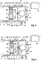
- Fig. 3 shows a second embodiment of the dialysis machine, which differs from that with reference to the Fig. 1 and 2 described embodiment only differs in that in the bypass line 13, a fifth obturator 23 is connected, which is also actuated by the central control unit 18.
- the corresponding parts are therefore provided with the same reference numerals.
- the obturator 23 in the bypass line 13 is basically open during operation of the dialysis device.
- the obturator 23 may also for Interruption of the circulation of the dialysis fluid in the fluid circuit II are closed.
- the obturator 23 is closed in the bypass line 13, so that the liquid flow is interrupted by the bypass line.
- the second obturator 20 is closed so that liquid can not get into the drain 32.
- the liquid is supplied to the balance chamber 6 via the first inflow line 8 while the pump 10 is running. With running pumps 14 and 15, the liquid can flow through the second drain line 11, the dialyzer 1 and the second inflow line 12.
- a vent valve 33 is provided at the top of the balance chamber 6, which in Fig. 3 is shown only in an approximate way.
- Fig. 4 shows an alternative embodiment of the dialysis machine of Fig. 3
- the embodiment of Fig. 4 differs from the embodiment of Fig. 3 only by the leadership of the second drain line 11 and the second inflow line 12 and the length of the bypass line 13.
- the corresponding parts are again provided with the same reference numerals.
- the second outflow and inflow line 11, 12 are brought directly to the connections of the obturator 23, so that the volume of the bypass 13 can be reduced to a minimum.
- the inventive device for supplying the dialyzer with dialysis fluid has the advantage that can be dispensed with a balancing unit with two balancing chambers. Even with a balancing unit which has only one balance chamber, a continuous flow of dialysis fluid through the dialyzer can be maintained during the balancing of fresh versus used dialysis fluid.
- Fig. 5 shows the sake of completeness, a dialysis device with two parallel-connected balancing chambers 6A, 6B, which are operated alternately.
- the embodiment of Fig. 5 differs from the embodiment of Fig. 1 and FIG. 2 in that the second balancing chamber 6B is connected in parallel with the associated inlet and outlet lines 24, 25, 26, 27, into which respective shut-off elements 28, 29, 30, 31 are connected.
- the balancing unit 6 with two balancing chambers 6A, 6B is operated in a known manner, such as in the DE 28 38 414 is described.
- Fig. 6 shows a further embodiment, which differs from the embodiment of Fig. 4 only differs in that the balance chamber 6 is divided by a flexible partition 6G in a first chamber half 6E and a second chamber half 6F.
- the first inlet 6A and the second outlet 6D communicate with the first chamber half 6E
- the second inlet 6C and the first outlet 6B communicate with the second chamber half 6F.
- Both chamber halves 6E and 6F of the balance chamber 6 are alternately filled in this embodiment with fresh and used dialysis fluid.
- the corresponding parts are again provided with the same reference numerals.
- the fluid circuit II allows the maintenance of the flow of dialysis fluid through the dialyzer 1 during filling of the balance chamber 6 with fresh dialysis fluid. If the respective chamber half 6E or 6F is filled with fresh dialysis fluid, the used dialysis fluid is displaced from the respective other chamber half 6F or 6E.
Landscapes
- Health & Medical Sciences (AREA)
- Heart & Thoracic Surgery (AREA)
- Urology & Nephrology (AREA)
- Vascular Medicine (AREA)
- Hematology (AREA)
- Engineering & Computer Science (AREA)
- Anesthesiology (AREA)
- Biomedical Technology (AREA)
- Life Sciences & Earth Sciences (AREA)
- Animal Behavior & Ethology (AREA)
- General Health & Medical Sciences (AREA)
- Public Health (AREA)
- Veterinary Medicine (AREA)
- Emergency Medicine (AREA)
- Cardiology (AREA)
- External Artificial Organs (AREA)
Claims (11)
- Dispositif pour le transport de fluides dans l'unité de traitement d'un dispositif de traitement médical comportant
une unité d'équilibrage (5) qui présente au moins une chambre d'équilibrage (6),
une première conduite d'admission (8) conduisant à la chambre d'équilibrage pour l'acheminement de fluide d'une source de fluide (7) dans la chambre d'équilibrage et une première conduite d'évacuation (9) partant de la chambre d'équilibrage pour l'évacuation de fluide de la chambre d'équilibrage en une opération (32),
une deuxième conduite d'évacuation (11) partant de la chambre d'équilibrage pour l'évacuation de fluide de la chambre d'équilibrage dans une unité de traitement (1) et une deuxième chambre d'admission conduisant à la chambre d'équilibrage pour l'acheminement de fluide de l'unité de traitement dans la chambre d'équilibrage,
des moyens (10, 14, 15) pour le transport d'un fluide dans et/ou hors de la chambre d'équilibrage et des moyens (19, 20, 21, 22) pour interrompre l'admission de fluide dans la chambre d'équilibrage et/ou l'évacuation de fluide de la chambre d'équilibrage,
une unité de commande (18) pour commander les moyens (10, 14, 15) pour le transport d'un fluide et des moyens (19, 20, 21, 22) pour interrompre l'admission et/ou l'évacuation de fluide,
une dérivation (13) reliant la deuxième conduite d'évacuation (11) à la deuxième conduite d'admission (12), qui est conçue de telle sorte qu'un circuit de fluide (II) incluant l'unité de traitement (1) est créé en contournant complètement ou partiellement la chambre d'équilibrage (6), dans lequel
la deuxième conduite d'évacuation (11) présente un premier et un deuxième segment (11A, 11B) dans une direction d'écoulement et la deuxième conduite d'admission (12) présente un premier et un deuxième segment (12A, 12B) dans une direction d'écoulement, et l'un raccordement de la dérivation (13) est raccordé au point de liaison (11C) entre le premier et le deuxième segment de la deuxième conduite d'évacuation et l'autre raccordement de la dérivation est raccordé au point de liaison (12C) entre le premier et le deuxième segment de la deuxième conduite d'admission, et
caractérisé en ce que
les moyens pour le transport de fluide présentent une première pompe (14) qui est agencée dans le premier segment (11A) de la deuxième conduite d'évacuation (11) et une deuxième pompe (15) qui est agencée dans le deuxième segment (11B) de la deuxième conduite d'évacuation (11). - Dispositif selon la revendication 1, caractérisé en ce que les moyens (10, 14, 15) pour le transport de fluide et les moyens (19, 20, 21, 22) pour l'interruption de l'admission et/ou de l'évacuation de fluide sont conçus de telle sorte qu'un courant de fluide peut être réglé à un débit prédéterminé dans le circuit de fluide (II) incluant l'unité de traitement (1).
- Dispositif selon la revendication 2, caractérisé en ce que l'unité de commande (18) est conçue de telle sorte que
dans un premier temps de travail d'un premier cycle de travail de cycles de travail consécutifs, la chambre d'équilibrage (6) est remplie par la première conduite d'admission (8) avec un fluide de la source de fluide (7) en rejetant du fluide de la chambre d'équilibrage par la première conduite d'évacuation (9) dans l'opération (32), dans lequel du fluide circule en contournant complètement la chambre d'équilibrage dans le circuit de fluide (II) incluant l'unité de traitement, et
dans un deuxième temps de travail des cycles de travail consécutifs, un fluide est évacué de la chambre d'équilibrage (6) par la deuxième conduite d'évacuation (11) et du liquide est acheminé par la deuxième conduite d'admission (12) de la chambre d'équilibrage, dans lequel du fluide circule dans le circuit de fluide incluant l'unité de traitement. - Dispositif selon l'une des revendications 1 à 3, caractérisé en ce que les moyens pour le transport de fluide présentent une troisième pompe (10) dans laquelle la première conduite d'admission (8) est agencée.
- Dispositif selon l'une des revendications 1 à 4, caractérisé en ce que les moyens pour interrompre l'admission et/ou l'évacuation de fluide présentent :un premier organe de blocage (19) agencé dans la première conduite d'admission (8),un deuxième organe de blocage (20) agencé dans la première conduite d'évacuation (9),un troisième organe de blocage (21) agencé dans la deuxième conduite d'évacuation (11),un quatrième organe de blocage (22) agencé dans la deuxième conduite d'admission (12).
- Dispositif selon l'une des revendications 1 à 5, caractérisé en ce que les moyens pour le transport de fluide et les moyens pour l'interruption de l'admission et/ou de l'évacuation de fluide présentent un cinquième organe de blocage (23) qui est agencé dans la dérivation (13).
- Dispositif selon la revendication 5 ou 6, caractérisé en ce que l'unité de commande (18) est conçue de telle sorte que
dans un premier temps de travail d'un premier cycle de travail de cycles de travail consécutifs, les premier et deuxième organes de blocage (19, 20) sont ouverts et les troisième et quatrième organes de blocage (21, 22) sont fermés, dans lequel les deuxième et troisième pompes (15, 10) fonctionnent, et
dans un deuxième temps de travail des cycles de travail consécutifs, les premier et deuxième organes de blocage (19, 20) sont fermés et les troisième et quatrième organes de blocage (21, 22) sont ouverts, dans lequel les première et deuxième pompes (15, 10) sont en marche. - Dispositif selon la revendication 7, caractérisé en ce que l'unité de commande (18) est conçue de telle sorte que dans le deuxième temps de travail, les première et deuxième pompes (14, 15) sont actionnées selon différents régimes.
- Dispositif selon la revendication 7 ou 8, caractérisé en ce que l'unité de commande (18) est conçue de telle sorte que la deuxième pompe (15) est actionnée dans le deuxième temps de travail à un régime qui est supérieur au régime de la première pompe (14).
- Dispositif de traitement extracorporel du sang comportant un dispositif selon l'une des revendications 1 à 9.
- Dispositif de traitement extracorporel du sang selon la revendication 10, caractérisé en ce que le dispositif de traitement du sang est un dispositif de dialyse, dans lequel l'unité de traitement du sang est un dialyseur (1).
Applications Claiming Priority (2)
| Application Number | Priority Date | Filing Date | Title |
|---|---|---|---|
| DE201010023635 DE102010023635A1 (de) | 2010-06-14 | 2010-06-14 | Vorrichtung und Verfahren zum Fördern von Flüssigkeiten in die Behandlungseinheit einer medizinischen Behandlungsvorrichtung, insbesondere in den Dialysator einer Dialysevorrichtung |
| PCT/EP2011/002915 WO2011157396A1 (fr) | 2010-06-14 | 2011-06-14 | Dispositif et procédé de circulation de liquides dans l'unité de traitement d'un dispositif de traitement médical, en particulier dans le dialyseur d'un dispositif de dialyse |
Publications (2)
| Publication Number | Publication Date |
|---|---|
| EP2579912A1 EP2579912A1 (fr) | 2013-04-17 |
| EP2579912B1 true EP2579912B1 (fr) | 2017-01-04 |
Family
ID=44628496
Family Applications (1)
| Application Number | Title | Priority Date | Filing Date |
|---|---|---|---|
| EP11732366.7A Active EP2579912B1 (fr) | 2010-06-14 | 2011-06-14 | Dispositif et procédé de circulation de liquides dans l'unité de traitement d'un dispositif de traitement médical, en particulier dans le dialyseur d'un dispositif de dialyse |
Country Status (7)
| Country | Link |
|---|---|
| US (1) | US9603987B2 (fr) |
| EP (1) | EP2579912B1 (fr) |
| JP (1) | JP5778265B2 (fr) |
| CN (1) | CN102985121B (fr) |
| BR (1) | BR112012032035B1 (fr) |
| DE (1) | DE102010023635A1 (fr) |
| WO (1) | WO2011157396A1 (fr) |
Families Citing this family (30)
| Publication number | Priority date | Publication date | Assignee | Title |
|---|---|---|---|---|
| US10089443B2 (en) | 2012-05-15 | 2018-10-02 | Baxter International Inc. | Home medical device systems and methods for therapy prescription and tracking, servicing and inventory |
| CN103889481B (zh) | 2011-08-02 | 2016-03-09 | 美敦力公司 | 带有具有可控的顺应性容积的流动路径的血液透析系统 |
| ES2534477T5 (es) * | 2012-05-09 | 2018-07-20 | D_Med Consulting Ag | Procedimiento para la cebadura de un dispositivo de hemodiálisis |
| US9713666B2 (en) | 2013-01-09 | 2017-07-25 | Medtronic, Inc. | Recirculating dialysate fluid circuit for blood measurement |
| US11154648B2 (en) | 2013-01-09 | 2021-10-26 | Medtronic, Inc. | Fluid circuits for sorbent cartridge with sensors |
| US10010663B2 (en) | 2013-02-01 | 2018-07-03 | Medtronic, Inc. | Fluid circuit for delivery of renal replacement therapies |
| US10850016B2 (en) | 2013-02-01 | 2020-12-01 | Medtronic, Inc. | Modular fluid therapy system having jumpered flow paths and systems and methods for cleaning and disinfection |
| US9623164B2 (en) | 2013-02-01 | 2017-04-18 | Medtronic, Inc. | Systems and methods for multifunctional volumetric fluid control |
| DE102013019356A1 (de) | 2013-11-19 | 2015-06-03 | Fresenius Medical Care Deutschland Gmbh | Vorrichtung und Verfahren zum Bilanzieren von Flüssigkeiten für eine extrakorporale Blutbehandlungsvorrichtung |
| US10537875B2 (en) | 2013-11-26 | 2020-01-21 | Medtronic, Inc. | Precision recharging of sorbent materials using patient and session data |
| US9884145B2 (en) | 2013-11-26 | 2018-02-06 | Medtronic, Inc. | Parallel modules for in-line recharging of sorbents using alternate duty cycles |
| DE102013021012A1 (de) | 2013-12-13 | 2015-06-18 | Fresenius Medical Care Deutschland Gmbh | Vorrichtung zur extrakorporalen Blutbehandlung |
| DE102014003619A1 (de) * | 2014-03-13 | 2015-09-17 | Fresenius Medical Care Deutschland Gmbh | Vorrichtung und Verfahren zum Bilanzieren zwischen einem Zufluss und einem Abfluss aus einer medizinischen Behandlungsvorrichtung |
| EP3160535B1 (fr) | 2014-06-24 | 2024-10-02 | Mozarc Medical US LLC | Ensemble de régénération de dialysat modulaire |
| US10357757B2 (en) | 2014-06-24 | 2019-07-23 | Medtronic, Inc. | Stacked sorbent assembly |
| WO2017084682A1 (fr) | 2015-11-20 | 2017-05-26 | Hepa Wash Gmbh | Procédé de retrait de dioxyde de carbone extracorporel |
| WO2017084683A1 (fr) | 2015-11-20 | 2017-05-26 | Hepa Wash Gmbh | Procédé pour assistance pulmonaire extracorporelle |
| CN105727382B (zh) * | 2016-01-28 | 2017-12-22 | 龚德华 | 一种两断路装置的连续式crrt机器容量平衡装置 |
| DK3429657T3 (da) * | 2016-03-14 | 2022-06-13 | Advitos Gmbh | Systemer eller apparater til at udføre dialyse. |
| DE102016010222A1 (de) * | 2016-08-20 | 2018-02-22 | Fresenius Medical Care Deutschland Gmbh | Vorrichtung und Verfahren zur Bereitstellung von Dialysierflüssigkeit und Dialysevorrichtung |
| US10981148B2 (en) | 2016-11-29 | 2021-04-20 | Medtronic, Inc. | Zirconium oxide module conditioning |
| EP3634530B1 (fr) | 2017-05-22 | 2025-07-02 | ADVITOS GmbH | Procédés et systèmes pour l'élimination de dioxyde de carbone |
| US10960381B2 (en) | 2017-06-15 | 2021-03-30 | Medtronic, Inc. | Zirconium phosphate disinfection recharging and conditioning |
| DE102017131192A1 (de) * | 2017-12-22 | 2019-06-27 | Fresenius Medical Care Deutschland Gmbh | Pufferlösung zur Reduzierung des Kohlendioxidgehaltes in extrakorporalem Blut |
| US12285552B2 (en) | 2018-08-14 | 2025-04-29 | Mozarc Medical Us Llc | Precision dialysis therapy based on sorbent effluent analysis |
| US11213616B2 (en) | 2018-08-24 | 2022-01-04 | Medtronic, Inc. | Recharge solution for zirconium phosphate |
| DE102019130294A1 (de) * | 2019-11-11 | 2021-05-12 | Fresenius Medical Care Deutschland Gmbh | Dialysemaschine zur Durchführung einer Push-Pull-Dialysebehandlung |
| US12569601B2 (en) | 2021-04-07 | 2026-03-10 | Mozarc Medical Us Llc | Increased operational capabilities of a dialysis system |
| US12397093B2 (en) | 2021-05-18 | 2025-08-26 | Mozarc Medical Us Llc | Sorbent cartridge designs |
| DE102023132536A1 (de) * | 2023-11-22 | 2025-05-22 | B.Braun Avitum Ag | Extrakorporale Blutbehandlungsmaschine mit Rezirkulations-Kreislauf im Bypass und Steuerverfahren |
Citations (1)
| Publication number | Priority date | Publication date | Assignee | Title |
|---|---|---|---|---|
| DE69400279T2 (de) * | 1993-10-15 | 1996-11-21 | Hospal Ag | DIALYSEFLüSSIGKEITSKREISLAUF |
Family Cites Families (13)
| Publication number | Priority date | Publication date | Assignee | Title |
|---|---|---|---|---|
| DE2634238A1 (de) | 1976-07-30 | 1978-02-02 | Berghof Forschungsinst | Vorrichtung zur substitution identischer volumina bei dialyse und blutdiafiltration |
| DE2838414C2 (de) | 1978-09-02 | 1984-10-31 | Fresenius AG, 6380 Bad Homburg | Vorrichtung zur Hämodialyse und zum Entziehen von Ultrafiltrat |
| US4209391A (en) | 1978-11-06 | 1980-06-24 | Cordis Dow Corp. | Apparatus and method for automatically controlling hemodialysis at a pre-selected ultrafiltration rate |
| FR2680975B1 (fr) * | 1991-09-10 | 1998-12-31 | Hospal Ind | Rein artificiel muni de moyens pour doser une substance dans le sang. |
| DE4239937C2 (de) * | 1992-11-27 | 1995-08-24 | Fresenius Ag | Verfahren zur Feststellung der Funktionsfähigkeit einer Teileinrichtung eines Hämodialysegerätes und Vorrichtung zur Durchführung dieses Verfahrens |
| US5685988A (en) | 1993-09-15 | 1997-11-11 | Malchesky; Paul | Dialysis process and system |
| JP3892921B2 (ja) * | 1996-11-19 | 2007-03-14 | 東レ・メディカル株式会社 | 血液透析装置 |
| DE19702211A1 (de) * | 1997-01-23 | 1998-07-30 | Polaschegg Hans Dietrich Dr | Verfahren und Vorrichtung zur Steuerung des Flüssigkeitsentzuges bei der Hämodialyse |
| DE19708391C1 (de) * | 1997-03-01 | 1998-10-22 | Fresenius Medical Care De Gmbh | Verfahren und Vorrichtung zur Ultrafiltration bei der Hämodialyse |
| JP4093695B2 (ja) * | 1999-02-19 | 2008-06-04 | フレセニウス・メディカル・ケア・ドイッチュラント・ゲゼルシャフト・ミット・ベシュレンクテル・ハフツング | 透析治療用装置 |
| DE29902953U1 (de) * | 1999-02-19 | 2000-07-13 | Fresenius Medical Care Deutschland GmbH, 61352 Bad Homburg | Vorrichtung zur Dialysebehandlung |
| DE602007008544D1 (de) * | 2007-06-20 | 2010-09-30 | Braun B Avitum Ag | Vorrichtung zur Bestimmung des Reduktionsverhältnisses oder des Kt/V-Verhältnisses einer Nierenersatzbehandlung |
| US9101716B2 (en) * | 2008-02-01 | 2015-08-11 | Baxter International Inc. | Multi-pass dialysis |
-
2010
- 2010-06-14 DE DE201010023635 patent/DE102010023635A1/de not_active Ceased
-
2011
- 2011-06-14 BR BR112012032035-1A patent/BR112012032035B1/pt active IP Right Grant
- 2011-06-14 EP EP11732366.7A patent/EP2579912B1/fr active Active
- 2011-06-14 WO PCT/EP2011/002915 patent/WO2011157396A1/fr not_active Ceased
- 2011-06-14 CN CN201180029575.0A patent/CN102985121B/zh active Active
- 2011-06-14 JP JP2013514581A patent/JP5778265B2/ja active Active
- 2011-06-14 US US13/703,691 patent/US9603987B2/en active Active
Patent Citations (1)
| Publication number | Priority date | Publication date | Assignee | Title |
|---|---|---|---|---|
| DE69400279T2 (de) * | 1993-10-15 | 1996-11-21 | Hospal Ag | DIALYSEFLüSSIGKEITSKREISLAUF |
Also Published As
| Publication number | Publication date |
|---|---|
| JP2013532018A (ja) | 2013-08-15 |
| WO2011157396A1 (fr) | 2011-12-22 |
| BR112012032035A2 (pt) | 2016-11-08 |
| JP5778265B2 (ja) | 2015-09-16 |
| BR112012032035B1 (pt) | 2020-10-06 |
| CN102985121B (zh) | 2016-08-17 |
| CN102985121A (zh) | 2013-03-20 |
| US9603987B2 (en) | 2017-03-28 |
| US20130087210A1 (en) | 2013-04-11 |
| DE102010023635A1 (de) | 2011-12-15 |
| EP2579912A1 (fr) | 2013-04-17 |
Similar Documents
| Publication | Publication Date | Title |
|---|---|---|
| EP2579912B1 (fr) | Dispositif et procédé de circulation de liquides dans l'unité de traitement d'un dispositif de traitement médical, en particulier dans le dialyseur d'un dispositif de dialyse | |
| EP1996253B1 (fr) | Methode d'epuration au moins partielle d'un circuit de circulation sanguine extractorporel et appareil d'hemodialyse utilise a cet effet | |
| EP0167745B1 (fr) | Hémodialyseur | |
| DE10218846C1 (de) | Verfahren zur Unterbrechung oder Fortführung einer extrakorporalen Blutbehandlung mit veränderten Flussraten und Vorrichtung zur extrakorporalen Blutbehandlung | |
| EP2663345B1 (fr) | Système d'alimentation pour dialyse | |
| EP2106266A2 (fr) | Procédé d'amorçage d'un ensemble de tubes sanguins | |
| EP3655056A1 (fr) | Procédé et dispositifs permettant de vider une poche pour effluents après un traitement de sang | |
| EP3116561B1 (fr) | Dispositif servant à comptabiliser un flux entrant par rapport à un flux sortant d'un dispositif de traitement médical | |
| DE3786138T2 (de) | Behandlungskreislauf zum Regenerieren von Körperflüssigkeit. | |
| EP2482868B1 (fr) | Dispositif de traitement par dialyse et procédé d'équilibrage du liquide de dialyse frais et usagé | |
| EP2588158A1 (fr) | Dispositif fonctionnel médical, fluide de traitement et appareil de traitement médical | |
| EP1110564A2 (fr) | Appareil de dialyse péritonéale | |
| DE102011016870B4 (de) | Vorrichtung zum Fördern von einer Flüssigkeit zu einer Filtereinheit einer medizinischen Behandlungsvorrichtung sowie Verfahren zum Messen des Drucks in dem Flüssikgeitssystem einer derartigen Vorrichtung | |
| EP3079736B1 (fr) | Dispositif de traitement extracorporel du sang | |
| EP0366950B1 (fr) | Appareil d'hémodialyse avec dispositif de dégazage | |
| EP0513672B1 (fr) | Dispositif de traitement du sang avec équilibrage volumique du débit | |
| DE102009048561B4 (de) | Vorrichtung zur Dialysebehandlung | |
| WO2021122577A1 (fr) | Ensemble comprenant une poche à effluents et un adaptateur | |
| DE102019118548A1 (de) | Dialysegerät und Verfahren zum Betreiben eines Bilanzkammersystems eines Dialysegerätes | |
| DE3046162A1 (de) | Vorrichtung zur behandlung des blutes eines patienten mittels haemodialyse oder haemodiafiltration | |
| EP3996768B1 (fr) | Machine de dialyse avec trois chambres d'équilibre | |
| DE102017127394A1 (de) | Verfahren und Vorrichtungen zum Leeren eines Effluentbeutels nach der Blutbehandlung | |
| WO2018041622A1 (fr) | Installation de traitement du sang et procédé pour faire fonctionner un dispositif de traitement du sang |
Legal Events
| Date | Code | Title | Description |
|---|---|---|---|
| PUAI | Public reference made under article 153(3) epc to a published international application that has entered the european phase |
Free format text: ORIGINAL CODE: 0009012 |
|
| 17P | Request for examination filed |
Effective date: 20121113 |
|
| AK | Designated contracting states |
Kind code of ref document: A1 Designated state(s): AL AT BE BG CH CY CZ DE DK EE ES FI FR GB GR HR HU IE IS IT LI LT LU LV MC MK MT NL NO PL PT RO RS SE SI SK SM TR |
|
| DAX | Request for extension of the european patent (deleted) | ||
| 17Q | First examination report despatched |
Effective date: 20150402 |
|
| GRAP | Despatch of communication of intention to grant a patent |
Free format text: ORIGINAL CODE: EPIDOSNIGR1 |
|
| INTG | Intention to grant announced |
Effective date: 20160727 |
|
| GRAS | Grant fee paid |
Free format text: ORIGINAL CODE: EPIDOSNIGR3 |
|
| STAA | Information on the status of an ep patent application or granted ep patent |
Free format text: STATUS: GRANT OF PATENT IS INTENDED |
|
| GRAA | (expected) grant |
Free format text: ORIGINAL CODE: 0009210 |
|
| STAA | Information on the status of an ep patent application or granted ep patent |
Free format text: STATUS: THE PATENT HAS BEEN GRANTED |
|
| AK | Designated contracting states |
Kind code of ref document: B1 Designated state(s): AL AT BE BG CH CY CZ DE DK EE ES FI FR GB GR HR HU IE IS IT LI LT LU LV MC MK MT NL NO PL PT RO RS SE SI SK SM TR |
|
| REG | Reference to a national code |
Ref country code: GB Ref legal event code: FG4D Free format text: NOT ENGLISH |
|
| REG | Reference to a national code |
Ref country code: CH Ref legal event code: EP |
|
| REG | Reference to a national code |
Ref country code: AT Ref legal event code: REF Ref document number: 858617 Country of ref document: AT Kind code of ref document: T Effective date: 20170115 |
|
| REG | Reference to a national code |
Ref country code: IE Ref legal event code: FG4D Free format text: LANGUAGE OF EP DOCUMENT: GERMAN |
|
| REG | Reference to a national code |
Ref country code: CH Ref legal event code: NV Representative=s name: AMMANN PATENTANWAELTE AG BERN, CH |
|
| REG | Reference to a national code |
Ref country code: DE Ref legal event code: R096 Ref document number: 502011011468 Country of ref document: DE |
|
| REG | Reference to a national code |
Ref country code: SE Ref legal event code: TRGR |
|
| REG | Reference to a national code |
Ref country code: LT Ref legal event code: MG4D Ref country code: NL Ref legal event code: MP Effective date: 20170104 |
|
| REG | Reference to a national code |
Ref country code: FR Ref legal event code: PLFP Year of fee payment: 7 |
|
| PG25 | Lapsed in a contracting state [announced via postgrant information from national office to epo] |
Ref country code: NL Free format text: LAPSE BECAUSE OF FAILURE TO SUBMIT A TRANSLATION OF THE DESCRIPTION OR TO PAY THE FEE WITHIN THE PRESCRIBED TIME-LIMIT Effective date: 20170104 |
|
| PG25 | Lapsed in a contracting state [announced via postgrant information from national office to epo] |
Ref country code: NO Free format text: LAPSE BECAUSE OF FAILURE TO SUBMIT A TRANSLATION OF THE DESCRIPTION OR TO PAY THE FEE WITHIN THE PRESCRIBED TIME-LIMIT Effective date: 20170404 Ref country code: IS Free format text: LAPSE BECAUSE OF FAILURE TO SUBMIT A TRANSLATION OF THE DESCRIPTION OR TO PAY THE FEE WITHIN THE PRESCRIBED TIME-LIMIT Effective date: 20170504 Ref country code: FI Free format text: LAPSE BECAUSE OF FAILURE TO SUBMIT A TRANSLATION OF THE DESCRIPTION OR TO PAY THE FEE WITHIN THE PRESCRIBED TIME-LIMIT Effective date: 20170104 Ref country code: GR Free format text: LAPSE BECAUSE OF FAILURE TO SUBMIT A TRANSLATION OF THE DESCRIPTION OR TO PAY THE FEE WITHIN THE PRESCRIBED TIME-LIMIT Effective date: 20170405 Ref country code: LT Free format text: LAPSE BECAUSE OF FAILURE TO SUBMIT A TRANSLATION OF THE DESCRIPTION OR TO PAY THE FEE WITHIN THE PRESCRIBED TIME-LIMIT Effective date: 20170104 Ref country code: HR Free format text: LAPSE BECAUSE OF FAILURE TO SUBMIT A TRANSLATION OF THE DESCRIPTION OR TO PAY THE FEE WITHIN THE PRESCRIBED TIME-LIMIT Effective date: 20170104 |
|
| PG25 | Lapsed in a contracting state [announced via postgrant information from national office to epo] |
Ref country code: LV Free format text: LAPSE BECAUSE OF FAILURE TO SUBMIT A TRANSLATION OF THE DESCRIPTION OR TO PAY THE FEE WITHIN THE PRESCRIBED TIME-LIMIT Effective date: 20170104 Ref country code: ES Free format text: LAPSE BECAUSE OF FAILURE TO SUBMIT A TRANSLATION OF THE DESCRIPTION OR TO PAY THE FEE WITHIN THE PRESCRIBED TIME-LIMIT Effective date: 20170104 Ref country code: RS Free format text: LAPSE BECAUSE OF FAILURE TO SUBMIT A TRANSLATION OF THE DESCRIPTION OR TO PAY THE FEE WITHIN THE PRESCRIBED TIME-LIMIT Effective date: 20170104 Ref country code: PT Free format text: LAPSE BECAUSE OF FAILURE TO SUBMIT A TRANSLATION OF THE DESCRIPTION OR TO PAY THE FEE WITHIN THE PRESCRIBED TIME-LIMIT Effective date: 20170504 Ref country code: PL Free format text: LAPSE BECAUSE OF FAILURE TO SUBMIT A TRANSLATION OF THE DESCRIPTION OR TO PAY THE FEE WITHIN THE PRESCRIBED TIME-LIMIT Effective date: 20170104 Ref country code: BG Free format text: LAPSE BECAUSE OF FAILURE TO SUBMIT A TRANSLATION OF THE DESCRIPTION OR TO PAY THE FEE WITHIN THE PRESCRIBED TIME-LIMIT Effective date: 20170404 |
|
| REG | Reference to a national code |
Ref country code: DE Ref legal event code: R097 Ref document number: 502011011468 Country of ref document: DE |
|
| PG25 | Lapsed in a contracting state [announced via postgrant information from national office to epo] |
Ref country code: SK Free format text: LAPSE BECAUSE OF FAILURE TO SUBMIT A TRANSLATION OF THE DESCRIPTION OR TO PAY THE FEE WITHIN THE PRESCRIBED TIME-LIMIT Effective date: 20170104 Ref country code: EE Free format text: LAPSE BECAUSE OF FAILURE TO SUBMIT A TRANSLATION OF THE DESCRIPTION OR TO PAY THE FEE WITHIN THE PRESCRIBED TIME-LIMIT Effective date: 20170104 Ref country code: RO Free format text: LAPSE BECAUSE OF FAILURE TO SUBMIT A TRANSLATION OF THE DESCRIPTION OR TO PAY THE FEE WITHIN THE PRESCRIBED TIME-LIMIT Effective date: 20170104 Ref country code: CZ Free format text: LAPSE BECAUSE OF FAILURE TO SUBMIT A TRANSLATION OF THE DESCRIPTION OR TO PAY THE FEE WITHIN THE PRESCRIBED TIME-LIMIT Effective date: 20170104 |
|
| PLBE | No opposition filed within time limit |
Free format text: ORIGINAL CODE: 0009261 |
|
| STAA | Information on the status of an ep patent application or granted ep patent |
Free format text: STATUS: NO OPPOSITION FILED WITHIN TIME LIMIT |
|
| PG25 | Lapsed in a contracting state [announced via postgrant information from national office to epo] |
Ref country code: DK Free format text: LAPSE BECAUSE OF FAILURE TO SUBMIT A TRANSLATION OF THE DESCRIPTION OR TO PAY THE FEE WITHIN THE PRESCRIBED TIME-LIMIT Effective date: 20170104 Ref country code: SM Free format text: LAPSE BECAUSE OF FAILURE TO SUBMIT A TRANSLATION OF THE DESCRIPTION OR TO PAY THE FEE WITHIN THE PRESCRIBED TIME-LIMIT Effective date: 20170104 |
|
| 26N | No opposition filed |
Effective date: 20171005 |
|
| PG25 | Lapsed in a contracting state [announced via postgrant information from national office to epo] |
Ref country code: MC Free format text: LAPSE BECAUSE OF FAILURE TO SUBMIT A TRANSLATION OF THE DESCRIPTION OR TO PAY THE FEE WITHIN THE PRESCRIBED TIME-LIMIT Effective date: 20170104 |
|
| GBPC | Gb: european patent ceased through non-payment of renewal fee |
Effective date: 20170614 |
|
| PG25 | Lapsed in a contracting state [announced via postgrant information from national office to epo] |
Ref country code: SI Free format text: LAPSE BECAUSE OF FAILURE TO SUBMIT A TRANSLATION OF THE DESCRIPTION OR TO PAY THE FEE WITHIN THE PRESCRIBED TIME-LIMIT Effective date: 20170104 |
|
| REG | Reference to a national code |
Ref country code: IE Ref legal event code: MM4A |
|
| PG25 | Lapsed in a contracting state [announced via postgrant information from national office to epo] |
Ref country code: GB Free format text: LAPSE BECAUSE OF NON-PAYMENT OF DUE FEES Effective date: 20170614 Ref country code: LU Free format text: LAPSE BECAUSE OF NON-PAYMENT OF DUE FEES Effective date: 20170614 Ref country code: IE Free format text: LAPSE BECAUSE OF NON-PAYMENT OF DUE FEES Effective date: 20170614 |
|
| REG | Reference to a national code |
Ref country code: FR Ref legal event code: PLFP Year of fee payment: 8 |
|
| REG | Reference to a national code |
Ref country code: BE Ref legal event code: MM Effective date: 20170630 |
|
| REG | Reference to a national code |
Ref country code: AT Ref legal event code: MM01 Ref document number: 858617 Country of ref document: AT Kind code of ref document: T Effective date: 20170614 |
|
| PG25 | Lapsed in a contracting state [announced via postgrant information from national office to epo] |
Ref country code: BE Free format text: LAPSE BECAUSE OF NON-PAYMENT OF DUE FEES Effective date: 20170630 |
|
| PG25 | Lapsed in a contracting state [announced via postgrant information from national office to epo] |
Ref country code: MT Free format text: LAPSE BECAUSE OF FAILURE TO SUBMIT A TRANSLATION OF THE DESCRIPTION OR TO PAY THE FEE WITHIN THE PRESCRIBED TIME-LIMIT Effective date: 20170104 |
|
| PG25 | Lapsed in a contracting state [announced via postgrant information from national office to epo] |
Ref country code: AT Free format text: LAPSE BECAUSE OF NON-PAYMENT OF DUE FEES Effective date: 20170614 |
|
| PG25 | Lapsed in a contracting state [announced via postgrant information from national office to epo] |
Ref country code: HU Free format text: LAPSE BECAUSE OF FAILURE TO SUBMIT A TRANSLATION OF THE DESCRIPTION OR TO PAY THE FEE WITHIN THE PRESCRIBED TIME-LIMIT; INVALID AB INITIO Effective date: 20110614 |
|
| PG25 | Lapsed in a contracting state [announced via postgrant information from national office to epo] |
Ref country code: CY Free format text: LAPSE BECAUSE OF NON-PAYMENT OF DUE FEES Effective date: 20170104 |
|
| PG25 | Lapsed in a contracting state [announced via postgrant information from national office to epo] |
Ref country code: MK Free format text: LAPSE BECAUSE OF FAILURE TO SUBMIT A TRANSLATION OF THE DESCRIPTION OR TO PAY THE FEE WITHIN THE PRESCRIBED TIME-LIMIT Effective date: 20170104 |
|
| PG25 | Lapsed in a contracting state [announced via postgrant information from national office to epo] |
Ref country code: TR Free format text: LAPSE BECAUSE OF FAILURE TO SUBMIT A TRANSLATION OF THE DESCRIPTION OR TO PAY THE FEE WITHIN THE PRESCRIBED TIME-LIMIT Effective date: 20170104 |
|
| PG25 | Lapsed in a contracting state [announced via postgrant information from national office to epo] |
Ref country code: AL Free format text: LAPSE BECAUSE OF FAILURE TO SUBMIT A TRANSLATION OF THE DESCRIPTION OR TO PAY THE FEE WITHIN THE PRESCRIBED TIME-LIMIT Effective date: 20170104 |
|
| P01 | Opt-out of the competence of the unified patent court (upc) registered |
Effective date: 20230602 |
|
| PGFP | Annual fee paid to national office [announced via postgrant information from national office to epo] |
Ref country code: DE Payment date: 20250520 Year of fee payment: 15 |
|
| PGFP | Annual fee paid to national office [announced via postgrant information from national office to epo] |
Ref country code: IT Payment date: 20250520 Year of fee payment: 15 |
|
| PGFP | Annual fee paid to national office [announced via postgrant information from national office to epo] |
Ref country code: FR Payment date: 20250520 Year of fee payment: 15 |
|
| PGFP | Annual fee paid to national office [announced via postgrant information from national office to epo] |
Ref country code: SE Payment date: 20250520 Year of fee payment: 15 |
|
| PGFP | Annual fee paid to national office [announced via postgrant information from national office to epo] |
Ref country code: CH Payment date: 20250701 Year of fee payment: 15 |