EP3996768B1 - Machine de dialyse avec trois chambres d'équilibre - Google Patents
Machine de dialyse avec trois chambres d'équilibre Download PDFInfo
- Publication number
- EP3996768B1 EP3996768B1 EP20739938.7A EP20739938A EP3996768B1 EP 3996768 B1 EP3996768 B1 EP 3996768B1 EP 20739938 A EP20739938 A EP 20739938A EP 3996768 B1 EP3996768 B1 EP 3996768B1
- Authority
- EP
- European Patent Office
- Prior art keywords
- balancing chamber
- dialyzer
- inflow
- balancing
- fluid communication
- Prior art date
- Legal status (The legal status is an assumption and is not a legal conclusion. Google has not performed a legal analysis and makes no representation as to the accuracy of the status listed.)
- Active
Links
Images

Classifications
-
- A—HUMAN NECESSITIES
- A61—MEDICAL OR VETERINARY SCIENCE; HYGIENE
- A61M—DEVICES FOR INTRODUCING MEDIA INTO, OR ONTO, THE BODY; DEVICES FOR TRANSDUCING BODY MEDIA OR FOR TAKING MEDIA FROM THE BODY; DEVICES FOR PRODUCING OR ENDING SLEEP OR STUPOR
- A61M1/00—Suction or pumping devices for medical purposes; Devices for carrying-off, for treatment of, or for carrying-over, body-liquids; Drainage systems
- A61M1/14—Dialysis systems; Artificial kidneys; Blood oxygenators ; Reciprocating systems for treatment of body fluids, e.g. single needle systems for hemofiltration or pheresis
- A61M1/16—Dialysis systems; Artificial kidneys; Blood oxygenators ; Reciprocating systems for treatment of body fluids, e.g. single needle systems for hemofiltration or pheresis with membranes
- A61M1/1621—Constructional aspects thereof
- A61M1/1635—Constructional aspects thereof with volume chamber balancing devices between used and fresh dialysis fluid
- A61M1/1641—Constructional aspects thereof with volume chamber balancing devices between used and fresh dialysis fluid linked by pistons
-
- A—HUMAN NECESSITIES
- A61—MEDICAL OR VETERINARY SCIENCE; HYGIENE
- A61M—DEVICES FOR INTRODUCING MEDIA INTO, OR ONTO, THE BODY; DEVICES FOR TRANSDUCING BODY MEDIA OR FOR TAKING MEDIA FROM THE BODY; DEVICES FOR PRODUCING OR ENDING SLEEP OR STUPOR
- A61M1/00—Suction or pumping devices for medical purposes; Devices for carrying-off, for treatment of, or for carrying-over, body-liquids; Drainage systems
- A61M1/14—Dialysis systems; Artificial kidneys; Blood oxygenators ; Reciprocating systems for treatment of body fluids, e.g. single needle systems for hemofiltration or pheresis
- A61M1/16—Dialysis systems; Artificial kidneys; Blood oxygenators ; Reciprocating systems for treatment of body fluids, e.g. single needle systems for hemofiltration or pheresis with membranes
- A61M1/1621—Constructional aspects thereof
- A61M1/1635—Constructional aspects thereof with volume chamber balancing devices between used and fresh dialysis fluid
- A61M1/1639—Constructional aspects thereof with volume chamber balancing devices between used and fresh dialysis fluid linked by membranes
-
- A—HUMAN NECESSITIES
- A61—MEDICAL OR VETERINARY SCIENCE; HYGIENE
- A61M—DEVICES FOR INTRODUCING MEDIA INTO, OR ONTO, THE BODY; DEVICES FOR TRANSDUCING BODY MEDIA OR FOR TAKING MEDIA FROM THE BODY; DEVICES FOR PRODUCING OR ENDING SLEEP OR STUPOR
- A61M1/00—Suction or pumping devices for medical purposes; Devices for carrying-off, for treatment of, or for carrying-over, body-liquids; Drainage systems
- A61M1/14—Dialysis systems; Artificial kidneys; Blood oxygenators ; Reciprocating systems for treatment of body fluids, e.g. single needle systems for hemofiltration or pheresis
- A61M1/16—Dialysis systems; Artificial kidneys; Blood oxygenators ; Reciprocating systems for treatment of body fluids, e.g. single needle systems for hemofiltration or pheresis with membranes
- A61M1/1654—Dialysates therefor
-
- A—HUMAN NECESSITIES
- A61—MEDICAL OR VETERINARY SCIENCE; HYGIENE
- A61M—DEVICES FOR INTRODUCING MEDIA INTO, OR ONTO, THE BODY; DEVICES FOR TRANSDUCING BODY MEDIA OR FOR TAKING MEDIA FROM THE BODY; DEVICES FOR PRODUCING OR ENDING SLEEP OR STUPOR
- A61M1/00—Suction or pumping devices for medical purposes; Devices for carrying-off, for treatment of, or for carrying-over, body-liquids; Drainage systems
- A61M1/34—Filtering material out of the blood by passing it through a membrane, i.e. hemofiltration or diafiltration
- A61M1/3413—Diafiltration
- A61M1/3417—Diafiltration using distinct filters for dialysis and ultra-filtration
-
- A—HUMAN NECESSITIES
- A61—MEDICAL OR VETERINARY SCIENCE; HYGIENE
- A61M—DEVICES FOR INTRODUCING MEDIA INTO, OR ONTO, THE BODY; DEVICES FOR TRANSDUCING BODY MEDIA OR FOR TAKING MEDIA FROM THE BODY; DEVICES FOR PRODUCING OR ENDING SLEEP OR STUPOR
- A61M2202/00—Special media to be introduced, removed or treated
- A61M2202/04—Liquids
- A61M2202/0413—Blood
-
- A—HUMAN NECESSITIES
- A61—MEDICAL OR VETERINARY SCIENCE; HYGIENE
- A61M—DEVICES FOR INTRODUCING MEDIA INTO, OR ONTO, THE BODY; DEVICES FOR TRANSDUCING BODY MEDIA OR FOR TAKING MEDIA FROM THE BODY; DEVICES FOR PRODUCING OR ENDING SLEEP OR STUPOR
- A61M2205/00—General characteristics of the apparatus
- A61M2205/75—General characteristics of the apparatus with filters
Definitions
- the present invention relates to a dialysis machine with a dialyzer and with a first balancing chamber and with a second balancing chamber, each of which has at least two first and second balancing chamber halves separated from one another by a movable wall, wherein each first balancing chamber half is provided with a first inlet and a first outlet, wherein each second balancing chamber half is provided with a second inlet and a second outlet, wherein the inlets and outlets are each provided with valves which are designed to close or open the respective inlet or outlet, wherein the first inlets of the first balancing chamber halves are in fluid communication with a source of fresh dialysate and the first outlets of the first balancing chamber halves are in fluid communication with a dialyzer inlet, and wherein the second inlets of the second balancing chamber halves are in fluid communication with a dialyzer outlet and the second outlets of the second balancing chamber halves are in fluid communication with a drain.
- Such a dialysis machine is known from the state of the art and in Figure 2 shown as an example.
- EP 3 165 243 A1 relates to systems, methods, and devices for controlling fluid flow in renal failure treatment systems having three balancing chambers.
- Figure 2 shows a dialysis machine in the state of "normal" hemodialysis without substitution pumping.
- two balancing chambers A and B are provided, each of which has a first balancing chamber half 100, 102 and a second balancing chamber half 200, 202.
- the balancing chamber halves are each separated from each other by a movable wall W.
- each balancing chamber half 100, 200, 102, 202 each has a first inlet Z1 and Z3 for fresh dialysate, which is supplied via line 10, and a second inlet Z2 and Z4 for used dialysate, which is supplied from the dialyzer D via line 20.
- the inlets Z1 and Z2 of the first balancing chamber A can be closed by means of valves 1.1 and 1.3, the outlets A1 and A2 of the first balancing chamber A can be closed by means of valves 1.2 and 1.4.
- the inlets Z3 and Z4 of the second balancing chamber B can be closed by means of valves 1.5 and 1.7, and the outlets A3 and A4 of the second balancing chamber B can be closed by means of valves 1.6 and 1.8.
- Line 30 is in fluid communication with outlets A1 and A3 and serves to convey fresh dialysate to dialyzer D or to its inlet DZ. This is divided by membrane M into two or more chambers, one of which is flowed through by dialysate and the other by blood B. On the outlet side DA of dialyzer D, the used dialysate, including the ultrafiltrate, enters the secondary air separator S, which has a valve V for removing air.
- a portion of the used dialysate is pumped into drain 1 by the ultrafiltration pump UF via line 60.
- the remaining portion of the used dialysate is fed in a timed manner via the inlets Z2 and Z4 to the two second balancing chamber halves 200, 202 of the balancing chambers A and B.
- the line 40 is in fluid communication with the outlets A2 and A4 of the second balance chamber halves 200, 202 and serves to convey used dialysate to the drain 1.
- the balanced delivery of the dialysate is designed according to Figure 2 as follows: First, fresh dialysate is pumped into the first balancing chamber half 100 of the first balancing chamber A via line 10. For this purpose, valve 1.1 is open and valve 1.2 is closed. At the same time, as wall W moves to the right, used dialysate is removed from the second balancing chamber half 200 of the first balancing chamber A via line 40 into drain 1. Valve 1.3 is closed and valve 1.4 is open. Thus, exactly one balancing chamber volume is pumped, for example, 30 ml.
- the second balancing chamber B operates in a counter-clocked manner, i.e., valve 1.5 is closed, valve 1.6 is open, valve 1.7 is open, and valve 1.8 is closed.
- used dialysate is pumped from the first balancing chamber A through the first balancing chamber A during this cycle, and fresh dialysate is pumped from the second balancing chamber B.
- the amount of ultrafiltrate is controlled by the ultrafiltrate pump UF, which draws the ultrafiltrate from the patient's blood.
- an additional amount of dialysate or fluid can be delivered to the patient via a separate pump (substitution pump) (not shown). This becomes necessary if a larger amount of ultrafiltrate is removed from the blood than prescribed for the patient.
- the substitution can then (usually) be added after the dialyzer. In principle, it is also possible to add it before or before and after the dialyzer. Substitution amounts between 20 and 40 liters per treatment cycle are common.
- HDF hemodiafiltration
- the present invention is therefore based on the object of developing a dialysis machine of the type mentioned at the outset in such a way that it has the simplest possible structure.
- a third balancing chamber which has two balancing chamber halves which are separated from one another by a movable wall, wherein each of the balancing chamber halves of the third balancing chamber has an inlet and an outlet, which are each provided with valves which are designed to close or open the respective inlet or outlet, wherein the two inlets are in fluid connection with a source of fresh dialysate/substituteate and wherein the two outlets are in fluid connection with the dialyzer inlet.
- the third balancing chamber is therefore not filled with used dialysate. Instead, it serves exclusively to pump fresh dialysate or substitute dialysate.
- the third balancing chamber can be controlled in such a way that it operates either staggered in time or simultaneously with the first and second balancing chambers. Simultaneous operation offers the advantage that balancing and thus the operation of the dialysis machine can continue and does not have to be interrupted when substituate, i.e., preferably fresh dialysis solution, is supplied to the dialyzer via the third balancing chamber.
- the third balancing chamber thus serves to convey fresh dialysate or substituate to the dialyzer, so that in an advantageous embodiment of the invention a separate substituate pump can be dispensed with.
- the fluid volume delivered continuously or discontinuously by the third balancing chamber serves as substitution fluid for the patient.
- the dialyzer membrane acts as a sterile filter for the substitution fluid, so that in a preferred embodiment of the invention, neither a separate substitution fluid pump nor a separate sterile filter is required. Furthermore, no separate tubing set is required for the substitution fluid.
- the two inlets of the third balancing chamber are fluidly connected to the same source of fresh dialysate as the first inlets of the first and second balancing chambers, i.e., the balancing chambers are fed with fresh dialysate from the same source.
- the inlets of the third balancing chamber it is also conceivable for the inlets of the third balancing chamber to be fed from a different source than the first inlets of the second and third balancing chambers, so that, for example, a different solution can be used for the substituate than for the dialysate.
- the two outlets of the third balancing chamber are in direct fluid communication with the same line leading to the dialyzer inlet as the first outlets of the first and second balancing chambers.
- the two outlets of the third balancing chamber preferably open into the same line as the first outlets of the first and second balancing chambers.
- the device can be configured without its own substitution pump for pumping a substitution solution into the patient's blood. This simplifies the device's design accordingly.
- the third balancing chamber functions as the substitution pump
- the dialyzer membrane functions as the sterile filter.
- One or both balance chamber halves of the third balance chamber can have a smaller volume than the balance chamber halves of the first and second balance chamber in order to achieve particularly precise dosing by means of the third balance chamber.
- a throttle device can be arranged upstream and/or downstream of the third balancing chamber, which is designed to throttle the inflow and/or outflow of fresh dialysate from the third balancing chamber.
- the throttle device can be, for example, an orifice, a constriction, a valve, etc.
- the throttle device can be adjustable so that the degree of throttling can be changed, or it can be non-adjustable.
- the dialysis machine can be equipped with a control system configured to deliver fresh dialysate to the dialyzer from the third balancing chamber evenly or unevenly over the duration of the treatment. Examples include intermittent delivery, constant delivery, or variable delivery, e.g., profiled delivery from the third balancing chamber.
- the dialyzer can be, for example, a high-flux dialyzer or a mid-cut-off dialyzer.
- High-flux dialyzers are filters that have an ultrafiltration rate of 20–70 mL/m2 * mmHg * h in human blood. With these dialyzers, the substitution delivery according to the invention is particularly easy to achieve due to the high water permeability in whole blood.
- Substitution amounts of 5 to 25 l per 4-hour treatment are preferably set, particularly preferably 15 to 25 l per 4-hour treatment.
- the dialysis machine according to the invention is particularly effective with mid-cut-off or protein-leaking dialyzers.
- Such dialyzers exhibit an even higher ultrafiltration rate in whole blood than high-flux dialyzers, but the increased albumin loss, which can amount to up to 8 g in a 4-hour treatment, proves to be a disadvantage.
- mid-cut-off dialyzers substitution delivery occurs through uncontrolled Backfiltration takes place.
- the substitution amount can be precisely controlled. In particular, higher substitution amounts are possible than with a state-of-the-art dialysis machine operated with a mid-cut-off dialyzer.
- substitution amounts of 5–20 l can be set for a 4-hour HD treatment. Substitution amounts of 8 to 15 l per 4-hour treatment are preferred.
- the present invention further relates to a control unit configured to carry out a method for operating a balancing chamber system of a dialysis machine having a first balancing chamber and a second balancing chamber, each of which has at least two first and second balancing chamber halves separated from one another by a movable wall, wherein each first balancing chamber half is provided with a first inlet and a first outlet, wherein each second balancing chamber half is provided with a second inlet and a second outlet, wherein the inlets and outlets are each provided with valves designed to close or open the respective inlet or outlet, wherein the first inlets of the first balancing chamber halves are in fluid communication with a source of fresh dialysate and the first outlets of the first balancing chamber halves are in fluid communication with a dialyzer inlet, and wherein the second inlets of the second balancing chamber halves are in fluid communication with a dialyzer outlet and the second outlets of the second balancing chamber halves are in fluid communication with a drain.
- a third balancing chamber which has two balancing chamber halves which are separated from one another by a movable wall, each of these balancing chamber halves having an inlet and an outlet which are each provided with valves, the two inlets being in fluid communication with a source of fresh dialysate and the two outlets being in fluid communication with the dialyzer inlet, the valves of the third balancing chamber being operated in such a way that fresh dialysate is conveyed from the third balancing chamber to the dialyzer inlet.
- dialysate delivered through the third balancing chamber encompasses any dialysate and substitute solution. This may be the same dialysate used in the first and second balancing chambers or a different solution.
- valves of the third balancing chamber are operated in such a way that a continuous flow of fresh dialysate from the third balancing chamber to the dialyzer inlet results.
- a continuous supply of dialysate or substituate to the dialyzer and thus also to the patient via the dialyzer membrane results.
- the invention also covers the case where the third balancing chamber is operated discontinuously.
- the supply of fresh dialysate to the third balancing chamber and/or the removal of fresh dialysate from the third balancing chamber to the dialyzer inlet is throttled.
- An evaluation and control unit can be provided that is designed to operate the third balancing chamber in such a way that the medically prescribed substitution dose is distributed evenly over the duration of treatment. It is also conceivable that the evaluation and control unit is designed in such a way that the medically prescribed substitution dose is distributed unevenly over the duration of treatment. For example, it is conceivable that the substitution dose is greater at the beginning of treatment than at the end, that a profiled addition of substitution dose occurs, etc.
- substitution fluid delivered by the third balancing chamber is at least partially delivered to the patient via the dialyzer membrane.
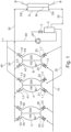
- a third balancing chamber C is connected in parallel to the first and second balancing chambers A, B.
- the third balance chamber has two inlets Z5, Z6, which are connected to the same line 10 as the inlets Z1 and Z3 of the first and second balance chamber A, B.
- the third balancing chamber is supplied with fresh dialysate from line 10 at both inlets. Used dialysate is not fed from the dialyzer to the third balancing chamber. Accordingly, the third balancing chamber conveys only fresh dialysate from outlets A5, A6 to the dialyzer, which serves as a substitute for the patient by at least partially passing through the dialyzer membrane M into the patient's blood.
- Fresh dialysate is removed from the third balancing chamber C via the same line as the fresh dialysate is removed from the first and second balancing chambers. This line leads directly from the respective outlets of the balancing chamber halves to the dialyzer inlet.
- the operation of the third balancing chamber otherwise corresponds to that of the first and second balancing chambers, i.e. while one half of the balancing chamber is filled with the corresponding valve switching, the other half of the balancing chamber is emptied by the resulting displacement of the wall W and vice versa.
- dialyzer membrane acts as a sterile filter for the substitute.
- a sterile filter specifically designed for the sterilization of substitute is no longer necessary.
- the advantage is that no separate substitution pump, separate tubing set, or separate sterile filter is required.
- the third balancing chamber performs the substitution pump function, and the dialyzer membrane performs the sterile filter function.
- substitution line is fed to the dialyzer through the same line as the dialysate, which is conveyed through the first and second balancing chamber.
- the device may comprise an evaluation and control unit that distributes the medically prescribed amount of substitute evenly over the duration of treatment.
- the device may include an evaluation and control unit that distributes the medically prescribed substitution dose unevenly over the course of treatment. This means, for example, that the substitution dose may be higher or lower at the beginning of treatment than at the end.
- High-flux dialyzers are filters that have an ultrafiltration rate of 20-70 ml/m 2 * mmHg * h in human blood.
- the device according to the invention is particularly effective in conjunction with a so-called mid-cut-off dialyzer.
- a dialyzer is used, for example, in WO 2015/118046 A , to which reference is made here.
- Such dialyzers exhibit uncontrolled backflushing of dialysate into the bloodstream, which is caused by the internal pressure conditions within the dialyzer.
- These dialyzers must not be operated in HDF mode, as otherwise the loss of albumin would be significantly too high.
- the amount of substituate can be limited to volumes between 2 and 15 l per treatment, preferably to volumes between 5 and 12 l per treatment, and more preferably to volumes between 5 and 10 l per treatment.
Landscapes
- Health & Medical Sciences (AREA)
- Heart & Thoracic Surgery (AREA)
- Urology & Nephrology (AREA)
- Anesthesiology (AREA)
- Vascular Medicine (AREA)
- Engineering & Computer Science (AREA)
- Biomedical Technology (AREA)
- Hematology (AREA)
- Life Sciences & Earth Sciences (AREA)
- Animal Behavior & Ethology (AREA)
- General Health & Medical Sciences (AREA)
- Public Health (AREA)
- Veterinary Medicine (AREA)
- Emergency Medicine (AREA)
- External Artificial Organs (AREA)
Claims (14)
- Appareil de dialyse avec un dialyseur (D) et avec une première chambre de bilan (A) et avec une deuxième chambre de bilan (B), dont chacune présente au moins deux premières (100, 102) et deuxièmes moitiés de chambre de bilan (200, 202) séparées l'une de l'autre par une paroi mobile (W), chaque première moitié de chambre de bilan (100, 102) étant pourvue respectivement d'une première entrée (Z1, Z3) et d'une première sortie (A1, A3), chaque deuxième moitié de chambre de bilan (200, 202) étant pourvue respectivement d'une deuxième entrée (Z2, Z4) et d'une deuxième sortie (A2, A4), les entrées et les sorties (A1-A4, Z1-Z4) étant pourvues de soupapes (1.1-1.4 ; 2.1-2.4) qui sont réalisées pour fermer er ouvrir l'entrée (Z1-Z4) et la sortie (A1-A2) respectives, les premières entrées (Z1 ; Z3) des premières moitiés de chambre de bilan (100 ; 102) étant en communication fluidique avec une source de dialysat frais et les premières sorties (A1 ; A3) des premières moitiés de chambre de bilan (100 ; 102) étant en communication fluidique avec une entrée de dialyseur (DZ) et les deuxièmes entrées (Z2 ; Z4) des deuxièmes moitiés de chambre de bilan (200 ; 202) étant en communication fluidique avec une sortie de dialyseur (DA) et les deuxièmes sorties (A2 ; A4) des deuxièmes moitiés de chambre de bilan (200 ; 202) étant en communication fluidique avec un drain (1), caractérisé en ce que l'appareil de dialyse présente une troisième chambre de bilan (C) qui dispose de deux moitiés de chambre de bilan (104 ; 204) qui sont séparées l'une de l'autre par une paroi mobile (W), chacune des moitiés de chambre de bilan (104 ; 204) disposant respectivement d'une entrée (Z5 ; Z6) et d'une sortie (A5 ; A6) qui sont respectivement pourvues de soupapes (V1-V4) qui sont réalisées pour ouvrir et pour fermer l'entrée (Z5 ; Z6) et la sortie (A5 ; A6) respectives, les deux entrées (Z5 ; Z6) étant en communication fluidique avec une source de dialysat frais et les deux sorties (A5 ; A6) étant en communication fluidique avec l'entrée de dialyseur (DZ).
- Appareil de dialyse selon la revendication 1, caractérisé en ce que les deux entrées (Z5 ; Z6) de la troisième chambre de bilan (C) sont en communication fluidique avec la même source de dialysat frais que les premières entrées (Z1 ; Z3) de la première et de la deuxième chambre de bilan (A ; B).
- Appareil de dialyse selon la revendication 1 ou 2, caractérisé en ce que les deux sorties (A5 ; A6) de la troisième chambre de bilan (C) sont en communication fluidique avec la même conduite (30) menant à l'entrée de dialyseur (DZ) que les premières sorties (A2 ; A4) de la première et de la deuxième chambre de bilan (A ; B).
- Appareil de dialyse selon l'une quelconque des revendications précédentes, caractérisé en ce que l'appareil ne présente pas de pompe de substitut pour transporter une solution de substitution dans le sang du patient.
- Appareil de dialyse selon l'une quelconque des revendications précédentes, caractérisé en ce que les moitiés de chambre de bilan (104 ; 204) de la troisième chambre de bilan (C) présentent un volume inférieur à celui des moitiés de chambre de bilan de la première et de la deuxième chambre de bilan (A ; B).
- Appareil de dialyse selon l'une quelconque des revendications précédentes, caractérisé en ce qu'un organe d'étranglement est agencé en amont et/ou en aval de la troisième chambre de bilan (C), lequel est réalisé pour étrangler le flux entrant et/ou le flux sortant de dialysat frais de la troisième chambre de bilan (C).
- Appareil de dialyse selon l'une quelconque des revendications précédentes, caractérisé en ce qu'il est prévu une commande qui est réalisée pour effectuer l'amenée de dialysat frais au dialyseur (D) à partir de la troisième chambre de bilan (C) de manière régulière dans le temps ou irrégulière dans le temps pendant la durée du traitement.
- Appareil de dialyse selon l'une quelconque des revendications précédentes, caractérisé en ce que le dialyseur (D) consiste en un dialyseur à haut débit ou un dialyseur Mid-Cut-Off.
- Unité de commande configurée pour effectuer un procédé pour l'exploitation d'un système de chambre de bilan d'un appareil de dialyse avec une première chambre de bilan (A) et avec une deuxième chambre de bilan (B), dont chacune présente au moins deux premières (100, 102) et deuxièmes moitiés de chambre de bilan (200, 202) séparées l'une de l'autre par une paroi mobile (W), chaque première moitié de chambre de bilan (100, 102) étant pourvue d'une première entrée respective (Z1, Z3) et d'une première sortie respective (A1, A3), chaque deuxième moitié de chambre de bilan (200, 202) étant pourvue d'une deuxième entrée respective (Z2, Z4) et d'une deuxième sortie respective (A2, A4), les entrées et les sorties (A1-A4, Z1-Z4) étant respectivement équipées de soupapes (1.1-1.4 ; 2.1-2.4) qui sont réalisées pour ouvrir et pour fermer l'entrée (Z1-Z4) et la sortie (A1-A4) respectives, les premières entrées (Z1 ; Z3) des premières moitiés de chambre de bilan (100 ; 102) étant en communication fluidique avec une source de dialysat frais et les premières sorties (A1 ; A3) des premières moitiés de chambre de bilan (100 ; 102) étant en communication fluidique avec une entrée de dialyseur (DZ) et les deuxièmes entrées (Z2 ; Z4) des deuxièmes moitiés de chambre de bilan (200 ; 202) étant en communication fluidique avec une sortie de dialyseur (DA) et les deuxièmes sorties (A2 ; A4) des deuxièmes moitiés de chambre de bilan (200 ; 202) étant en communication fluidique avec un drain (1), caractérisé en ce que l'appareil de dialyse présente une troisième chambre de bilan (C) qui dispose de deux moitiés de chambre de bilan (104 ; 204), qui sont séparées l'une de l'autre par une paroi mobile (W), chacune des moitiés de chambre de bilan (104 ; 204) disposant respectivement d'une entrée (Z5 ; Z6) et d'une sortie (A5 ; A6) qui sont pourvues respectivement de soupapes (V1-V4), les deux entrées (Z5 ; Z6) étant en communication fluidique avec une source de dialysat frais et les deux sorties (A5 ; A6) étant en communication fluidique avec l'entrée de dialyseur (DZ), les soupapes (V1-V4) étant exploitées pour transporter du dialysat frais de la troisième chambre de bilan (C) à l'entrée de dialyseur (DZ).
- Unité de commande selon la revendication 9, caractérisée en ce que les soupapes (V1-V4) de la troisième chambre de bilan sont exploitées de manière à obtenir un flux continu de dialysat frais depuis la troisième chambre de bilan (C) vers l'entrée de dialyseur (DZ).
- Unité de commande selon la revendication 9 ou 10, caractérisée en ce que la troisième chambre de bilan (C) est exploitée de manière continue ou discontinue.
- Unité de commande selon l'une quelconque des revendications 9 à 11 , caractérisée en ce que l'amenée de dialysat frais à la troisième chambre de bilan (C) et/ou l'évacuation de dialysat frais depuis la troisième chambre d'équilibrage (C) vers l'entrée de dialyseur sont étranglées.
- Unité de commande selon l'une quelconque des revendications 9 à 12, caractérisée en ce que la troisième chambre de bilan (C) est exploitée de telle sorte que le débit de dialysat frais de la troisième chambre de bilan (C) vers l'entrée de dialyseur est constant ou varie pendant la durée du traitement.
- Unité de commande selon l'une quelconque des revendications 9 à 13, caractérisée en ce qu'aucune pompe de substitut n'est utilisée pour amener un substitut au patient.
Applications Claiming Priority (2)
| Application Number | Priority Date | Filing Date | Title |
|---|---|---|---|
| DE102019118521.1A DE102019118521A1 (de) | 2019-07-09 | 2019-07-09 | Dialysegerät und Verfahren zum Betreiben eines Bilanzkammersystems eines Dialysegerätes |
| PCT/EP2020/069396 WO2021005164A1 (fr) | 2019-07-09 | 2020-07-09 | Appareil de dialyse à trois chambres d'équilibrage |
Publications (2)
| Publication Number | Publication Date |
|---|---|
| EP3996768A1 EP3996768A1 (fr) | 2022-05-18 |
| EP3996768B1 true EP3996768B1 (fr) | 2025-05-07 |
Family
ID=71607961
Family Applications (1)
| Application Number | Title | Priority Date | Filing Date |
|---|---|---|---|
| EP20739938.7A Active EP3996768B1 (fr) | 2019-07-09 | 2020-07-09 | Machine de dialyse avec trois chambres d'équilibre |
Country Status (5)
| Country | Link |
|---|---|
| US (1) | US12090258B2 (fr) |
| EP (1) | EP3996768B1 (fr) |
| CN (1) | CN114144211A (fr) |
| DE (1) | DE102019118521A1 (fr) |
| WO (1) | WO2021005164A1 (fr) |
Family Cites Families (6)
| Publication number | Priority date | Publication date | Assignee | Title |
|---|---|---|---|---|
| DE3837498A1 (de) * | 1988-11-04 | 1990-05-17 | Fresenius Ag | Verfahren und vorrichtung zur ultrafiltration bei der haemodialyse |
| DE19708391C1 (de) * | 1997-03-01 | 1998-10-22 | Fresenius Medical Care De Gmbh | Verfahren und Vorrichtung zur Ultrafiltration bei der Hämodialyse |
| US8038639B2 (en) | 2004-11-04 | 2011-10-18 | Baxter International Inc. | Medical fluid system with flexible sheeting disposable unit |
| US8512553B2 (en) * | 2007-07-05 | 2013-08-20 | Baxter International Inc. | Extracorporeal dialysis ready peritoneal dialysis machine |
| ES2927071T3 (es) | 2014-02-06 | 2022-11-02 | Gambro Lundia Ab | Hemodializador para purificar la sangre |
| DE102019130294A1 (de) * | 2019-11-11 | 2021-05-12 | Fresenius Medical Care Deutschland Gmbh | Dialysemaschine zur Durchführung einer Push-Pull-Dialysebehandlung |
-
2019
- 2019-07-09 DE DE102019118521.1A patent/DE102019118521A1/de active Pending
-
2020
- 2020-07-09 WO PCT/EP2020/069396 patent/WO2021005164A1/fr not_active Ceased
- 2020-07-09 CN CN202080049960.0A patent/CN114144211A/zh active Pending
- 2020-07-09 US US17/625,111 patent/US12090258B2/en active Active
- 2020-07-09 EP EP20739938.7A patent/EP3996768B1/fr active Active
Also Published As
| Publication number | Publication date |
|---|---|
| WO2021005164A1 (fr) | 2021-01-14 |
| US12090258B2 (en) | 2024-09-17 |
| CN114144211A (zh) | 2022-03-04 |
| EP3996768A1 (fr) | 2022-05-18 |
| US20220257842A1 (en) | 2022-08-18 |
| DE102019118521A1 (de) | 2021-01-14 |
Similar Documents
| Publication | Publication Date | Title |
|---|---|---|
| EP0867195B1 (fr) | Dispositif pour l'ultrafiltration pendant une hémodialyse | |
| EP2579912B1 (fr) | Dispositif et procédé de circulation de liquides dans l'unité de traitement d'un dispositif de traitement médical, en particulier dans le dialyseur d'un dispositif de dialyse | |
| EP0692268B2 (fr) | Préparation du liquide de substitution dans un appareil d'hémofiltration ou d'hémodiafiltration | |
| EP3554578B1 (fr) | Dispositif de conduite de sang destiné à effectuer un traitement de sang extracorporel, système de traitement de sang | |
| DE4240681C2 (de) | Vorrichtung zur Hämodialyse ohne Antikoagulation | |
| EP2640439A1 (fr) | Procédé et dispositif pour atteindre le mieux possible l'objectif de substitution lors de l'ultrafiltration du sang | |
| DE3841863A1 (de) | Vorrichtung zur kontinuierlichen haemofiltration und haemodiafiltration | |
| EP2482868B1 (fr) | Dispositif de traitement par dialyse et procédé d'équilibrage du liquide de dialyse frais et usagé | |
| WO2022223669A1 (fr) | Procédé de commande d'un dispositif de traitement du sang et dispositifs associés | |
| EP3996769B1 (fr) | Machine de dialyse avec deux chambres d'équilibre qui sont en communication fluidique l'une avec l'autre | |
| EP3500319B1 (fr) | Dispositif pour préparer un liquide de dialyse et dispositif de dialyse | |
| EP3996768B1 (fr) | Machine de dialyse avec trois chambres d'équilibre | |
| EP3773791B1 (fr) | Dispositif de commande ou de réglage et dispositif de traitement de sang pour un traitement à aiguille unique | |
| EP0366950B1 (fr) | Appareil d'hémodialyse avec dispositif de dégazage | |
| EP0513672B1 (fr) | Dispositif de traitement du sang avec équilibrage volumique du débit | |
| DE102009048561B4 (de) | Vorrichtung zur Dialysebehandlung | |
| DE102021132723A1 (de) | Blutbehandlungsvorrichtung mit gekoppelter Blutpumpe und Drucklufteinrichtung | |
| DE102016010434B4 (de) | Blutbehandlungsvorrichtung | |
| WO2026082673A1 (fr) | Préparation d'orifices d'un dispositif de traitement médical pour une session de traitement à venir | |
| EP3402547B1 (fr) | Dispositif pour effectuer un traitement extracorporel du sang | |
| DE3834125C1 (en) | Method of preventing the back-filtration of haemodialysis solution during haemodialysis | |
| DE202017000613U1 (de) | Vorrichtung für eine Extrakorporale Blutbehandlung |
Legal Events
| Date | Code | Title | Description |
|---|---|---|---|
| STAA | Information on the status of an ep patent application or granted ep patent |
Free format text: STATUS: UNKNOWN |
|
| STAA | Information on the status of an ep patent application or granted ep patent |
Free format text: STATUS: THE INTERNATIONAL PUBLICATION HAS BEEN MADE |
|
| PUAI | Public reference made under article 153(3) epc to a published international application that has entered the european phase |
Free format text: ORIGINAL CODE: 0009012 |
|
| STAA | Information on the status of an ep patent application or granted ep patent |
Free format text: STATUS: REQUEST FOR EXAMINATION WAS MADE |
|
| 17P | Request for examination filed |
Effective date: 20220204 |
|
| AK | Designated contracting states |
Kind code of ref document: A1 Designated state(s): AL AT BE BG CH CY CZ DE DK EE ES FI FR GB GR HR HU IE IS IT LI LT LU LV MC MK MT NL NO PL PT RO RS SE SI SK SM TR |
|
| DAV | Request for validation of the european patent (deleted) | ||
| DAX | Request for extension of the european patent (deleted) | ||
| GRAP | Despatch of communication of intention to grant a patent |
Free format text: ORIGINAL CODE: EPIDOSNIGR1 |
|
| STAA | Information on the status of an ep patent application or granted ep patent |
Free format text: STATUS: GRANT OF PATENT IS INTENDED |
|
| INTG | Intention to grant announced |
Effective date: 20241206 |
|
| GRAS | Grant fee paid |
Free format text: ORIGINAL CODE: EPIDOSNIGR3 |
|
| GRAA | (expected) grant |
Free format text: ORIGINAL CODE: 0009210 |
|
| STAA | Information on the status of an ep patent application or granted ep patent |
Free format text: STATUS: THE PATENT HAS BEEN GRANTED |
|
| AK | Designated contracting states |
Kind code of ref document: B1 Designated state(s): AL AT BE BG CH CY CZ DE DK EE ES FI FR GB GR HR HU IE IS IT LI LT LU LV MC MK MT NL NO PL PT RO RS SE SI SK SM TR |
|
| P01 | Opt-out of the competence of the unified patent court (upc) registered |
Free format text: CASE NUMBER: APP_15508/2025 Effective date: 20250331 |
|
| REG | Reference to a national code |
Ref country code: GB Ref legal event code: FG4D Free format text: NOT ENGLISH |
|
| REG | Reference to a national code |
Ref country code: CH Ref legal event code: EP |
|
| REG | Reference to a national code |
Ref country code: DE Ref legal event code: R096 Ref document number: 502020011013 Country of ref document: DE |
|
| REG | Reference to a national code |
Ref country code: IE Ref legal event code: FG4D Free format text: LANGUAGE OF EP DOCUMENT: GERMAN |
|
| PGFP | Annual fee paid to national office [announced via postgrant information from national office to epo] |
Ref country code: GB Payment date: 20250619 Year of fee payment: 6 |
|
| PGFP | Annual fee paid to national office [announced via postgrant information from national office to epo] |
Ref country code: FR Payment date: 20250620 Year of fee payment: 6 |
|
| REG | Reference to a national code |
Ref country code: NL Ref legal event code: MP Effective date: 20250507 |
|
| PG25 | Lapsed in a contracting state [announced via postgrant information from national office to epo] |
Ref country code: ES Free format text: LAPSE BECAUSE OF FAILURE TO SUBMIT A TRANSLATION OF THE DESCRIPTION OR TO PAY THE FEE WITHIN THE PRESCRIBED TIME-LIMIT Effective date: 20250507 Ref country code: PT Free format text: LAPSE BECAUSE OF FAILURE TO SUBMIT A TRANSLATION OF THE DESCRIPTION OR TO PAY THE FEE WITHIN THE PRESCRIBED TIME-LIMIT Effective date: 20250908 Ref country code: FI Free format text: LAPSE BECAUSE OF FAILURE TO SUBMIT A TRANSLATION OF THE DESCRIPTION OR TO PAY THE FEE WITHIN THE PRESCRIBED TIME-LIMIT Effective date: 20250507 |
|
| PGFP | Annual fee paid to national office [announced via postgrant information from national office to epo] |
Ref country code: DE Payment date: 20250620 Year of fee payment: 6 |
|
| REG | Reference to a national code |
Ref country code: LT Ref legal event code: MG9D |
|
| PG25 | Lapsed in a contracting state [announced via postgrant information from national office to epo] |
Ref country code: NO Free format text: LAPSE BECAUSE OF FAILURE TO SUBMIT A TRANSLATION OF THE DESCRIPTION OR TO PAY THE FEE WITHIN THE PRESCRIBED TIME-LIMIT Effective date: 20250807 Ref country code: GR Free format text: LAPSE BECAUSE OF FAILURE TO SUBMIT A TRANSLATION OF THE DESCRIPTION OR TO PAY THE FEE WITHIN THE PRESCRIBED TIME-LIMIT Effective date: 20250808 |
|
| PG25 | Lapsed in a contracting state [announced via postgrant information from national office to epo] |
Ref country code: NL Free format text: LAPSE BECAUSE OF FAILURE TO SUBMIT A TRANSLATION OF THE DESCRIPTION OR TO PAY THE FEE WITHIN THE PRESCRIBED TIME-LIMIT Effective date: 20250507 Ref country code: PL Free format text: LAPSE BECAUSE OF FAILURE TO SUBMIT A TRANSLATION OF THE DESCRIPTION OR TO PAY THE FEE WITHIN THE PRESCRIBED TIME-LIMIT Effective date: 20250507 |
|
| PG25 | Lapsed in a contracting state [announced via postgrant information from national office to epo] |
Ref country code: BG Free format text: LAPSE BECAUSE OF FAILURE TO SUBMIT A TRANSLATION OF THE DESCRIPTION OR TO PAY THE FEE WITHIN THE PRESCRIBED TIME-LIMIT Effective date: 20250507 |
|
| PG25 | Lapsed in a contracting state [announced via postgrant information from national office to epo] |
Ref country code: HR Free format text: LAPSE BECAUSE OF FAILURE TO SUBMIT A TRANSLATION OF THE DESCRIPTION OR TO PAY THE FEE WITHIN THE PRESCRIBED TIME-LIMIT Effective date: 20250507 |
|
| PG25 | Lapsed in a contracting state [announced via postgrant information from national office to epo] |
Ref country code: RS Free format text: LAPSE BECAUSE OF FAILURE TO SUBMIT A TRANSLATION OF THE DESCRIPTION OR TO PAY THE FEE WITHIN THE PRESCRIBED TIME-LIMIT Effective date: 20250807 |
|
| PG25 | Lapsed in a contracting state [announced via postgrant information from national office to epo] |
Ref country code: IS Free format text: LAPSE BECAUSE OF FAILURE TO SUBMIT A TRANSLATION OF THE DESCRIPTION OR TO PAY THE FEE WITHIN THE PRESCRIBED TIME-LIMIT Effective date: 20250907 |
|
| PG25 | Lapsed in a contracting state [announced via postgrant information from national office to epo] |
Ref country code: LV Free format text: LAPSE BECAUSE OF FAILURE TO SUBMIT A TRANSLATION OF THE DESCRIPTION OR TO PAY THE FEE WITHIN THE PRESCRIBED TIME-LIMIT Effective date: 20250507 |
|
| PG25 | Lapsed in a contracting state [announced via postgrant information from national office to epo] |
Ref country code: DK Free format text: LAPSE BECAUSE OF FAILURE TO SUBMIT A TRANSLATION OF THE DESCRIPTION OR TO PAY THE FEE WITHIN THE PRESCRIBED TIME-LIMIT Effective date: 20250507 Ref country code: SM Free format text: LAPSE BECAUSE OF FAILURE TO SUBMIT A TRANSLATION OF THE DESCRIPTION OR TO PAY THE FEE WITHIN THE PRESCRIBED TIME-LIMIT Effective date: 20250507 |
|
| PG25 | Lapsed in a contracting state [announced via postgrant information from national office to epo] |
Ref country code: CZ Free format text: LAPSE BECAUSE OF FAILURE TO SUBMIT A TRANSLATION OF THE DESCRIPTION OR TO PAY THE FEE WITHIN THE PRESCRIBED TIME-LIMIT Effective date: 20250507 |
|
| PG25 | Lapsed in a contracting state [announced via postgrant information from national office to epo] |
Ref country code: EE Free format text: LAPSE BECAUSE OF FAILURE TO SUBMIT A TRANSLATION OF THE DESCRIPTION OR TO PAY THE FEE WITHIN THE PRESCRIBED TIME-LIMIT Effective date: 20250507 |
|
| PG25 | Lapsed in a contracting state [announced via postgrant information from national office to epo] |
Ref country code: SK Free format text: LAPSE BECAUSE OF FAILURE TO SUBMIT A TRANSLATION OF THE DESCRIPTION OR TO PAY THE FEE WITHIN THE PRESCRIBED TIME-LIMIT Effective date: 20250507 Ref country code: RO Free format text: LAPSE BECAUSE OF FAILURE TO SUBMIT A TRANSLATION OF THE DESCRIPTION OR TO PAY THE FEE WITHIN THE PRESCRIBED TIME-LIMIT Effective date: 20250507 |
|
| PG25 | Lapsed in a contracting state [announced via postgrant information from national office to epo] |
Ref country code: IT Free format text: LAPSE BECAUSE OF FAILURE TO SUBMIT A TRANSLATION OF THE DESCRIPTION OR TO PAY THE FEE WITHIN THE PRESCRIBED TIME-LIMIT Effective date: 20250507 |
|
| REG | Reference to a national code |
Ref country code: DE Ref legal event code: R097 Ref document number: 502020011013 Country of ref document: DE |
|
| REG | Reference to a national code |
Ref country code: CH Ref legal event code: H13 Free format text: ST27 STATUS EVENT CODE: U-0-0-H10-H13 (AS PROVIDED BY THE NATIONAL OFFICE) Effective date: 20260224 |
|
| PLBE | No opposition filed within time limit |
Free format text: ORIGINAL CODE: 0009261 |
|
| STAA | Information on the status of an ep patent application or granted ep patent |
Free format text: STATUS: NO OPPOSITION FILED WITHIN TIME LIMIT |
|
| PG25 | Lapsed in a contracting state [announced via postgrant information from national office to epo] |
Ref country code: LU Free format text: LAPSE BECAUSE OF NON-PAYMENT OF DUE FEES Effective date: 20250709 |
|
| REG | Reference to a national code |
Ref country code: CH Ref legal event code: L10 Free format text: ST27 STATUS EVENT CODE: U-0-0-L10-L00 (AS PROVIDED BY THE NATIONAL OFFICE) Effective date: 20260318 |
|
| REG | Reference to a national code |
Ref country code: BE Ref legal event code: MM Effective date: 20250731 |
|
| 26N | No opposition filed |
Effective date: 20260210 |
|
| PG25 | Lapsed in a contracting state [announced via postgrant information from national office to epo] |
Ref country code: BE Free format text: LAPSE BECAUSE OF NON-PAYMENT OF DUE FEES Effective date: 20250731 |
|
| PG25 | Lapsed in a contracting state [announced via postgrant information from national office to epo] |
Ref country code: CH Free format text: LAPSE BECAUSE OF NON-PAYMENT OF DUE FEES Effective date: 20250731 |