EP2580448B1 - Turbine à gaz et procédé permettant de faire fonctionner ladite turbine à gaz - Google Patents
Turbine à gaz et procédé permettant de faire fonctionner ladite turbine à gaz Download PDFInfo
- Publication number
- EP2580448B1 EP2580448B1 EP11787662.3A EP11787662A EP2580448B1 EP 2580448 B1 EP2580448 B1 EP 2580448B1 EP 11787662 A EP11787662 A EP 11787662A EP 2580448 B1 EP2580448 B1 EP 2580448B1
- Authority
- EP
- European Patent Office
- Prior art keywords
- liquid fuel
- gas turbine
- fuel
- shop air
- combustion
- Prior art date
- Legal status (The legal status is an assumption and is not a legal conclusion. Google has not performed a legal analysis and makes no representation as to the accuracy of the status listed.)
- Not-in-force
Links
- 238000000034 method Methods 0.000 title claims description 17
- 239000000446 fuel Substances 0.000 claims description 158
- 239000007788 liquid Substances 0.000 claims description 88
- 238000002485 combustion reaction Methods 0.000 claims description 51
- 238000005273 aeration Methods 0.000 claims description 23
- 238000011144 upstream manufacturing Methods 0.000 claims description 5
- 238000010438 heat treatment Methods 0.000 claims description 3
- 238000005086 pumping Methods 0.000 claims description 2
- 239000007789 gas Substances 0.000 description 77
- 230000000694 effects Effects 0.000 description 7
- 239000000203 mixture Substances 0.000 description 7
- 239000000523 sample Substances 0.000 description 3
- 239000007921 spray Substances 0.000 description 3
- 238000000889 atomisation Methods 0.000 description 2
- 239000000567 combustion gas Substances 0.000 description 2
- 239000002737 fuel gas Substances 0.000 description 2
- VNWKTOKETHGBQD-UHFFFAOYSA-N methane Chemical compound C VNWKTOKETHGBQD-UHFFFAOYSA-N 0.000 description 2
- 239000000243 solution Substances 0.000 description 2
- XLYOFNOQVPJJNP-UHFFFAOYSA-N water Substances O XLYOFNOQVPJJNP-UHFFFAOYSA-N 0.000 description 2
- 238000009792 diffusion process Methods 0.000 description 1
- 238000002347 injection Methods 0.000 description 1
- 239000007924 injection Substances 0.000 description 1
- 238000012423 maintenance Methods 0.000 description 1
- 239000003345 natural gas Substances 0.000 description 1
- 238000010248 power generation Methods 0.000 description 1
Images


Classifications
-
- F—MECHANICAL ENGINEERING; LIGHTING; HEATING; WEAPONS; BLASTING
- F02—COMBUSTION ENGINES; HOT-GAS OR COMBUSTION-PRODUCT ENGINE PLANTS
- F02C—GAS-TURBINE PLANTS; AIR INTAKES FOR JET-PROPULSION PLANTS; CONTROLLING FUEL SUPPLY IN AIR-BREATHING JET-PROPULSION PLANTS
- F02C7/00—Features, components parts, details or accessories, not provided for in, or of interest apart form groups F02C1/00 - F02C6/00; Air intakes for jet-propulsion plants
- F02C7/22—Fuel supply systems
-
- B—PERFORMING OPERATIONS; TRANSPORTING
- B01—PHYSICAL OR CHEMICAL PROCESSES OR APPARATUS IN GENERAL
- B01F—MIXING, e.g. DISSOLVING, EMULSIFYING OR DISPERSING
- B01F23/00—Mixing according to the phases to be mixed, e.g. dispersing or emulsifying
- B01F23/20—Mixing gases with liquids
- B01F23/23—Mixing gases with liquids by introducing gases into liquid media, e.g. for producing aerated liquids
- B01F23/232—Mixing gases with liquids by introducing gases into liquid media, e.g. for producing aerated liquids using flow-mixing means for introducing the gases, e.g. baffles
-
- B—PERFORMING OPERATIONS; TRANSPORTING
- B01—PHYSICAL OR CHEMICAL PROCESSES OR APPARATUS IN GENERAL
- B01F—MIXING, e.g. DISSOLVING, EMULSIFYING OR DISPERSING
- B01F25/00—Flow mixers; Mixers for falling materials, e.g. solid particles
- B01F25/30—Injector mixers
- B01F25/31—Injector mixers in conduits or tubes through which the main component flows
- B01F25/313—Injector mixers in conduits or tubes through which the main component flows wherein additional components are introduced in the centre of the conduit
- B01F25/3133—Injector mixers in conduits or tubes through which the main component flows wherein additional components are introduced in the centre of the conduit characterised by the specific design of the injector
- B01F25/31331—Perforated, multi-opening, with a plurality of holes
-
- F—MECHANICAL ENGINEERING; LIGHTING; HEATING; WEAPONS; BLASTING
- F02—COMBUSTION ENGINES; HOT-GAS OR COMBUSTION-PRODUCT ENGINE PLANTS
- F02C—GAS-TURBINE PLANTS; AIR INTAKES FOR JET-PROPULSION PLANTS; CONTROLLING FUEL SUPPLY IN AIR-BREATHING JET-PROPULSION PLANTS
- F02C3/00—Gas-turbine plants characterised by the use of combustion products as the working fluid
- F02C3/20—Gas-turbine plants characterised by the use of combustion products as the working fluid using a special fuel, oxidant, or dilution fluid to generate the combustion products
- F02C3/24—Gas-turbine plants characterised by the use of combustion products as the working fluid using a special fuel, oxidant, or dilution fluid to generate the combustion products the fuel or oxidant being liquid at standard temperature and pressure
-
- F—MECHANICAL ENGINEERING; LIGHTING; HEATING; WEAPONS; BLASTING
- F02—COMBUSTION ENGINES; HOT-GAS OR COMBUSTION-PRODUCT ENGINE PLANTS
- F02C—GAS-TURBINE PLANTS; AIR INTAKES FOR JET-PROPULSION PLANTS; CONTROLLING FUEL SUPPLY IN AIR-BREATHING JET-PROPULSION PLANTS
- F02C7/00—Features, components parts, details or accessories, not provided for in, or of interest apart form groups F02C1/00 - F02C6/00; Air intakes for jet-propulsion plants
- F02C7/22—Fuel supply systems
- F02C7/222—Fuel flow conduits, e.g. manifolds
-
- F—MECHANICAL ENGINEERING; LIGHTING; HEATING; WEAPONS; BLASTING
- F02—COMBUSTION ENGINES; HOT-GAS OR COMBUSTION-PRODUCT ENGINE PLANTS
- F02C—GAS-TURBINE PLANTS; AIR INTAKES FOR JET-PROPULSION PLANTS; CONTROLLING FUEL SUPPLY IN AIR-BREATHING JET-PROPULSION PLANTS
- F02C7/00—Features, components parts, details or accessories, not provided for in, or of interest apart form groups F02C1/00 - F02C6/00; Air intakes for jet-propulsion plants
- F02C7/22—Fuel supply systems
- F02C7/236—Fuel delivery systems comprising two or more pumps
- F02C7/2365—Fuel delivery systems comprising two or more pumps comprising an air supply system for the atomisation of fuel
-
- F—MECHANICAL ENGINEERING; LIGHTING; HEATING; WEAPONS; BLASTING
- F23—COMBUSTION APPARATUS; COMBUSTION PROCESSES
- F23K—FEEDING FUEL TO COMBUSTION APPARATUS
- F23K5/00—Feeding or distributing other fuel to combustion apparatus
- F23K5/02—Liquid fuel
- F23K5/08—Preparation of fuel
- F23K5/10—Mixing with other fluids
-
- F—MECHANICAL ENGINEERING; LIGHTING; HEATING; WEAPONS; BLASTING
- F23—COMBUSTION APPARATUS; COMBUSTION PROCESSES
- F23R—GENERATING COMBUSTION PRODUCTS OF HIGH PRESSURE OR HIGH VELOCITY, e.g. GAS-TURBINE COMBUSTION CHAMBERS
- F23R3/00—Continuous combustion chambers using liquid or gaseous fuel
- F23R3/28—Continuous combustion chambers using liquid or gaseous fuel characterised by the fuel supply
-
- F—MECHANICAL ENGINEERING; LIGHTING; HEATING; WEAPONS; BLASTING
- F05—INDEXING SCHEMES RELATING TO ENGINES OR PUMPS IN VARIOUS SUBCLASSES OF CLASSES F01-F04
- F05D—INDEXING SCHEME FOR ASPECTS RELATING TO NON-POSITIVE-DISPLACEMENT MACHINES OR ENGINES, GAS-TURBINES OR JET-PROPULSION PLANTS
- F05D2260/00—Function
- F05D2260/85—Starting
-
- F—MECHANICAL ENGINEERING; LIGHTING; HEATING; WEAPONS; BLASTING
- F23—COMBUSTION APPARATUS; COMBUSTION PROCESSES
- F23K—FEEDING FUEL TO COMBUSTION APPARATUS
- F23K2300/00—Pretreatment and supply of liquid fuel
- F23K2300/10—Pretreatment
- F23K2300/103—Mixing with other fluids
-
- F—MECHANICAL ENGINEERING; LIGHTING; HEATING; WEAPONS; BLASTING
- F23—COMBUSTION APPARATUS; COMBUSTION PROCESSES
- F23K—FEEDING FUEL TO COMBUSTION APPARATUS
- F23K2900/00—Special features of, or arrangements for fuel supplies
- F23K2900/05084—Creating a combustible foam of liquid fuels and air
Definitions
- the present invention relates to gas turbine comprising a combustion system with several burners, a conduit system with a fuel manifold for providing the burners with liquid fuel and a system for aerating the liquid fuel with gas.
- a gas duct or gas flow path is routed through a combustion section/system located between a compressor and a turbine section.
- the combustion section may include an annular array of combustors. High pressure air from the compressor flows through the combustion section where it is mixed with fuel and burned.
- the combustors each comprise a burner for igniting the air/fuel mixture especially during start up of the gas turbine.
- a high-pressure and a low-pressure turbine of the turbine section are mechanically connected and together drive an output power shaft.
- a low-pressure turbine (power turbine) is mechanically independent, i.e. only drives the output power shaft, and a high-pressure turbine, or so called compressor turbine, drives the compressor. This combination acts as a gas generator for the low-pressure turbine.
- the combustion gases exit the turbine section through an exhaust duct.
- DLE Dry Low Emissions
- a route chosen for the liquid DLE combustion system showing the lowest emissions is to use a high degree of atomization of the fuel in the main operation range. This leads to larger droplets and a less distributes fuel spray during start, due to a reduced mass flow, i.e. a reduced pressure/fuel feed pressure, which makes it harder for the fuel to ignite and the DLE gas turbine to start.
- a further effect adding to the start problem is that a pressure head loss, i.e. by a gravitational effect by a location of a burner over ground relative to neighbouring burners, becomes more important due to the reduced fuel flow. This difference redistributes the fuel flow from higher burners to lower burners making it more difficult for the higher burners to ignite.
- Some other solutions have been proposed injecting a mixture comprising fuel gas into a liquid fuel nozzle during start to promote ignition, known as effervescent atomization.
- EP 0 849 532 A2 discloses a gas turbine and an operation method of the gas turbine with an auxiliary gas flow is fed in a liquid fuel flow inside an injection nozzle on ignition.
- DLE Dry Low Emissions
- the objective is achieved, according to the present invention, by providing a gas turbine according the independent arrangement claim.
- Said gas turbine comprises a combustion system with several burners, a conduit system with a fuel manifold for providing the burners with liquid fuel and a system for aerating the liquid fuel with gas according the independent claim.
- the inventive aerating system comprises a fuel feed for supplying a combustion system of a gas turbine with liquid fuel and a flow body with a feed supplying said flow body with gas under pressure higher than a pressure of said liquid fuel.
- Said flow body is arranged in said fuel feed flown by said liquid fuel while flowing in said fuel feed.
- Said flow body further comprises a surface with at least one outlet opening for exhausting said gas through said at least one outlet opening of said flow body into said liquid fuel to aerate said liquid fuel with said gas.
- a fuel feed for supplying a gas turbine, particularly for supplying a DLE Combustion System of a gas turbine, with liquid fuel.
- a flow body is provided with gas under pressure higher than a pressure of said liquid fuel.
- the flow body a three-dimensional body formed as a ball, preferably as a cylinder or elongated body, is arranged in said fuel feed to be flown by, i.e. circulated around by, said liquid fuel while said liquid fuel flowing in said fuel feed.
- Said flow body comprises a surface with at least one outlet opening wherein said gas could exhaust (from inside the - hollow - flow body) through said at least one outlet opening into said liquid fuel while said liquid fuel passing/circulate around said flow body. While this exhausting of the gas said liquid fuel is aerated with said gas.
- the invention is based on the insight, that aerating liquid fuel with gas - while producing bubbles in the gas - will reduce a density of liquid fuel and will increase a volume of liquid fuel.
- the change of density of liquid fuel leads to a reduction of a pressure head of a mixture - injected for ignition.
- the change of density further leads to an increase of the pressure in the fuel feed to compensate for the increased volume being fed, i.e. pumped through.
- the invention is also based on the insight, that increasing the pressure of the fuel in the fuel feed the impact by the pressure head could significantly be reduced - particularly during the start/ignition of the gas turbine - without requiring variable geometry or separate fuel gas.
- the fuel feed i.e. fuel line
- a mixing section i.e. aeration section/system
- shop air pressurized air from a source outside the gas turbine
- the density of the liquid fuel is reduced, i.e. the volume of the liquid fuel is increased.
- the pressure head of the injected mixture is reduced and the pressure in the fuel feed is increased to compensate for the increased volume being fed, i.e. pumped through.
- the invention offers a robust, low cost, low maintenance alternative to variable geometry burner/nozzle - utilising resources already available (pressurised air) on site.
- said flow body comprises several outlet openings increasing the effectiveness of aerating the liquid fuel.
- Each of the outlet openings could have the same size. Alternatively, the outlet openings could have different sizes.
- the size of an outlet opening in general, the size of the surface of the flow body as well as the pressure of the gas and a (aeration) mixing rate of the gas and the liquid fuel - all effecting a grade of aeration - could be a function of a size of said gas turbine, particularly of a size of a combustion system of said gas turbine.
- Gas turbines of larger size i.e. combustions systems of larger size, are more susceptible to gravitational effects by the location of the burner over ground - relative to neighbouring burners - and are more susceptible to pressure head losses which could be countered by a higher aeration using the invention.
- the flow body is formed, i.e. shaped, as a perforated bluff body, wherein a grade of said perforation could be a function of a size of said gas turbine, particularly of a size of a combustion system of said gas turbine, again, i.e. according to the effects described above.
- the flow body is formed as a ball, especially with an annular, polygon, elliptical or oval cross section, or as an elongated body - as well as spherical, in a blocker bar style or in submarine/probe style.
- said gas turbine comprises a Dry Low Emissions (DLE) combustion system supplied with the aerated liquid fuel, particularly during a start up phase of said Dry Low Emission (DLE) combustion system.
- DLE Dry Low Emissions
- the liquid fuel could be a premium fuel, particularly a heating oil.
- the pressure of the liquid fuel before use of aeration - and particularly during starting the turbine - could be about 2 - 3 bar and/or the pressure of the aerated liquid fuel could be about 5 -6 bar.
- the gas could be a highly compressed air, particularly a shop air with said pressure about 7 - 10 bar.
- Preferable a (aeration) mixing rate is about.1:1.
- the aeration system according to the invention is located downstream of a pump pumping the liquid fuel through said fuel feed and located upstream to a manifold, especially a fuel manifold, of a conduit system providing a burner can of said gas turbine, particularly of a combustion system of said gas turbine, with the liquid fuel.
- the gas under pressure could be provided by an external source.
- the gas is shop air. Shop air is normally available at about 7 - 10 bar.
- the system according the invention is used for supplying a Dry Low Combustion system of the gas turbine with aerated liquid fuel, particularly during a starting phase of the Dry Low Combustion system.
- the aeration of the liquid fuel could be gradually reduced and switched off when an ignition of the DLE combustion system has taken place and/or a combustion of said gas turbine is stable.
- the invention could be preferable used for supplying the gas turbine with aerated liquid fuel while starting said gas turbine, particularly while an ignition of said gas turbine, particularly of a Dry Low Combustion system of said gas turbine is taking place.
- the aeration could be gradually reduced and switched off when said ignition of said gas turbine has taken place and/or the combustion of said gas turbine is stable. While switched off the flow body, particularly a perforated bluff body, could generate a low but equal pressure drop for all burners of the combustion system.
- the invention is used in a Dry Low Emission gas turbine for reducing a density of a premium fuel, for example a heating oil, for the Dry Low Emission combustion during a starting phase, i.e. an ignition phase, of the DLE gas turbine.
- a starting phase i.e. an ignition phase
- Reducing the density, i.e. increasing the volume, of the fuel - during the starting phase - leads to a reduction of the pressure head of the injected mixture.
- the change of density further leads to an increase of the pressure in the fuel feed to compensate for the increased volume being fed.
- Figure 1 is an embodiment of a gas turbine 10 in the form of a single-shaft gas turbine.
- the gas turbine 10 comprises a single rotor shaft 12 carrying both a compressor 14 and a power turbine 16.
- a gas duct 34 guides a propulsion gas 18 through the turbine 10 starting from an inflow section 20 via the compressor 14, a combustion section/system 22, the power turbine 16 and an exhaust duct 26.
- the propulsion gas 18 in the form of air flows via an inflow section 20 into the compressor 14.
- the compressor 14 thereupon compresses the propulsion gas 18.
- the propulsion gas 18 then enters the combustion system/section 22 of the turbine 10, in which it is mixed with fuel and ignited in combustors 24.
- the combustion section 22 contains an annular array of (six) combustors 24, of which only one of six is shown in Figure 1 .
- the combusted propulsion gas 18 flows through the turbine 16 expanding thereby and driving the rotor shaft 12.
- the expanded propulsion gas 18 then enters an exhaust duct 26.
- the (six) combustors 24 arranged - as illustrated in Figure 2 in more detail - in an annular array - each comprise a burner 36 for introducing fuel into the inside of the corresponding combustor 24 and igniting the fuel/air mixture.
- Each burner 36 comprises a pilot burner 37.
- the burners 36, i.e. pilot burners 37, are supplied with fuel, which is pumped through a fuel feed/line downstream a fuel pump 50 upstream to a fuel manifold 51, i.e. a fuel inlet 41, for the combustion system 24.
- the burners 36 are supplied with the fuel by a main conduit system 42 as well as a pilot conduit system 43 both connecting the burners 36 and pilot burners 37 with the fuel line 49 using separate conduits (not shown).
- the burners contain fuel inlets 38, 39 for introducing the fuel into the burner 36 and pilot burner 37.
- the pilot fuel is subsequently guided to a burner face where it is introduced to the combustion camber.
- the burners 36-1, 36-2, and 36-3 are located higher over ground than the burners 36-3, 36-4, and 36-5 leading to gravitational effects, i.e. pressure head loss, influencing the distribution of the fuel to the higher burners 36-1, 36-2, and 36-6 and lower burners 36-3, 36-4, and 36-5.
- Figure 3 is showing a diagrammatic representation of the fuel line 49 downstream of a fuel pump 50 and upstream of the fuel manifold 51, i.e. the fuel inlet 41, with a mixing section, a aeration section/system 52, for aerating the liquid fuel 53 with gas/air, i.e. shop air 54.
- the aeration section 52 contains a bluff body 60 comprising a perforation 61 through which the shop air 54 - supplied by an external air source - is introduced to the liquid fuel 53.
- a typical feed pressure for the liquid fuel 53 during start is 2 - 3 bar, whereas the shop air 54 is typically available at 7 - 10 bar.
- Figure 4 is showing the aeration section 52 in more detail according to the invention.
- Figure 4 is showing the bluff body 60 being formed as a ball, arranged in the fuel line 49 to be flown by, i.e. circulated around by, the liquid fuel 53 and supplied with the shop air 54 by a tube 65 empty into the bluff body 60 from outside.
- the surface 62 of the bluff body 60 is perforated 61 wherein the shop air 54 could exhaust (from inside the bluff body 60) into the liquid fuel 53 while that liquid fuel 53 passing/circulate around the bluff body 60.
- the aerated liquid fuel 55 is fed to the fuel manifold 51 as shown in Figure 3 .
- the fuel feed/line 49 is extended 63 in the range of the bluff body 62.
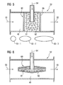
- Figure 5 is showing the bluff body 60 being formed in a blocker bar style, arranged in the fuel line 49 to be flown by, i.e. circulated around by, the liquid fuel 53 and supplied with the shop air 54 by a tube 65 empty into the bluff body 60 from outside.
- the surface 62 of the blocker bar style bluff body 60 is perforated 61 wherein the shop air 54 could exhaust into the liquid fuel 53 while that liquid fuel 53 passing around the bluff body 60.
- the aerated liquid fuel 55 is fed to the fuel manifold 51 as shown in Figure 3 .
- cross section of the blocker bar style bluff body 60 could be realized circular 63-1 or in different elliptical forms 63-2, 63-3.
- Figure 6 is showing the bluff body 60 formed as in submarine/probe style, arranged in the fuel line 49 to be flown by, i.e. circulated around by, the liquid fuel 53 and supplied with the shop air 54 by a tube 65 empty into the bluff body 60 from outside.
- the surface 62 of the submarine/probe style bar style bluff body 60 is perforated 61 wherein the shop air 54 could exhaust into the liquid fuel 53 while that liquid fuel 53 passing around the bluff body 60.
- the aerated liquid fuel 55 is fed to the fuel manifold 51 as shown in Figure 3 .
- the aeration of the liquid fuel 53 by the shop air 54 will operate during the staring phase of the gas turbine 10.
- the aeration section 52 contains the bluff body 60 comprising the perforation 61 through which the shop air 54 is introduced to the liquid fuel 53.
- a typical feed pressure for the liquid fuel 53 during start is 2 - 3 bar, whereas the shop air 54 is typically available at 7 - 10 bar.
Landscapes
- Engineering & Computer Science (AREA)
- Chemical & Material Sciences (AREA)
- Combustion & Propulsion (AREA)
- Mechanical Engineering (AREA)
- General Engineering & Computer Science (AREA)
- Chemical Kinetics & Catalysis (AREA)
- Feeding And Controlling Fuel (AREA)
Claims (12)
- Turbine à gaz (10) comprenant un système de combustion (22) comportant plusieurs brûleurs (36) agencés en un réseau annulaire, un système (42) de conduits comportant un collecteur (51) de combustible servant à fournir du combustible liquide (53) aux brûleurs (36) agencés dans le réseau annulaire, et un système servant à aérer le combustible liquide (53) avec de l'air industriel (54), ledit système servant à aérer le combustible liquide (53) avec de l'air industriel (54) comprenant :- une amenée (49) de combustible amenant le combustible liquide (53) ;- un corps d'écoulement (60) comportant une amenée (65) fournissant ledit corps d'écoulement (60) en air industriel (54) à une pression supérieure à une pression dudit combustible liquide (53) ;- ledit corps d'écoulement (60) étant un corps camus perforé ayant la forme d'une boule, comprenant une surface (62) dotée de plusieurs ouvertures d'échappement (61) pour aérer ledit combustible liquide (53) avec ledit air industriel (54) ;- ledit corps camus perforé étant agencé dans ladite amenée (49) de combustible pour que ledit combustible liquide (53) circule autour de lui pendant qu'il s'écoule dans ladite amenée (49) de combustible ;- ladite amenée (49) de combustible étant étendue (63) à proximité dudit corps camus perforé afin d'assurer une circulation avantageuse du combustible liquide (53) autour dudit corps camus, et- ledit système servant à aérer le combustible liquide (53) avec de l'air industriel (54) étant situé en amont dudit collecteur (51) de combustible.
- Turbine à gaz (10) selon la revendication 1, dans laquelle lesdites plusieurs ouvertures d'échappement (61) sont chacune de la même taille ou d'une taille différente, étant entendu que la taille sera fonction d'une taille de ladite turbine à gaz (10), en particulier d'une taille du système de combustion (22) de ladite turbine à gaz (10).
- Turbine à gaz (10) selon l'une quelconque des revendications précédentes, dans laquelle un calibre de ladite perforation (61) dudit corps d'écoulement (60) est fonction d'une taille de ladite turbine à gaz (10), en particulier d'une taille du système de combustion (22) de ladite turbine à gaz (10).
- Turbine à gaz (10) selon l'une quelconque des revendications précédentes, dans laquelle ladite turbine à gaz (10) comprend un système de combustion (22) sèche à faibles émissions (DLE) alimenté en combustible liquide aéré (53), en particulier pendant une phase de mise en route dudit système de combustion (22) sèche à faibles émissions (DLE).
- Turbine à gaz (10) selon l'une quelconque des revendications précédentes, dans laquelle ledit système peut être situé en aval d'une pompe (50) refoulant ledit combustible liquide (53) dans ladite amenée (49) de combustible.
- Turbine à gaz (10) selon l'une quelconque des revendications précédentes, dans laquelle ledit air industriel (54) peut être fourni par une source externe et/ou dans laquelle ledit combustible liquide (53) peut être un super-combustible, en particulier une huile de chauffe utilisée pour une combustion sèche à faibles émissions.
- Turbine à gaz (10) selon l'une quelconque des revendications précédentes, dans laquelle ledit air industriel (54) est de l'air extrêmement comprimé, en particulier à une pression d'environ 7-10 bars.
- Procédé d'exploitation de ladite turbine à gaz (10) selon l'une quelconque des revendications précédentes, ledit procédé comprenant les étapes consistant :- à mettre à disposition une source dudit air industriel (54) à une pression supérieure à celle dudit combustible liquide (53) ;- à amener ledit air industriel (54) audit corps d'écoulement perforé (62) comprenant lesdites plusieurs ouvertures d'échappement (61) ;- à faire s'écouler ledit combustible liquide (53) autour dudit corps d'écoulement perforé, et- à aérer ledit combustible liquide (53) avec ledit air industriel (54) pendant que ledit air industriel (54) est chassé dans ledit combustible liquide (53) par lesdites plusieurs ouvertures d'échappement (61) dudit corps d'écoulement perforé (62) tandis que ledit combustible liquide (53) circule autour dudit corps d'écoulement perforé (62).
- Procédé selon l'une quelconque des revendications de procédé précédentes, dans lequel ledit procédé est utilisé pour alimenter ladite turbine à gaz (10) en combustible liquide aéré (55) pendant la mise en marche de ladite turbine à gaz (10), en particulier pendant un allumage de ladite turbine à gaz (10), en particulier d'un système (22) de combustion sèche à faibles émissions de ladite turbine à gaz (10), et pour réduire graduellement et couper ladite aération lorsque ledit allumage de ladite turbine à gaz (10) a eu lieu et/ou qu'une combustion de ladite turbine à gaz (10) est stable.
- Procédé selon l'une quelconque des revendications de procédé précédentes, dans lequel ledit procédé est utilisé pour produire des bulles dans ledit combustible liquide (53) et/ou dans lequel ledit procédé est utilisé pour réduire une densité dudit combustible liquide (53), en particulier pendant l'alimentation de ladite turbine à gaz (10) avec ledit combustible liquide (55) de densité moindre durant une phase d'allumage de ladite turbine à gaz (10) et/ou dans lequel ledit procédé est utilisé pour réduire une hauteur de refoulement dudit combustible liquide (53), en particulier pendant l'alimentation de ladite turbine à gaz (10) avec ledit combustible liquide (55) de hauteur de refoulement réduite pendant une phase d'allumage de ladite turbine à gaz (10).
- Procédé selon l'une quelconque des revendications de procédé précédentes, dans lequel ladite pression dudit combustible liquide (53) avant l'utilisation de ladite aération est d'environ 2-3 bars et/ou dans lequel une pression du combustible liquide aéré (55) est d'environ 5-6 bars.
- Procédé selon l'une quelconque des revendications de procédé précédentes, ledit système de combustion (22) étant alimenté en combustible liquide aéré (55) pendant que ledit air industriel (54) et le combustible liquide (53) sont mélangés dans ledit système pour aérer le combustible liquide (53) avec l'air industriel (54) selon un rapport de mélange, ledit rapport de mélange étant fonction d'une taille de ladite turbine à gaz (10), en particulier d'une taille dudit système de combustion (22) de ladite turbine à gaz (10), ledit rapport de mélange étant en particulier de 1:1.
Priority Applications (1)
| Application Number | Priority Date | Filing Date | Title |
|---|---|---|---|
| EP11787662.3A EP2580448B1 (fr) | 2010-12-22 | 2011-11-16 | Turbine à gaz et procédé permettant de faire fonctionner ladite turbine à gaz |
Applications Claiming Priority (3)
| Application Number | Priority Date | Filing Date | Title |
|---|---|---|---|
| EP10196506A EP2469167A1 (fr) | 2010-12-22 | 2010-12-22 | Système d'aération de carburant liquide avec du gaz pour turbine à gaz et procédé d'aération de carburant liquide avec du gaz pour turbine à gaz |
| PCT/EP2011/070245 WO2012084347A2 (fr) | 2010-12-22 | 2011-11-16 | Turbine à gaz et procédé permettant de faire fonctionner ladite turbine à gaz |
| EP11787662.3A EP2580448B1 (fr) | 2010-12-22 | 2011-11-16 | Turbine à gaz et procédé permettant de faire fonctionner ladite turbine à gaz |
Publications (2)
| Publication Number | Publication Date |
|---|---|
| EP2580448A2 EP2580448A2 (fr) | 2013-04-17 |
| EP2580448B1 true EP2580448B1 (fr) | 2015-10-28 |
Family
ID=44546107
Family Applications (2)
| Application Number | Title | Priority Date | Filing Date |
|---|---|---|---|
| EP10196506A Withdrawn EP2469167A1 (fr) | 2010-12-22 | 2010-12-22 | Système d'aération de carburant liquide avec du gaz pour turbine à gaz et procédé d'aération de carburant liquide avec du gaz pour turbine à gaz |
| EP11787662.3A Not-in-force EP2580448B1 (fr) | 2010-12-22 | 2011-11-16 | Turbine à gaz et procédé permettant de faire fonctionner ladite turbine à gaz |
Family Applications Before (1)
| Application Number | Title | Priority Date | Filing Date |
|---|---|---|---|
| EP10196506A Withdrawn EP2469167A1 (fr) | 2010-12-22 | 2010-12-22 | Système d'aération de carburant liquide avec du gaz pour turbine à gaz et procédé d'aération de carburant liquide avec du gaz pour turbine à gaz |
Country Status (3)
| Country | Link |
|---|---|
| US (1) | US20130298569A1 (fr) |
| EP (2) | EP2469167A1 (fr) |
| WO (1) | WO2012084347A2 (fr) |
Families Citing this family (5)
| Publication number | Priority date | Publication date | Assignee | Title |
|---|---|---|---|---|
| GB0902221D0 (en) * | 2009-02-11 | 2009-03-25 | Edwards Ltd | Pilot |
| DE102013003982A1 (de) * | 2013-03-10 | 2014-09-11 | Margret Spiegel | Angewandte Treibstoffe in der Zusammensetzung verändert zur Energiegewinnung anzuwenden. |
| CN105508869A (zh) * | 2014-10-08 | 2016-04-20 | 开立德股份有限公司 | 燃气供应系统 |
| US10520195B2 (en) | 2017-06-09 | 2019-12-31 | General Electric Company | Effervescent atomizing structure and method of operation for rotating detonation propulsion system |
| WO2019018043A1 (fr) * | 2017-07-19 | 2019-01-24 | Parker-Hannifin Corporation | Connecteur multiport à double carburant |
Citations (2)
| Publication number | Priority date | Publication date | Assignee | Title |
|---|---|---|---|---|
| US4189914A (en) * | 1978-06-19 | 1980-02-26 | The United States Of America As Represented By The Administrator Of The National Aeronautics And Space Administration | Supercritical fuel injection system |
| US20100154424A1 (en) * | 2008-12-18 | 2010-06-24 | Christopher Zdzislaw Twardochleb | Low cross-talk gas turbine fuel injector |
Family Cites Families (13)
| Publication number | Priority date | Publication date | Assignee | Title |
|---|---|---|---|---|
| US4419863A (en) * | 1981-09-30 | 1983-12-13 | United Technologies Corporation | Fuel-air mixing apparatus |
| DE3232938C2 (de) * | 1982-09-04 | 1984-06-28 | Kohlensäurewerke C. G. Rommenhöller GmbH, 3490 Bad Driburg-Herste | Verfahren und Vorrichtung zur Lösung von Gas, insbesondere Kohlendioxid in flüssigem Brennstoff und dessen Verteilung in Verbrennungsluft in übersättigtem Zustand |
| US4835962A (en) * | 1986-07-11 | 1989-06-06 | Avco Corporation | Fuel atomization apparatus for gas turbine engine |
| US5051065A (en) * | 1989-04-07 | 1991-09-24 | Vickers, Incorporated | Power transmission |
| US5813232A (en) | 1995-06-05 | 1998-09-29 | Allison Engine Company, Inc. | Dry low emission combustor for gas turbine engines |
| DE19653059A1 (de) * | 1996-12-19 | 1998-06-25 | Asea Brown Boveri | Verfahren zum Betrieb eines Brenners |
| US6293525B1 (en) * | 1998-06-15 | 2001-09-25 | Irwin Ginsburgh | Economical apparatus for producing improved combustion and safety-enhanced fuel |
| DE102004003033A1 (de) * | 2004-01-21 | 2005-08-11 | Ingolf Kurtze | Vorrichtung zur definierten Mikrobläschenerzeugung für Flotationsprozesse, Begasung oder Belüftung von Flüssigkeiten |
| JP4509742B2 (ja) * | 2004-11-04 | 2010-07-21 | 株式会社日立製作所 | ガスタービン発電設備 |
| US20070020568A1 (en) * | 2005-07-22 | 2007-01-25 | Michael Finley | Oxygenating fuel |
| US20070169759A1 (en) * | 2006-01-26 | 2007-07-26 | Frenette Henry E | Vapor fuel combustion system |
| EP1953454A1 (fr) | 2007-01-30 | 2008-08-06 | Siemens Aktiengesellschaft | Procédé de détection d'une extinction accidentelle partielle de la flamme dans un moteur à turbine à gaz, et moteur à turbine à gaz |
| US8464694B2 (en) * | 2009-04-15 | 2013-06-18 | Fuecotech, Inc. | Method and system for providing fuel to internal combustion engines |
-
2010
- 2010-12-22 EP EP10196506A patent/EP2469167A1/fr not_active Withdrawn
-
2011
- 2011-11-16 EP EP11787662.3A patent/EP2580448B1/fr not_active Not-in-force
- 2011-11-16 US US13/876,263 patent/US20130298569A1/en not_active Abandoned
- 2011-11-16 WO PCT/EP2011/070245 patent/WO2012084347A2/fr not_active Ceased
Patent Citations (2)
| Publication number | Priority date | Publication date | Assignee | Title |
|---|---|---|---|---|
| US4189914A (en) * | 1978-06-19 | 1980-02-26 | The United States Of America As Represented By The Administrator Of The National Aeronautics And Space Administration | Supercritical fuel injection system |
| US20100154424A1 (en) * | 2008-12-18 | 2010-06-24 | Christopher Zdzislaw Twardochleb | Low cross-talk gas turbine fuel injector |
Also Published As
| Publication number | Publication date |
|---|---|
| EP2580448A2 (fr) | 2013-04-17 |
| WO2012084347A2 (fr) | 2012-06-28 |
| EP2469167A1 (fr) | 2012-06-27 |
| WO2012084347A3 (fr) | 2012-08-16 |
| US20130298569A1 (en) | 2013-11-14 |
Similar Documents
| Publication | Publication Date | Title |
|---|---|---|
| EP2775120B1 (fr) | Système de turbine à gaz | |
| US10234142B2 (en) | Fuel delivery methods in combustion engine using wide range of gaseous fuels | |
| US9976522B2 (en) | Fuel injector for combustion engine and staged fuel delivery method | |
| EP2496885B1 (fr) | Brûleur avec un système de refroidissement permettant d'accroître le rendement d'une turbine à gaz | |
| US10247155B2 (en) | Fuel injector and fuel system for combustion engine | |
| JP2010117124A (ja) | ガスタービンにおける統合型燃焼器−第1段ノズル並びに関連する方法 | |
| CN103443542A (zh) | 燃气涡轮组件和对应的操作方法 | |
| JPH05125956A (ja) | 回転機械の燃料供給システム及び回転機械の運転方法 | |
| EP2580448B1 (fr) | Turbine à gaz et procédé permettant de faire fonctionner ladite turbine à gaz | |
| EP4411236A1 (fr) | Système de carburant avec injecteurs disposés radialement pour moteur à turbine à gaz à hydrogène | |
| US20070151257A1 (en) | Method and apparatus for enabling engine turn down | |
| CN109028150A (zh) | 用于旋转爆震推进系统的泡腾雾化结构和操作方法 | |
| CN106468449B (zh) | 带有用于稀释的冷却气体的连续燃烧布置 | |
| US7143582B2 (en) | Method for operation of a burner and burner in particular for a gas turbine | |
| WO2016039993A1 (fr) | Moteur-fusée à propergol liquide ayant une chambre de post-combustion | |
| US20220034510A1 (en) | Combustor and gas turbine including the same | |
| EP4446658B1 (fr) | Injecteur de carburant | |
| US20020157378A1 (en) | Jet engine | |
| CN111623373B (zh) | 用于燃气涡轮的顺序燃烧器、其运行方法和其整修方法 | |
| EP2541150B1 (fr) | Moteur à turbine à gaz à injection de carburant à étages | |
| JP2000130183A (ja) | ガス化発電プラント用ガスタービン燃焼器 | |
| US20140345289A1 (en) | Gas turbomachine combustor assembly including a liquid fuel start-up system |
Legal Events
| Date | Code | Title | Description |
|---|---|---|---|
| PUAI | Public reference made under article 153(3) epc to a published international application that has entered the european phase |
Free format text: ORIGINAL CODE: 0009012 |
|
| 17P | Request for examination filed |
Effective date: 20130108 |
|
| AK | Designated contracting states |
Kind code of ref document: A2 Designated state(s): AL AT BE BG CH CY CZ DE DK EE ES FI FR GB GR HR HU IE IS IT LI LT LU LV MC MK MT NL NO PL PT RO RS SE SI SK SM TR |
|
| 17Q | First examination report despatched |
Effective date: 20131011 |
|
| DAX | Request for extension of the european patent (deleted) | ||
| GRAP | Despatch of communication of intention to grant a patent |
Free format text: ORIGINAL CODE: EPIDOSNIGR1 |
|
| INTG | Intention to grant announced |
Effective date: 20150520 |
|
| GRAS | Grant fee paid |
Free format text: ORIGINAL CODE: EPIDOSNIGR3 |
|
| GRAA | (expected) grant |
Free format text: ORIGINAL CODE: 0009210 |
|
| AK | Designated contracting states |
Kind code of ref document: B1 Designated state(s): AL AT BE BG CH CY CZ DE DK EE ES FI FR GB GR HR HU IE IS IT LI LT LU LV MC MK MT NL NO PL PT RO RS SE SI SK SM TR |
|
| REG | Reference to a national code |
Ref country code: GB Ref legal event code: FG4D |
|
| REG | Reference to a national code |
Ref country code: CH Ref legal event code: EP |
|
| REG | Reference to a national code |
Ref country code: FR Ref legal event code: PLFP Year of fee payment: 5 |
|
| REG | Reference to a national code |
Ref country code: AT Ref legal event code: REF Ref document number: 758084 Country of ref document: AT Kind code of ref document: T Effective date: 20151115 |
|
| REG | Reference to a national code |
Ref country code: IE Ref legal event code: FG4D |
|
| REG | Reference to a national code |
Ref country code: DE Ref legal event code: R096 Ref document number: 602011021039 Country of ref document: DE |
|
| PGFP | Annual fee paid to national office [announced via postgrant information from national office to epo] |
Ref country code: GB Payment date: 20151109 Year of fee payment: 5 |
|
| REG | Reference to a national code |
Ref country code: LT Ref legal event code: MG4D |
|
| PGFP | Annual fee paid to national office [announced via postgrant information from national office to epo] |
Ref country code: FR Payment date: 20151110 Year of fee payment: 5 |
|
| REG | Reference to a national code |
Ref country code: NL Ref legal event code: MP Effective date: 20151028 |
|
| REG | Reference to a national code |
Ref country code: AT Ref legal event code: MK05 Ref document number: 758084 Country of ref document: AT Kind code of ref document: T Effective date: 20151028 |
|
| PG25 | Lapsed in a contracting state [announced via postgrant information from national office to epo] |
Ref country code: HR Free format text: LAPSE BECAUSE OF FAILURE TO SUBMIT A TRANSLATION OF THE DESCRIPTION OR TO PAY THE FEE WITHIN THE PRESCRIBED TIME-LIMIT Effective date: 20151028 Ref country code: IT Free format text: LAPSE BECAUSE OF FAILURE TO SUBMIT A TRANSLATION OF THE DESCRIPTION OR TO PAY THE FEE WITHIN THE PRESCRIBED TIME-LIMIT Effective date: 20151028 Ref country code: NL Free format text: LAPSE BECAUSE OF FAILURE TO SUBMIT A TRANSLATION OF THE DESCRIPTION OR TO PAY THE FEE WITHIN THE PRESCRIBED TIME-LIMIT Effective date: 20151028 Ref country code: IS Free format text: LAPSE BECAUSE OF FAILURE TO SUBMIT A TRANSLATION OF THE DESCRIPTION OR TO PAY THE FEE WITHIN THE PRESCRIBED TIME-LIMIT Effective date: 20160228 Ref country code: ES Free format text: LAPSE BECAUSE OF FAILURE TO SUBMIT A TRANSLATION OF THE DESCRIPTION OR TO PAY THE FEE WITHIN THE PRESCRIBED TIME-LIMIT Effective date: 20151028 Ref country code: LT Free format text: LAPSE BECAUSE OF FAILURE TO SUBMIT A TRANSLATION OF THE DESCRIPTION OR TO PAY THE FEE WITHIN THE PRESCRIBED TIME-LIMIT Effective date: 20151028 Ref country code: NO Free format text: LAPSE BECAUSE OF FAILURE TO SUBMIT A TRANSLATION OF THE DESCRIPTION OR TO PAY THE FEE WITHIN THE PRESCRIBED TIME-LIMIT Effective date: 20160128 |
|
| PGFP | Annual fee paid to national office [announced via postgrant information from national office to epo] |
Ref country code: DE Payment date: 20160120 Year of fee payment: 5 |
|
| PG25 | Lapsed in a contracting state [announced via postgrant information from national office to epo] |
Ref country code: FI Free format text: LAPSE BECAUSE OF FAILURE TO SUBMIT A TRANSLATION OF THE DESCRIPTION OR TO PAY THE FEE WITHIN THE PRESCRIBED TIME-LIMIT Effective date: 20151028 Ref country code: RS Free format text: LAPSE BECAUSE OF FAILURE TO SUBMIT A TRANSLATION OF THE DESCRIPTION OR TO PAY THE FEE WITHIN THE PRESCRIBED TIME-LIMIT Effective date: 20151028 Ref country code: LV Free format text: LAPSE BECAUSE OF FAILURE TO SUBMIT A TRANSLATION OF THE DESCRIPTION OR TO PAY THE FEE WITHIN THE PRESCRIBED TIME-LIMIT Effective date: 20151028 Ref country code: PL Free format text: LAPSE BECAUSE OF FAILURE TO SUBMIT A TRANSLATION OF THE DESCRIPTION OR TO PAY THE FEE WITHIN THE PRESCRIBED TIME-LIMIT Effective date: 20151028 Ref country code: GR Free format text: LAPSE BECAUSE OF FAILURE TO SUBMIT A TRANSLATION OF THE DESCRIPTION OR TO PAY THE FEE WITHIN THE PRESCRIBED TIME-LIMIT Effective date: 20160129 Ref country code: SE Free format text: LAPSE BECAUSE OF FAILURE TO SUBMIT A TRANSLATION OF THE DESCRIPTION OR TO PAY THE FEE WITHIN THE PRESCRIBED TIME-LIMIT Effective date: 20151028 Ref country code: PT Free format text: LAPSE BECAUSE OF FAILURE TO SUBMIT A TRANSLATION OF THE DESCRIPTION OR TO PAY THE FEE WITHIN THE PRESCRIBED TIME-LIMIT Effective date: 20160229 Ref country code: BE Free format text: LAPSE BECAUSE OF NON-PAYMENT OF DUE FEES Effective date: 20151130 Ref country code: AT Free format text: LAPSE BECAUSE OF FAILURE TO SUBMIT A TRANSLATION OF THE DESCRIPTION OR TO PAY THE FEE WITHIN THE PRESCRIBED TIME-LIMIT Effective date: 20151028 |
|
| REG | Reference to a national code |
Ref country code: CH Ref legal event code: PL |
|
| PG25 | Lapsed in a contracting state [announced via postgrant information from national office to epo] |
Ref country code: CZ Free format text: LAPSE BECAUSE OF FAILURE TO SUBMIT A TRANSLATION OF THE DESCRIPTION OR TO PAY THE FEE WITHIN THE PRESCRIBED TIME-LIMIT Effective date: 20151028 Ref country code: MC Free format text: LAPSE BECAUSE OF FAILURE TO SUBMIT A TRANSLATION OF THE DESCRIPTION OR TO PAY THE FEE WITHIN THE PRESCRIBED TIME-LIMIT Effective date: 20151028 Ref country code: CH Free format text: LAPSE BECAUSE OF NON-PAYMENT OF DUE FEES Effective date: 20151130 Ref country code: LI Free format text: LAPSE BECAUSE OF NON-PAYMENT OF DUE FEES Effective date: 20151130 |
|
| REG | Reference to a national code |
Ref country code: DE Ref legal event code: R097 Ref document number: 602011021039 Country of ref document: DE |
|
| REG | Reference to a national code |
Ref country code: IE Ref legal event code: MM4A |
|
| PG25 | Lapsed in a contracting state [announced via postgrant information from national office to epo] |
Ref country code: SK Free format text: LAPSE BECAUSE OF FAILURE TO SUBMIT A TRANSLATION OF THE DESCRIPTION OR TO PAY THE FEE WITHIN THE PRESCRIBED TIME-LIMIT Effective date: 20151028 Ref country code: DK Free format text: LAPSE BECAUSE OF FAILURE TO SUBMIT A TRANSLATION OF THE DESCRIPTION OR TO PAY THE FEE WITHIN THE PRESCRIBED TIME-LIMIT Effective date: 20151028 Ref country code: EE Free format text: LAPSE BECAUSE OF FAILURE TO SUBMIT A TRANSLATION OF THE DESCRIPTION OR TO PAY THE FEE WITHIN THE PRESCRIBED TIME-LIMIT Effective date: 20151028 Ref country code: SM Free format text: LAPSE BECAUSE OF FAILURE TO SUBMIT A TRANSLATION OF THE DESCRIPTION OR TO PAY THE FEE WITHIN THE PRESCRIBED TIME-LIMIT Effective date: 20151028 Ref country code: RO Free format text: LAPSE BECAUSE OF FAILURE TO SUBMIT A TRANSLATION OF THE DESCRIPTION OR TO PAY THE FEE WITHIN THE PRESCRIBED TIME-LIMIT Effective date: 20151028 |
|
| PLBE | No opposition filed within time limit |
Free format text: ORIGINAL CODE: 0009261 |
|
| STAA | Information on the status of an ep patent application or granted ep patent |
Free format text: STATUS: NO OPPOSITION FILED WITHIN TIME LIMIT |
|
| 26N | No opposition filed |
Effective date: 20160729 |
|
| PG25 | Lapsed in a contracting state [announced via postgrant information from national office to epo] |
Ref country code: IE Free format text: LAPSE BECAUSE OF NON-PAYMENT OF DUE FEES Effective date: 20151116 |
|
| PG25 | Lapsed in a contracting state [announced via postgrant information from national office to epo] |
Ref country code: SI Free format text: LAPSE BECAUSE OF FAILURE TO SUBMIT A TRANSLATION OF THE DESCRIPTION OR TO PAY THE FEE WITHIN THE PRESCRIBED TIME-LIMIT Effective date: 20151028 |
|
| PG25 | Lapsed in a contracting state [announced via postgrant information from national office to epo] |
Ref country code: BE Free format text: LAPSE BECAUSE OF FAILURE TO SUBMIT A TRANSLATION OF THE DESCRIPTION OR TO PAY THE FEE WITHIN THE PRESCRIBED TIME-LIMIT Effective date: 20151028 |
|
| PG25 | Lapsed in a contracting state [announced via postgrant information from national office to epo] |
Ref country code: BG Free format text: LAPSE BECAUSE OF FAILURE TO SUBMIT A TRANSLATION OF THE DESCRIPTION OR TO PAY THE FEE WITHIN THE PRESCRIBED TIME-LIMIT Effective date: 20151028 Ref country code: HU Free format text: LAPSE BECAUSE OF FAILURE TO SUBMIT A TRANSLATION OF THE DESCRIPTION OR TO PAY THE FEE WITHIN THE PRESCRIBED TIME-LIMIT; INVALID AB INITIO Effective date: 20111116 |
|
| REG | Reference to a national code |
Ref country code: DE Ref legal event code: R119 Ref document number: 602011021039 Country of ref document: DE |
|
| PG25 | Lapsed in a contracting state [announced via postgrant information from national office to epo] |
Ref country code: CY Free format text: LAPSE BECAUSE OF FAILURE TO SUBMIT A TRANSLATION OF THE DESCRIPTION OR TO PAY THE FEE WITHIN THE PRESCRIBED TIME-LIMIT Effective date: 20151028 |
|
| GBPC | Gb: european patent ceased through non-payment of renewal fee |
Effective date: 20161116 |
|
| REG | Reference to a national code |
Ref country code: FR Ref legal event code: ST Effective date: 20170731 |
|
| PG25 | Lapsed in a contracting state [announced via postgrant information from national office to epo] |
Ref country code: MT Free format text: LAPSE BECAUSE OF FAILURE TO SUBMIT A TRANSLATION OF THE DESCRIPTION OR TO PAY THE FEE WITHIN THE PRESCRIBED TIME-LIMIT Effective date: 20151028 |
|
| PG25 | Lapsed in a contracting state [announced via postgrant information from national office to epo] |
Ref country code: FR Free format text: LAPSE BECAUSE OF NON-PAYMENT OF DUE FEES Effective date: 20161130 |
|
| PG25 | Lapsed in a contracting state [announced via postgrant information from national office to epo] |
Ref country code: GB Free format text: LAPSE BECAUSE OF NON-PAYMENT OF DUE FEES Effective date: 20161116 Ref country code: DE Free format text: LAPSE BECAUSE OF NON-PAYMENT OF DUE FEES Effective date: 20170601 Ref country code: LU Free format text: LAPSE BECAUSE OF NON-PAYMENT OF DUE FEES Effective date: 20151116 |
|
| PG25 | Lapsed in a contracting state [announced via postgrant information from national office to epo] |
Ref country code: MK Free format text: LAPSE BECAUSE OF FAILURE TO SUBMIT A TRANSLATION OF THE DESCRIPTION OR TO PAY THE FEE WITHIN THE PRESCRIBED TIME-LIMIT Effective date: 20151028 Ref country code: TR Free format text: LAPSE BECAUSE OF FAILURE TO SUBMIT A TRANSLATION OF THE DESCRIPTION OR TO PAY THE FEE WITHIN THE PRESCRIBED TIME-LIMIT Effective date: 20151028 |
|
| PG25 | Lapsed in a contracting state [announced via postgrant information from national office to epo] |
Ref country code: AL Free format text: LAPSE BECAUSE OF FAILURE TO SUBMIT A TRANSLATION OF THE DESCRIPTION OR TO PAY THE FEE WITHIN THE PRESCRIBED TIME-LIMIT Effective date: 20151028 |