EP2580882B1 - Verfahren zur verwendung einer geteilten frequenzressource, verfahren zur herstellung von endgeräten, endgeräte und telekommunikationssystem - Google Patents
Verfahren zur verwendung einer geteilten frequenzressource, verfahren zur herstellung von endgeräten, endgeräte und telekommunikationssystem Download PDFInfo
- Publication number
- EP2580882B1 EP2580882B1 EP11724212.3A EP11724212A EP2580882B1 EP 2580882 B1 EP2580882 B1 EP 2580882B1 EP 11724212 A EP11724212 A EP 11724212A EP 2580882 B1 EP2580882 B1 EP 2580882B1
- Authority
- EP
- European Patent Office
- Prior art keywords
- frequency
- terminal
- radio signals
- bandwidth
- frequency resource
- Prior art date
- Legal status (The legal status is an assumption and is not a legal conclusion. Google has not performed a legal analysis and makes no representation as to the accuracy of the status listed.)
- Active
Links
Images


Classifications
-
- H—ELECTRICITY
- H04—ELECTRIC COMMUNICATION TECHNIQUE
- H04J—MULTIPLEX COMMUNICATION
- H04J1/00—Frequency-division multiplex systems
- H04J1/02—Details
- H04J1/12—Arrangements for reducing cross-talk between channels
-
- H—ELECTRICITY
- H04—ELECTRIC COMMUNICATION TECHNIQUE
- H04W—WIRELESS COMMUNICATION NETWORKS
- H04W74/00—Wireless channel access
- H04W74/08—Non-scheduled access, e.g. ALOHA
- H04W74/0833—Random access procedures, e.g. with 4-step access
- H04W74/0841—Random access procedures, e.g. with 4-step access with collision treatment
- H04W74/085—Random access procedures, e.g. with 4-step access with collision treatment collision avoidance
-
- G—PHYSICS
- G06—COMPUTING OR CALCULATING; COUNTING
- G06F—ELECTRIC DIGITAL DATA PROCESSING
- G06F17/00—Digital computing or data processing equipment or methods, specially adapted for specific functions
- G06F17/10—Complex mathematical operations
- G06F17/14—Fourier, Walsh or analogous domain transformations, e.g. Laplace, Hilbert, Karhunen-Loeve, transforms
-
- H—ELECTRICITY
- H04—ELECTRIC COMMUNICATION TECHNIQUE
- H04B—TRANSMISSION
- H04B1/00—Details of transmission systems, not covered by a single one of groups H04B3/00 - H04B13/00; Details of transmission systems not characterised by the medium used for transmission
- H04B1/06—Receivers
- H04B1/10—Means associated with receiver for limiting or suppressing noise or interference
-
- H—ELECTRICITY
- H04—ELECTRIC COMMUNICATION TECHNIQUE
- H04B—TRANSMISSION
- H04B3/00—Line transmission systems
- H04B3/02—Details
- H04B3/32—Reducing cross-talk, e.g. by compensating
-
- H—ELECTRICITY
- H04—ELECTRIC COMMUNICATION TECHNIQUE
- H04B—TRANSMISSION
- H04B3/00—Line transmission systems
- H04B3/02—Details
- H04B3/44—Arrangements for feeding power to a repeater along the transmission line
-
- H—ELECTRICITY
- H04—ELECTRIC COMMUNICATION TECHNIQUE
- H04B—TRANSMISSION
- H04B7/00—Radio transmission systems, i.e. using radiation field
-
- Y—GENERAL TAGGING OF NEW TECHNOLOGICAL DEVELOPMENTS; GENERAL TAGGING OF CROSS-SECTIONAL TECHNOLOGIES SPANNING OVER SEVERAL SECTIONS OF THE IPC; TECHNICAL SUBJECTS COVERED BY FORMER USPC CROSS-REFERENCE ART COLLECTIONS [XRACs] AND DIGESTS
- Y10—TECHNICAL SUBJECTS COVERED BY FORMER USPC
- Y10T—TECHNICAL SUBJECTS COVERED BY FORMER US CLASSIFICATION
- Y10T29/00—Metal working
- Y10T29/49—Method of mechanical manufacture
- Y10T29/49002—Electrical device making
Definitions
- the present invention belongs to the field of telecommunications, especially wireless telecommunications.
- the present invention relates more particularly to the multiplexing of the radio signals emitted by different terminals sharing the same frequency resource.
- Each of these techniques is based on physical channel allocation mechanisms (frequency subband, time interval, spreading code) to the various terminals which are often very complex, dynamic and centralized at the station or network level. in general.
- the present invention aims to solve the aforementioned problems, and aims in particular to provide a method of using a frequency resource shared by several terminals that is simple and inexpensive to implement, while ensuring a low level of collisions between signals radio transmitters from different terminals.
- the present invention finds an advantageous, although in no way limiting, application in low-speed information collection systems, such as sensor arrays in which sensors repeatedly emit data representative of the measured physical quantity intended for a data collection station.
- sensors embedded in electricity or gas meters which would emit data relating to electricity consumption or gas to a collection station in order to establish the billing associated with this consumption, may be mentioned as non-limiting examples. .
- the present invention relates to a terminal comprising means for transmitting data towards a station in the form of radio signals, said radio signals being transmitted using a frequency resource shared between a plurality of terminals.
- the terminal is configured to transmit radio signals whose instantaneous frequency spectrum is at least five times smaller than a frequency operation width of said terminal, said frequency operation width corresponding to the frequency width actually occupied by a radio signal at the same time. course of time in taking into account the width of the instantaneous frequency spectrum of the radio signals emitted by said terminal and a frequency drift of a frequency synthesis means of said terminal, equal to said width of the instantaneous frequency spectrum to which said frequency drift of the means is added; frequency synthesis of said terminal.
- the terminal comprises one or more of the following characteristics, taken separately or in any technically possible combination.
- the terminal is statically configured to transmit radio signals in a single predefined frequency subband of the frequency resource, or according to a single predefined sequence of frequency subbands of said frequency resource.
- the terminal is configured to autonomously determine when to transmit in a frequency subband of the shared frequency resource.
- the terminal is configured to independently determine with which power transmit radio signals in a frequency subband of the shared frequency resource.
- the radio signals are signals previously spread by means of a spreading code.
- said terminal is statically configured to use a single predefined spreading code or a predefined sequence of spreading codes.
- the station of the telecommunications system comprises an FFT block adapted to determine a frequency spectrum of the shared frequency resource and a detector block adapted to search for at least one peak of energy in the determined frequency spectrum, capable of corresponding to a radio signal emitted by a terminal.
- the present invention relates to a method of using a shared frequency resource between a plurality of terminals for transmitting data in the form of radio signals to at least one station, in which each terminal transmits data radio signals whose instantaneous frequency spectrum is at least five times smaller than a frequency operation width of said terminal, said frequency operation width corresponding to the frequency width actually occupied by a radio signal over time, taking into account the the width of the instantaneous frequency spectrum of the radio signals emitted by said terminal and a frequency drift of a frequency synthesis means of said terminal equal to said width of the instantaneous frequency spectrum to which said frequency drift of the frequency synthesis means is added;said terminal.
- the method of using a shared frequency resource comprises one or more of the following characteristics, taken separately or in any technically possible combination.
- each terminal is previously statically configured to transmit radio signals in a single predefined frequency subband of the frequency resource, or according to a single predefined sequence of frequency subbands of said frequency resource.
- each terminal autonomously determines when to transmit in a frequency sub-band of the shared frequency resource.
- each terminal independently determines with which power transmit radio signals in a frequency sub-band of the shared frequency resource.
- the manufacturing method comprises one or more of the following characteristics, taken separately or in any technically possible combination.
- the figure 1 represents, very schematically, a telecommunications system 1 comprising several terminals 10 and a station 20.
- the invention firstly relates to a method of using a shared frequency resource between several terminals 10 to transmit data in the form of radio signals to the station 20.
- the term "station” generally means a receiver device adapted to receive radio signals in the entirety of the shared frequency resource.
- the station 20 is for example any one of the terminals 10, or a particular device such as an access point to a wired or non-wired telecommunications network, centralizing the data transmitted by each of the terminals 10.
- Radio signal is understood to mean an electromagnetic wave propagating via non-wired means, the frequencies of which are included in the traditional spectrum of radio waves (a few hertz to several hundred gigahertz) or in neighboring frequency bands.
- Terminals 10 include means for transmitting radio signals, which are known to those skilled in the art.
- a terminal 10 preferably comprises a programmed computer type device, comprising in particular a processor connected to one or more electronic memories in which are stored computer program code instructions.
- a terminal 10 also comprises one or more specialized electronic circuits, of the ASIC, FPGA, etc. type.
- Station 20 includes means for receiving radio signals, which are known to those skilled in the art.
- the station 20 preferably comprises a programmed computer-type device, comprising in particular a processor connected to one or more electronic memories in which are memorized code instructions. computer program.
- the station 20 also comprises one or more specialized electronic circuits, of the ASIC, FPGA, etc. type.
- the invention is based on a principle of FDMA frequency multiplexing, that is to say that the radio signals are transmitted in frequency sub-bands different from the frequency resource.
- the frequency resource consists of a single frequency band, called “multiplexing band” MC ("Multiplex Channel”), so that the reference will be used.
- MC indifferently for the multiplexing band and the frequency resource.
- the frequency resource MC is of frequency width designated by “multiplexing frequency bandwidth” MCB ("Multiplex Channel Bandwidth"), and of central frequency designated by “central multiplexing frequency” MCCF ("Multiplex Channel Central Frequency”).
- the figure 2 schematically represents a frequency subband used by a terminal 10.
- Such a frequency sub-band is mainly determined by its central frequency, called the “typical terminal operating frequency frequency” (TTOF), and by its width, referred to as the “natural frequency bandwidth of the terminal” TNOFR ("Terminal Natural Operating Frequency Range”).
- TTOF typically terminal operating frequency frequency
- TNOFR Long Terminal Natural Operating Frequency Range
- the frequency of operation TNOFR of a terminal 10 corresponds to the frequency width actually occupied by a radio signal over time, taking into account a frequency drift frequency synthesis means of this terminal 10 and taking into account the instantaneous spectral width of the radio signals emitted by said terminal 10, called “occupied frequency width" TOB ("Terminal Occupied Bandwidth").
- the operating frequency width TNOFR is consequently substantially equal to the occupied frequency width TOB to which the frequency drift D (ie TOB + D) is added, a frequency drift D of 1 kiloHertz (kHz) being considered as corresponding to an accuracy of ⁇ 500 Hz (ie ⁇ D / 2) around the typical TTOF operation frequency.
- the occupied frequency width TOB is measured as the band at -10 decibels (dB), that is to say as being the set of frequencies for which the measured energy has an attenuation of between 0 dB and - 10 dB with respect to the maximum energy measured for a frequency in the radio signal band.
- the frequencies for which the energy has a greater attenuation than -10 dB ie -20 dB, -30 dB, etc.
- other conventions for measuring the occupied frequency width TOB can be used (for example band at -30 dB), and the choice of a particular measurement convention can not be considered as limiting the invention. .
- the frequency drift of the frequency synthesis means of the terminal 10 has the effect that the instantaneous central frequency of the spectrum of the radio signals emitted by the terminal 10, called the "actual operating frequency of the terminal" TROF ("Terminal Real Operating Frequency") , may be substantially different from the typical TTOF operation frequency.
- TROF Terminal Real Operating Frequency
- the figure 3 illustrates this frequency drift of the actual frequency of operation TROF with respect to the typical frequency of operation TTOF due for example to the temperature.
- Parts a), b) and c) represent the actual TROF operating frequency in the TNOFR operating frequency width for three different temperatures.
- the instantaneous frequency spectrum of the radio signals emitted by the terminal 10 is occupied frequency width TOB significantly lower than the frequency drift of a means of frequency synthesis of this terminal 10.
- significantly lower is meant that the occupied frequency bandwidth TOB is at least five times less than the frequency bandwidth of TNOFR operation.
- the frequency of operation TNOFR of the terminal is, because of the frequency drift of the frequency synthesizing means of said terminal, at least five times greater than the width of the instantaneous frequency spectrum of the radio signals emitted by said terminal.
- the occupied frequency width TOB is at least ten times smaller than the frequency of operation TNOFR, or at least a hundred times lower.
- the lack of intrinsic frequency stability of the terminals i.e. their frequency drift
- the typical TTOF operation frequencies of the various terminals 10 will preferably be determined according to a random or pseudo-random number generator, so that different terminals 10 are not assured of see assigning different typical TTOF operation frequencies and / or frequency subbands that do not overlap. It is therefore understood that by considering radio signals of occupied frequency bandwidth TOB significantly smaller than the frequency bandwidth of TNOFR operation, the frequency drift will advantageously contribute to frequency multiplexing radio signals emitted by different terminals in sub-bands. frequency overlapping at least partially.
- the very low bit rate systems for example of the sensor array type, are a preferred application of the invention, although in no way limiting.
- the occupied frequency width TOB is for example of the order of a few Hertz to a few hundred Hertz.
- Frequency of TNOFR operation depends on technology implemented to synthesize the typical frequencies of TTOF operation.
- the accuracy will for example be of the order of 2 to 40 ppm ("parts per million") so that for a typical frequency of TTOF operation equal to 1 gigahertz, the drift in frequency D will be substantially of the order of 2 kHz ( ⁇ 1 kHz for the accuracy of 2 ppm) at 40 kHz ( ⁇ 20 kHz for the accuracy of 40 ppm).
- the frequency width of TNOFR operation will be substantially of the order of 2 kHz to 40 kHz.
- the operating frequency width TNOFR will be substantially of the order of 2.1 kHz to 40.1 kHz, and the ratio TNOFR / TOB will then be substantially of the order from 21 to 401.
- each terminal is previously statically configured to transmit radio signals in a single frequency sub-band of the frequency resource MC, or according to a only previously defined sequence of frequency sub-bands of said frequency resource to be successively used for the transmission of radio signals.
- a predefined sequence is a sequence of frequency subbands, which the terminal 10 will use successively when it will have radio signals to be transmitted, and this cyclically.
- cyclically is meant that when the terminal has used the last frequency sub-band of the sequence, it will rebasculera for the next transmission in a use of the first frequency sub-band of the sequence.
- different sequences are used to configure each of the terminals 10, in order to limit the probability of collision between radio signals emitted by different terminals in the same frequency sub-band.
- each terminal 10 by forcing each terminal 10 to transmit in a single frequency sub-band or in a predefined sequence of frequency subbands, the configuration is done once and for all, and each terminal 10 is adapted to independently determine a frequency sub-band to be used for the transmission of radio signals.
- a terminal 10 once configured, always uses the same frequency subband or the same frequency subband sequence by default, independently of the station 20, that is to say without synchronizing itself in frequencies with said station 20 and without negotiating with said station 20 the permission to use a frequency sub-band.
- the configuration of a terminal 10, and therefore the allocation of a frequency sub-band or a sequence of frequency sub-bands to this terminal 10, is static.
- a terminal 10 there is nothing to preclude a terminal 10 from being reconfigured in time, especially if it proves a posteriori that certain frequency sub-bands are unusable because of the presence, in these frequency sub-bands, of parasitic signals whose level does not allow the station 20 to correctly decode the radio signals transmitted by terminals 10.
- Such a reconfiguration can for example be carried out by updating the software embedded in a terminal 10, or by a modification, after factory return of certain electronic components of the terminal 10.
- each terminal 10 independently determines when to transmit radio signals in a frequency sub-band that is statically assigned to it, without temporally synchronizing with said station 20 and without negotiating with said station 20 permission to use this frequency subband at a given moment.
- a terminal 10 may implement a prior activity search mechanism on a frequency sub-band that is statically assigned to it, and condition the transmission of a radio signal to the non-detection in that frequency subband of a radio activity.
- the radio signals are preferably previously spread signals by means of a spreading code.
- each terminal 10 is statically configured to use a single predefined spreading code or a predefined sequence of spreading codes.
- the present invention also relates to a method for manufacturing terminals 10, in which each terminal 10 is statically configured to transmit in a single frequency sub-band of the resource frequency shared MC, or according to a single predefined sequence of frequency subbands.
- the configuration of a terminal 10 is essentially by equipping the terminal 10 with software and / or hardware adapted means.
- the software configuration is performed for example by storing computer program code instructions in a non-volatile electronic memory of the terminal 10 which, when executed by a processor of the terminal 10, ensure that the transmission of radio signals is performed in the only frequency sub-band allocated to it, or according to the only predefined sequence of frequency subbands assigned to it.
- the hardware configuration is performed for example by implanting, during the manufacture of the terminal 10, specific discrete electronic components, and / or specialized electronic circuits.
- the manufacture of the terminals 10 of the system 1 must make it possible to ensure that the terminals 10 use frequency sub-bands whose typical frequencies of TTOF operation are distributed in a substantially uniform manner in the shared MC frequency resource.
- each terminal 10 is preferably equipped with frequency synthesis means whose frequency drift is significantly greater than the occupied frequency width TOB of the radio signals to be emitted by this terminal 10, so that the occupied frequency width TOB is at least five times smaller than the width frequency of operation TNOFR.
- any type of random or pseudo-random number generator distributed according to a substantially uniform law can be implemented, the choice of a generator particular being only a variant of implementation of the invention.
- the frequency synthesis means whose terminals 10 are equipped, preferably comprise at least one quartz oscillator.
- the synthesis means comprise for example one or more resonator oscillators SAW or BAW, LC, etc., considered known to those skilled in the art.
- the static configuration of the terminals 10, as a function of one or more random or pseudo-random number generators is carried out according to the following general principle.
- An interval of values mapped to the shared MC frequency resource is defined.
- mapped is meant that each value in the predefined interval is associated with a frequency in the shared MC resource.
- the predefined interval is then a set Ev of N possible discrete values.
- the configuration method comprises a step of obtaining a random or pseudo-random number of value included in the set Ev, so that the probability of occurrence of a particular value in said together Ev is substantially equal to 1 / N.
- said generator may be previously implemented to determine a sequence of values in the set Ev of N values, which is stored. For each new terminal 10 to be configured, the next value in the previously stored sequence is considered and, when the last value of said sequence is reached, the next terminal 10 is configured with the first value of said sequence.
- the conversion of a given value, in the set Ev of N values, into a given frequency of a given TTOF operation associated with this value depends on the technologies used for the frequency synthesis means. From the value obtained in the set Ev, the method comprises a step of selecting parameters which will allow the terminal 10 to be configured so as to transmit radio frequency signals around the typical operating frequency associated with this value. Nonlimiting examples of selected parameters are given below for different types of frequency synthesis means.
- each typical operating frequency TTOF n , 1 ⁇ n ⁇ N can be obtained by programming the fractional synthesizer with a fractional division of predefined value D n , 1 ⁇ n ⁇ N.
- a given value n0, in the set Ev corresponds to a typical operation frequency of value TTOF n0 , and is associated with a fractional division of value D n0 .
- the terminal 10 is configured to program the fractional synthesizer with a fractional division of value D n0 .
- the means of frequency synthesis do not include fractional synthesizer but its mainly consisting of an oscillator
- several approaches are possible to configure the terminal 10 to use a typical frequency of TTOF operation n0 particular. Some possible approaches are given below by considering in a nonlimiting manner a quartz oscillator.
- a first approach consists in considering different crystal oscillators, each quartz oscillator being adapted to provide one of the possible typical operating frequencies TTOF n , 1 ⁇ n ⁇ N.
- a second approach consists in modifying the oscillation frequency of a crystal oscillator by means of a varicap or other, at the terminals of which a voltage source of the terminal 10 applies a control voltage.
- Each typical frequency of operation TTOF n , 1 ⁇ n ⁇ N is obtained by applying a voltage of value V n predefined, 1 ⁇ n ⁇ N.
- a given value n0, in the set of N values corresponds to a frequency typical of operation of value TTOF n0 , and is associated with a voltage of value V n0 .
- the terminal 10 is configured so that the voltage source forms a voltage of value V n0 across the varicap.
- the terminal 10 is configured to present, at the input of said D / A converter, a discrete value for obtaining, at the output of said D / A converter, the desired value V n0 for the control voltage; said discrete value is for example stored in a flash memory of the terminal 10.
- a third approach, to modify the oscillation frequency of a quartz oscillator is to directly modify the characteristics of said crystal oscillator.
- Such a modification is effected for example by a physical retouch of at least one passive component internal to the crystal oscillator (capacitance, inductance), for example by means of a laser manipulated by a programmed automaton, or even by mechanical forming. an internal inductance to said crystal oscillator, by a programmed automaton.
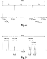
- the figure 4 represents such a division of the shared frequency resource MC into M ranges P m .
- M groups of passive components are defined, making it possible to modify a priori the oscillation frequency of a quartz oscillator.
- the range P m0 in which the said typical operating frequency TTOF n0 is located and the components of the group are determined. associated with this range are located in the terminal 10. Then, the value of at least one of these components is modified a posteriori so as to obtain an oscillation frequency substantially equal to the typical operation frequency TTOF n0 .
- the static configuration of a terminal 10 transmitting radio signals according to a sequence is carried out analogously by selecting, according to a random or pseudo-random number generator, several typical operating frequencies.
- a first random or pseudo-random number generator is considered for selecting a frequency range P m0 of the shared frequency resource MC, then a second random number generator for selecting a sequence of typical frequencies. operating all within the range P m0 .
- the present invention also relates to the telecommunications system 1 comprising at least one station 20 and a plurality of terminals 10.
- the frequency subbands used by the different terminals 10 are not necessarily disjointed. Therefore, some of said frequency subbands may overlap in whole or in part (e.g., if the frequency of operation TNOFR is greater than the spacing between typical frequencies of possible TTOF operation n ).
- the figure 5 schematically illustrates an example of statistical multiplexing of radio signals transmitted by different terminals in the shared MC frequency resource.
- the figure 5 illustrates in particular, in the right part, a case where two frequency sub-bands of width TNOFR, allocated to different terminals, overlap partially, and where the frequency drift makes it possible to avoid a collision between the radio signals emitted by these terminals.
- each terminal 10 is configured to independently determine when to transmit in a frequency sub-band that is statically assigned to it and / or with which power to transmit in this frequency sub-band.
- the station 20 preferably comprises means for detecting and decoding radio signals transmitted simultaneously by different terminals in different frequency sub-bands.
- radio signals having no synchronization, a priori, with the station 20 the latter must be able to detect any radio signal appearing in a multiplexing band MC, and to determine whether these radio signals correspond to radio signals emitted by terminals 10 or parasitic signals.
- the figure 6 schematically represents a preferred embodiment of the station 20. Note that the station 20 may also include other elements not shown on said figure 6 .
- the station 20 mainly comprises an analog module 200 and a digital module 210.
- the digital module 210 comprises in particular two analog / digital converters (A / D) 211 adapted to sample the output signals respectively of each anti-aliasing filter 207, for example with a sampling frequency substantially equal to the frequency multiplexing width MCB.
- a / D analog / digital converters
- the output signals of the A / D converters 211 respectively correspond to the real part and to the imaginary part of a complex signal designated by S T.
- the digital module 210 then comprises several functional blocks.
- the digital module 210 comprises an FFT block 212, adapted to transpose the complex signal S T from the time domain to the frequency domain, so as to obtain a complex signal S F representative of the frequency spectrum of the complex signal S T.
- the digital module 210 then comprises a detector block 213, adapted to seek in the complex signal S F frequencies for which peaks of energy are obtained, which may correspond to the presence of a radio signal transmitted by a terminal 10.
- the station 20 does not necessarily know the frequencies used by the various terminals 10, in particular because the actual frequency of operation TROF of a terminal 10 can be very different from the typical frequency of operation TTOF of this terminal due to the frequency drift.
- the use of the FFT block 212 and the detector block 213 therefore makes it possible to determine whether terminals 10 are transmitting radio signals and, if necessary, to estimate their actual frequencies of operation TROF.
- the FFT block 212 must be adapted to provide a complex signal S F with a granularity in the frequency domain making it possible to detect a radio signal with a busy frequency width TOB.
- the minimum occupied frequency width TOB MIN is preferably considered.
- the FFT block 212 is for example configured to obtain frequency samples, in the frequency band ranging from 0 Hz to MCB, with a step equal to MCB / TOB MIN , for elementary frequencies 0, TOB MIN , 2 ⁇ TOB MIN , 3 ⁇ TOB MIN , ..., MCB - TOB MIN .
- the detector block 213 measures, for example, the energy for each elementary frequency.
- a criterion for detecting a signal transmitted by a terminal 10 is for example verified when the measured energy for an elementary frequency is greater than a predefined threshold.
- the sinusoidal signal of frequency F e0 is multiplied to the complex signal S T by means of a multiplier block 215. This multiplication makes it possible to reduce the signal, detected around the elementary frequency of value F e0 , around the zero frequency 0 Hz.
- the digital module 210 then comprises a low-pass filter block 216, with a cut-off frequency substantially equal to half the occupied frequency width TOB (ie TOB / 2). In the case where several widths frequency occupied are possible, it is considered preferably the maximum occupied frequency width TOB MAX (a cutoff frequency substantially equal to TOB MAX / 2).
- the digital module 210 then comprises a decoder block 217 adapted to extract the data transmitted by a terminal 10.
- the exact implementation of the decoding block 217 depends on a predefined protocol for formatting the data transmitted by the terminals 10, and sets means known to those skilled in the art.
- the detector block 213 can be made to detect a plurality of elementary frequencies that may correspond to signals transmitted by terminals 10.
- the detector block 213 may be required to detect a number Ns of such elementary frequencies.
- the variable local oscillator blocks 214, multiplier 215, low-pass filter 216 and decoder 217 are advantageously replicated Ns times in order to process in parallel the signals around each of the Ns elementary frequencies that can be used by a terminal 10 .
- the station 20 comprises means for frequency tracking the typical frequency of TTOF operation of a terminal 10, in order to follow the drift thereof.
- the station 20 comprises means of performing a filtering adapted around any typical frequency of TTOF operation processed.
- the present invention thus makes it possible to perform statistical multiplexing of the radio signals emitted by different terminals sharing the same frequency resource MC in a decentralized manner.
- the use of frequency synthesis means whose frequency drift is greater than the instantaneous spectral width TOB of the radio signals emitted by the terminal 10 makes it possible to obtain statistical frequency multiplexing.
- the terminals 10 are advantageously configured so static from the factory to transmit radio signals in a single predefined frequency subband, or according to a single predefined sequence of frequency subbands.
- the typical frequencies of TTOF operation n are allocated in a substantially random manner, which also makes it possible to obtain statistical frequency multiplexing of the different radioelectric signals.
- Such an approach may be referred to as FSFDMA for "Forced Statistical FDMA".
- the invention does not require temporal and frequency synchronization of the terminals 10 with each other and with the station 20.
- terminals 10 it is possible to produce terminals 10 according to the invention at low cost, which makes the invention particularly suitable for low-rate systems, such as sensor networks, for example systems employing signals radio whose width of the instantaneous frequency spectrum is between 5 Hz and 5 kHz, or even preferably between 5 Hz and 500 Hz.
- the telecommunications system according to the invention is at the service of the terminals 10 insofar as they decide when and with what power to transmit, and to the extent that they are equipped with synthesis means such frequency drift is much greater than the occupied frequency width TOB.
- the station 20 generally does not know in advance the time at which each terminal 10 plans to transmit and does not know in advance the frequency subband that will be used by each terminal 10 (plus particularly the actual frequency of operation TROF of each terminal 10).
- the station 20 must therefore perform a search for radio signals potentially transmitted by terminals, and this throughout the multiplexing band MC.
Landscapes
- Engineering & Computer Science (AREA)
- Computer Networks & Wireless Communication (AREA)
- Signal Processing (AREA)
- Mobile Radio Communication Systems (AREA)
- Cable Transmission Systems, Equalization Of Radio And Reduction Of Echo (AREA)
Claims (15)
- Endgerät (10), das Mittel zum Übertragen von Daten in Richtung einer Station (20) in der Form von Funksignalen umfasst, wobei die Funksignale unter Verwendung einer Frequenzressource übertragen werden, die von einer Vielzahl von Endgeräten (10) gemeinsam genutzt wird, dadurch gekennzeichnet, dass das Endgerät dafür konfiguriert ist, Funksignale zu senden, deren momentanes Frequenzspektrum von einer Breite (TOB) ist, die mindestens fünfmal kleiner ist als eine Betriebsfrequenzbreite (TNOFR) des Endgeräts, wobei die Betriebsfrequenzbreite der Frequenzbreite entspricht, die von einem Funksignal im Laufe der Zeit effektiv belegt wird, unter Berücksichtigung der Breite des momentanen Frequenzspektrums der vom Endgerät gesendeten Funksignale und einer Frequenzabweichung eines Frequenzsynthesemittels des Endgeräts, und die im Wesentlichen gleich der Breite des momentanen Frequenzspektrums (TOB) ist, zu der die Frequenzabweichung des Frequenzsynthesemittels des Endgeräts hinzugefügt wird.
- Endgerät (10) nach Anspruch 1, dadurch gekennzeichnet, dass es in statischer Weise konfiguriert ist, um Funksignale in einem einzelnen vordefinierten Teilfrequenzband der Frequenzressource, oder nach einer einzelnen vordefinierten Sequenz von Teilfrequenzbändern der Frequenzressource zu übertragen.
- Endgerät (10) nach einem der Ansprüche 1 bis 2, dadurch gekennzeichnet, dass des dafür konfiguriert ist, in autonomer Weise zu ermitteln, wann in einem Teilfrequenzband der gemeinsam genutzten Frequenzressource gesendet werden soll.
- Endgerät (10) nach einem der vorstehenden Ansprüche, dadurch gekennzeichnet, dass es dafür konfiguriert ist, in autonomer Weise zu ermitteln, mit welcher Leistung Funksignale in einem Teilfrequenzband der gemeinsam genutzten Frequenzressource gesendet werden sollen.
- Endgerät (10) nach einem der vorstehenden Ansprüche, dadurch gekennzeichnet, dass die Funksignale Signale sind, die zuvor mittels eines Spreizcodes gespreizt wurden, wobei das Endgerät vorzugsweise in statischer Weise konfiguriert ist, um einen einzelnen vordefinierten Spreizcode oder eine vordefinierte Sequenz von Spreizcodes zu verwenden.
- Endgerät (10) nach einem der vorstehenden Ansprüche, dadurch gekennzeichnet, dass das momentane Frequenzspektrum der vom Endgerät gesendeten Funksignale von einer Breite (TOB) ist, die mindestens hundertmal kleiner ist als die Betriebsfrequenzbreite (TNOFR) des Endgeräts.
- Telekommunikationssystem (1), dadurch gekennzeichnet, dass es umfasst:- eine Vielzahl von Endgeräten (10) gemäß einem der vorstehenden Ansprüche,- mindestens eine Station (20), die Mittel zum Erkennen und zum Decodieren von Funksignalen umfasst, die gleichzeitig in verschiedenen Teilfrequenzbändern der gemeinsam genutzten Frequenzressource gesendet werden.
- System (1) nach Anspruch 7, dadurch gekennzeichnet, dass die Station (20) einen FFT-Block (212) umfasst, der dazu ausgebildet ist, ein Frequenzspektrum in der gemeinsam genutzten Frequenzressource zu ermitteln, und einen Detektorblock (213), der dazu ausgebildet ist, mindestens eine Energiespitze in dem ermittelten Frequenzspektrum zu suchen, die einem von einem Endgerät (10) gesendeten Funksignal entsprechen kann.
- Verfahren zum Verwenden einer Frequenzressource, die von einer Vielzahl von Endgeräten (10) gemeinsam genutzt wird, um Daten in der Form von Funksignalen an mindestens eine Station (20) zu senden, dadurch gekennzeichnet, dass jedes Endgerät (10) Funksignale sendet, deren momentanes Frequenzspektrum von einer Breite (TOB) ist, die mindestens fünfmal kleiner ist als eine Betriebsfrequenzbreite (TNOFR) des Endgeräts, wobei die Betriebsfrequenzbreite der Frequenzbreite entspricht, die von einem Funksignal im Laufe der Zeit effektiv belegt wird, unter Berücksichtigung der Breite des momentanen Frequenzspektrums der vom Endgerät gesendeten Funksignale und einer Frequenzabweichung eines Frequenzsynthesemittels des Endgeräts, und die im Wesentlichen gleich der Breite des momentanen Frequenzspektrums (TOB) ist, zu der die Frequenzabweichung des Frequenzsynthesemittels des Endgeräts hinzugefügt wird.
- Verwendungsverfahren nach Anspruch 9, dadurch gekennzeichnet, dass jedes Endgerät zuvor in statischer Weise konfiguriert wird, um Funksignale in einem einzelnen vordefinierten Teilfrequenzband der Frequenzressource, oder nach einer einzelnen vordefinierten Sequenz von Teilfrequenzbändern der Frequenzressource zu senden.
- Verwendungsverfahren nach einem der Ansprüche 9 bis 10, dadurch gekennzeichnet, dass jedes Endgerät (10) in autonomer Weise ermittelt, wann in einem Teilfrequenzband der gemeinsam genutzten Frequenzressource gesendet werden soll.
- Verwendungsverfahren nach einem der Ansprüche 9 bis 11, dadurch gekennzeichnet, dass jedes Endgerät (10) in autonomer Weise ermittelt, mit welcher Leistung Funksignale in einem Teilfrequenzband der gemeinsam genutzten Frequenzressource gesendet werden sollen.
- Verwendungsverfahren nach einem der Ansprüche 9 bis 12, dadurch gekennzeichnet, dass jedes Endgerät (10) Funksignale sendet, deren momentanes Frequenzspektrum von einer Breite (TOB) ist, die mindestens hundertmal kleiner ist als die Betriebsfrequenzbreite (TNOFR) des Endgeräts.
- Verfahren zur Herstellung von Telekommunikationsendgeräten (10), die dazu vorgesehen sind, eine gemeinsam genutzte Frequenzressource zu verwenden, das für die Herstellung jedes Endgeräts (10) die Schritte umfasst des:- Erhaltens von mindestens einer Zufalls- oder Pseudozufallszahl, abhängig von mindestens einem Generator von Zufalls- oder Pseudozufallszahlen, die nach einem im Wesentlichen einheitlichen Gesetz verteilt sind,- Ermittelns eines Teilfrequenzbandes der Frequenzressource oder einer Sequenz von Teilfrequenzbändern der Frequenzressource abhängig von der mindestens einen Zufalls- oder Pseudozufallszahl,- Ausstattens des Endgeräts (10) mit einem Frequenzsynthesemittel, das in statischer Weise konfiguriert ist, um Funksignale nur in dem Teilfrequenzband oder nur nach der vordefinierten Sequenz von Teilfrequenzbändern der Frequenzressource zu übertragen, die abhängig von der mindestens einen Zufalls- oder Pseudozufallszahl ermittelt wurde, und um Funksignale zu übertragen, deren momentanes Frequenzspektrum von einer Breite (TOB) ist, die mindestens fünfmal kleiner ist als eine Betriebsfrequenzbreite (TNOFR) des Endgeräts, wobei die Betriebsfrequenzbreite der Frequenzbreite entspricht, die von einem Funksignal im Laufe der Zeit effektiv belegt wird, unter Berücksichtigung der Breite des momentanen Frequenzspektrums der vom Endgerät gesendeten Funksignale und einer Frequenzabweichung des Frequenzsynthesemittels des Endgeräts, und die im Wesentlichen gleich der Breite des momentanen Frequenzspektrums (TOB) ist, zu der die Frequenzabweichung des Frequenzsynthesemittels des Endgeräts hinzugefügt wird.
- Herstellungsverfahren nach Anspruch14, dadurch gekennzeichnet, dass der Schritt des Ermittelns des Teilfrequenzbandes der Frequenzressource oder der Sequenz von Teilfrequenzbändern der Frequenzressource, das/die einem Endgerät (10) in statischer Weise zugewiesen werden soll, mindestens einen der folgenden Schritte umfasst:- Auswählen eines Fraktional-Divisionswertes für einen Fraktional-Frequenzsynthetisierer,- Auswählen eines Steuerspannungswertes, der an einen spannungsgesteuerten Oszillator angelegt werden soll,- Auswählen einer Gruppe von Komponenten, die in das Endgerät (10) integriert werden sollen, um die Oszillationsfrequenz eines Oszillators zu modifizieren,- Auswählen eines physischen Umbaus, der an mindestens einer Komponente ausgeführt werden soll, um die Oszillationsfrequenz eines Oszillators zu modifizieren.
Applications Claiming Priority (3)
| Application Number | Priority Date | Filing Date | Title |
|---|---|---|---|
| FR1054509A FR2961054A1 (fr) | 2010-06-08 | 2010-06-08 | Procede d'utilisation d'une ressource frequentielle partagee, procede de configuration de terminaux, terminaux et systeme de telecommunications |
| FR1056703A FR2961046B1 (fr) | 2010-06-08 | 2010-08-20 | Procede d'utilisation d'une ressource frequentielle partagee, procede de configuration de terminaux, terminaux et systeme de telecommunications |
| PCT/EP2011/059538 WO2011154466A1 (fr) | 2010-06-08 | 2011-06-08 | Procédé d'utilisation d'une ressource fréquentielle partagée, procédé de fabrication de terminaux, terminaux et système de télécommunications |
Publications (2)
| Publication Number | Publication Date |
|---|---|
| EP2580882A1 EP2580882A1 (de) | 2013-04-17 |
| EP2580882B1 true EP2580882B1 (de) | 2018-09-05 |
Family
ID=43502515
Family Applications (1)
| Application Number | Title | Priority Date | Filing Date |
|---|---|---|---|
| EP11724212.3A Active EP2580882B1 (de) | 2010-06-08 | 2011-06-08 | Verfahren zur verwendung einer geteilten frequenzressource, verfahren zur herstellung von endgeräten, endgeräte und telekommunikationssystem |
Country Status (8)
| Country | Link |
|---|---|
| US (1) | US9049732B2 (de) |
| EP (1) | EP2580882B1 (de) |
| JP (1) | JP5736450B2 (de) |
| AU (1) | AU2011263754B2 (de) |
| BR (1) | BR112012031246B1 (de) |
| FR (2) | FR2961054A1 (de) |
| RU (1) | RU2559834C2 (de) |
| WO (1) | WO2011154466A1 (de) |
Families Citing this family (18)
| Publication number | Priority date | Publication date | Assignee | Title |
|---|---|---|---|---|
| FR2992506B1 (fr) | 2012-06-25 | 2014-06-20 | Sigfox Wireless | Procede d'authentification de paquets de donnees recus par une station d'un systeme de telecommunications numerique |
| FR2993119B1 (fr) | 2012-07-05 | 2014-08-08 | Sigfox Wireless | Procede de recherche d'un signal utile dans une bande de multiplexage |
| FR3016107B1 (fr) | 2013-12-26 | 2017-03-24 | Grdf | Procede de transmission de donnees par liaison radiofrequence dans une installation de telereleve |
| FR3038172B1 (fr) | 2015-06-26 | 2018-06-29 | Sigfox | Procede de determination du decalage temporel existant entre les horloges des stations de base d'un reseau de communication |
| CN105187092B (zh) * | 2015-08-10 | 2018-01-16 | 广东欧珀移动通信有限公司 | 一种减少移动通信的干扰信号的方法和装置 |
| WO2017050389A1 (en) | 2015-09-25 | 2017-03-30 | Huawei Technologies Co., Ltd. | Communication protocol for low energy communication links |
| KR101811221B1 (ko) * | 2016-02-17 | 2017-12-21 | 주식회사 이노와이어리스 | 신호 분석기의 wcdma 신호 타이밍 오프셋 처리 방법 |
| FR3051612B1 (fr) * | 2016-05-17 | 2018-05-11 | Centre National D'etudes Spatiales (Cnes) | Procede et systeme de telecommunication |
| US10659101B2 (en) | 2016-06-08 | 2020-05-19 | Sony Semiconductor Solutions Corporation | Information processing device and method, transmitting device and method, and receiving device and method |
| US10257009B2 (en) | 2016-12-30 | 2019-04-09 | Waviot Integrated Systems, Llc | Method for multichannel signal search and demodulation and technique to demodulate and detect DBPSK FDMA ultra-narrow band signal |
| WO2018126204A1 (en) | 2016-12-30 | 2018-07-05 | Waviot Integrated Systems, Llc | Simultaneous confirmation of many messages in lpwan & frequency correction for data transmission |
| US10326556B2 (en) | 2016-12-30 | 2019-06-18 | Waviot Integrated Systems, Llc | Method and system of frequency correction in LPWAN networks |
| US10419063B2 (en) | 2016-12-30 | 2019-09-17 | Waviot Integrated Systems, Llc | Method and system for receiving telemetry messages over RF channel |
| EP3462762A1 (de) * | 2017-09-29 | 2019-04-03 | Intel Corporation | Zugangspunktvorrichtung und verfahren zur steuerung eines dezentralisierten drahtlosen netzwerks |
| US20210273848A1 (en) | 2017-11-17 | 2021-09-02 | Thierry Fayard | Alert and disaster management system and method for operating such a system |
| WO2020040810A1 (en) * | 2018-08-20 | 2020-02-27 | Waviot Integrated Systems Llc | Method and system for receiving telemetry messages over rf channel |
| CN115189781B (zh) * | 2022-06-02 | 2024-04-09 | 中国信息通信研究院 | 一种仪器仪表占用带宽的校准系统及方法 |
| US12242299B2 (en) | 2022-11-02 | 2025-03-04 | Rohde & Schwarz Gmbh & Co. Kg | Signal synthesizer circuit, signal generator device, and signal synthesis method |
Family Cites Families (35)
| Publication number | Priority date | Publication date | Assignee | Title |
|---|---|---|---|---|
| US4345334A (en) * | 1977-05-05 | 1982-08-17 | American Optical Corporation | Reduced-cross talk telemetry system and method of manufacture thereof |
| US4298985A (en) * | 1979-12-31 | 1981-11-03 | The United States Of America As Represented By The Secretary Of The Army | Digital filter bank detector |
| US4414661A (en) * | 1981-07-02 | 1983-11-08 | Trancom Ab | Apparatus for communicating with a fleet of vehicles |
| US4896369A (en) * | 1984-12-28 | 1990-01-23 | Harris Corporation | Optimal satellite TWT power allocation process for achieving requested availability and maintaining stability in ALPC-type networks |
| US4878035A (en) * | 1988-05-27 | 1989-10-31 | Wavetek Rf Products, Inc. | Hybrid frequency shift keying modulator and method |
| JP2754788B2 (ja) * | 1989-09-29 | 1998-05-20 | 日立電線株式会社 | 無線テレメータ単向式伝送方式 |
| US5184350A (en) * | 1991-04-17 | 1993-02-02 | Raytheon Company | Telephone communication system having an enhanced timing circuit |
| US5295138A (en) * | 1992-04-21 | 1994-03-15 | Northwest Starscon Limited Partnership | Apparatus and method for optimal frequency planning in frequency division multiplexing transmissions |
| US5840040A (en) * | 1992-12-18 | 1998-11-24 | The Regents Of The University Of California | Encephalolexianalyzer |
| JPH0799458A (ja) * | 1993-09-29 | 1995-04-11 | Uniden Corp | Scpc信号受信機能付き衛星放送受信機 |
| US5838226A (en) * | 1996-02-07 | 1998-11-17 | Lutron Electronics Co.Inc. | Communication protocol for transmission system for controlling and determining the status of electrical devices from remote locations |
| EP0810750B1 (de) * | 1996-05-30 | 2005-07-13 | Matsushita Electric Industrial Co., Ltd. | Empfänger für digitalen Rundfunk |
| US6370244B1 (en) * | 1998-04-03 | 2002-04-09 | Board Of Regents Of The University Of Texas System | Efficient digital ITU-compliant zero-buffering DTMF detection using the non-uniform discrete fourier transform |
| JP4045043B2 (ja) * | 1999-02-24 | 2008-02-13 | 本田技研工業株式会社 | レーダ装置 |
| US6560293B1 (en) * | 1999-05-04 | 2003-05-06 | 3Com Corporation | Apparatus and method for FM remodulation of envelope modulated data signals |
| US6731223B1 (en) * | 2000-01-15 | 2004-05-04 | Andrzej Partyka | Meshed telemetry system |
| US6546248B1 (en) * | 2000-02-10 | 2003-04-08 | Qualcomm, Incorporated | Method and apparatus for generating pilot strength measurement messages |
| US6366174B1 (en) * | 2000-02-21 | 2002-04-02 | Lexmark International, Inc. | Method and apparatus for providing a clock generation circuit for digitally controlled frequency or spread spectrum clocking |
| JP4415518B2 (ja) * | 2001-08-15 | 2010-02-17 | 横浜ゴム株式会社 | 送信機および無線送信システム |
| WO2005125249A1 (ja) * | 2004-06-18 | 2005-12-29 | Mitsubishi Denki Kabushiki Kaisha | 自律的セル形成方法 |
| KR20060006725A (ko) * | 2004-07-16 | 2006-01-19 | 삼성전자주식회사 | 향상된 상향링크 전용채널을 지원하는 이동통신시스템에서자율전송을 위한 파라미터 결정 방법 및 장치 |
| JP4592358B2 (ja) * | 2004-08-31 | 2010-12-01 | 株式会社エヌ・ティ・ティ・ドコモ | 移動通信システム及び移動通信方法 |
| US8395664B2 (en) * | 2006-09-13 | 2013-03-12 | Smartvue Corp. | Wireless surveillance system and method for 3-D visualization and user-controlled analytics of captured data |
| US7804850B2 (en) * | 2004-10-01 | 2010-09-28 | Nokia Corporation | Slow MAC-e for autonomous transmission in high speed uplink packet access (HSUPA) along with service specific transmission time control |
| KR100681260B1 (ko) * | 2004-10-07 | 2007-02-09 | 삼성전자주식회사 | 전력 스펙트럼 기반의 속도 추정에 의한 속도 정합형 채널추정방법 및 이를 이용한 이동통신 단말의 복조기 |
| RU2289202C2 (ru) * | 2004-11-23 | 2006-12-10 | Зао "Элвиис" | Многоканальный перепрограммируемый цифровой приемный тракт |
| CN100590982C (zh) * | 2005-01-06 | 2010-02-17 | 株式会社村田制作所 | 无线接收机 |
| US7787846B1 (en) * | 2005-09-08 | 2010-08-31 | Page Edward A | Ultra low power RF link |
| US8098720B2 (en) * | 2006-10-06 | 2012-01-17 | Stmicroelectronics S.R.L. | Method and apparatus for suppressing adjacent channel interference and multipath propagation signals and radio receiver using said apparatus |
| US9014047B2 (en) * | 2007-07-10 | 2015-04-21 | Level 3 Communications, Llc | System and method for aggregating and reporting network traffic data |
| US8345238B2 (en) * | 2008-02-04 | 2013-01-01 | General Photonics Corporation | Measuring optical spectral property of light based on polarization analysis |
| US20090281435A1 (en) * | 2008-05-07 | 2009-11-12 | Motorola, Inc. | Method and apparatus for robust heart rate sensing |
| US8189547B2 (en) * | 2008-10-21 | 2012-05-29 | Symbol Technologies, Inc. | Self-configuration of wireless access devices in a wireless network environment |
| BRPI1006912A2 (pt) * | 2009-01-06 | 2016-02-16 | Directv Group Inc | estimação de deriva de frequência para unidade externa de baixo custo |
| JP2011154515A (ja) * | 2010-01-27 | 2011-08-11 | Sharp Corp | 無線テレメータシステム |
-
2010
- 2010-06-08 FR FR1054509A patent/FR2961054A1/fr active Pending
- 2010-08-20 FR FR1056703A patent/FR2961046B1/fr not_active Expired - Fee Related
-
2011
- 2011-06-08 RU RU2012156245/07A patent/RU2559834C2/ru active
- 2011-06-08 JP JP2013513682A patent/JP5736450B2/ja active Active
- 2011-06-08 US US13/702,206 patent/US9049732B2/en active Active
- 2011-06-08 WO PCT/EP2011/059538 patent/WO2011154466A1/fr not_active Ceased
- 2011-06-08 BR BR112012031246-4A patent/BR112012031246B1/pt active IP Right Grant
- 2011-06-08 EP EP11724212.3A patent/EP2580882B1/de active Active
- 2011-06-08 AU AU2011263754A patent/AU2011263754B2/en active Active
Also Published As
| Publication number | Publication date |
|---|---|
| US20130142191A1 (en) | 2013-06-06 |
| AU2011263754B2 (en) | 2016-04-14 |
| AU2011263754A1 (en) | 2013-01-10 |
| FR2961046B1 (fr) | 2013-06-07 |
| RU2559834C2 (ru) | 2015-08-10 |
| BR112012031246B1 (pt) | 2021-09-28 |
| BR112012031246A2 (pt) | 2016-11-01 |
| WO2011154466A1 (fr) | 2011-12-15 |
| JP2013535132A (ja) | 2013-09-09 |
| RU2012156245A (ru) | 2014-07-20 |
| FR2961046A1 (fr) | 2011-12-09 |
| EP2580882A1 (de) | 2013-04-17 |
| FR2961054A1 (fr) | 2011-12-09 |
| US9049732B2 (en) | 2015-06-02 |
| JP5736450B2 (ja) | 2015-06-17 |
Similar Documents
| Publication | Publication Date | Title |
|---|---|---|
| WO2011154466A1 (fr) | Procédé d'utilisation d'une ressource fréquentielle partagée, procédé de fabrication de terminaux, terminaux et système de télécommunications | |
| EP1302016B1 (de) | Synchronisation der von mehreren einheiten ausgesendeten signale in einer basisstation, für fdma-kommunikationssysteme | |
| EP2732592B1 (de) | Verfahren und modul zur schätzung der frequenzverzerrung in einem system für digitale telekommunikation | |
| EP3171195B1 (de) | Verfahren zur lokalisierung einer bake | |
| EP4301079A2 (de) | Verfahren zum senden einer nachricht mit intra-prozeduralem frequenzsprung über ein endgerät eines kommunikationssystems mit slot-zugang | |
| FR3020531A1 (fr) | Dispositif et methode de determination du temps d'arrivee d'un signal uwb. | |
| EP3266256A1 (de) | Verfahren zur übertragung von daten zwischen einem endgerät und einem frequenzsynchronisierten zugangsnetzwerk auf einer uplink-nachricht von besagtem endgerät | |
| FR2995115A1 (fr) | Procedes d'emission et de reception de donnees dans un systeme de telecommunications numeriques | |
| EP3286938B1 (de) | Verfahren zum senden und empfangen eines rundfunksignals mit einem steuersignal und einem informationssignal | |
| EP1081855B1 (de) | Verfahren und vorrichtung zur synchronisation eines kommunikationsempfängers | |
| MC973A1 (fr) | Nouveau mode de radiolocalisation du du type hyperbolique à mesure de phase | |
| WO2014001708A1 (fr) | Procede d'authentification de paquets de donnees recus par une station d'un systeme de telecommunications numerique | |
| FR2782594A1 (fr) | Procede de mesure simultanee des caracteristiques de propagation d'une pluralite de canaux radioelectriques | |
| FR2854009A1 (fr) | Signal multiporteuse concu pour reduire les interferences cellulaires au sein d'un reseau de radiocommunication, procede de construction, procede de reception, recepteur et emetteur correspondants | |
| EP1303061B1 (de) | Telekommunikationssystem mit niedriger parasitärer elektromagnetischer Strahlung | |
| EP2146457A1 (de) | Zeitliches Synchronisierungsverfahren eines digitalen Signals, sowie entsprechende Vorrichtung und entsprechendes Computerprogrammprodukt. | |
| EP3918728B1 (de) | Drahtloses kommunikations-verfahren und system zwischen sendern und einem empfänger mittels einer relaisvorrichtung mit simultaner wiederholung | |
| FR3033105A1 (fr) | Procedes d'emission et de reception de messages descendants avec identification implicite de destinataires | |
| FR3134458A1 (fr) | Système de positionnement à segments de câble rayonnant | |
| FR2881010A1 (fr) | Procedes et dispositifs de diffusion et d'acces a une offre de service specifique a une zone geographique dans un reseau de telecommunications sans fil | |
| FR3034612A1 (fr) | Procede et systeme d'estimation d'une capacite de detection de messages dans une bande frequentielle | |
| CA2251630A1 (fr) | Procede de transmission de signaux numeriques par frequences correllees | |
| WO2010130915A1 (fr) | Scrutation de bande de radiocommunications | |
| CH326024A (fr) | Dispositif de réception | |
| EP1810414A1 (de) | Verfahren und einrichtung zum senden einer ultrabreitband-frequenz |
Legal Events
| Date | Code | Title | Description |
|---|---|---|---|
| PUAI | Public reference made under article 153(3) epc to a published international application that has entered the european phase |
Free format text: ORIGINAL CODE: 0009012 |
|
| 17P | Request for examination filed |
Effective date: 20121226 |
|
| AK | Designated contracting states |
Kind code of ref document: A1 Designated state(s): AL AT BE BG CH CY CZ DE DK EE ES FI FR GB GR HR HU IE IS IT LI LT LU LV MC MK MT NL NO PL PT RO RS SE SI SK SM TR |
|
| DAX | Request for extension of the european patent (deleted) | ||
| 17Q | First examination report despatched |
Effective date: 20160726 |
|
| STAA | Information on the status of an ep patent application or granted ep patent |
Free format text: STATUS: EXAMINATION IS IN PROGRESS |
|
| GRAP | Despatch of communication of intention to grant a patent |
Free format text: ORIGINAL CODE: EPIDOSNIGR1 |
|
| STAA | Information on the status of an ep patent application or granted ep patent |
Free format text: STATUS: GRANT OF PATENT IS INTENDED |
|
| INTG | Intention to grant announced |
Effective date: 20180323 |
|
| GRAS | Grant fee paid |
Free format text: ORIGINAL CODE: EPIDOSNIGR3 |
|
| GRAA | (expected) grant |
Free format text: ORIGINAL CODE: 0009210 |
|
| STAA | Information on the status of an ep patent application or granted ep patent |
Free format text: STATUS: THE PATENT HAS BEEN GRANTED |
|
| RAP1 | Party data changed (applicant data changed or rights of an application transferred) |
Owner name: SIGFOX |
|
| AK | Designated contracting states |
Kind code of ref document: B1 Designated state(s): AL AT BE BG CH CY CZ DE DK EE ES FI FR GB GR HR HU IE IS IT LI LT LU LV MC MK MT NL NO PL PT RO RS SE SI SK SM TR |
|
| REG | Reference to a national code |
Ref country code: GB Ref legal event code: FG4D Free format text: NOT ENGLISH |
|
| REG | Reference to a national code |
Ref country code: CH Ref legal event code: EP |
|
| REG | Reference to a national code |
Ref country code: AT Ref legal event code: REF Ref document number: 1039098 Country of ref document: AT Kind code of ref document: T Effective date: 20180915 |
|
| REG | Reference to a national code |
Ref country code: DE Ref legal event code: R096 Ref document number: 602011051755 Country of ref document: DE |
|
| REG | Reference to a national code |
Ref country code: IE Ref legal event code: FG4D Free format text: LANGUAGE OF EP DOCUMENT: FRENCH |
|
| REG | Reference to a national code |
Ref country code: SE Ref legal event code: TRGR |
|
| REG | Reference to a national code |
Ref country code: NL Ref legal event code: MP Effective date: 20180905 |
|
| REG | Reference to a national code |
Ref country code: LT Ref legal event code: MG4D |
|
| PG25 | Lapsed in a contracting state [announced via postgrant information from national office to epo] |
Ref country code: GR Free format text: LAPSE BECAUSE OF FAILURE TO SUBMIT A TRANSLATION OF THE DESCRIPTION OR TO PAY THE FEE WITHIN THE PRESCRIBED TIME-LIMIT Effective date: 20181206 Ref country code: NO Free format text: LAPSE BECAUSE OF FAILURE TO SUBMIT A TRANSLATION OF THE DESCRIPTION OR TO PAY THE FEE WITHIN THE PRESCRIBED TIME-LIMIT Effective date: 20181205 Ref country code: BG Free format text: LAPSE BECAUSE OF FAILURE TO SUBMIT A TRANSLATION OF THE DESCRIPTION OR TO PAY THE FEE WITHIN THE PRESCRIBED TIME-LIMIT Effective date: 20181205 Ref country code: RS Free format text: LAPSE BECAUSE OF FAILURE TO SUBMIT A TRANSLATION OF THE DESCRIPTION OR TO PAY THE FEE WITHIN THE PRESCRIBED TIME-LIMIT Effective date: 20180905 Ref country code: LT Free format text: LAPSE BECAUSE OF FAILURE TO SUBMIT A TRANSLATION OF THE DESCRIPTION OR TO PAY THE FEE WITHIN THE PRESCRIBED TIME-LIMIT Effective date: 20180905 |
|
| REG | Reference to a national code |
Ref country code: AT Ref legal event code: MK05 Ref document number: 1039098 Country of ref document: AT Kind code of ref document: T Effective date: 20180905 |
|
| PG25 | Lapsed in a contracting state [announced via postgrant information from national office to epo] |
Ref country code: AL Free format text: LAPSE BECAUSE OF FAILURE TO SUBMIT A TRANSLATION OF THE DESCRIPTION OR TO PAY THE FEE WITHIN THE PRESCRIBED TIME-LIMIT Effective date: 20180905 Ref country code: LV Free format text: LAPSE BECAUSE OF FAILURE TO SUBMIT A TRANSLATION OF THE DESCRIPTION OR TO PAY THE FEE WITHIN THE PRESCRIBED TIME-LIMIT Effective date: 20180905 Ref country code: HR Free format text: LAPSE BECAUSE OF FAILURE TO SUBMIT A TRANSLATION OF THE DESCRIPTION OR TO PAY THE FEE WITHIN THE PRESCRIBED TIME-LIMIT Effective date: 20180905 |
|
| PG25 | Lapsed in a contracting state [announced via postgrant information from national office to epo] |
Ref country code: EE Free format text: LAPSE BECAUSE OF FAILURE TO SUBMIT A TRANSLATION OF THE DESCRIPTION OR TO PAY THE FEE WITHIN THE PRESCRIBED TIME-LIMIT Effective date: 20180905 Ref country code: PL Free format text: LAPSE BECAUSE OF FAILURE TO SUBMIT A TRANSLATION OF THE DESCRIPTION OR TO PAY THE FEE WITHIN THE PRESCRIBED TIME-LIMIT Effective date: 20180905 Ref country code: IS Free format text: LAPSE BECAUSE OF FAILURE TO SUBMIT A TRANSLATION OF THE DESCRIPTION OR TO PAY THE FEE WITHIN THE PRESCRIBED TIME-LIMIT Effective date: 20190105 Ref country code: ES Free format text: LAPSE BECAUSE OF FAILURE TO SUBMIT A TRANSLATION OF THE DESCRIPTION OR TO PAY THE FEE WITHIN THE PRESCRIBED TIME-LIMIT Effective date: 20180905 Ref country code: NL Free format text: LAPSE BECAUSE OF FAILURE TO SUBMIT A TRANSLATION OF THE DESCRIPTION OR TO PAY THE FEE WITHIN THE PRESCRIBED TIME-LIMIT Effective date: 20180905 Ref country code: IT Free format text: LAPSE BECAUSE OF FAILURE TO SUBMIT A TRANSLATION OF THE DESCRIPTION OR TO PAY THE FEE WITHIN THE PRESCRIBED TIME-LIMIT Effective date: 20180905 Ref country code: RO Free format text: LAPSE BECAUSE OF FAILURE TO SUBMIT A TRANSLATION OF THE DESCRIPTION OR TO PAY THE FEE WITHIN THE PRESCRIBED TIME-LIMIT Effective date: 20180905 Ref country code: CZ Free format text: LAPSE BECAUSE OF FAILURE TO SUBMIT A TRANSLATION OF THE DESCRIPTION OR TO PAY THE FEE WITHIN THE PRESCRIBED TIME-LIMIT Effective date: 20180905 Ref country code: AT Free format text: LAPSE BECAUSE OF FAILURE TO SUBMIT A TRANSLATION OF THE DESCRIPTION OR TO PAY THE FEE WITHIN THE PRESCRIBED TIME-LIMIT Effective date: 20180905 |
|
| PG25 | Lapsed in a contracting state [announced via postgrant information from national office to epo] |
Ref country code: SM Free format text: LAPSE BECAUSE OF FAILURE TO SUBMIT A TRANSLATION OF THE DESCRIPTION OR TO PAY THE FEE WITHIN THE PRESCRIBED TIME-LIMIT Effective date: 20180905 Ref country code: PT Free format text: LAPSE BECAUSE OF FAILURE TO SUBMIT A TRANSLATION OF THE DESCRIPTION OR TO PAY THE FEE WITHIN THE PRESCRIBED TIME-LIMIT Effective date: 20190105 Ref country code: SK Free format text: LAPSE BECAUSE OF FAILURE TO SUBMIT A TRANSLATION OF THE DESCRIPTION OR TO PAY THE FEE WITHIN THE PRESCRIBED TIME-LIMIT Effective date: 20180905 |
|
| REG | Reference to a national code |
Ref country code: DE Ref legal event code: R097 Ref document number: 602011051755 Country of ref document: DE |
|
| PLBE | No opposition filed within time limit |
Free format text: ORIGINAL CODE: 0009261 |
|
| STAA | Information on the status of an ep patent application or granted ep patent |
Free format text: STATUS: NO OPPOSITION FILED WITHIN TIME LIMIT |
|
| PG25 | Lapsed in a contracting state [announced via postgrant information from national office to epo] |
Ref country code: DK Free format text: LAPSE BECAUSE OF FAILURE TO SUBMIT A TRANSLATION OF THE DESCRIPTION OR TO PAY THE FEE WITHIN THE PRESCRIBED TIME-LIMIT Effective date: 20180905 |
|
| 26N | No opposition filed |
Effective date: 20190606 |
|
| PG25 | Lapsed in a contracting state [announced via postgrant information from national office to epo] |
Ref country code: SI Free format text: LAPSE BECAUSE OF FAILURE TO SUBMIT A TRANSLATION OF THE DESCRIPTION OR TO PAY THE FEE WITHIN THE PRESCRIBED TIME-LIMIT Effective date: 20180905 |
|
| PG25 | Lapsed in a contracting state [announced via postgrant information from national office to epo] |
Ref country code: MC Free format text: LAPSE BECAUSE OF FAILURE TO SUBMIT A TRANSLATION OF THE DESCRIPTION OR TO PAY THE FEE WITHIN THE PRESCRIBED TIME-LIMIT Effective date: 20180905 |
|
| REG | Reference to a national code |
Ref country code: CH Ref legal event code: PL |
|
| REG | Reference to a national code |
Ref country code: BE Ref legal event code: MM Effective date: 20190630 |
|
| PG25 | Lapsed in a contracting state [announced via postgrant information from national office to epo] |
Ref country code: TR Free format text: LAPSE BECAUSE OF FAILURE TO SUBMIT A TRANSLATION OF THE DESCRIPTION OR TO PAY THE FEE WITHIN THE PRESCRIBED TIME-LIMIT Effective date: 20180905 |
|
| PG25 | Lapsed in a contracting state [announced via postgrant information from national office to epo] |
Ref country code: IE Free format text: LAPSE BECAUSE OF NON-PAYMENT OF DUE FEES Effective date: 20190608 |
|
| PG25 | Lapsed in a contracting state [announced via postgrant information from national office to epo] |
Ref country code: CH Free format text: LAPSE BECAUSE OF NON-PAYMENT OF DUE FEES Effective date: 20190630 Ref country code: LI Free format text: LAPSE BECAUSE OF NON-PAYMENT OF DUE FEES Effective date: 20190630 Ref country code: LU Free format text: LAPSE BECAUSE OF NON-PAYMENT OF DUE FEES Effective date: 20190608 Ref country code: BE Free format text: LAPSE BECAUSE OF NON-PAYMENT OF DUE FEES Effective date: 20190630 |
|
| PG25 | Lapsed in a contracting state [announced via postgrant information from national office to epo] |
Ref country code: CY Free format text: LAPSE BECAUSE OF FAILURE TO SUBMIT A TRANSLATION OF THE DESCRIPTION OR TO PAY THE FEE WITHIN THE PRESCRIBED TIME-LIMIT Effective date: 20180905 |
|
| PG25 | Lapsed in a contracting state [announced via postgrant information from national office to epo] |
Ref country code: MT Free format text: LAPSE BECAUSE OF FAILURE TO SUBMIT A TRANSLATION OF THE DESCRIPTION OR TO PAY THE FEE WITHIN THE PRESCRIBED TIME-LIMIT Effective date: 20180905 Ref country code: HU Free format text: LAPSE BECAUSE OF FAILURE TO SUBMIT A TRANSLATION OF THE DESCRIPTION OR TO PAY THE FEE WITHIN THE PRESCRIBED TIME-LIMIT; INVALID AB INITIO Effective date: 20110608 |
|
| PG25 | Lapsed in a contracting state [announced via postgrant information from national office to epo] |
Ref country code: MK Free format text: LAPSE BECAUSE OF FAILURE TO SUBMIT A TRANSLATION OF THE DESCRIPTION OR TO PAY THE FEE WITHIN THE PRESCRIBED TIME-LIMIT Effective date: 20180905 |
|
| REG | Reference to a national code |
Ref country code: GB Ref legal event code: 732E Free format text: REGISTERED BETWEEN 20240125 AND 20240131 |
|
| REG | Reference to a national code |
Ref country code: FI Ref legal event code: PCE Owner name: UNABIZ |
|
| REG | Reference to a national code |
Ref country code: DE Ref legal event code: R081 Ref document number: 602011051755 Country of ref document: DE Owner name: UNABIZ SAS, FR Free format text: FORMER OWNER: SIGFOX, LABEGE, FR |
|
| PGFP | Annual fee paid to national office [announced via postgrant information from national office to epo] |
Ref country code: FI Payment date: 20250626 Year of fee payment: 15 |
|
| PGFP | Annual fee paid to national office [announced via postgrant information from national office to epo] |
Ref country code: DE Payment date: 20250627 Year of fee payment: 15 |
|
| PGFP | Annual fee paid to national office [announced via postgrant information from national office to epo] |
Ref country code: GB Payment date: 20250630 Year of fee payment: 15 |
|
| PGFP | Annual fee paid to national office [announced via postgrant information from national office to epo] |
Ref country code: FR Payment date: 20250619 Year of fee payment: 15 |
|
| PGFP | Annual fee paid to national office [announced via postgrant information from national office to epo] |
Ref country code: SE Payment date: 20250630 Year of fee payment: 15 |