EP2581177A2 - Procédé de commande de robot - Google Patents
Procédé de commande de robot Download PDFInfo
- Publication number
- EP2581177A2 EP2581177A2 EP12186961.4A EP12186961A EP2581177A2 EP 2581177 A2 EP2581177 A2 EP 2581177A2 EP 12186961 A EP12186961 A EP 12186961A EP 2581177 A2 EP2581177 A2 EP 2581177A2
- Authority
- EP
- European Patent Office
- Prior art keywords
- robot
- manipulator
- reference point
- values
- orientation
- Prior art date
- Legal status (The legal status is an assumption and is not a legal conclusion. Google has not performed a legal analysis and makes no representation as to the accuracy of the status listed.)
- Granted
Links
Images


Classifications
-
- B—PERFORMING OPERATIONS; TRANSPORTING
- B25—HAND TOOLS; PORTABLE POWER-DRIVEN TOOLS; MANIPULATORS
- B25J—MANIPULATORS; CHAMBERS PROVIDED WITH MANIPULATION DEVICES
- B25J9/00—Program-controlled manipulators
- B25J9/16—Program controls
-
- B—PERFORMING OPERATIONS; TRANSPORTING
- B25—HAND TOOLS; PORTABLE POWER-DRIVEN TOOLS; MANIPULATORS
- B25J—MANIPULATORS; CHAMBERS PROVIDED WITH MANIPULATION DEVICES
- B25J9/00—Program-controlled manipulators
- B25J9/16—Program controls
- B25J9/1615—Program controls characterised by special kind of manipulator, e.g. planar, scara, gantry, cantilever, space, closed chain, passive/active joints and tendon driven manipulators
- B25J9/162—Mobile manipulator, movable base with manipulator arm mounted on it
-
- B—PERFORMING OPERATIONS; TRANSPORTING
- B25—HAND TOOLS; PORTABLE POWER-DRIVEN TOOLS; MANIPULATORS
- B25J—MANIPULATORS; CHAMBERS PROVIDED WITH MANIPULATION DEVICES
- B25J9/00—Program-controlled manipulators
- B25J9/06—Program-controlled manipulators characterised by multi-articulated arms
-
- G—PHYSICS
- G05—CONTROLLING; REGULATING
- G05B—CONTROL OR REGULATING SYSTEMS IN GENERAL; FUNCTIONAL ELEMENTS OF SUCH SYSTEMS; MONITORING OR TESTING ARRANGEMENTS FOR SUCH SYSTEMS OR ELEMENTS
- G05B19/00—Program-control systems
- G05B19/02—Program-control systems electric
- G05B19/18—Numerical control [NC], i.e. automatically operating machines, in particular machine tools, e.g. in a manufacturing environment, so as to execute positioning, movement or co-ordinated operations by means of program data in numerical form
- G05B19/402—Numerical control [NC], i.e. automatically operating machines, in particular machine tools, e.g. in a manufacturing environment, so as to execute positioning, movement or co-ordinated operations by means of program data in numerical form characterised by control arrangements for positioning, e.g. centring a tool relative to a hole in the workpiece, additional detection means to correct position
-
- G—PHYSICS
- G05—CONTROLLING; REGULATING
- G05B—CONTROL OR REGULATING SYSTEMS IN GENERAL; FUNCTIONAL ELEMENTS OF SUCH SYSTEMS; MONITORING OR TESTING ARRANGEMENTS FOR SUCH SYSTEMS OR ELEMENTS
- G05B2219/00—Program-control systems
- G05B2219/30—Nc systems
- G05B2219/40—Robotics, robotics mapping to robotics vision
- G05B2219/40248—Manipulator on slide
Definitions
- the invention relates to a robot control method in which target values of an operating point predefined in position and orientation by a robot program are set in whose programmed dependency a tool reference point of a manipulator is to be adjusted by automatically moving axes of the manipulator by a robot controller connected to the manipulator.
- position values of a planned position to be taken and orientation of an adjustable by an additional axis robot base is assumed, which are predetermined by the robot program.
- the EP 0 271 691 A1 describes a method for controlling the three-dimensional relative movement of a robot to which a robotic coordinate system related to the base of the robot is assigned to a workpiece fixed in any fixed spatial relationship to a workpiece carrier, the path of the relative movement being determinable by significant points in space.
- moving workpieces can be arranged for example on moving tables, such as rotary or rotary-swivel tables or the robot itself can be arranged to be movable, whether it is attached to a portal, be it that he with a chassis equipped.
- the workpiece can be kept either stationary or carry out its own feed movement.
- the spatial points present in an auxiliary axis coordinate system can be transmitted directly to a robot coordinate system via a transformation condition considering the feed motion.
- the object of the invention is to provide a robot control method with extended movement forms.
- the target values can be given in Cartesian coordinates and in three-dimensional space, the three position coordinates x, y, z and the three orientation coordinates A, B, C include.
- the target values can be predefined in particular in a robot program in text form.
- the robot program contains rules on how a manipulator should move in a timed sequence.
- the manipulator may be a manipulator arm, in particular with 4 to 7 axes, which may be formed, for example, as axes of rotation.
- the manipulator is moved by a robot controller.
- the robot controller may in particular the manipulator move automatically according to the rules of the robot program.
- the operating point is representative of one or more operating points that may be predetermined in the robot program.
- An operating point may, for example, be a point on a surface of a workpiece to be machined or handled by the robot.
- the operating point may be a location on a body shell of a motor vehicle to which a welding point is to be attached by means of a welding tongs held or moved by the manipulator.
- the welding gun is an example of a tool that is moved by the manipulator.
- Multiple operating points may represent discrete locations to be sequentially driven by the manipulator or the tool carried by the manipulator. However, the multiple operating points can also be bases of a continuous path on the workpiece along which path the manipulator or the tool carried by the manipulator should travel along.
- the working point, or the operating points or the web need not necessarily be on the surface of the workpiece, but they can also be virtual points or paths in space. This is the case, for example, when the workpiece is to be processed without contact, such as, for example, when painting a component by means of a paint spray gun moved by the manipulator.
- the target values of the operating points are given in coordinates to a workpiece- or component-fixed reference system, ie a workpiece-bound base coordinate system.
- the location representing the target values should generally be approached directly from a tool reference point of the manipulator, or the tool reference point of the manipulator should be positioned and / or aligned in a fixed programmed dependency relative to that location, ie be made regarding this place.
- the tool reference point of the manipulator is specified in a robot program, not in the workpiece or component-fixed reference system, but in a robot-specific reference system, ie a robot-linked coordinate system, which is also referred to as a robot coordinate system.
- the robot coordinate system is generally specified with reference to a robot base.
- the robot base may for example be a basic position of a manipulator, in particular a manipulator arm.
- the manipulator in particular the robot base and / or the workpiece, in particular an operating point is not fixed in space, but that the manipulator, in particular the robot base and / or the workpiece, in particular the operating point is automatically adjustable, ie the Position and / or orientation of the robot base to the workpiece may change.
- This is usually done by an additional axis.
- An additional axis is equal to a movement device which is designed to automatically move the manipulator, in particular the robot base and / or the workpiece, in particular the working point.
- This may be, for example, a carriage or a linear axis, on which, for example, the manipulator is mounted, so that the manipulator along a travel axis can be moved, for example, one-dimensional.
- the shuttle can also two Have degrees of freedom, ie it may be a vehicle that is not rail-bound, but can be moved freely in a plane.
- an additional axis can also be an additional degree of freedom in the movement of the workpiece.
- the workpiece can be mounted on a rotatable and / or tiltable table or moved translationally, for example, on a conveyor belt or hangers.
- An automatic change of the position values can take place with mathematical inclusion of the predetermined, programmed position value.
- An automatic change of the position values can also take place without inclusion of the predetermined, programmed position value.
- the function of automatically changing the position values can be switched on and / or off as required by a robot program.
- the function of automatically changing the position values may also be firmly implemented in the robot controller and unchangeable.
- the movement of such an additional axis can be synchronous or asynchronous to a movement of the manipulator. Synchronous can mean that a movement sequence of the manipulator and a motion sequence of the additional axis start simultaneously and end at the same time.
- a basic, practical application example it can generally be the case that the manipulator with its robot base is mounted on a movable chassis of an auxiliary axle designed as a linear axle.
- a second basic, practical application example it may alternatively or in addition to the first application example in general be such that a workpiece or a workpiece carrier is mounted on a rotary or rotary tilting table as a single or double additional axis.
- the desired position to be adopted and the orientation of the tool reference point of the manipulator in Cartesian coordinates of the operating point specified by target values in the workpiece-bound base coordinate system are specified in robot programs.
- the current position and orientation of the robot base and the workpiece are taken into account for the calculation of the Cartesian position and orientation.
- This is also called active mathematical coupling between additional axis and manipulator.
- the respective axis positions of the manipulator i. the pose of the manipulator depending on the current position value of the additional axis or the additional axes.
- the position and orientation of the predetermined by the robot program operating point in the programmed dependence of the tool reference point of the manipulator is adjusted by automatically moving the axes of the manipulator by the robot controller connected to the manipulator, not more can be achieved by the manipulator.
- the position values of the robot base are automatically adjusted relative to the planned position to be assumed at the operating point is approximated.
- the robot base automatically moves towards the working point, if appropriate also independently of which position value of the additional axis is predetermined by the robot program. This means that despite a change in the Working point of the tool reference point of the manipulator can reach the operating point without a manual change of the robot program, in particular of predetermined points or tracks must be performed.
- a robot which is movably mounted on a carriage, that is movably mounted on a chassis of a linear axis, edit a moving workpiece, such as a component located on a conveyor belt, the tool reference point of the manipulator not exclusively by the component or the workpiece Changing the pose of the manipulator, that is, by adjusting its robot axes follows, but the component or the workpiece also including a movement of the additional axis, ie can follow a movement of the robot base.
- an automatic change of the position values can be achieved by approximating the position of the robot base to be taken to a predetermined reference point, in particular to the operating point or to the tool reference point, by assuming that the predetermined position values are one to one Zero point of the additional axis related planned to be adopted position and orientation of the robot axis adjustable by the additional axis are maintained and an automatic change of the position values takes place in that the zero point of the additional axis is changed.
- the zero point of an additional axis means the position and orientation of the additional axis which occupies the additional axis, if the position value - for a one-dimensional additional axis - or the position values - for two or more dimensional additional axes - the additional axis in the robot program have the value or the values zero.
- the feature that the position of the robot base to be assumed to approach the intended position to be adopted approaches a predetermined reference point, in particular the working point or the tool reference point, may be understood to mean that approaching is actually shortening the distance from position of the robot base and reference point is. If, however, not only a particular moment in the course of time of the robot program is considered, approximating over a longer time period of the robot program also means that the position of the robot base to be assumed is approximate to the working point only on average, i. considered only over the entire motion sequence, a shortening of the distance from position of the robot base and reference point takes place.
- the additional axis or the robot base located thereon carries out an example of a uniform oscillating movement about an average position value, in particular the zero point of the additional axis.
- this oscillating movement provided by the robot program to be maintained, with only the average position value, in particular the zero point, being approximated to the reference point.
- the robot base will not always approach the reference point, but sometimes also remove it again at certain time intervals. However, this is harmless if it is ensured that the robot base is on average, i. a mean position value, in particular the zero point, is approximated to the reference point.
- the additional axis moving the robot base can execute a movement synchronous with the movement sequence of the manipulator.
- the movement of the additional axis can follow or lead the sequence of movements of the manipulator, as shown in more detail below.
- the axis values of the manipulator to be set must be from the position values of the position and orientation of the robot base changed by the additional axis and from the target values of the operating point specified by the robot program or the working points or the railway support points are automatically recalculated.
- An automatic recalculation of the axis values of the manipulator to be set eliminates the need to rewrite the robot program which specifies the movement pattern by operating points in Cartesian coordinates.
- the position and orientation of the world coordinate system can be predefined in the robot control.
- the basic coordinate system is rigid to a workpiece, component or other object that is to be influenced, in particular processed or handled by the manipulator.
- the basic coordinate system does not necessarily have to lie directly on the workpiece, but rather can also be spatially separated, ie remote from the workpiece, for example on a workpiece carrier at a fixed distance and in a fixed distance Orientation to the workpiece lie.
- the target values are, for example, programmed and / or learned, ie stored in a teach-in process points in a robot program.
- the robot coordinate system may, for example, be located spatially within the robot base, for example in a robot frame.
- the tool reference point can be, for example, a wrist point of a manipulator arm, a tool-specific point, which can also form a tool center point (TCP), or any other point fixed with respect to the tool carried by the manipulator arm.
- the position and orientation of the base coordinate system and / or the operating point can be changed by automatically moving another auxiliary axis.
- the workpiece can be moved, for example, by being either manually remounted, or by a further additional axis, which may be, for example, a turn or tilt and turn table on which the workpiece is fixedly mounted, is automatically moved.
- An automatic movement may be a reorientation of the workpiece or a translatory displacement, for example by a linear axis, i. a carriage, a conveyor belt or a hanger.
- the change in position and / or orientation of the shifted base coordinate system is then calculated from the difference in movement of the additional axis.
- the considered reference point which may be either the working point or the tool reference point, is not only offset once, as would be the case, for example, with a single transformation of a robot cell.
- the reference point may be in motion during execution of the robot program. This is the case, for example, when the workpiece moves past the manipulator on a continuously moving conveyor belt and, during this movement of the workpiece, the manipulator is to act on the workpiece in accordance with the robot program.
- a programming of a movement of the additional axis or the additional axes can be omitted according to the invention.
- An automatic movement of the additional axis can be achieved by automatically changing the position value in the case of a one-dimensional additional axis or the position values in the case of a multi-dimensional additional axis.
- the additional axis is only moved by an axis-specific value and not by specifying position and orientation.
- the reference to the working point by the robot program on the path along which the tool reference point of the manipulator to move be maintained during movement of the operating point characterized in that the movements of the links of the manipulator are automatically adjusted by adjusting the axes of the manipulator.
- the automatic movement of the additional axis can take place synchronously to a movement of the operating point or tool reference point.
- the automatic movement of the additional axis can precede or follow a movement of the operating point or tool reference point. This can result in a very dynamic movement. Visually, this may give the impression that the movement of, for example, a trolley of a linear axis or the movement of the robot base is coupled in an elastic manner to the movement of the operating point or to the movement of the tool reference point of the manipulator.
- the position and / or orientation of the additional axis results not only from the programmed position value, but from a sum of the programmed position value and a position values or position difference values automatically calculated according to one of the inventive provisions.
- the automatically calculated position value of the Verfahrwagens ie the position value of the additional axis itself from a vertical projection of Tool Center Points (TCP) or a hand root point of the manipulator on the route of the possible travel path of the carriage result.
- the new position value is the intersection of the vertical projection of the tool center point (TCP) or a carpal point on the route of the possible travel path of the additional axis.
- the Cartesian target position for the robot base moves with the component simply because the tool center point (TCP) or the wrist point of the manipulator already follows the component due to the robot program and the carriage or the robot base according to the invention again follows this tool center point (TCP) or wrist point.
- TCP tool center point
- the carriage or the robot base automatically follows the component.
- an additional axis is generally slower than a manipulator hand, which can be represented by the tool center point (TCP) or wrist point, is provided in one embodiment of the invention that the additional axis, ie, for example, the carriage in the current interpolation cycle the calculated position value only as far as possible, as it is possible without exceeding their dynamic and / or physical limits.
- the path that the additional axle, ie the carriage or the robot base, lags behind the calculated position value can then be compensated by the much more dynamic manipulator arm, in particular until the additional axle has time again in later interpolation cycles to catch up to the calculated position value.
- the robot base of the manipulator offset for example, to the left or right , opposite the ideal Position value has.
- the manipulator hand tracks the moving component or workpiece and the additional axis, for example the carriage of a linear axis, ie the robot base tracks the movement of the manipulator hand.
- the effect may occur that in the case of an abrupt stop of the component and / or the manipulator hand, the additional axis runs beyond the calculated position value. In later interpolation cycles, the additional axis can then be automatically returned.
- an automatic change of the position values for the additional axis takes place only within the structurally possible working range of the additional axis. If the additional axle can not completely assume the calculated position value, the additional axle is moved to its maximum end position and the missing position difference is compensated by adjusting the pose of the manipulator arm. In other words, the non-executable by the additional axis movement component is compensated by a movement of the manipulator arm.
- the ideal calculated position values from the additional axis need not always be fully achieved. Rather, it is sufficient if the additional axis at least approaches the ideal calculated position value.
- Static considered can be approximated in an reached end position of the additional axis, the actually assumed position of the robot base only to the planned position to be adopted. Viewed dynamically, at any point in time during a movement of the additional axis, the actual position taken by the robot base can only approach the planned position to be assumed.
- the automatic change of the position values can take place in such a way that the position of the robot base to be assumed is located at the shortest possible distance from the instantaneous position of the tool reference point of the manipulator.
- the position of the robot base which is located at the shortest possible distance from the instantaneous position of the tool reference point of the manipulator can be determined, for example, by using the straight line for a linearly movable, one-dimensional additional axis the travel path of the additional axis, in particular due to the known in world coordinates position of the additional axis, the solder is cut through the current tool reference point of the manipulator. The point of intersection of the felled solder with the straight line of the travel path perpendicular to the perpendicular is then the location for the position actually to be assumed by the carriage or the robot base.
- a determination of the position actually to be taken is thus possible in a mathematically very simple manner, so that correspondingly algorithms implemented in the robot control result greatly can calculate quickly.
- the current tool reference point of the manipulator is often already provided in world coordinates in known robot controls, so that a separate transformation calculation of the tool reference point of the manipulator can be omitted in the world coordinate system.
- a manipulator 1 in the form of a manipulator arm 1a is shown symbolically, which is connected to a robot controller 2.
- a robot program in particular as a program source text, is stored in the robot controller 2.
- the manipulator 1 forms, together with the robot controller 2, a robot, which in particular can be an industrial robot.
- the robot controller 2 is arranged to automatically move the manipulator arm 1a.
- the manipulator arm 1a has at its end effector flange 3 an end effector 3a, in particular in the manner of a gripper.
- the end effector 3a can also be referred to as gripper in this respect.
- the illustrated end effector 3a may, for example, have two mutually movable gripper jaws 4 and 5.
- the manipulator arm 1a has links 7, which are connected to each other by joints 8. By moving the joints 8 of the manipulator arm 1a, the end effector 3a is moved.
- the joints 8 form axes 8 a of the manipulator. 1
- the first member 7a of the manipulator arm 1a may constitute a robot base 9.
- the robot base 9 is connected to a carriage 10 of a linear axle 11a.
- a robot coordinate system R is defined, which can be described via a world coordinate system W.
- the carriage 10 is mounted on a frame 12, which may have rails, linearly displaceable. Frame 12 and carriage 10 form an additional axis 11 of the robot integrated workplace.
- a workpiece 13 and / or a workpiece carrier 13a is adjustably loaded on a further additional axis 14 of the robot-integrated workstation.
- the additional axis 14 is in the illustrated embodiment as a turntable with a Rotary axis 15 is formed. Both the additional axis 11 and the additional axis 14 is controlled in the illustrated embodiment by the robot controller 2.
- a predetermined reference point P is represented by an operating point P A on the workpiece 13.
- the reference point P or the operating point should now be approached by the end effector 3a of the manipulator arm 1a.
- the end effector 3a is assigned a tool reference point P T in which the origin of a tool coordinate system T lies at the same time.
- the workpiece 13 is also assigned to the workpiece 13 fixed base coordinate system B. Position and orientation of the base coordinate system B and the tool coordinate system T may be described with respect to a fixed world coordinate system W. Alternatively or additionally, the position and orientation of the base coordinate system B can also be described in the tool coordinate system T or a flange coordinate system of the robot.
- the flange coordinate system can be defined in particular fixed with respect to the tool coordinate system T.
- Fig. 2 is now indicated schematically how the manipulator 1 tries by adjusting its axes 8, 8a to reach the working point P A with its end effector 3a or to approach its tool reference point P T to the operating point P A. Either, as indicated in the illustrated embodiment, possible only by extreme stretching of the joints 8 of the manipulator 1, or only partially possible, so that, for example, the operating point P A of the end effector 3a is not reachable.
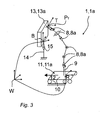
- the robot base 9 are automatically approximated to the predetermined reference point P, in particular to the operating point P A or to the tool reference point P T , so that this easier, that is achievable by the end effector 3a and the tool reference point P T , ie with more favorable axis positions of the manipulator arm 1a or like this in Fig. 3 is shown schematically.
- a modified embodiment of the invention may, as in Fig. 4 schematically indicated, an automatic change of the position values of the robot base 9 carried out such that as a predetermined reference point P is not the operating point P A , but the tool reference point P T is used.
- the robot base 9 does not approach the working point P A but the tool reference point P T.
- the robot base 9 is driven by the carriage 10 of the additional axis 11 more or less always below the tool reference point P T or under the end effector 3a.
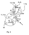
- a one-dimensional additional axis 11 may be, but, as in Fig. 5 indicated by the arrow, can also form a two-dimensional additional axis 11.
- the two-dimensional additional axle 11 may be a travel platform, in particular an omnidirectional chassis.
- an automatic change of the position values of the robot base 9 can also take place such that a point lying both near the working point P A and near the tool reference point P T is used as the predetermined reference point P. In this embodiment, however, only the operating point P A or the tool reference point P T can be used as a predetermined reference point P.
Landscapes
- Engineering & Computer Science (AREA)
- Robotics (AREA)
- Mechanical Engineering (AREA)
- Health & Medical Sciences (AREA)
- General Health & Medical Sciences (AREA)
- Orthopedic Medicine & Surgery (AREA)
- Manipulator (AREA)
- Numerical Control (AREA)
- Human Computer Interaction (AREA)
- Manufacturing & Machinery (AREA)
- Physics & Mathematics (AREA)
- General Physics & Mathematics (AREA)
- Automation & Control Theory (AREA)
Applications Claiming Priority (1)
| Application Number | Priority Date | Filing Date | Title |
|---|---|---|---|
| DE102011084412A DE102011084412A1 (de) | 2011-10-13 | 2011-10-13 | Robotersteuerungsverfahren |
Publications (3)
| Publication Number | Publication Date |
|---|---|
| EP2581177A2 true EP2581177A2 (fr) | 2013-04-17 |
| EP2581177A3 EP2581177A3 (fr) | 2017-11-29 |
| EP2581177B1 EP2581177B1 (fr) | 2022-02-16 |
Family
ID=47215373
Family Applications (1)
| Application Number | Title | Priority Date | Filing Date |
|---|---|---|---|
| EP12186961.4A Active EP2581177B1 (fr) | 2011-10-13 | 2012-10-02 | Procédé de commande de robot |
Country Status (5)
| Country | Link |
|---|---|
| US (1) | US9266238B2 (fr) |
| EP (1) | EP2581177B1 (fr) |
| KR (1) | KR102013459B1 (fr) |
| CN (1) | CN103042527B (fr) |
| DE (1) | DE102011084412A1 (fr) |
Families Citing this family (33)
| Publication number | Priority date | Publication date | Assignee | Title |
|---|---|---|---|---|
| US10725478B2 (en) * | 2013-07-02 | 2020-07-28 | The Boeing Company | Robotic-mounted monument system for metrology systems |
| US9555545B2 (en) * | 2014-05-21 | 2017-01-31 | Bot & Dolly, Llc | Systems and methods for time-based parallel robotic operation |
| JP6416560B2 (ja) * | 2014-09-11 | 2018-10-31 | 株式会社デンソー | 位置決め制御装置 |
| KR102361641B1 (ko) | 2014-12-26 | 2022-02-10 | 삼성전자주식회사 | 위치 정보 처리 방법 및 그것을 포함하는 계측 정보 처리 방법 |
| DE102015204599B3 (de) * | 2015-03-13 | 2016-08-11 | Kuka Roboter Gmbh | Verfahren zur Steuerung eines Manipulators zur Ausführung eines Arbeitsprozesses |
| JP6562665B2 (ja) * | 2015-03-18 | 2019-08-21 | 蛇の目ミシン工業株式会社 | ロボット |
| DE102015211865B3 (de) | 2015-06-25 | 2016-05-12 | Kuka Roboter Gmbh | Verfahren zum redundanzoptimierten Planen eines Betriebs eines mobilen Roboters |
| JP6407826B2 (ja) | 2015-09-03 | 2018-10-17 | ファナック株式会社 | 座標系設定方法、座標系設定装置、及び座標系設定装置を備えたロボットシステム |
| CN105313122A (zh) * | 2015-11-19 | 2016-02-10 | 上海交通大学 | 机器人打磨装置 |
| WO2017097377A1 (fr) * | 2015-12-11 | 2017-06-15 | Abb Schweiz Ag | Robot industriel, et procédé permettant de commander le robot afin de sélectionner automatiquement le code de programme à exécuter ensuite |
| DE102016005029A1 (de) * | 2016-04-26 | 2017-10-26 | Kuka Roboter Gmbh | Roboter mit mobilem Träger und Manipulator |
| JP7061119B2 (ja) | 2016-07-15 | 2022-04-27 | ファストブリック・アイピー・プロプライエタリー・リミテッド | 車両に組み込まれた煉瓦/ブロック敷設機 |
| ES2899585T3 (es) | 2016-07-15 | 2022-03-14 | Fastbrick Ip Pty Ltd | Pluma para transporte de material |
| DE102016013891A1 (de) * | 2016-11-21 | 2018-05-24 | Kuka Roboter Gmbh | Vermessen einer Bewegungsachse eines Roboters |
| CN111095355B (zh) | 2017-07-05 | 2023-10-20 | 快砖知识产权私人有限公司 | 实时定位和定向跟踪器 |
| EP3443908B1 (fr) * | 2017-08-15 | 2021-01-06 | Siemens Healthcare GmbH | Procédé de fonctionnement d'un appareil à rayons x pourvu d'un bras articulé et appareil à rayon x pourvu d'un bras articulé |
| US11958193B2 (en) * | 2017-08-17 | 2024-04-16 | Fastbrick Ip Pty Ltd | Communication system for an interaction system |
| AU2018317941B2 (en) | 2017-08-17 | 2023-11-09 | Fastbrick Ip Pty Ltd | Laser tracker with improved roll angle measurement |
| CN107443380B (zh) * | 2017-09-05 | 2019-11-29 | 北京京东尚科信息技术有限公司 | 直角坐标机器人的控制方法和控制装置 |
| JP6592053B2 (ja) * | 2017-10-11 | 2019-10-16 | ファナック株式会社 | 作業ツールの移動方向を監視する制御装置 |
| CN111212799B (zh) | 2017-10-11 | 2023-04-14 | 快砖知识产权私人有限公司 | 用于传送物体的机器以及与其一起使用的多隔间转盘 |
| DE102017009939B4 (de) * | 2017-10-25 | 2021-07-01 | Kuka Deutschland Gmbh | Verfahren und System zum Betreiben eines mobilen Roboters |
| CN108044623B (zh) * | 2017-12-07 | 2021-01-01 | 河南广播电视大学 | 基于单片机实训的机械臂联动控制方法和系统 |
| US11325263B2 (en) * | 2018-06-29 | 2022-05-10 | Teradyne, Inc. | System and method for real-time robotic control |
| US12311546B2 (en) | 2018-07-16 | 2025-05-27 | Fastbrick Ip Pty Ltd | Active damping system |
| WO2020014737A1 (fr) | 2018-07-16 | 2020-01-23 | Fastbrick Ip Pty Ltd | Suivi de sauvegarde pour système d'interactions |
| US12144574B2 (en) * | 2018-10-31 | 2024-11-19 | Intuitive Surgical Operations, Inc. | System and method for assisting tool exchange |
| CN112091960B (zh) * | 2019-06-17 | 2024-08-02 | 库卡机器人(广东)有限公司 | 机器人、用于机器人的接触检测方法和相关装置 |
| CN115443363A (zh) | 2020-04-22 | 2022-12-06 | 快砖知识产权私人有限公司 | 块传送装置及用于与其一起使用的改进的夹紧组件 |
| AU2021304545B2 (en) | 2020-07-08 | 2025-12-04 | Fastbrick Ip Pty Ltd | Adhesive application system |
| GB2594536B (en) * | 2020-10-12 | 2022-05-18 | Insphere Ltd | Photogrammetry system |
| DE102021212542B3 (de) | 2021-11-08 | 2022-12-22 | Volkswagen Aktiengesellschaft | Verfahren zum Betreiben eines mehrachsigen Roboters und Roboter |
| CN116890328B (zh) * | 2023-08-24 | 2026-02-17 | 库卡机器人制造(上海)有限公司 | 轴值确定方法、装置、存储介质、程序产品和机器人 |
Citations (1)
| Publication number | Priority date | Publication date | Assignee | Title |
|---|---|---|---|---|
| EP0271691A1 (fr) | 1986-11-17 | 1988-06-22 | Siemens Aktiengesellschaft | Méthode pour commander le mouvement relatif en trois dimensions d'un robot par rapport à une pièce fixée sur un support de pièce |
Family Cites Families (16)
| Publication number | Priority date | Publication date | Assignee | Title |
|---|---|---|---|---|
| JPS60193016A (ja) | 1984-03-14 | 1985-10-01 | Toyota Motor Corp | ロボツト装置 |
| JPS6142004A (ja) | 1984-08-06 | 1986-02-28 | Toyota Central Res & Dev Lab Inc | 追従ロボツト装置 |
| US4613803A (en) * | 1985-02-14 | 1986-09-23 | Kabushiki Kaisha Kobe Seiko Sho | Industrial robot and a method for positioning same |
| JPS61281305A (ja) | 1985-06-06 | 1986-12-11 | Toyota Motor Corp | 多関節ロボツト制御装置 |
| JP2786225B2 (ja) * | 1989-02-01 | 1998-08-13 | 株式会社日立製作所 | 工業用ロボットの制御方法及び装置 |
| JPH03196981A (ja) * | 1989-12-25 | 1991-08-28 | Fanuc Ltd | ロボットの付加軸追従制御方式 |
| EP0523889B1 (fr) | 1991-07-06 | 1996-12-27 | Daihen Corporation | Appareil pour contrÔler un robot industriel pour performer les opérations coordonnées utilisant un procédé d'enseignement à play-back et son procédé |
| US5550953A (en) * | 1994-04-20 | 1996-08-27 | The United States Of America As Represented By The Administrator Of The National Aeronautics And Space Administration | On-line method and apparatus for coordinated mobility and manipulation of mobile robots |
| DE59308224D1 (de) | 1993-08-20 | 1998-04-09 | Siemens Ag | Verfahren zur numerischen Steuerung von mehrachsigen kinematischen Systemen |
| US6325749B1 (en) * | 1996-10-18 | 2001-12-04 | Kabushiki Kaisha Yaskawa Denki | Robot vehicle for hot-line job |
| US6435397B2 (en) * | 2000-04-18 | 2002-08-20 | Progressive Tool & Industries Co. | Robotic turntable |
| US6873880B2 (en) * | 2001-12-26 | 2005-03-29 | Lockheed Martin Corporation | Machine for performing machining operations on a workpiece and method of controlling same |
| US8255092B2 (en) * | 2007-05-14 | 2012-08-28 | Irobot Corporation | Autonomous behaviors for a remote vehicle |
| JP2009028871A (ja) | 2007-07-30 | 2009-02-12 | Denso Wave Inc | ロボット制御装置 |
| DE102009014766B4 (de) | 2009-03-25 | 2012-02-09 | Fraunhofer-Gesellschaft zur Förderung der angewandten Forschung e.V. | Überlagerte Achsen bei einer Vorrichtung zur Bearbeitung eines Werkstücks mit einem Werkzeug |
| SE1050763A1 (sv) * | 2010-07-08 | 2010-07-12 | Abb Research Ltd | En metod för att kalibrera en mobil robot |
-
2011
- 2011-10-13 DE DE102011084412A patent/DE102011084412A1/de not_active Ceased
-
2012
- 2012-10-02 EP EP12186961.4A patent/EP2581177B1/fr active Active
- 2012-10-12 KR KR1020120113676A patent/KR102013459B1/ko active Active
- 2012-10-12 US US13/650,384 patent/US9266238B2/en active Active
- 2012-10-15 CN CN201210390783.XA patent/CN103042527B/zh active Active
Patent Citations (1)
| Publication number | Priority date | Publication date | Assignee | Title |
|---|---|---|---|---|
| EP0271691A1 (fr) | 1986-11-17 | 1988-06-22 | Siemens Aktiengesellschaft | Méthode pour commander le mouvement relatif en trois dimensions d'un robot par rapport à une pièce fixée sur un support de pièce |
Also Published As
| Publication number | Publication date |
|---|---|
| US20130103192A1 (en) | 2013-04-25 |
| DE102011084412A1 (de) | 2013-04-18 |
| US9266238B2 (en) | 2016-02-23 |
| CN103042527A (zh) | 2013-04-17 |
| EP2581177A3 (fr) | 2017-11-29 |
| EP2581177B1 (fr) | 2022-02-16 |
| CN103042527B (zh) | 2016-01-20 |
| KR102013459B1 (ko) | 2019-08-22 |
| KR20130040153A (ko) | 2013-04-23 |
Similar Documents
| Publication | Publication Date | Title |
|---|---|---|
| EP2581177A2 (fr) | Procédé de commande de robot | |
| EP1424613B1 (fr) | Procédé et dispositif d'usinage d'une pièce | |
| EP1950010B1 (fr) | Robot et procédé de programmation d'un robot | |
| DE102009049172B4 (de) | Verfahren und Vorrichtung zur Steuerung eines Manipulators | |
| EP2851162B1 (fr) | Procédé de réglage manuel de la pose d'un bras manipulateur d'un robot industriel et robot industriel associé | |
| EP2987592B1 (fr) | Procede de programmation d'un robot industriel et robot industriel correspondant | |
| DE102013109876B4 (de) | Verfahren zur Steuerung eines redundanten Roboters | |
| EP2418555B1 (fr) | Procédé de programmation hors ligne d'un manipulateur à commande NC | |
| DE102015211865B3 (de) | Verfahren zum redundanzoptimierten Planen eines Betriebs eines mobilen Roboters | |
| DE102019126465B4 (de) | Verfahren und Vorrichtung zur Trajektorienbestimmung für serielle Manipulatoren | |
| DE102015114013B4 (de) | Verfahren und Vorrichtung zur Steuerung des Betriebs eines Roboters | |
| EP2303521A1 (fr) | Robot industriel et procédé de planification de trajectoire pour commander le déplacement d un robot industriel | |
| DE102006055359A1 (de) | Roboter und Verfahren zur Vermeidung einer Interferenz bei vielen Robotern | |
| WO2019197669A1 (fr) | Dispositif de pliage avec guidage de pièce à travers un robot à bras à articulations multiples | |
| DE102015202616A1 (de) | Verfahren zum Bearbeiten der Oberfläche eines dreidimensionalen Objekts | |
| EP3569367B1 (fr) | Détermination d'un mouvement d'un dispositif assistée par ordinateur | |
| DE102012008073A1 (de) | Verfahren und Mittel zum Vorgeben und/oder Steuern eines Manipulatorprozesses | |
| EP2676775B1 (fr) | Prédétermination de mouvements de robot synchronisés | |
| EP2359202A1 (fr) | Procédé et dispositif de sélection d'une position mémorisée d'un point de travail d'un manipulateur | |
| EP3218151B1 (fr) | Procédé de soudage pendulaire | |
| EP2504741B1 (fr) | Procédé d'élaboration d'un modèle de robot, et robot industriel | |
| EP3313627B1 (fr) | Transport d'une voie prédéterminée au moyen d'un robot | |
| EP3411196A1 (fr) | Robot à plusieurs axes ainsi que procédé de commande dudit robot pour peindre des objets | |
| DE102015109708B3 (de) | Verfahren zur Steuerung des Bewegungsablaufs einer motorisch angetriebenen Maschinen- oder Werkzeugkomponente | |
| WO2019086339A1 (fr) | Procédé et moyen de commande pour commander un système robotique |
Legal Events
| Date | Code | Title | Description |
|---|---|---|---|
| PUAI | Public reference made under article 153(3) epc to a published international application that has entered the european phase |
Free format text: ORIGINAL CODE: 0009012 |
|
| AK | Designated contracting states |
Kind code of ref document: A2 Designated state(s): AL AT BE BG CH CY CZ DE DK EE ES FI FR GB GR HR HU IE IS IT LI LT LU LV MC MK MT NL NO PL PT RO RS SE SI SK SM TR |
|
| AX | Request for extension of the european patent |
Extension state: BA ME |
|
| PUAL | Search report despatched |
Free format text: ORIGINAL CODE: 0009013 |
|
| AK | Designated contracting states |
Kind code of ref document: A3 Designated state(s): AL AT BE BG CH CY CZ DE DK EE ES FI FR GB GR HR HU IE IS IT LI LT LU LV MC MK MT NL NO PL PT RO RS SE SI SK SM TR |
|
| AX | Request for extension of the european patent |
Extension state: BA ME |
|
| RIC1 | Information provided on ipc code assigned before grant |
Ipc: B25J 9/16 20060101AFI20171020BHEP Ipc: G05B 19/402 20060101ALI20171020BHEP |
|
| STAA | Information on the status of an ep patent application or granted ep patent |
Free format text: STATUS: REQUEST FOR EXAMINATION WAS MADE |
|
| 17P | Request for examination filed |
Effective date: 20180522 |
|
| RBV | Designated contracting states (corrected) |
Designated state(s): AL AT BE BG CH CY CZ DE DK EE ES FI FR GB GR HR HU IE IS IT LI LT LU LV MC MK MT NL NO PL PT RO RS SE SI SK SM TR |
|
| RAP1 | Party data changed (applicant data changed or rights of an application transferred) |
Owner name: KUKA DEUTSCHLAND GMBH |
|
| STAA | Information on the status of an ep patent application or granted ep patent |
Free format text: STATUS: EXAMINATION IS IN PROGRESS |
|
| 17Q | First examination report despatched |
Effective date: 20200811 |
|
| GRAP | Despatch of communication of intention to grant a patent |
Free format text: ORIGINAL CODE: EPIDOSNIGR1 |
|
| STAA | Information on the status of an ep patent application or granted ep patent |
Free format text: STATUS: GRANT OF PATENT IS INTENDED |
|
| INTG | Intention to grant announced |
Effective date: 20210915 |
|
| GRAS | Grant fee paid |
Free format text: ORIGINAL CODE: EPIDOSNIGR3 |
|
| GRAA | (expected) grant |
Free format text: ORIGINAL CODE: 0009210 |
|
| STAA | Information on the status of an ep patent application or granted ep patent |
Free format text: STATUS: THE PATENT HAS BEEN GRANTED |
|
| AK | Designated contracting states |
Kind code of ref document: B1 Designated state(s): AL AT BE BG CH CY CZ DE DK EE ES FI FR GB GR HR HU IE IS IT LI LT LU LV MC MK MT NL NO PL PT RO RS SE SI SK SM TR |
|
| REG | Reference to a national code |
Ref country code: GB Ref legal event code: FG4D Free format text: NOT ENGLISH |
|
| REG | Reference to a national code |
Ref country code: CH Ref legal event code: EP |
|
| REG | Reference to a national code |
Ref country code: DE Ref legal event code: R096 Ref document number: 502012016988 Country of ref document: DE |
|
| REG | Reference to a national code |
Ref country code: AT Ref legal event code: REF Ref document number: 1468607 Country of ref document: AT Kind code of ref document: T Effective date: 20220315 |
|
| REG | Reference to a national code |
Ref country code: IE Ref legal event code: FG4D Free format text: LANGUAGE OF EP DOCUMENT: GERMAN |
|
| REG | Reference to a national code |
Ref country code: LT Ref legal event code: MG9D |
|
| REG | Reference to a national code |
Ref country code: NL Ref legal event code: MP Effective date: 20220216 |
|
| PG25 | Lapsed in a contracting state [announced via postgrant information from national office to epo] |
Ref country code: SE Free format text: LAPSE BECAUSE OF FAILURE TO SUBMIT A TRANSLATION OF THE DESCRIPTION OR TO PAY THE FEE WITHIN THE PRESCRIBED TIME-LIMIT Effective date: 20220216 Ref country code: RS Free format text: LAPSE BECAUSE OF FAILURE TO SUBMIT A TRANSLATION OF THE DESCRIPTION OR TO PAY THE FEE WITHIN THE PRESCRIBED TIME-LIMIT Effective date: 20220216 Ref country code: PT Free format text: LAPSE BECAUSE OF FAILURE TO SUBMIT A TRANSLATION OF THE DESCRIPTION OR TO PAY THE FEE WITHIN THE PRESCRIBED TIME-LIMIT Effective date: 20220616 Ref country code: NO Free format text: LAPSE BECAUSE OF FAILURE TO SUBMIT A TRANSLATION OF THE DESCRIPTION OR TO PAY THE FEE WITHIN THE PRESCRIBED TIME-LIMIT Effective date: 20220516 Ref country code: NL Free format text: LAPSE BECAUSE OF FAILURE TO SUBMIT A TRANSLATION OF THE DESCRIPTION OR TO PAY THE FEE WITHIN THE PRESCRIBED TIME-LIMIT Effective date: 20220216 Ref country code: LT Free format text: LAPSE BECAUSE OF FAILURE TO SUBMIT A TRANSLATION OF THE DESCRIPTION OR TO PAY THE FEE WITHIN THE PRESCRIBED TIME-LIMIT Effective date: 20220216 Ref country code: HR Free format text: LAPSE BECAUSE OF FAILURE TO SUBMIT A TRANSLATION OF THE DESCRIPTION OR TO PAY THE FEE WITHIN THE PRESCRIBED TIME-LIMIT Effective date: 20220216 Ref country code: ES Free format text: LAPSE BECAUSE OF FAILURE TO SUBMIT A TRANSLATION OF THE DESCRIPTION OR TO PAY THE FEE WITHIN THE PRESCRIBED TIME-LIMIT Effective date: 20220216 Ref country code: BG Free format text: LAPSE BECAUSE OF FAILURE TO SUBMIT A TRANSLATION OF THE DESCRIPTION OR TO PAY THE FEE WITHIN THE PRESCRIBED TIME-LIMIT Effective date: 20220516 |
|
| PG25 | Lapsed in a contracting state [announced via postgrant information from national office to epo] |
Ref country code: PL Free format text: LAPSE BECAUSE OF FAILURE TO SUBMIT A TRANSLATION OF THE DESCRIPTION OR TO PAY THE FEE WITHIN THE PRESCRIBED TIME-LIMIT Effective date: 20220216 Ref country code: LV Free format text: LAPSE BECAUSE OF FAILURE TO SUBMIT A TRANSLATION OF THE DESCRIPTION OR TO PAY THE FEE WITHIN THE PRESCRIBED TIME-LIMIT Effective date: 20220216 Ref country code: GR Free format text: LAPSE BECAUSE OF FAILURE TO SUBMIT A TRANSLATION OF THE DESCRIPTION OR TO PAY THE FEE WITHIN THE PRESCRIBED TIME-LIMIT Effective date: 20220517 Ref country code: FI Free format text: LAPSE BECAUSE OF FAILURE TO SUBMIT A TRANSLATION OF THE DESCRIPTION OR TO PAY THE FEE WITHIN THE PRESCRIBED TIME-LIMIT Effective date: 20220216 |
|
| PG25 | Lapsed in a contracting state [announced via postgrant information from national office to epo] |
Ref country code: IS Free format text: LAPSE BECAUSE OF FAILURE TO SUBMIT A TRANSLATION OF THE DESCRIPTION OR TO PAY THE FEE WITHIN THE PRESCRIBED TIME-LIMIT Effective date: 20220616 |
|
| PG25 | Lapsed in a contracting state [announced via postgrant information from national office to epo] |
Ref country code: SM Free format text: LAPSE BECAUSE OF FAILURE TO SUBMIT A TRANSLATION OF THE DESCRIPTION OR TO PAY THE FEE WITHIN THE PRESCRIBED TIME-LIMIT Effective date: 20220216 Ref country code: SK Free format text: LAPSE BECAUSE OF FAILURE TO SUBMIT A TRANSLATION OF THE DESCRIPTION OR TO PAY THE FEE WITHIN THE PRESCRIBED TIME-LIMIT Effective date: 20220216 Ref country code: RO Free format text: LAPSE BECAUSE OF FAILURE TO SUBMIT A TRANSLATION OF THE DESCRIPTION OR TO PAY THE FEE WITHIN THE PRESCRIBED TIME-LIMIT Effective date: 20220216 Ref country code: EE Free format text: LAPSE BECAUSE OF FAILURE TO SUBMIT A TRANSLATION OF THE DESCRIPTION OR TO PAY THE FEE WITHIN THE PRESCRIBED TIME-LIMIT Effective date: 20220216 Ref country code: DK Free format text: LAPSE BECAUSE OF FAILURE TO SUBMIT A TRANSLATION OF THE DESCRIPTION OR TO PAY THE FEE WITHIN THE PRESCRIBED TIME-LIMIT Effective date: 20220216 Ref country code: CZ Free format text: LAPSE BECAUSE OF FAILURE TO SUBMIT A TRANSLATION OF THE DESCRIPTION OR TO PAY THE FEE WITHIN THE PRESCRIBED TIME-LIMIT Effective date: 20220216 |
|
| REG | Reference to a national code |
Ref country code: DE Ref legal event code: R097 Ref document number: 502012016988 Country of ref document: DE |
|
| PG25 | Lapsed in a contracting state [announced via postgrant information from national office to epo] |
Ref country code: AL Free format text: LAPSE BECAUSE OF FAILURE TO SUBMIT A TRANSLATION OF THE DESCRIPTION OR TO PAY THE FEE WITHIN THE PRESCRIBED TIME-LIMIT Effective date: 20220216 |
|
| PLBE | No opposition filed within time limit |
Free format text: ORIGINAL CODE: 0009261 |
|
| STAA | Information on the status of an ep patent application or granted ep patent |
Free format text: STATUS: NO OPPOSITION FILED WITHIN TIME LIMIT |
|
| 26N | No opposition filed |
Effective date: 20221117 |
|
| PG25 | Lapsed in a contracting state [announced via postgrant information from national office to epo] |
Ref country code: SI Free format text: LAPSE BECAUSE OF FAILURE TO SUBMIT A TRANSLATION OF THE DESCRIPTION OR TO PAY THE FEE WITHIN THE PRESCRIBED TIME-LIMIT Effective date: 20220216 |
|
| PG25 | Lapsed in a contracting state [announced via postgrant information from national office to epo] |
Ref country code: MC Free format text: LAPSE BECAUSE OF FAILURE TO SUBMIT A TRANSLATION OF THE DESCRIPTION OR TO PAY THE FEE WITHIN THE PRESCRIBED TIME-LIMIT Effective date: 20220216 |
|
| REG | Reference to a national code |
Ref country code: BE Ref legal event code: MM Effective date: 20221031 |
|
| PG25 | Lapsed in a contracting state [announced via postgrant information from national office to epo] |
Ref country code: LU Free format text: LAPSE BECAUSE OF NON-PAYMENT OF DUE FEES Effective date: 20221002 |
|
| P01 | Opt-out of the competence of the unified patent court (upc) registered |
Effective date: 20230528 |
|
| PG25 | Lapsed in a contracting state [announced via postgrant information from national office to epo] |
Ref country code: IT Free format text: LAPSE BECAUSE OF FAILURE TO SUBMIT A TRANSLATION OF THE DESCRIPTION OR TO PAY THE FEE WITHIN THE PRESCRIBED TIME-LIMIT Effective date: 20220216 |
|
| PG25 | Lapsed in a contracting state [announced via postgrant information from national office to epo] |
Ref country code: BE Free format text: LAPSE BECAUSE OF NON-PAYMENT OF DUE FEES Effective date: 20221031 |
|
| PG25 | Lapsed in a contracting state [announced via postgrant information from national office to epo] |
Ref country code: IE Free format text: LAPSE BECAUSE OF NON-PAYMENT OF DUE FEES Effective date: 20221002 |
|
| REG | Reference to a national code |
Ref country code: AT Ref legal event code: MM01 Ref document number: 1468607 Country of ref document: AT Kind code of ref document: T Effective date: 20221002 |
|
| PG25 | Lapsed in a contracting state [announced via postgrant information from national office to epo] |
Ref country code: AT Free format text: LAPSE BECAUSE OF NON-PAYMENT OF DUE FEES Effective date: 20221002 |
|
| PG25 | Lapsed in a contracting state [announced via postgrant information from national office to epo] |
Ref country code: HU Free format text: LAPSE BECAUSE OF FAILURE TO SUBMIT A TRANSLATION OF THE DESCRIPTION OR TO PAY THE FEE WITHIN THE PRESCRIBED TIME-LIMIT; INVALID AB INITIO Effective date: 20121002 |
|
| PG25 | Lapsed in a contracting state [announced via postgrant information from national office to epo] |
Ref country code: CY Free format text: LAPSE BECAUSE OF FAILURE TO SUBMIT A TRANSLATION OF THE DESCRIPTION OR TO PAY THE FEE WITHIN THE PRESCRIBED TIME-LIMIT Effective date: 20220216 |
|
| PG25 | Lapsed in a contracting state [announced via postgrant information from national office to epo] |
Ref country code: MK Free format text: LAPSE BECAUSE OF FAILURE TO SUBMIT A TRANSLATION OF THE DESCRIPTION OR TO PAY THE FEE WITHIN THE PRESCRIBED TIME-LIMIT Effective date: 20220216 |
|
| PG25 | Lapsed in a contracting state [announced via postgrant information from national office to epo] |
Ref country code: TR Free format text: LAPSE BECAUSE OF FAILURE TO SUBMIT A TRANSLATION OF THE DESCRIPTION OR TO PAY THE FEE WITHIN THE PRESCRIBED TIME-LIMIT Effective date: 20220216 |
|
| PG25 | Lapsed in a contracting state [announced via postgrant information from national office to epo] |
Ref country code: MT Free format text: LAPSE BECAUSE OF FAILURE TO SUBMIT A TRANSLATION OF THE DESCRIPTION OR TO PAY THE FEE WITHIN THE PRESCRIBED TIME-LIMIT Effective date: 20220216 |
|
| PGFP | Annual fee paid to national office [announced via postgrant information from national office to epo] |
Ref country code: GB Payment date: 20250904 Year of fee payment: 14 |
|
| PGFP | Annual fee paid to national office [announced via postgrant information from national office to epo] |
Ref country code: FR Payment date: 20250908 Year of fee payment: 14 |
|
| REG | Reference to a national code |
Ref country code: CH Ref legal event code: U11 Free format text: ST27 STATUS EVENT CODE: U-0-0-U10-U11 (AS PROVIDED BY THE NATIONAL OFFICE) Effective date: 20251101 |
|
| PGFP | Annual fee paid to national office [announced via postgrant information from national office to epo] |
Ref country code: DE Payment date: 20250902 Year of fee payment: 14 |
|
| PGFP | Annual fee paid to national office [announced via postgrant information from national office to epo] |
Ref country code: CH Payment date: 20251101 Year of fee payment: 14 |