EP2581614A2 - Module de basculement de sphère - Google Patents
Module de basculement de sphère Download PDFInfo
- Publication number
- EP2581614A2 EP2581614A2 EP20120185572 EP12185572A EP2581614A2 EP 2581614 A2 EP2581614 A2 EP 2581614A2 EP 20120185572 EP20120185572 EP 20120185572 EP 12185572 A EP12185572 A EP 12185572A EP 2581614 A2 EP2581614 A2 EP 2581614A2
- Authority
- EP
- European Patent Office
- Prior art keywords
- housing
- ball
- torsion spring
- pin
- module according
- Prior art date
- Legal status (The legal status is an assumption and is not a legal conclusion. Google has not performed a legal analysis and makes no representation as to the accuracy of the status listed.)
- Withdrawn
Links
- 230000003993 interaction Effects 0.000 claims description 4
- 238000011161 development Methods 0.000 description 4
- 230000018109 developmental process Effects 0.000 description 4
- 230000008878 coupling Effects 0.000 description 3
- 238000010168 coupling process Methods 0.000 description 3
- 238000005859 coupling reaction Methods 0.000 description 3
- 229910000639 Spring steel Inorganic materials 0.000 description 2
- 239000000969 carrier Substances 0.000 description 2
- 239000002184 metal Substances 0.000 description 2
- 241000309551 Arthraxon hispidus Species 0.000 description 1
- 230000015572 biosynthetic process Effects 0.000 description 1
- 238000007789 sealing Methods 0.000 description 1
Images


Classifications
-
- F—MECHANICAL ENGINEERING; LIGHTING; HEATING; WEAPONS; BLASTING
- F16—ENGINEERING ELEMENTS AND UNITS; GENERAL MEASURES FOR PRODUCING AND MAINTAINING EFFECTIVE FUNCTIONING OF MACHINES OR INSTALLATIONS; THERMAL INSULATION IN GENERAL
- F16C—SHAFTS; FLEXIBLE SHAFTS; ELEMENTS OR CRANKSHAFT MECHANISMS; ROTARY BODIES OTHER THAN GEARING ELEMENTS; BEARINGS
- F16C11/00—Pivots; Pivotal connections
- F16C11/04—Pivotal connections
- F16C11/10—Arrangements for locking
-
- B—PERFORMING OPERATIONS; TRANSPORTING
- B60—VEHICLES IN GENERAL
- B60D—VEHICLE CONNECTIONS
- B60D1/00—Traction couplings; Hitches; Draw-gear; Towing devices
- B60D1/48—Traction couplings; Hitches; Draw-gear; Towing devices characterised by the mounting
- B60D1/54—Traction couplings; Hitches; Draw-gear; Towing devices characterised by the mounting collapsible or retractable when not in use, e.g. hide-away hitches
Definitions
- the invention relates to a ball pivot module having a housing, a ball joint having a ball and extending in the direction of a journal pivot pin which is movably mounted by means of the ball joint in the housing, extending in an axial direction out of the housing and on the ball joint an uneven guide surface comprising a plurality of provided on the housing guide elements, which are in contact with the guide surface, and connected between the ball stud and the housing torsion spring whose voltage is variable by rotating the ball stud relative to the housing about the pin longitudinal axis.
- the DE 10 2008 002 207 A1 discloses a ball joint having a spigot-containing housing, a ball joint having a ball pin which is movably supported by means of the ball joint in the housing and extending through the pin opening through out of the housing, wherein the joint ball has an uneven ruled surface, with a to the unit provided in the housing is in contact.
- the ball joint has at least one transverse bore, in which at least one detent ball is movably guided, which can engage in a detent recess in the housing.
- a perpendicular to the transverse bore aligned longitudinal bore is provided in which a locking pin is resiliently mounted, which can press the detent ball in the recess.
- the DE 10 2009 046 631 A1 discloses a ball pivot module comprising a housing, a ball stud comprising a ball joint, which is movably mounted with its ball joint in the housing and extends out of this, a guide element mounted in the housing against which the ball stud bears with a guide surface provided on the ball joint, so that the ball pin is movable relative to the housing between two end positions along a predetermined path of movement, wherein a torsion spring arranged in the housing and connected between the ball stud and the housing is provided, against the spring force of which the ball stud can move into at least one of the end positions relative to the housing is.
- the guide element comprises two mutually opposite bearing sleeves and a guide element pin on which the bearing sleeves are mounted.
- Guide element bolt extends transversely through an interior of the housing, is mounted on both sides of the housing and forms the housing-side deposit of the torsion spring. Further, a locking device is provided, by means of which the ball pin can be locked to the housing in the end positions.
- the torsion spring between the ball stud and the guide element bolt is tensioned and also deformed.
- the locking device according to the DE 10 2009 046 631 A1 a locking pin according to DE 10 2008 002 207 A1 used, so the axial adjustment of the locking bolt can be hindered due to the deformation of the spring.
- the axial adjustment of the locking bolt can be limited by the fact that this abuts the guide element pin.
- the present invention seeks to be able to keep a deformation of the torsion spring in the ball stud low in a ball pivot module of the type mentioned.
- the ball pivot module in particular for a hitch for a vehicle, comprises a housing, a ball joint having a ball and extending in the direction of a pin longitudinal axis ball pivotally mounted by means of the ball joint in the housing, extending in an axial direction out of the housing and on the ball joint has an uneven guide surface, a plurality of provided on the housing guide elements which are in contact with the guide surface, and connected between the ball stud and the housing torsion spring whose voltage is variable by rotating the ball stud about the pin longitudinal axis relative to the housing, wherein the between the separately mounted on the housing guide elements extending torsion spring extends from the ball pin almost in the direction of the pin longitudinal axis of the guide elements over and is mounted at an axial distance to these on the housing.
- the guide elements are not mounted together on a guide element bolt, but separately from each other on the housing.
- the torsion spring it is possible to make the torsion spring longer because its length is not limited by such a guide element pin. If the torsion spring is longer, but also a deformation of the torsion spring due to a rotation of the ball pin relative to the housing distributed over a greater length, so that the deformation of the torsion spring can be kept low in the ball stud.
- the ball pivot module with a locking pin according to DE 10 2008 002 207 A1 equipped its axial adjustment is because of this small deformation less or no longer limited. Also, no guide element pin limits the ability to adjust the locking pin.
- the ball pivoting module in particular the housing, is preferably associated with a center longitudinal axis extending in the axial direction.
- the central longitudinal axis passes through the center of the joint ball.
- the journal longitudinal axis preferably extends through the center of the joint ball.
- the torsion spring preferably extends through the clearance in the axial direction and / or in the direction of the journal longitudinal axis.
- the number of guide elements is preferably equal to two.
- the guide elements are diametrically opposite each other with respect to the central longitudinal axis.
- the guide elements at a distance from each other, preferably in the radial direction.
- a radial connecting line between the guide elements preferably extends through the free space.
- the guide elements are opposite each other in the radial direction. In particular, any direction or any direction which is transverse to the axial direction is referred to as the radial direction.
- the torsion spring is mounted with a journal-side bearing on the ball stud and with a housing-side mounting on the housing.
- the bearings lie in the axial direction on different sides of the guide elements.
- the bearings each have an axial distance to the guide elements.
- the torsion spring in particular comprises a housing-side end region, by means of which the torsion spring is mounted on the housing.
- the torsion spring is mounted with the housing-side end portion on a bottom, in particular housing bottom of the housing, which preferably lies opposite the guide surface.
- the housing-side end region of the torsion spring advantageously extends transversely or obliquely to the journal longitudinal axis.
- the housing-side end portion of the torsion spring is in rotary driving connection with the housing, in particular with the housing bottom. This rotational drive connection can be realized with and without play.
- the housing-side end portion of the torsion spring but with play in rotationally driving connection with the housing, in particular with the housing bottom, which will be explained.
- the torsion spring in particular comprises a journal-side end region, by means of which the torsion spring is mounted on the ball pivot.
- the journal-side end region of the torsion spring advantageously extends in the direction of the journal longitudinal axis.
- the journal-side end portion of the torsion spring is in rotary driving connection with the ball stud. This rotational drive connection can be realized with and without play.
- the pin-side end portion of the torsion spring is play-free in rotary driving connection with the ball pin.
- the torsion spring in particular the housing-side end region of the torsion spring, mounted by means of one or more drivers on the housing.
- the one or more drivers are arranged in the housing.
- the housing-side end region of the torsion spring and the driver or carriers engage in one another in a form-fitting manner.
- the one or more drivers are preferably fixed, in particular rigid, connected to the housing and / or integrally formed therewith.
- the driver or carriers are arranged in the axial direction on a side facing away from the ball pin side of the guide elements and have to these preferably at a distance.
- the one or more drivers are provided on the housing bottom.
- the one or more drivers extend for example in the axial direction.
- the drivers arranged at a distance from each other, so that the housing-side end portion is preferably arranged between the drivers.
- the drivers comprise or form projections provided on the bottom of the housing, which extend in the axial direction and are spaced apart from one another, between which the housing-side end region of the torsion spring is arranged.
- the projections are fixed, in particular rigid, connected to the housing bottom and / or formed integrally therewith.
- the projections are formed for example in the form of bolts, pins or sleeves.
- the number of protrusions is four.
- the projections are combined into pairs, between which the housing-side end portion is arranged.
- a groove is provided on the housing bottom, in which rests the housing-side end portion of the torsion spring.
- the groove preferably extends transversely to the axial direction.
- the drivers comprise or form elevations, which are provided at the bottom of the housing and extend in the axial direction and are spaced from one another, which define the groove.
- the groove runs between the surveys.
- the projections are preferably fixed, in particular rigid, connected to the housing bottom and / or formed integrally therewith.
- the torsion spring is preferably applied to a spring bearing surface provided on the ball stud.
- the spring bearing surface is surrounded by the guide surface.
- a Drehfederageausappelung is provided in the ball joint, in which engages the torsion spring and / or dips.
- the spring bearing surface is preferably provided in this case at the bottom of the Drehfederageausappelung.
- the opening of the Drehfederfactausappelung is surrounded by the guide surface.
- engage the pin-side end portion of the torsion spring and the ball pin form-fitting manner.
- the journal-side end region of the torsion spring engages in a hole made in the ball stud, which preferably extends in the direction of the journal longitudinal axis.
- this hole is arranged offset transversely to the pin longitudinal axis and thus has a distance to this.
- this hole is provided in the spring bearing surface.
- the torsion spring is designed as a helical spring. Since the torsion spring is longer than can be formed in the prior art, it can have a larger number of turns, which is in particular associated with an improved dynamic durability of the torsion spring.
- the torsion spring comprises a helically wound region with which the torsion spring extends in the direction of the longitudinal axis of the pin, in particular on the guide elements.
- the torsion spring extends with its helically wound region through the free space.
- the housing-side end portion of the torsion spring is preferably bent from the helical portion, in particular transversely or obliquely to the pin longitudinal axis.
- the housing-side end portion of the torsion spring may also be bent axially or in the direction of the pin longitudinal axis of the helical portion and engage in a hole introduced in the housing bottom, which preferably extends in the axial direction.
- the journal-side end region of the torsion spring is preferably bent away from the helical region in the direction of the journal longitudinal axis.
- the torsion spring is preferably made of metal, in particular spring steel.
- the torsion spring preferably consists of wire, for example of metal wire, in particular of spring steel wire. If the torsion spring is designed as a helical spring, the helically wound region of the torsion spring thus preferably consists of this wire, which in particular is helically wound.
- the ball pivot module comprises a locking device, by means of which the ball pin can be locked to the housing.
- the ball pin is lockable by means of the locking device in two or at least two positions, one of which e.g. as operating position and the other or another e.g. is designated as rest position.
- the locking device preferably comprises a locking pin which is displaceably guided in the direction of the pin longitudinal axis in the ball pin and by means of which the locking device can preferably be actuated.
- the locking pin in a provided in the ball stud and extending in the direction of the pin longitudinal axis locking pin hole.
- the locking pin hole extends in the direction of the pin longitudinal axis through the ball pin.
- the locking pin hole opens into the DrehfederageausEnglishung, if it is present.
- the ball pin is lockable to the housing by engaging the locking element in the Arret istsausEnglishung.
- the locking element may be formed one or more parts.
- the wall preferably runs around the joint ball.
- the wall defines an interior of the housing in which the ball joint is arranged.
- the wall is rigidly connected to the bottom of the housing and / or formed integrally therewith.
- the bottom can be designed as a fixed, in particular rigid or torsionally rigid, lid connected to the wall.
- the interior is also limited by the ground.
- the locking pin comprises an actuating surface extending obliquely to the pin longitudinal axis, by means of which the locking pin bears against the locking element.
- the locking pin is tensioned with a locking pin spring in the direction of the locking element.
- the shape of the guide surface differs in particular from the shape of the spherical surface of the joint ball.
- the guide surface forms a ruled surface.
- a ruled surface is understood in particular to mean a surface that can be generated by moving a straight line in space. It is advantageous by the interaction the guide elements with the guide surface rotation of the ball pin relative to the housing about the pin longitudinal axis depending on a lateral deflection of the ball pin relative to the housing. Such a lateral deflection of the ball pin takes place, for example, about at least one pivot axis which extends obliquely or perpendicular to the pin longitudinal axis.
- the at least one pivot axis extends through the center of the joint ball.
- the guide surface forms in particular an end face, preferably a free end face of the ball stud.
- the guide surface surrounds the journal longitudinal axis.
- the guide elements are in each case with the guide surface in point contact or in line contact.
- the points of contact and / or lines of contact of the guide elements with the guide surface are all located on a common straight line. If these requirements are met, the guide elements can basically have any shape.
- the guide elements each have a tapering in the direction of the guide surface of the ball joint head contour with which rest the guide elements on the guide surface or are in point or line contact. Head contour here means the contour in the direction of the guide surface.
- the guide elements are e.g. designed as balls, as pins, as sleeves or as sliding blocks.
- the pins and / or the sleeves are in particular cylindrical or barrel-shaped.
- the guide elements each form a body of revolution.
- the cylinders are formed at one end or at their ends lens or dome-shaped or have a convex end face.
- deposits are provided in the housing in which the guide elements are mounted and / or einine.
- the deposits may, for example, each be formed as a recess in the housing, which is, for example, cylindrical, trough-shaped, cup-shaped, trough-shaped or channel-shaped.
- the depressions are in particular axial depressions in the manner of a bore or a blind hole.
- the ball pin comprises a pin portion rigidly connected to the ball joint, which extends in particular in the direction of the pin longitudinal axis.
- the guide surface is provided on a side facing away from the pin portion of the ball joint.
- the ball pin extends with its pin portion out of the housing.
- the ball pin is preferably mounted with the interposition of a bearing shell in the housing, which advantageously surrounds the ball joint.
- the housing preferably comprises a pin opening, through which the ball pin extends out of the housing.
- the pin portion is at least partially disposed outside of the housing.
- the ball pin extends with its pin portion through the pin opening.
- the pin opening is preferably formed as a slot and limits the lateral deflection of the ball pin in particular to the longitudinal direction of the slot.
- the possibility of movement of the ball pivot relative to the housing can thus be limited to a path of movement along which the ball pivot is positively guided.
- the bottom of the housing is preferably arranged opposite the pin opening. Further, the pin opening may be provided in a locking ring which is fixed, preferably rigid, connected to the housing.
- the locking ring is attributed in particular to the housing.
- the ball stud is preferably movable along one or the predetermined trajectory between two end positions relative to the housing.
- the end positions are attributed in particular to the movement path, so that the ball stud can assume the end positions.
- the ball pin can be locked in the end positions by means of the locking device with the housing.
- One of the end positions thus preferably forms the operating position, and the other end position preferably forms the rest position.
- the torsion spring is tension-free in a lying on the movement path position of the pin, which advantageously forms an intermediate position between the end positions of the pivotable pin.
- the stress-free position can be both in the middle of the movement path or offset to one of the end positions. But it is also possible that the tension-free position is formed by one of the end positions.
- the ball pin is convertible by rotation about the pin longitudinal axis relative to the housing against the force of the torsion spring in at least one of the end positions or in the end positions. In the tension-free position, a clearance can be provided for the ball pivot, so that it can be moved around the tension-free position relative to the housing a certain free travel, without tensioning the torsion spring.
- the middle of the trajectory is preferably within the free path.
- the free path can be symmetrical or asymmetrical with respect to the center of the movement path. But it is also possible that the middle of the trajectory is outside the free path.
- the play is preferably made possible by the bearing of the torsion spring on the housing, so that the housing-side end region is preferably mounted with play on the housing, in particular on the housing bottom.
- the housing-side end region can be stored with play on the carrier (s) and / or arranged with play between the drivers.
- the housing-side end region of the torsion spring can be mounted with play on the elevations and / or projections and / or projection pairs and / or arranged with play between the elevations and / or projections and / or projection pairs.
- the housing-side end portion of the torsion spring is a game in the groove.
- the groove is flared towards its ends, in particular towards its radial ends.
- widening is meant, for example, a circular segment-like franking.
- the end portion of the torsion spring can thus pivot within the groove or its pivotal movement is limited by the groove.
- the journal-side end region is preferably mounted with clearance on the ball pivot.
- the ball stud and the housing each form a hinge part, one of the hinge parts fixed, in particular rigid, is connected to a ball bar, which carries a coupling ball at its free end.
- the other of the joint parts is preferably fixed, in particular rigid, connected or connectable to a vehicle component and / or a vehicle body of the vehicle or of a vehicle.
- the other joint part is firmly connected or connectable to a vehicle cross member of the vehicle.
- the ball pivot module is thus advantageously part of a hitch or trailer hitch of the vehicle.
- Fig. 1 is a longitudinal section through a partially illustrated ball pivot module 1 according to a first embodiment can be seen, wherein a joint ball 2 comprehensive ball stud 3 is movably mounted in a housing 5 with the interposition of the ball joint 2 enclosing bearing shell 4.
- the ball pin 3 comprises a pin portion 11 rigidly connected to the ball joint 2 and extends in the direction of a pin longitudinal axis 6 which extends through the center of the ball joint 2.
- the bearing shell 4 and the joint ball 2 are seated in an inner space 7 of the housing 5, which is here substantially cup-shaped.
- a locking ring 8 rigidly connected to the housing 5 closes the housing 5 and secures the bearing shell 4 and the joint ball 2 in an axial direction 9 in a form-fitting manner in the housing 5.
- the locking ring 8 is particularly attributed to the housing 5 and is provided with a pin opening formed as a slot 10, through which the ball pin 3 extends with its pin portion 11 in the axial direction 9 out of the housing 5 out.
- a sealing bellows 12 surrounding the pin opening 10 is defined, which extends from the locking ring 8 to the pin portion 11 and sealingly abuts this.
- the ball joint 2 On its side facing away from the pin portion 11, the ball joint 2 is provided with a guide surface 13, which forms an end face of the ball pin 3 and is formed as an uneven control surface. Due to the formation of the guide surface 13 as a control surface is the off Fig. 1 apparent section of the guide surface 13 on a straight line, although the guide surface 13 is uneven. However, by a rotation of the ball pin 3 relative to the housing 5 about the pin longitudinal axis 6, the inclination of this straight line would change.
- the guide surface 13 is located on guide elements 14 and 15, which are similarly formed and stored separately from each other in the housing 5. For this purpose, each of the guide elements on an axial projection 16 which sits in an opening provided in the housing 5 axial bore 17.
- each of the guide members 14 and 15 is seated in an axial recess 45 (see FIG Fig. 2 ), in which the respective axial bore 17 is inserted centrally. Since the guide elements 14 and 15 are secured by their projections 16 in the axial bores 17, the recesses 45 can also be omitted here.
- the guide elements 14 and 15 are respectively in line contact with the guide surface 13, wherein the lines of contact of the guide elements 14 and 15 lie with the guide surface 13 on a common straight line.
- the ball pin 3 is guided with its pin portion 11 in the pin opening 10, so that a deflection of the ball pin 3 only in the direction of the longitudinal direction of the pin hole 10 formed by the elongated hole is possible. However, a rotation of the ball pin 3 about the pin longitudinal axis 6 is permitted by the pin opening 10.
- a torsion spring 19 is connected, which extends from the ball stud 3 in the direction of the pin longitudinal axis 6 to a bottom 20 (housing bottom) of the housing 5, which is opposite to the guide surface 13.
- the torsion spring 19 is designed as a helical spring and has a bent in the direction of the pin longitudinal axis 6, pin-side end portion 21 which engages in a provided in the ball pin 3 bore 22 which extends in the direction of the pin longitudinal axis 6 and is arranged offset transversely to this (the The journal-side end portion 21 and the bore 22 are shown in the illustration Fig. 1 hidden and therefore indicated only by dashed lines).
- the pin-side end portion 21 is therefore in rotational engagement with the ball stud 3.
- a housing side End portion 23 of the torsion spring 19 is bent transversely to the pin longitudinal axis 6 and lies in a provided on the bottom 20 of the housing 5 and substantially radially extending groove 24 (see FIGS. 2 and 3 ) one.
- the housing-side end portion 23 is therefore in rotational drive connection with the housing 5, so that the tension of the torsion spring 19 can be changed by rotation of the ball stud 3 relative to the housing 5 about the journal longitudinal axis 6.
- the rotary driving connection of the housing-side end portion 23 to the housing 5 is, however, provided with a game, whereas the rotary driving connection of the pin-side end portion 23 is free of play or substantially free of play with the ball stud.
- the locking pin 26 is tensioned by a spring 31 in the direction of the journal longitudinal axis 6 against the locking element 28 and pushes it into a provided in the wall 29 locking recess 32 which is formed trough-shaped. In this state, the ball stud 3 is locked to the housing 5. If the locking pin 26 is moved in the direction of the arrow 9 against the force of the locking pin spring 31, the guide element 28 is disengaged from the locking recess 32 by means of a spring-loaded pressure pin 33, so that the ball pin 3 can move relative to the housing 5.
- a second Arretismesausnaturalung 34 is provided, which is formed trough-shaped and in which the locking element 28 can engage after rotation of the ball pin 3 about the pin longitudinal axis 6 by a predetermined angle, which is for example 180 °, so that the two Arret michsausEnglishept 32 and 34 are opposed to each other. If the locking element 28 engages in the locking recess 34, the ball pin 3 is locked to the housing 5.
- the locking recesses 32 and 34 thus define lockable end positions of the ball stud 3, which can be moved relative to the housing 5 between the end positions along a predetermined path of movement. A first of the end positions forms an operating position, which is assigned to the ArretmaschinesausEnglishung 32, and a second of the end positions forms a rest position, which is associated with the Arretmaschinesausnaturalung 34.
- the torsion spring 19 By turning the ball pin 3 about the pin longitudinal axis 6 relative to the housing, the torsion spring 19 is deformed. However, since a clearance 35 is provided between the guide elements 14 and 15, through which the torsion spring 19 extends from the ball stud 3 to the bottom 20 of the housing 5, the torsion spring 19 can be made relatively long, so that a deformation of the torsion spring 19th can be kept low in the sphere of the ball stud 3. An axial readjustment of the locking pin 26 is thus not hindered by a deformation of the torsion spring 19.
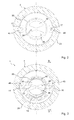
- Fig. 2 the housing bottom 20 is visible in plan view, on which two axial elevations 36 are provided, which limit the transverse to the journal longitudinal axis 6 extending groove 24, in which the housing-side end portion 23 of the torsion spring 19 rests. It can be seen that the groove 24 is not straight, but widens toward its radial ends. By the widened groove ends of the housing-side end portion 23 is limited rotatably relative to the housing 5, so that the ball pin 3 relative to the housing 5 with respect to a rotation about the journal longitudinal axis 6 has a game, which also Fig. 3 emerges that a section through the ball pivot module 1 along from Fig. 1 apparent section line AA shows.
- the load of the torsion spring 19 can be reduced, since it is not subjected to a change in voltage immediately in each position of the ball stud 3 by a movement thereof. Furthermore, it is off Fig. 3 a cut portion of the guide surface 13 can be seen, so that the uneven configuration of the guide surface 13 is clear.
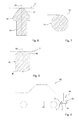
- Fig. 4 shows a section through the guide member 15 along the Fig. 3 apparent section line BB, wherein the guide member 15 has a tapered in the direction of the schematically indicated guide surface 13 head contour 37.
- the guide member 15 is in line contact with the guide surface 13.
- the guide elements in particular each form a sliding block.
- Fig. 5 shows a cross section through a ball pivot module 1 according to a second embodiment, wherein the first embodiment, similar or identical features with the same reference numerals as in the first embodiment are designated.
- a plurality of, here four, projections 38 are provided, which have a distance from one another and project in the axial direction 9 from the bottom 20 in the direction of the ball stud 3.
- the projections 38 are combined in pairs, wherein the housing-side end portion 23 of the torsion spring 19 rests in the space between two pairs of projections with clearance.
- the housing-side end portion 23 is therefore in rotation with the housing 5, which is provided with a game.
- the projections 38 in particular form a safety device which prevents axial disengagement of the housing-side end region 23 of the torsion spring 19 from the groove 24.
- the elevations 36 could also be dispensed with, so that the housing-side end region 23 is mounted on the housing 5 exclusively by means of the projections 38.
- the projections 38 are formed as cylindrical pins.
- the guide elements 14 and 15 are formed as balls, which eino in the recesses 45, which are formed in particular trough-shaped.
- the guide elements 14 and 15 are thus in point contact with the guide surface 13.
- Fig. 6 is a section through a guide member 15 according to a third embodiment can be seen, wherein the first embodiment, similar or identical features with the same reference numerals as in the first embodiment are designated.
- the guide member 15 can with its projection 16 in the associated bore 17 according to Fig. 1 are used, unlike the first embodiment However, with respect to a rotation axis 39 is rotationally symmetrical and is in point contact with the guide surface 13.
- the guide members according to the first embodiment may each be replaced by a guide member according to the third embodiment.
- Fig. 7 is a section through a guide member 15 according to a fourth embodiment can be seen, wherein the first embodiment, similar or identical features with the same reference numerals as in the first embodiment are designated.
- the guide element 15 is designed as a cylindrical pin and is therefore in line contact with the guide surface 13.
- the guide members according to the first embodiment may be replaced by a guide member according to the fourth embodiment, respectively.
- the depressions 45 are preferably channel-shaped.
- Fig. 8 is a section through a guide member 15 according to a fifth embodiment can be seen, wherein to the first embodiment, similar or identical features with the same reference numerals as in the first embodiment are designated.
- the guide element 15 is barrel-shaped and has convex end surfaces 46.
- the guide element 15 is rotationally symmetrical with respect to the axis of rotation 39 and is in one of its convex end surfaces 46 with the guide surface 13 in point contact.
- the guide surface 13 facing away from the end face of the guide element may alternatively but otherwise, for example, as a flat surface, be formed.
- the guide members according to the first embodiment may each be replaced by a guide member according to the fifth embodiment.
- Fig. 9 is a schematic side view of a motor vehicle 40 with a ball pivot module 1 can be seen, the housing 5 is rigidly connected to a ball bar 41 which carries a coupling ball 42 at its free end.
- the ball stud 3 of the ball pivot module 1 is rigidly connected to the vehicle's rear side with a vehicle body 43 of the vehicle 40, wherein this connection can be detachable or non-detachable.
- the ball pivot module 1 thus forms part of a hitch 44 of the vehicle 40, wherein Fig. 8 the operating position is visible.
- the ball rod 41 can be pivoted under the vehicle 40, which corresponds to the rest position.
- a trailer vehicle can be coupled to the coupling ball 42.
- any of the embodiments described above can be used.
Landscapes
- Engineering & Computer Science (AREA)
- Mechanical Engineering (AREA)
- General Engineering & Computer Science (AREA)
- Transportation (AREA)
- Pivots And Pivotal Connections (AREA)
Applications Claiming Priority (1)
| Application Number | Priority Date | Filing Date | Title |
|---|---|---|---|
| DE201110084394 DE102011084394B4 (de) | 2011-10-13 | 2011-10-13 | Kugelschwenkmodul |
Publications (1)
| Publication Number | Publication Date |
|---|---|
| EP2581614A2 true EP2581614A2 (fr) | 2013-04-17 |
Family
ID=46940364
Family Applications (1)
| Application Number | Title | Priority Date | Filing Date |
|---|---|---|---|
| EP20120185572 Withdrawn EP2581614A2 (fr) | 2011-10-13 | 2012-09-24 | Module de basculement de sphère |
Country Status (2)
| Country | Link |
|---|---|
| EP (1) | EP2581614A2 (fr) |
| DE (1) | DE102011084394B4 (fr) |
Families Citing this family (2)
| Publication number | Priority date | Publication date | Assignee | Title |
|---|---|---|---|---|
| DE102016214033A1 (de) * | 2016-07-29 | 2018-02-01 | Robert Bosch Gmbh | Kugelschale |
| DE102016214066A1 (de) * | 2016-07-29 | 2018-02-01 | Robert Bosch Gmbh | Kugelgelenk |
Citations (2)
| Publication number | Priority date | Publication date | Assignee | Title |
|---|---|---|---|---|
| DE102008002207A1 (de) | 2008-06-04 | 2009-12-10 | Zf Friedrichshafen Ag | Kugelgelenk |
| DE102009046631A1 (de) | 2009-11-11 | 2011-05-12 | Zf Friedrichshafen Ag | Kugelschwenkmodul |
Family Cites Families (1)
| Publication number | Priority date | Publication date | Assignee | Title |
|---|---|---|---|---|
| DE102007019488B4 (de) * | 2007-04-25 | 2010-04-29 | Daimler Ag | Anhängekupplung mit einer Betätigungseinrichtung |
-
2011
- 2011-10-13 DE DE201110084394 patent/DE102011084394B4/de not_active Expired - Fee Related
-
2012
- 2012-09-24 EP EP20120185572 patent/EP2581614A2/fr not_active Withdrawn
Patent Citations (2)
| Publication number | Priority date | Publication date | Assignee | Title |
|---|---|---|---|---|
| DE102008002207A1 (de) | 2008-06-04 | 2009-12-10 | Zf Friedrichshafen Ag | Kugelgelenk |
| DE102009046631A1 (de) | 2009-11-11 | 2011-05-12 | Zf Friedrichshafen Ag | Kugelschwenkmodul |
Also Published As
| Publication number | Publication date |
|---|---|
| DE102011084394B4 (de) | 2013-05-29 |
| DE102011084394A1 (de) | 2013-04-18 |
Similar Documents
| Publication | Publication Date | Title |
|---|---|---|
| EP2334502B1 (fr) | Mécanisme de verrouillage et sous-ensemble d accouplement côté véhicule d un attelage de remorque | |
| EP0759392A2 (fr) | Galet pour chenilles | |
| DE4213831A1 (de) | Gerollte lagerbuchse und zapfen- oder wellenverbindung mit einer solchen lagerbuchse | |
| DE102017203711B4 (de) | Kugelgelenk | |
| EP1871653A1 (fr) | Direction assistee comprenant un mecanisme a arbre a recirculation de billes monte de façon elastique | |
| DE102009045275B4 (de) | Schwenkmodul für eine Anhängerkupplung | |
| DE8808443U1 (de) | Kugelgelenk | |
| DE10157933A1 (de) | Reaktionsstange | |
| EP2870100A1 (fr) | Dispositif d'assemblage articulé | |
| DE10331868B4 (de) | Rastgelenkverbindung | |
| EP3724056B1 (fr) | Colonne de direction à réglage électrique conçue pour un véhicule automobile | |
| DE102011084394B4 (de) | Kugelschwenkmodul | |
| EP0875439A2 (fr) | Dispositif de tension et de serrage | |
| DE102011084395B4 (de) | Kugelschwenkmodul | |
| DE102010043164B4 (de) | Kugelschwenkmodul für eine Anhängerkupplung | |
| DE102022104980A1 (de) | Lenkungsaktuator | |
| DE4314549A1 (de) | Fahrzeug-Rückspiegel | |
| DE20022548U1 (de) | Kraftwagentürbremse mit Haltefunktion | |
| DE102006043186B4 (de) | Gelenkeinrichtung | |
| EP3049278A1 (fr) | Unité de verrouillage destinée à un siège de véhicule et siège de véhicule | |
| EP1532043A1 (fr) | Palier coulissant et fourche de moto equipee d'un tel palier coulissant | |
| EP3832154B1 (fr) | Élément palier pour une rotule et ensemble à rotule avec un élément palier | |
| DE102024127842B3 (de) | Lenksäule für ein Kraftfahrzeug | |
| DE9405443U1 (de) | Gelenkbeschlag für Sitze mit verstellbarer Rückenlehne, insbesondere Kraftfahrzeugsitze | |
| DE20317863U1 (de) | Anordnung mit wenigstens zwei über ein Verbindungselement verbindbaren Bauteilen |
Legal Events
| Date | Code | Title | Description |
|---|---|---|---|
| PUAI | Public reference made under article 153(3) epc to a published international application that has entered the european phase |
Free format text: ORIGINAL CODE: 0009012 |
|
| AK | Designated contracting states |
Kind code of ref document: A2 Designated state(s): AL AT BE BG CH CY CZ DE DK EE ES FI FR GB GR HR HU IE IS IT LI LT LU LV MC MK MT NL NO PL PT RO RS SE SI SK SM TR |
|
| AX | Request for extension of the european patent |
Extension state: BA ME |
|
| STAA | Information on the status of an ep patent application or granted ep patent |
Free format text: STATUS: THE APPLICATION IS DEEMED TO BE WITHDRAWN |
|
| 18D | Application deemed to be withdrawn |
Effective date: 20150531 |