EP2581966A1 - Élément de connexion conducteur de l'électricité, procédé de fabrication d'élément de connexion conducteur de l'électricité et batterie équipée de l'élément de connexion conducteur de l'électricité en tant qu'électrode - Google Patents
Élément de connexion conducteur de l'électricité, procédé de fabrication d'élément de connexion conducteur de l'électricité et batterie équipée de l'élément de connexion conducteur de l'électricité en tant qu'électrode Download PDFInfo
- Publication number
- EP2581966A1 EP2581966A1 EP11832604.0A EP11832604A EP2581966A1 EP 2581966 A1 EP2581966 A1 EP 2581966A1 EP 11832604 A EP11832604 A EP 11832604A EP 2581966 A1 EP2581966 A1 EP 2581966A1
- Authority
- EP
- European Patent Office
- Prior art keywords
- shaped section
- bar
- electrically conductive
- connecting member
- conductive connecting
- Prior art date
- Legal status (The legal status is an assumption and is not a legal conclusion. Google has not performed a legal analysis and makes no representation as to the accuracy of the status listed.)
- Granted
Links
Images


Classifications
-
- H—ELECTRICITY
- H01—ELECTRIC ELEMENTS
- H01M—PROCESSES OR MEANS, e.g. BATTERIES, FOR THE DIRECT CONVERSION OF CHEMICAL ENERGY INTO ELECTRICAL ENERGY
- H01M50/00—Constructional details or processes of manufacture of the non-active parts of electrochemical cells other than fuel cells, e.g. hybrid cells
- H01M50/50—Current conducting connections for cells or batteries
-
- H—ELECTRICITY
- H01—ELECTRIC ELEMENTS
- H01R—ELECTRICALLY-CONDUCTIVE CONNECTIONS; STRUCTURAL ASSOCIATIONS OF A PLURALITY OF MUTUALLY-INSULATED ELECTRICAL CONNECTING ELEMENTS; COUPLING DEVICES; CURRENT COLLECTORS
- H01R11/00—Individual connecting elements providing two or more spaced connecting locations for conductive members which are, or may be, thereby interconnected, e.g. end pieces for wires or cables supported by the wire or cable and having means for facilitating electrical connection to some other wire, terminal, or conductive member, blocks of binding posts
- H01R11/01—Individual connecting elements providing two or more spaced connecting locations for conductive members which are, or may be, thereby interconnected, e.g. end pieces for wires or cables supported by the wire or cable and having means for facilitating electrical connection to some other wire, terminal, or conductive member, blocks of binding posts characterised by the form or arrangement of the conductive interconnection between the connecting locations
-
- B—PERFORMING OPERATIONS; TRANSPORTING
- B21—MECHANICAL METAL-WORKING WITHOUT ESSENTIALLY REMOVING MATERIAL; PUNCHING METAL
- B21C—MANUFACTURE OF METAL SHEETS, WIRE, RODS, TUBES, PROFILES OR LIKE SEMI-MANUFACTURED PRODUCTS OTHERWISE THAN BY ROLLING; AUXILIARY OPERATIONS USED IN CONNECTION WITH METAL-WORKING WITHOUT ESSENTIALLY REMOVING MATERIAL
- B21C23/00—Extruding metal; Impact extrusion
- B21C23/007—Hydrostatic extrusion
-
- B—PERFORMING OPERATIONS; TRANSPORTING
- B23—MACHINE TOOLS; METAL-WORKING NOT OTHERWISE PROVIDED FOR
- B23K—SOLDERING OR UNSOLDERING; WELDING; CLADDING OR PLATING BY SOLDERING OR WELDING; CUTTING BY APPLYING HEAT LOCALLY, e.g. FLAME CUTTING; WORKING BY LASER BEAM
- B23K20/00—Non-electric welding by applying impact or other pressure, with or without the application of heat, e.g. cladding or plating
- B23K20/02—Non-electric welding by applying impact or other pressure, with or without the application of heat, e.g. cladding or plating by means of a press ; Diffusion bonding
-
- H—ELECTRICITY
- H01—ELECTRIC ELEMENTS
- H01M—PROCESSES OR MEANS, e.g. BATTERIES, FOR THE DIRECT CONVERSION OF CHEMICAL ENERGY INTO ELECTRICAL ENERGY
- H01M10/00—Secondary cells; Manufacture thereof
- H01M10/05—Accumulators with non-aqueous electrolyte
- H01M10/052—Li-accumulators
- H01M10/0525—Rocking-chair batteries, i.e. batteries with lithium insertion or intercalation in both electrodes; Lithium-ion batteries
-
- H—ELECTRICITY
- H01—ELECTRIC ELEMENTS
- H01M—PROCESSES OR MEANS, e.g. BATTERIES, FOR THE DIRECT CONVERSION OF CHEMICAL ENERGY INTO ELECTRICAL ENERGY
- H01M50/00—Constructional details or processes of manufacture of the non-active parts of electrochemical cells other than fuel cells, e.g. hybrid cells
- H01M50/50—Current conducting connections for cells or batteries
- H01M50/502—Interconnectors for connecting terminals of adjacent batteries; Interconnectors for connecting cells outside a battery casing
- H01M50/503—Interconnectors for connecting terminals of adjacent batteries; Interconnectors for connecting cells outside a battery casing characterised by the shape of the interconnectors
-
- H—ELECTRICITY
- H01—ELECTRIC ELEMENTS
- H01M—PROCESSES OR MEANS, e.g. BATTERIES, FOR THE DIRECT CONVERSION OF CHEMICAL ENERGY INTO ELECTRICAL ENERGY
- H01M50/00—Constructional details or processes of manufacture of the non-active parts of electrochemical cells other than fuel cells, e.g. hybrid cells
- H01M50/50—Current conducting connections for cells or batteries
- H01M50/502—Interconnectors for connecting terminals of adjacent batteries; Interconnectors for connecting cells outside a battery casing
- H01M50/521—Interconnectors for connecting terminals of adjacent batteries; Interconnectors for connecting cells outside a battery casing characterised by the material
- H01M50/522—Inorganic material
-
- H—ELECTRICITY
- H01—ELECTRIC ELEMENTS
- H01M—PROCESSES OR MEANS, e.g. BATTERIES, FOR THE DIRECT CONVERSION OF CHEMICAL ENERGY INTO ELECTRICAL ENERGY
- H01M50/00—Constructional details or processes of manufacture of the non-active parts of electrochemical cells other than fuel cells, e.g. hybrid cells
- H01M50/50—Current conducting connections for cells or batteries
- H01M50/543—Terminals
- H01M50/547—Terminals characterised by the disposition of the terminals on the cells
- H01M50/55—Terminals characterised by the disposition of the terminals on the cells on the same side of the cell
-
- H—ELECTRICITY
- H01—ELECTRIC ELEMENTS
- H01M—PROCESSES OR MEANS, e.g. BATTERIES, FOR THE DIRECT CONVERSION OF CHEMICAL ENERGY INTO ELECTRICAL ENERGY
- H01M50/00—Constructional details or processes of manufacture of the non-active parts of electrochemical cells other than fuel cells, e.g. hybrid cells
- H01M50/50—Current conducting connections for cells or batteries
- H01M50/543—Terminals
- H01M50/552—Terminals characterised by their shape
- H01M50/553—Terminals adapted for prismatic, pouch or rectangular cells
-
- H—ELECTRICITY
- H01—ELECTRIC ELEMENTS
- H01M—PROCESSES OR MEANS, e.g. BATTERIES, FOR THE DIRECT CONVERSION OF CHEMICAL ENERGY INTO ELECTRICAL ENERGY
- H01M50/00—Constructional details or processes of manufacture of the non-active parts of electrochemical cells other than fuel cells, e.g. hybrid cells
- H01M50/50—Current conducting connections for cells or batteries
- H01M50/543—Terminals
- H01M50/562—Terminals characterised by the material
-
- H—ELECTRICITY
- H01—ELECTRIC ELEMENTS
- H01R—ELECTRICALLY-CONDUCTIVE CONNECTIONS; STRUCTURAL ASSOCIATIONS OF A PLURALITY OF MUTUALLY-INSULATED ELECTRICAL CONNECTING ELEMENTS; COUPLING DEVICES; CURRENT COLLECTORS
- H01R11/00—Individual connecting elements providing two or more spaced connecting locations for conductive members which are, or may be, thereby interconnected, e.g. end pieces for wires or cables supported by the wire or cable and having means for facilitating electrical connection to some other wire, terminal, or conductive member, blocks of binding posts
- H01R11/11—End pieces or tapping pieces for wires, supported by the wire and for facilitating electrical connection to some other wire, terminal or conductive member
- H01R11/28—End pieces consisting of a ferrule or sleeve
- H01R11/281—End pieces consisting of a ferrule or sleeve for connections to batteries
- H01R11/288—Interconnections between batteries
-
- H—ELECTRICITY
- H01—ELECTRIC ELEMENTS
- H01R—ELECTRICALLY-CONDUCTIVE CONNECTIONS; STRUCTURAL ASSOCIATIONS OF A PLURALITY OF MUTUALLY-INSULATED ELECTRICAL CONNECTING ELEMENTS; COUPLING DEVICES; CURRENT COLLECTORS
- H01R4/00—Electrically-conductive connections between two or more conductive members in direct contact, i.e. touching one another; Means for effecting or maintaining such contact; Electrically-conductive connections having two or more spaced connecting locations for conductors and using contact members penetrating insulation
- H01R4/58—Electrically-conductive connections between two or more conductive members in direct contact, i.e. touching one another; Means for effecting or maintaining such contact; Electrically-conductive connections having two or more spaced connecting locations for conductors and using contact members penetrating insulation characterised by the form or material of the contacting members
- H01R4/62—Connections between conductors of different materials; Connections between or with aluminium or steel-core aluminium conductors
-
- H—ELECTRICITY
- H01—ELECTRIC ELEMENTS
- H01R—ELECTRICALLY-CONDUCTIVE CONNECTIONS; STRUCTURAL ASSOCIATIONS OF A PLURALITY OF MUTUALLY-INSULATED ELECTRICAL CONNECTING ELEMENTS; COUPLING DEVICES; CURRENT COLLECTORS
- H01R43/00—Apparatus or processes specially adapted for manufacturing, assembling, maintaining, or repairing of line connectors or current collectors or for joining electric conductors
-
- B—PERFORMING OPERATIONS; TRANSPORTING
- B23—MACHINE TOOLS; METAL-WORKING NOT OTHERWISE PROVIDED FOR
- B23K—SOLDERING OR UNSOLDERING; WELDING; CLADDING OR PLATING BY SOLDERING OR WELDING; CUTTING BY APPLYING HEAT LOCALLY, e.g. FLAME CUTTING; WORKING BY LASER BEAM
- B23K2101/00—Articles made by soldering, welding or cutting
- B23K2101/36—Electric or electronic devices
- B23K2101/38—Conductors
-
- H—ELECTRICITY
- H01—ELECTRIC ELEMENTS
- H01M—PROCESSES OR MEANS, e.g. BATTERIES, FOR THE DIRECT CONVERSION OF CHEMICAL ENERGY INTO ELECTRICAL ENERGY
- H01M50/00—Constructional details or processes of manufacture of the non-active parts of electrochemical cells other than fuel cells, e.g. hybrid cells
- H01M50/20—Mountings; Secondary casings or frames; Racks, modules or packs; Suspension devices; Shock absorbers; Transport or carrying devices; Holders
- H01M50/204—Racks, modules or packs for multiple batteries or multiple cells
- H01M50/207—Racks, modules or packs for multiple batteries or multiple cells characterised by their shape
- H01M50/209—Racks, modules or packs for multiple batteries or multiple cells characterised by their shape adapted for prismatic or rectangular cells
-
- H—ELECTRICITY
- H01—ELECTRIC ELEMENTS
- H01R—ELECTRICALLY-CONDUCTIVE CONNECTIONS; STRUCTURAL ASSOCIATIONS OF A PLURALITY OF MUTUALLY-INSULATED ELECTRICAL CONNECTING ELEMENTS; COUPLING DEVICES; CURRENT COLLECTORS
- H01R4/00—Electrically-conductive connections between two or more conductive members in direct contact, i.e. touching one another; Means for effecting or maintaining such contact; Electrically-conductive connections having two or more spaced connecting locations for conductors and using contact members penetrating insulation
- H01R4/10—Electrically-conductive connections between two or more conductive members in direct contact, i.e. touching one another; Means for effecting or maintaining such contact; Electrically-conductive connections having two or more spaced connecting locations for conductors and using contact members penetrating insulation effected solely by twisting, wrapping, bending, crimping, or other permanent deformation
-
- Y—GENERAL TAGGING OF NEW TECHNOLOGICAL DEVELOPMENTS; GENERAL TAGGING OF CROSS-SECTIONAL TECHNOLOGIES SPANNING OVER SEVERAL SECTIONS OF THE IPC; TECHNICAL SUBJECTS COVERED BY FORMER USPC CROSS-REFERENCE ART COLLECTIONS [XRACs] AND DIGESTS
- Y02—TECHNOLOGIES OR APPLICATIONS FOR MITIGATION OR ADAPTATION AGAINST CLIMATE CHANGE
- Y02E—REDUCTION OF GREENHOUSE GAS [GHG] EMISSIONS, RELATED TO ENERGY GENERATION, TRANSMISSION OR DISTRIBUTION
- Y02E60/00—Enabling technologies; Technologies with a potential or indirect contribution to GHG emissions mitigation
- Y02E60/10—Energy storage using batteries
-
- Y—GENERAL TAGGING OF NEW TECHNOLOGICAL DEVELOPMENTS; GENERAL TAGGING OF CROSS-SECTIONAL TECHNOLOGIES SPANNING OVER SEVERAL SECTIONS OF THE IPC; TECHNICAL SUBJECTS COVERED BY FORMER USPC CROSS-REFERENCE ART COLLECTIONS [XRACs] AND DIGESTS
- Y02—TECHNOLOGIES OR APPLICATIONS FOR MITIGATION OR ADAPTATION AGAINST CLIMATE CHANGE
- Y02T—CLIMATE CHANGE MITIGATION TECHNOLOGIES RELATED TO TRANSPORTATION
- Y02T10/00—Road transport of goods or passengers
- Y02T10/60—Other road transportation technologies with climate change mitigation effect
- Y02T10/70—Energy storage systems for electromobility, e.g. batteries
-
- Y—GENERAL TAGGING OF NEW TECHNOLOGICAL DEVELOPMENTS; GENERAL TAGGING OF CROSS-SECTIONAL TECHNOLOGIES SPANNING OVER SEVERAL SECTIONS OF THE IPC; TECHNICAL SUBJECTS COVERED BY FORMER USPC CROSS-REFERENCE ART COLLECTIONS [XRACs] AND DIGESTS
- Y10—TECHNICAL SUBJECTS COVERED BY FORMER USPC
- Y10T—TECHNICAL SUBJECTS COVERED BY FORMER US CLASSIFICATION
- Y10T29/00—Metal working
- Y10T29/49—Method of mechanical manufacture
- Y10T29/49002—Electrical device making
- Y10T29/49117—Conductor or circuit manufacturing
- Y10T29/49204—Contact or terminal manufacturing
Definitions
- the present invention relates to an electrically conductive connecting member that is suitable for use in a battery including a plus output terminal and a minus output terminal composed of different metals, a production method for the electrically conductive connecting member, and a battery equipped with the electrically conductive connecting member as an electrode.
- an assembled battery obtained by connecting a plurality of battery cells such that positive and negative electrodes thereof are connected in series (for example, see PTL 1).
- Such an assembled battery is characterized in having high output and high energy density.
- lithium ion batteries are used as the battery cells.
- a plus output terminal is formed of aluminum (Al)
- a minus output terminal is formed of copper (Cu).
- a bus bar (a component used to distribute electric energy) is a component that connects terminals of such battery cells.
- members that constitute the bus bar are subjected to laser beam welding, as disclosed in PTL 2.
- a plus output terminal (aluminum) and a minus output terminal (copper) are connected by a bus bar.
- the bus bar and one of the terminals are necessarily connected by connection of different kinds of metals whichever the bus bar is formed of aluminum or copper.
- PTL 2 proposes that a bus bar is produced by bonding an aluminum piece and a copper piece through laser beam welding or other methods.
- a bus bar experimentally produced in this method an eutectic was produced in a laser-welded portion between two kinds of metals, and this excessively increased the electric resistance and seriously decreased the mechanical strength (in particular, brittleness and tensile strength).
- the bus bar was not practically usable.
- the present invention has been made in view of the above circumstances, and provides an electrically conductive connecting member that has both a structure and operation of an electrode terminal and a structure and operation of a bus bar and that is suitable for use in a battery including a plus output terminal and a minus output terminal composed of different metals. Further, an object of the invention is to provide a high-performance and high-reliability electrically conductive connecting member that reduces electric resistance while preventing electrolytic corrosion and that is excellent in mechanical strength, and a production method for the electrically conductive connecting member.
- the present invention takes the following measures.
- an electrically conductive connecting member is an electrically conductive connecting member for power output that is used for a battery including a pair of output terminals formed of different metals, and includes an electrode section connected to one of the output terminals and formed of the same metal as that for the one of the output terminals, and a bus bar section connected to the electrode section and formed of the same metal as that for the other output terminal.
- the electrode section and the bus bar section are integrated with each other through diffusion bonding.
- output terminal refers to a positive-electrode carrier or a negative-electrode carrier included in a battery cell or the like or a portion having continuity to the carrier.
- the term "diffusion bonding” refers to a state in which different metals to be bonded form a bonding interface where the metals are in tight contact with each other on the metal tissue level, and as a result, electrical conductivity and mechanical bonding strength of a bonded body are lower on the single metal side than at the interface.
- the electrode section is a columnar bar-shaped section
- the bus bar section is a band-plate-shaped section connected to one end of the bar-shaped section and extending in a direction away from an axial center of the bar-shaped section.
- this electrically conductive connecting member Through the use of this electrically conductive connecting member, the plus output terminal and the minus output terminal of the battery cell are formed of the same metal in appearance, electrolytic corrosion in the terminal connecting portion and the increase in electric resistance due to electrolytic corrosion are reduced, and this not only enhances reliability of the assembled battery, but also enhances reliability of a connecting portion (bus bar section) between battery cells.
- the electrode section (bar-shaped section) and the bus bar section (band-plate-shaped section) of the electrically conductive connecting member are integrated through diffusion bonding, electrolytic corrosion and the increase in electric resistance due to electrolytic corrosion do not occur in the bonded portion.
- An embedded material formed of the same metal as that for the bar-shaped section may be embedded in a center portion of the band-plate-shaped section in a plate thickness direction where the bar-shaped section is to be connected.
- the bar-shaped section is formed of aluminum or an aluminum alloy and the band-plate-shaped section is formed of copper or a copper alloy.
- the bar-shaped section is formed of copper or a copper alloy and the band-plate-shaped section is formed of aluminum or an aluminum alloy.
- a production method which includes preparing a composite blank including a metal blank that forms the bar-shaped section and a metal blank that surrounds the metal blank for the bar-shaped section and forms the band-plate-shaped section, and cutting the band-plate-shaped section to form the bar-shaped section after subjecting the composite blank to extrusion or drawing with a die in a hydrostatic pressure environment.
- an electrically conductive connecting member can be produced in which a metal material that forms a bar-shaped section and a metal material that forms a band-plate-shaped section are integrated through diffusion bonding and electrolytic corrosion does not occur.
- a production method which includes preparing a composite blank including a metal blank that forms the bar-shaped section and a metal blank that surrounds the metal blank for the bar-shaped section and forms the band-plate-shaped section, cutting the band-plate-shaped section to expose a part of the embedded material outside after the composite blank is subjected to extrusion or drawing with a die in a hydrostatic pressure environment, and welding the bar-shaped section to the exposed part of the embedded material.
- an electrically conductive connecting member can be produced in which a metal material that forms a bar-shaped section and a metal material that forms a band-plate-shaped section are integrated through diffusion bonding and electrolytic corrosion does not occur.
- a production method can also be adopted which includes forming an attachment hole in a metal blank that forms the band-plate-shaped section, and press-fitting a metal blank that forms the bar-shaped section in the attachment hole so that the metal blank is held protruding from the metal blank that forms the band-plate-shaped section.
- the term "press-fitting” is to plastically deform a metal blank that forms the band-plate-shaped section and the metal blank that forms the bar-shaped section in a radial direction and a press-fitting direction between an inner peripheral surface of the attachment hole and an outer peripheral surface of the bar-shaped section while the opening area of the attachment hole is set to be smaller than the cross-sectional area of the metal blank that forms the bar-shaped section and, as a result, to form "a diffusion-bonded portion" by a bonding interface between the inner peripheral surface of the attachment hole and the outer peripheral surface of the bar-shaped section.
- a battery according to the present invention includes, as one or the other of electrodes, the above-described electrically conductive connecting member or an electrically conductive connecting member produced by the above-described production method.
- a high-performance and high-reliability electrically conductive connecting member that is suitable for a battery including a plus output terminal and a minus output terminal formed of different metals, that can suppress electric resistance while preventing electrolytic corrosion, and that is excellent in mechanical strength.
- this electrically conductive connecting member can be used alone for various batteries, it is possible to produce a battery in which the electrically conductive connecting member of the present invention is assembled as one electrode beforehand and to offer the battery including the electrically conductive connecting member to a market.
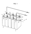
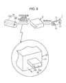
- Figs. 1 to 6 illustrate an electrically conductive connecting member 1 according to a first embodiment of the present invention.
- the electrically conductive connecting member 1 is incorporated as one electrode of a battery 2.
- a plurality of battery cells 2 can be connected in series to form an assembled battery 4. That is, each battery cell 2 is connected via an electrically conductive connecting member 1 serving as an electrode of a plus output terminal (plus output side) thereof to a minus output terminal (minus output side) of another battery cell 2.
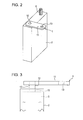
- Each battery cell 2 is a lithium-ion battery, and a plus output terminal (plus output side) thereof is formed of aluminum or an aluminum alloy.
- a positive-electrode carrier 5 provided in the battery cell 2 (a base body for fixing electrons and ions) is formed of aluminum or an aluminum alloy and the plus output terminal provided integrally with or separately from the positive-electrode carrier 5 with continuity is formed of aluminum or an aluminum alloy.
- a minus output terminal of the battery cell 2 is formed of copper or a copper alloy.
- a minus terminal 6 protrudes upward from an upper end of the battery cell 2. An outer peripheral surface of the minus terminal 6 is threaded externally.
- the electrically conductive connecting member 1 (electrode) of the present invention includes a columnar bar-shaped section 10 (electrode section), and a band-plate-shaped section 11 (bus bar section) that is connected to one end of the bar-shaped section 10 and extends in a direction away from an axial center of the bar-shaped section 10.
- An axial direction of the bar-shaped section 10 and a plate-surface extending direction of the band-plate-shaped section 11 are orthogonal to each other.
- a connecting portion between the bar-shaped section 10 and the band-plate-shaped section 11 has a structure such that the band-plate-shaped section 11 is fitted on the one end of the bar-shaped section 10 (the one end of the bar-shaped section 10 penetrates through the band-plate-shaped section 11).
- an end of the bar-shaped section 10 connected to the band-plate-shaped section 11 and penetrating through the band-plate-shaped section 11 is flush with a surface of the band:plate-shaped section 11.
- the bar-shaped section 10 penetrating through the band-plate-shaped section 11 may further slightly protrude from the band-plate-shaped section 11.
- the bar-shaped section 10 is shaped like a round bar, and the band-plate-shaped section 11 is shaped like a rectangular plate round-chamfered at four corners in plan view.
- the thickness of the bar-shaped section 10 is substantially constant. and the thickness of the band-plate-shaped section 11 is substantially constant.
- the band-plate-shaped section 11 has a raised portion 12 that surrounds the root of the bar-shaped section 10.
- the raised portion 12 is raised by the influence of the edge shape of a cutting tool during a procedure for producing the electrically conductive connecting member 1 (cutting step), and has a round concave face provided all around its circumference.
- An end of the band-plate-shaped section 11 opposite a side of the bar-shaped section 10 has a connecting hole 13 provided through the band-plate-shaped section 11 in a plate thickness direction.
- the raised portion 12 is not always necessary as a structure of the electrically conductive connecting member 1. However, the raised portion 12 is effective in reinforcing a protruding state of the bar-shaped section 10 from the band-plate-shaped section 11 and in being used as an index of the amount by which the band-plate-shaped section 11 floats from the battery cell 2 (ensuring a floating state) when the electrically conductive connecting member 1 is attached to the battery cell 2.
- the outer diameter of the bar-shaped section 10 is set at 5 to 25 mm, and the protruding length of the bar-shaped section 10 from the band-plate-shaped section 11 is set at 10 to 100 mm.
- the inner diameter of the connecting hole 13 provided in the band-plate-shaped section 11 is set to be suitable to receive the minus terminal 6 provided on the battery cell 2 (nominal diameter is about 4 to 12 mm). While the dimensions of the band-plate-shaped section 11 can be appropriately changed according to the connection distance between battery cells 2 and the amount of current, for example, for example, the long side length is 30 to 70 mm, the short side length is 20 to 60 mm, and the thickness is 1 to 2 mm.
- the bar-shaped section 10 and the band-plate-shaped section 11 are formed of different kinds of metals. As described above, when the electrically conductive connecting member 1 of the present invention is adopted for the plus output terminal of the battery cell 2, the bar-shaped section 10 is formed of the same metal as that for the positive-electrode carrier 5 and the plus output terminal of the battery cell 2, that is, formed of aluminum or an aluminum alloy.
- the band-plate-shaped section 11 is formed of the same metal as that for a negative-electrode carrier, the minus output terminal, and the minus terminal 6 of the battery cell 2, that is, formed of copper or a copper alloy.
- An outer peripheral surface of a portion of the bar-shaped section 10 extending through the band-plate-shaped section 11 and an inner peripheral surface of a portion of the band-plate-shaped section 11 fitted on the bar-shaped section 10 are subjected to diffusion bonding.
- the term diffusion bonding refers to a state in which the metal (Al) of the bar-shaped section 10 and the metal (Cu) of the band-plate-shaped section 11 are deformed under ultrahigh pressure (e.g., about 1000 MPa) to form a binding interface where the metals are in tight contact with each other on the metal tissue level, and as a result, electrical conductivity and mechanical binding structure are increased to "values practically suitable for the electrically conductive connecting member 1."
- ultrahigh pressure e.g., about 1000 MPa
- the portion of the bar-shaped section 10 protruding from the band-plate-shaped section 11 is used as an internal connecting portion 15. That is, the internal connecting portion 15 is electrically connected to the plus output terminal of the battery cell 2 (a portion provided integrally with or separately from the positive-electrode carrier 5). Further, the connecting hole 13 provided in the band-plate-shaped section 11 is fitted on a minus terminal 6 of a battery cell 2 to be connected, and a copper nut 16 (see Fig. 1 ) formed of the same metal as that for the band-plate-shaped section 11 is screwed on the protruding minus terminal 6 (externally threaded portion).
- the minus terminal 6 may be inserted in the connecting hole 13 of the band-plate-shaped section 11 and the minus terminal 6 and the connecting hole 13 may then be welded together. In this case, since the portions of the same metal are welded, no electrical and mechanical problems occur.
- the bar-shaped section 10 (internal connecting portion 15) of the electrically conductive connecting member 1 and the plus output terminal (portion formed integrally with or separately from the positive-electrode carrier 5) of the battery cell 2 are connected by connection of the same metal, and therefore, electrolytic corrosion does not occur.
- the band-plate-shaped section 11 (the inner surface of the connecting hole 13 serving as an external connecting portion) of the electrically conductive connecting member 1, and the outer surface of the minus terminal 6 of the battery cell 2 and the nut 16 are also connected by connection of the same metal. Hence, electrolytic corrosion does not occur.
- the bar-shaped section 10 and the band-plate-shaped section 11 of the electrically conductive connecting member 1 are formed of different metals, they are diffusion-bonded, and therefore, electrolytic corrosion does not occur. Also, the bar-shaped section 10 and the band-plate-shaped section 11 are kept in a state in which the electric resistance is suppressed.
- the electrically conductive connecting member 1 of the present invention As results of these, in the assembled battery 4 formed by connecting a plurality of battery cells 2 in series by the electrically conductive connecting member 1 of the present invention, electrolytic corrosion does not occur in any connecting portion, and high-efficiency conductivity is ensured. Further, since the electrically conductive connecting member 1 has excellent mechanical strength, it does not bend or break in a normal use condition.
- the bar-shaped section 10 is lightweight because it is formed of aluminum or an aluminum alloy, and this can reduce the weight of the assembled battery 4. For this reason, the first embodiment is useful in weight reduction of an electric car in which the assembled battery 4 is mounted as a battery.
- extrusion is performed under high or ultrahigh hydrostatic pressure, as illustrated in Fig. 6 .
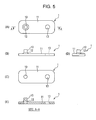
- An extrusion device 20 used for extrusion includes a single-opening die 21 (dice) corresponding to a planar shape of a band-plate-shaped section 11 to be obtained (see Fig. 5(A) ), and can perform extrusion in an isotropic pressure environment under ultrahigh pressure (up to about 1000 MPa).
- a positive-electrode blank 10A metal blank formed of the same metal (aluminum or an aluminum alloy) as that for a positive-electrode carrier 5 and a plus output terminal of a battery cell 2 is prepared in a bar form.
- a negative-electrode blank 11A metal blank formed of the same metal (copper or a copper alloy) as that for a negative-electrode carrier, a minus output terminal, and a minus terminal 6 of the battery cell 2 is prepared in a band form.
- a billet (composite blank) 1A entirely shaped like a thick round bar is prepared by winding the negative-electrode blank 11A around the bar-shaped positive-electrode blank 10A. At this time, the bar-shaped positive-electrode blank 10A is set to be shifted from the center portion of the thick round bar of the billet 1A.
- the negative-electrode blank 11A may be shaped like a hollow pipe in which the bar-shaped positive-electrode blank 10A can be eccentrically inserted, and the positive-electrode blank 10A may be inserted in the negative-electrode blank 11A to form the billet 1A.
- the billet 1A is loaded in the extrusion device 20, and the extrusion device 20 is started in an isotropic pressure environment under ultrahigh pressure (up to 1000 MPa). Since the billet 1A is structured by winding the negative-electrode blank 11A around the positive-electrode blank 10A. as described above, the positive-electrode blank 10A and the negative-electrode blank 11A are pushed out in parallel (subjected to extrusion or drawing), and a molded part 1B is obtained in which the positive-electrode blank 10A and the negative-electrode blank 11A are integrated by diffusion bonding.
- the opening area of the die 21 of the extrusion device 20 is smaller than the cross-sectional area of the billet 1A, when the billet 1A is passed through the die 21, it is compressed all around its circumference to plastically deform. After coming out of the die 21, a joint surface between the positive-electrode blank 10A and the negative-electrode blank 11A forms "an interface (diffusion-bonded portion) between an outer peripheral surface of a bar-shaped section 10 and an inner peripheral surface of a band-plate-shaped section 11.”
- the molded part 1B thus obtained is cut at a predetermined interval in an extruding direction. Since the die 21 of the extrusion device 20 has the opening shaped correspondingly to the planar shape of the band-plate-shaped section 11 (see Fig. 5(A) ) in the first embodiment, the cutting interval of the molded part 1B is set in accordance with the length of the bar-shaped section 10, which corresponds to the height of the electrically conductive connecting member 1.
- the negative-electrode blank 11A is subjected to cutting (milling) to a thickness of a band-plate-shaped section 11. Thereby, a band-plate-shaped section 11 is formed, and the positive-electrode blank 10A remains in a protruding state to form a bar-shaped section 10 and a raised portion 12 provided around the root of the bar-shaped section 10. Further, the portion having the thickness of the band-plate-shaped section 11 is subjected to boring to form a connecting hole 13, whereby an electrically conductive connecting member 1 is completed. Surface polishing or surface treatment may be performed as needed.
- the electrically conductive connecting member 1 thus produced is formed by integrating the bar-shaped section 10 formed of the same metal as that for the positive-electrode carrier 5 of the battery cell 2 and the band-plate-shaped section 11 formed of the same metal as that for the minus terminal 6 of the battery cell 2 through diffusion bonding. Hence, electrolytic corrosion does not occur and electric resistance is reduced in any portion of the electrically conductive connecting member 1. Moreover, the mechanical strength is excellent.
- the shapes and outer dimensions of the bar-shaped section 10 and the band-plate-shaped section 11 are not limited.
- the connecting strength of the band-plate-shaped section 11 may be increased by enlarging a portion around the connecting hole 13 in a plate surface direction.
- the four corners of the band-plate-shaped section 11 may be subjected to angular chamfering instead of round chamfering, or chamfering may be omitted (angular corners may be formed).
- the band-plate-shaped section 11 may be entirely shaped like a long circle in plan view.
- the bar-shaped section 10 can be shaped like a square bar.
- Figs. 8 and 9 illustrate an electrically conductive connecting member 1 according to a second embodiment of the present invention.
- an embedded material 30 is embedded in a center portion of a band-plate-shaped section 11 in a plate thickness direction.
- the electrically conductive connecting member 1 of the second embodiment is also adopted for a plus output terminal of a battery cell 2 (see Figs. 1 and 2 ).
- a bar-shaped section 10 is formed of the same metal (aluminum or an aluminum alloy) as that for a positive-electrode carrier 5 and the plus output terminal of the battery cell 2
- the band-plate-shaped section 11 is formed of the same metal (copper or a copper alloy) as that for a positive-electrode carrier and a plus output terminal of the battery cell 2.
- a connecting hole 13 which penetrates through the band-plate-shaped section 11 in the plate thickness direction, is provided in an end portion of the band-plate-shaped section 11 opposite a side where the bar-shaped section 10 is provided. This point is also identical to that of the second embodiment.
- the embedded material 30 is arranged at a position that is aligned with a portion of the band-plate-shaped section 11 to which the bar-shaped section 10 is connected (a position where the bar-shaped section 10 and the embedded material 30 overlap with each other in plan view). This embedded material 30 is provided not to reach the position of the connecting hole 13. However, specific dimensions of the embedded material 30 (e.g., shape and size in plan view, and thickness) are not limited particularly.
- the embedded material 30 is formed of the same metal as that for the bar-shaped section 10. That is, the embedded material 30 is formed of the same metal as that for the positive-electrode carrier 5 and the plus output terminal of the battery cell 2, more specifically, aluminum or an aluminum alloy.
- the band-plate-shaped section 11 has a recess 32 that surrounds the bar-shaped section 10 in the portion to which the bar-shaped section 10 is connected.
- An upper face of the embedded material 30 is exposed in a bottom portion of the recess 32.
- the recess 32 may be formed by slightly digging the upper face of the embedded material 30. In any case, the bottom portion of the recess 32 is formed by the embedded material 30.
- the aperture size of the recess 32 is preferably set to fit in the size of the embedded material 30 in plan view.
- the bottom portion of the recess 32 that is, the upper face of the embedded material 30 exposed in the recess 32 is provided with a raised portion 33 that surrounds the root of the bar-shaped section 10.
- the raised portion 33 is a filling portion (e.g., beads, a base material, or a welding material) to be produced in a welding process when the bar-shaped section 10 is connected to the embedded material 30 by welding.
- a fitting hole or a fitting recess for the bar-shaped section 10 is formed in the embedded material 30 before welding, positioning and holding can be easily and reliably performed during welding.
- the raised portion 33 is effective in reinforcing a state in which the bar-shaped section 10 protrudes from the band-plate-shaped section 11 (embedded material 30).
- the raised portion 33 is received in the recess 32, but does not protrude from the surface of the band-plate-shaped section 11. In other words, it is useful to form the recess 32 when the bar-shaped section 10 is connected to the band-plate-shaped section 11 (embedded material 30), because the raised portion 33 does not protrudes outside.
- An outer peripheral surface of the embedded material 30 and an inner peripheral surface of the band-plate-shaped section 11 are diffusion-bonded by die working under ultrahigh isotropic pressure. While the bar-shaped section 10 and the embedded material 30 are connected by welding, as described above, since the embedded material 30 and the bar-shaped section 10 are both formed of aluminum or an aluminum alloy, that is, formed of the same metal, an eutectic is not produced in a welded portion therebetween. Thus, electrolytic corrosion does not occur and the electric resistance is kept suppressed. Moreover, the mechanical strength is sufficient, and there is no problem.
- extrusion is performed under ultrahigh hydrostatic pressure similarly to the first embodiment, as illustrated in Fig. 9 .
- an extrusion device 20 used for extrusion includes a single-opening die 21 corresponding to a front shape of a band-plate-shaped section 11 to be obtained (see Fig. 5(B) illustrating the first embodiment).
- the extrusion device 20 can perform extrusion in an isotropic pressure environment under ultrahigh pressure (up to about 1000 MPa).
- a positive-electrode blank 30A (metal blank) formed of the same metal as that for a bar-shaped section 10 is prepared, for example, in the form of a bar of elliptic cross section. Since the bar-shaped section 10 is formed of the same metal (aluminum or an aluminum alloy) as that for a positive-electrode carrier 5 and a plus output terminal of a battery cell 2, the positive-electrode blank 30A is also ultimately formed of the same metal as that for the positive-electrode carrier 5 and the plus output terminal of the battery cell 2.
- a negative-electrode blank 11A (metal blank) formed of the same metal (copper or a copper alloy) as that for a negative-electrode carrier, a minus output terminal, and a minus terminal 6 of the battery cell 2 is prepared in a band form.
- a billet (composite blank) 1A entirely shaped like a thick round bar is prepared by winding the negative-electrode blank 11A around the bar-shaped positive-electrode blank 30A.
- the bar-shaped positive-electrode blank 30A is set to be shifted from the center portion of the thick round bar of the billet 1A.
- the billet 1A is loaded in the extrusion device 20, and the extrusion device 20 is started in an isotropic pressure environment under ultrahigh pressure (up to 1000 MPa). Since the billet 1A is structured by winding the negative-electrode blank 11A around the positive-electrode blank 30A, as described above, the positive-electrode blank 30A and the negative-electrode blank 11A are pushed out in parallel (subjected to extrusion or drawing), and a molded part 1B is obtained in which the positive-electrode blank 30A and the negative-electrode blank 11A are integrated through diffusion bonding.
- the opening area of the die 21 of the extrusion device 20 is smaller than the cross-sectional area of the billet 1A, when the billet 1A is passed through the die 21, it is compressed all around its circumference to plastically deform. After coming out of the die 21, a joint surface between the blanks 30A and 11A forms "an interface (diffusion-bonded portion) between an outer peripheral surface of an embedded material 30 and an inner peripheral surface of a band-plate-shaped section 11.”
- the molded part 1B thus obtained is cut at a predetermined interval in an extruding direction.
- the cutting interval of the molded part 1B corresponds to a size of a short side (width) of a rectangle of the band-plate-shaped section 11 in plan view.
- a portion of the bar-shaped negative-electrode blank 11A near one longitudinal end is subjected to cutting (milling) to form a recess 32 (a recess of a depth that allows an upper surface of an embedded material 30 to be exposed), and a portion near the other longitudinal end is subjected to boring to form a connecting hole 13, whereby a band-plate-shaped section 11 is formed.
- a positive-electrode blank 10A shaped like a round bar and formed of the same metal (aluminum or an aluminum alloy) blank (metal blank) as that for the positive-electrode carrier 5 and the plus output terminal of the battery cell 2 is prepared, and the positive-electrode blank 10A (that is, a member to be a bar-shaped section 10) is connected to the embedded material 30 exposed in the recess 32 of the band-plate-shaped section 11 by welding. In this way, an electrically conductive connecting member 1 is completed. Surface polishing or surface treatment may be performed as needed.
- the bar-shaped section 10 and the band-plate-shaped section 11 are diffusion-bonded with the embedded material 30 electrically combined with the bar-shaped section 10 being disposed therebetween. That is, in the electrically conductive connecting member 1 of the second embodiment, the bonding area (contact area) of the diffusion-bonded portion is increased by the presence of the embedded material 30, compared with the electrically conductive connecting member 1 of the first embodiment in which the bar-shaped section 10 and the band-plate-shaped section 11 are directly diffusion-bonded.
- the electrically conductive connecting member 1 of the second embodiment is more suitable for conduction of large current than the electrically conductive connecting member 1 of the first embodiment.
- Figs. 10 and 11 illustrate an electrically conductive connecting member 1 according to a third embodiment of the present invention.
- the electrically conductive connecting member 1 of the third embodiment is substantially similar to the second embodiment (see Fig. 8 ), and an embedded material 30 is embedded in a center portion in a plate thickness direction of a band-plate-shaped section 11, as illustrated in Fig. 10 .
- the greatest difference of the electrically conductive connecting member 1 of the third embodiment from the second embodiment is that the embedded material 30 is embedded in the overall longitudinal direction of the entire band-plate-shaped section 11. That is, the embedded material 30 reaches both a portion where a bar-shaped section 10 is connected to the band-plate-shaped section 11 and a position where a connecting hole 13 is formed.
- the third embodiment is identical to the second embodiment in that the embedded material 30 is formed of the same metal (aluminum or an aluminum alloy) as that for the bar-shaped section 10 and in that a recess 32 is provided in the band-plate-shaped section 11 and the bar-shaped section 10 is connected to the embedded material 30 that forms a bottom of the recess 32 by welding.
- the embedded material 30 is formed of the same metal (aluminum or an aluminum alloy) as that for the bar-shaped section 10 and in that a recess 32 is provided in the band-plate-shaped section 11 and the bar-shaped section 10 is connected to the embedded material 30 that forms a bottom of the recess 32 by welding.
- the electrically conductive connecting member 1 of the third embodiment is produced in a manner similar to that adopted in the second embodiment except that a positive-electrode blank 30A (metal blank) for forming the embedded material 30 is prepared in a round bar form and a negative-electrode blank 11A is wound around the positive-electrode blank 30A to form a billet (composite blank) 1A that is shaped like a thick round bar entirely formed by two concentric circles.
- a positive-electrode blank 30A metal blank
- a negative-electrode blank 11A is wound around the positive-electrode blank 30A to form a billet (composite blank) 1A that is shaped like a thick round bar entirely formed by two concentric circles.
- the electrically conductive connecting member 1 of the third embodiment since the size of the embedded material 30 is larger than in the electrically conductive connecting member 1 of the second embodiment, the bonding area (contact area) of a diffusion-bonded portion is increased. Hence, the electrically conductive connecting member 1 of the third embodiment is more suitable for conduction of large current.
- the embedded material 30 is exposed in an inner peripheral surface of the connecting hole 13 provided in the band-plate-shaped section 11.
- a minus terminal 6 of a battery cell 2 When a minus terminal 6 of a battery cell 2 is inserted in the connecting hole 13, it is brought into contact with the embedded material 30.
- the minus terminal 6 inserted in the connecting hole 13 is also reliably in contact with the band-plate-shaped section 11 that clamps the embedded material 30 from both front and back sides. For this reason, continuity is ensured between the band-plate-shaped section 11 and the minus terminal 6 that are formed of the same metal and have low electric resistance, and there is no problem.
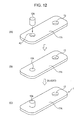
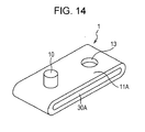
- Figs. 12(A) to 12(C) illustrate an electrically conductive connecting member 1 according to a fourth embodiment of the present invention.
- the electrically conductive connecting member 1 of the fourth embodiment is substantially identical to the electrically conductive connecting member 1 of the first embodiment (see Fig. 4 ) in appearance (a band-plate-shaped section 11 is shaped like a completely flat plate, but does not have a raised portion 12 that surrounds the root of a bar-shaped section 10).
- the electrically conductive connecting member 1 of the fourth embodiment is characterized in a production method therefor.
- a negative-electrode blank 11A metal blank
- a positive-electrode blank 10A metal blank
- the negative-electrode blank 11A is formed of the same metal (copper or a copper alloy) as that for a negative-electrode carrier, a minus output terminal, and a minus terminal 6 of a battery cell 2 (see Fig. 1 ), and is shaped in an outer form as the band-plate-shaped section 11 (a rectangular plate having round-chamfered four corners).
- An attachment hole 45 to which the positive-electrode blank 10A is to be connected is provided in a portion near one longitudinal end of the negative-electrode blank 11A, and a connecting hole 13 is provided in a portion near the other longitudinal end.
- the opening area of the attachment hole 45 is smaller than the cross-sectional area of the bar-shaped section 10 (positive-electrode blank 10A).
- the positive-electrode blank 10A is formed of the same metal (aluminum or an aluminum alloy) as that for a positive-electrode carrier 5 and a plus output terminal of the battery cell 2 (see Fig. 1 ), and is shaped in an outer form (round bar form) as the bar-shaped section 10.
- the positive-electrode blank 10A is press-fitted in the attachment hole 45 of the negative-electrode blank 11A. Press-fitting is performed so that the positive-electrode blank 10A is held protruding from the negative-electrode blank 11A.
- the positive-electrode blank 10A is press-fitted from one side of the attachment hole 45 to protrude to the other side of the attachment hole 45 (so that the positive-electrode blank 10A temporarily passes through the attachment hole 45 in almost the entire length).
- the positive-electrode blank 10A held protruding from the attachment hole 45 forms a bar-shaped section 10, and an electrically conductive connecting member 1 can be completed.
- Surface polishing or surface treatment may be performed as needed.
- the negative-electrode blank 11A and the positive-electrode blank 10A are plastically deformed in the radial direction and in the press-fitting direction between an inner peripheral surface of the attachment hole 45 and an outer peripheral surface of the bar-shaped section 10.
- an interface between the inner peripheral surface of the attachment hole 45 and the outer peripheral surface of the bar-shaped section 10 forms "a diffusion-bonded portion.”
- the bar-shaped section 10 formed of the same metal as that for the positive-electrode carrier 5 of the battery cell 2 and the band-plate-shaped section 11 formed of the same metal as that for the minus terminal 6 of the battery cell 2 are integrated through diffusion bonding. Hence, electrolytic corrosion does not occur and electric resistance can be reduced in any portion of the electrically conductive connecting member 1. Moreover, mechanical strength is high.
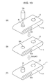
- Figs. 13(A) to 13(C) illustrate an electrically conductive connecting member 1 according to a fifth embodiment of the present invention.
- the electrically conductive connecting member 1 of the fifth embodiment is substantially identical to the electrically conductive connecting member 1 of the second embodiment (see Fig. 8 ) in appearance, and an embedded material 30 is embedded in a center portion of a band-plate-shaped section 11 in a plate thickness direction to be aligned with a portion to which a bar-shaped section 10 is to be connected.
- the embedded material 30 is provided not to reach a position where a connecting hole 13 is to be formed (the band-plate-shaped section 11 does not have a recess 32 that surrounds the root of the bar-shaped section 10).
- a billet (composite blank) 1A shaped like a thick round bar in which a positive-electrode blank 30A is eccentrically provided is obtained by winding a negative-electrode blank 11A around the positive-electrode blank 30A, the billet 1A is subjected to extrusion or drawing with an extrusion device 20 capable of extrusion under a ultrahigh hydrostatic pressure, and a molded part 1B is formed in which the positive-electrode blank 30A and the negative-electrode blank 11A are integrated through diffusion bonding.
- the molded part 1B thus obtained is cut to a dimension of a short side of a rectangle of the band-plate-shaped section 11 in plan view.
- an attachment hole 45 to which the positive-electrode blank 10A is to be connected is formed in a portion of the band-plate-shaped negative-electrode blank 11A near one longitudinal end, and a connecting hole 13 is formed in a portion near the other longitudinal end.
- the opening area of the attachment hole 45 is set to be smaller than the cross-sectional area of a bar-shaped section 10 (positive-electrode blank 10A).
- the positive-electrode blank 10A is press-fitted in the attachment hole 45 of the negative-electrode blank 11A so as to be held protruding from the negative-electrode blank 11A, as illustrated in Fig. 13(B) .
- a bar-shaped section 10 is formed by the positive-electrode blank 10A held protruding from the attachment hole 45, and an electrically conductive connecting member 1 can be completed. Surface polishing or surface treatment may be performed as needed.
- an electrically conductive connecting member 1 in which an embedded material 30 is embedded in almost the entire band-plate-shaped section 11 can also be produced, similarly to the electrically conductive connecting member 1 of the third embodiment (see Fig. 10 ).
- the bar-shaped section 10 is in contact with the band-plate-shaped section 11. Since the bar-shaped section 10 is also reliably in contact with the embedded material 30 of the same metal, electrical continuity can be ensured reliably.
- the electrically conductive connecting member 1 used as the plus output terminal is illustrated in the first to fifth embodiments, it may be adopted as the minus output terminal.
- the bar-shaped section 10 is formed of the same metal (copper or a copper alloy) as that for the negative-electrode carrier of the battery cell 2
- the band-plate-shaped section 11 is formed of the same metal (aluminum or an aluminum alloy) as that for the positive-electrode carrier 5 of the battery cell 2.
- the embedded material 30 when the embedded material 30 is adopted, it is formed of the same metal (copper or a copper alloy) as that for the negative-electrode carrier of the battery cell 2, similarly to the bar-shaped section 10.
- the electrically conductive connecting member 1 of the present invention is extremely suitable for connection of a car-mounted lithium ion battery, it can be used for connection of a lithium ion battery (battery) in other use without any problem.
- the connecting hole 13 does not always need to be formed in the band-plate-shaped section 11.
- a projecting bar section to be connected to the output terminal of a polarity different from that of the output terminal connected to the bar-shaped section 10 can be provided integrally with the band-plate-shaped section 11.
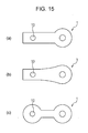
- the planar shape of the electrically conductive connecting member 1, that is, the planar shape of the band-plate-shaped section 11 is not limited to the rectangular shape. As illustrated in Figs. 15(a) to 15(c) , various shapes, such as a spoon shape, a paddle shape, and a gourd shape, can be adopted.
- a high-performance and high-reliability electrically conductive connecting member that is suitable for a battery including a plus output terminal and a minus output terminal formed of different metals, that can suppress electric resistance while preventing electrolytic corrosion, and that is excellent in mechanical strength.
- this electrically conductive connecting member can be used alone for various batteries, it is possible to produce a battery in which the electrically conductive connecting member of the present invention is assembled as one electrode beforehand and to offer the battery including the electrically conductive connecting member to a market.
Landscapes
- Chemical & Material Sciences (AREA)
- Chemical Kinetics & Catalysis (AREA)
- Electrochemistry (AREA)
- General Chemical & Material Sciences (AREA)
- Engineering & Computer Science (AREA)
- Mechanical Engineering (AREA)
- Inorganic Chemistry (AREA)
- Manufacturing & Machinery (AREA)
- Materials Engineering (AREA)
- Connection Of Batteries Or Terminals (AREA)
Applications Claiming Priority (2)
| Application Number | Priority Date | Filing Date | Title |
|---|---|---|---|
| JP2010232448A JP5570383B2 (ja) | 2010-10-15 | 2010-10-15 | 導電性連結部材、導電性連結部材の製造方法、及び導電性連結部材が電極とされたバッテリ |
| PCT/JP2011/073587 WO2012050173A1 (fr) | 2010-10-15 | 2011-10-13 | Élément de connexion conducteur de l'électricité, procédé de fabrication d'élément de connexion conducteur de l'électricité et batterie équipée de l'élément de connexion conducteur de l'électricité en tant qu'électrode |
Publications (3)
| Publication Number | Publication Date |
|---|---|
| EP2581966A1 true EP2581966A1 (fr) | 2013-04-17 |
| EP2581966A4 EP2581966A4 (fr) | 2014-01-15 |
| EP2581966B1 EP2581966B1 (fr) | 2016-08-31 |
Family
ID=45938394
Family Applications (1)
| Application Number | Title | Priority Date | Filing Date |
|---|---|---|---|
| EP11832604.0A Active EP2581966B1 (fr) | 2010-10-15 | 2011-10-13 | Élément de connexion conducteur de l'électricité, procédé de fabrication d'élément de connexion conducteur de l'électricité et batterie équipée de l'élément de connexion conducteur de l'électricité en tant qu'électrode |
Country Status (10)
| Country | Link |
|---|---|
| US (1) | US9136617B2 (fr) |
| EP (1) | EP2581966B1 (fr) |
| JP (1) | JP5570383B2 (fr) |
| KR (2) | KR101765379B1 (fr) |
| CN (1) | CN103003979B (fr) |
| ES (1) | ES2592514T3 (fr) |
| HU (1) | HUE030693T2 (fr) |
| PL (1) | PL2581966T3 (fr) |
| TW (1) | TWI469427B (fr) |
| WO (1) | WO2012050173A1 (fr) |
Cited By (6)
| Publication number | Priority date | Publication date | Assignee | Title |
|---|---|---|---|---|
| EP2667429A1 (fr) * | 2012-05-25 | 2013-11-27 | Hitachi Vehicle Energy, Ltd. | Cellules électriques et batterie assemblée |
| DE102013220284A1 (de) * | 2013-10-08 | 2015-04-09 | Engeser Gmbh Innovative Verbindungstechnik | Verfahren zur Herstellung einer elektrischen Verbindung sowie Batteriezellkontakt |
| CN105103337A (zh) * | 2013-07-05 | 2015-11-25 | Lg化学株式会社 | 包括由不同金属组成的连接构件的电池模块 |
| US9252550B2 (en) | 2012-12-28 | 2016-02-02 | Hitachi Metals, Ltd. | Electrode terminal connector producing method |
| WO2016110369A1 (fr) * | 2015-01-08 | 2016-07-14 | Raimund Huber | Composant fonctionnel électrique à broche de contact et procédé de fabrication d'un composant fonctionnel électrique |
| EP2850674B1 (fr) * | 2012-05-18 | 2023-03-29 | Robert Bosch GmbH | Procédé pour relier deux pôles de deux cellules de batterie constitués de matériaux différents ainsi qu'unité de batterie |
Families Citing this family (29)
| Publication number | Priority date | Publication date | Assignee | Title |
|---|---|---|---|---|
| KR20120138790A (ko) * | 2010-03-29 | 2012-12-26 | 가부시키가이샤 고베 세이코쇼 | 버스 바 및 버스 바의 제조 방법 |
| US9553294B2 (en) | 2011-12-16 | 2017-01-24 | Gs Yuasa International Ltd. | Electric storage device, manufacturing method of electric storage device, and bus bar used for electric storage device |
| JP5929733B2 (ja) * | 2012-12-10 | 2016-06-08 | 株式会社豊田自動織機 | 蓄電モジュール及び二次電池モジュール |
| JP2014130740A (ja) * | 2012-12-28 | 2014-07-10 | Hitachi Metals Ltd | 電極端子接続体の製造方法 |
| JP2014143158A (ja) * | 2012-12-28 | 2014-08-07 | Hitachi Metals Ltd | 電極端子接続体の製造方法 |
| KR101590986B1 (ko) * | 2013-03-05 | 2016-02-03 | 주식회사 엘지화학 | 확산 접합을 이용한 전극단자 또는 버스 바의 접합 방법 |
| US9831482B2 (en) * | 2013-09-06 | 2017-11-28 | Johnson Controls Technology Company | Battery module lid system and method |
| JP6616058B2 (ja) * | 2014-01-28 | 2019-12-04 | 住友電装株式会社 | 端子及び該端子のアルミ電線接続構造 |
| CN104117776B (zh) * | 2014-07-17 | 2016-04-13 | 大族激光科技产业集团股份有限公司 | 高反射金属部件的激光焊接方法 |
| KR101741704B1 (ko) | 2014-12-01 | 2017-05-30 | 최범진 | 배터리 팩의 단자 연결 유닛 및 그에 의한 배터리 팩의 연결 방법 |
| US10403875B2 (en) * | 2015-04-14 | 2019-09-03 | Ford Global Technologies, Llc | Busbar assembly for vehicle traction battery |
| KR102490863B1 (ko) | 2015-11-04 | 2023-01-20 | 삼성에스디아이 주식회사 | 이차전지의 제조방법 |
| DE102016202873A1 (de) * | 2016-02-24 | 2017-08-24 | Bayerische Motoren Werke Aktiengesellschaft | Verfahren zur Herstellung eines elektrischen Verbindungselements und Verbindungselement für Batteriezellen |
| CA2921925A1 (fr) | 2016-02-25 | 2017-08-25 | Hydro-Quebec | Assemblage d'accumulateurs electriques |
| KR102742694B1 (ko) * | 2016-05-30 | 2024-12-16 | 삼성에스디아이 주식회사 | 배터리 모듈 |
| EP3465799B1 (fr) | 2016-06-01 | 2021-04-21 | Termaco Ltee | Connecteur de batterie |
| KR101913250B1 (ko) | 2017-01-13 | 2018-12-31 | 안동대학교 산학협력단 | 전극 연결 태그 및 이를 구비한 이차전지 패키지 |
| JP6741215B2 (ja) * | 2017-01-20 | 2020-08-19 | 株式会社オートネットワーク技術研究所 | 接続モジュール |
| CN107538124B (zh) * | 2017-09-26 | 2021-03-16 | 东莞市大为工业科技有限公司 | 一种锂电池复合电极的扩散连接方法 |
| US11196129B2 (en) * | 2017-12-22 | 2021-12-07 | Panasonic Intellectual Property Management Co., Ltd. | Cell laminate |
| CN109623060A (zh) * | 2018-12-03 | 2019-04-16 | 合肥晶澳太阳能科技有限公司 | 一种光伏组件接线盒的焊接方法 |
| KR102450418B1 (ko) | 2018-12-07 | 2022-09-30 | 주식회사 엘지에너지솔루션 | 안전성이 개선된 배터리 모듈, 이러한 배터리 모듈을 포함하는 배터리 팩 및 이러한 배터리 팩을 포함하는 자동차 |
| KR102691428B1 (ko) | 2018-12-13 | 2024-08-01 | 주식회사 엘지에너지솔루션 | 전지 모듈 |
| USD928088S1 (en) * | 2019-02-27 | 2021-08-17 | A.F.W. Co., Ltd. | Bus bar for fuses |
| DE102019203166A1 (de) * | 2019-03-08 | 2020-09-10 | Zf Friedrichshafen Ag | Verbindung einer Stromschiene mit einem weiteren stromführenden Element |
| CN111384607A (zh) * | 2020-03-20 | 2020-07-07 | 重庆中科超容科技有限公司 | 分体便拆式汇流排 |
| KR102895044B1 (ko) | 2020-04-13 | 2025-12-02 | 주식회사 엘지에너지솔루션 | 전지 모듈 및 그 제조 방법 |
| CN112563671B (zh) * | 2020-12-16 | 2024-06-11 | 张家港华捷电子有限公司 | 锂电保护板与电池组的连接结构 |
| CN218731641U (zh) * | 2022-11-03 | 2023-03-24 | 湖北亿纬动力有限公司 | 汇流排、电池包及电子设备 |
Family Cites Families (27)
| Publication number | Priority date | Publication date | Assignee | Title |
|---|---|---|---|---|
| GB2299701B (en) * | 1995-04-07 | 1997-10-15 | Paul Philip Stockton | Cellular battery |
| CA2274483C (fr) * | 1997-10-07 | 2006-01-31 | Matsushita Electric Industrial Co., Ltd. | Batterie secondaire electrolytique non aqueuse |
| JP4146000B2 (ja) * | 1998-08-31 | 2008-09-03 | 松下電器産業株式会社 | 電池間接続構造 |
| US6844110B2 (en) | 2000-05-24 | 2005-01-18 | Ngk Insulators, Ltd. | Lithium secondary cell and assembly thereof |
| JP2002151045A (ja) * | 2000-11-10 | 2002-05-24 | Honda Motor Co Ltd | 電池モジュール用バスバーおよび電池モジュール |
| JP2002358945A (ja) * | 2000-11-15 | 2002-12-13 | Ngk Insulators Ltd | リチウム二次単電池の接続構造体 |
| JP4029585B2 (ja) | 2001-06-18 | 2008-01-09 | 日産自動車株式会社 | バスバーおよびバスバーを用いた電池 |
| JP2003123733A (ja) | 2001-10-18 | 2003-04-25 | Sony Corp | 電池用電極及びリチウムイオンポリマ電池、並びにそれらの製造方法 |
| JP2003163039A (ja) | 2001-11-27 | 2003-06-06 | Yazaki Corp | バスバーの接続構造 |
| CN101218697B (zh) * | 2005-07-05 | 2010-12-08 | 松下电器产业株式会社 | 电池间连接装置 |
| JP2007134233A (ja) * | 2005-11-11 | 2007-05-31 | Toyota Motor Corp | 電池端子構造 |
| JP2007280898A (ja) | 2006-04-12 | 2007-10-25 | Toyota Motor Corp | 端子接続構造および蓄電機構ならびに電動車両 |
| JP4416770B2 (ja) * | 2006-09-07 | 2010-02-17 | 日立ビークルエナジー株式会社 | 組電池 |
| JP2010103053A (ja) * | 2008-10-27 | 2010-05-06 | Toyota Motor Corp | 電池モジュールおよび電池モジュールの製造方法 |
| JP5601203B2 (ja) | 2009-02-02 | 2014-10-08 | 株式会社Gsユアサ | 端子間接続導体、組電池、及び組電池の製造方法 |
| EP2441103B2 (fr) * | 2009-06-08 | 2018-09-12 | Auto-Kabel Management GmbH | Connecteur d'éléments de batterie |
| JP5528746B2 (ja) * | 2009-09-11 | 2014-06-25 | 三洋電機株式会社 | 組電池 |
| US9196890B2 (en) * | 2009-10-05 | 2015-11-24 | Samsung Sdi Co., Ltd. | Battery module with welded portion between terminals |
| US8460818B2 (en) * | 2009-10-05 | 2013-06-11 | Samsung Sdi Co., Ltd. | Battery module |
| KR20110055255A (ko) * | 2009-11-19 | 2011-05-25 | 에스비리모티브 주식회사 | 버스 바와 이를 구비한 전지 모듈 |
| JP5481178B2 (ja) * | 2009-12-08 | 2014-04-23 | 日立ビークルエナジー株式会社 | 組電池および単電池 |
| US9105911B2 (en) * | 2009-12-28 | 2015-08-11 | Samsung Sdi Co., Ltd. | Battery module |
| EP2539102A4 (fr) * | 2010-02-25 | 2017-10-18 | Technical Materials, Inc. | Procédés pour créer des liaisons métalliques côte à côte entre des matières différentes à l'aide d'une liaison en phase solide, et produits obtenus par ce procédé |
| JP5523164B2 (ja) | 2010-03-29 | 2014-06-18 | 株式会社神戸製鋼所 | 電極端子、及び電極端子の製造方法 |
| KR20120138790A (ko) | 2010-03-29 | 2012-12-26 | 가부시키가이샤 고베 세이코쇼 | 버스 바 및 버스 바의 제조 방법 |
| JP5702947B2 (ja) | 2010-04-22 | 2015-04-15 | 矢崎総業株式会社 | 配線材 |
| KR101242326B1 (ko) * | 2010-12-28 | 2013-03-11 | 가부시키가이샤 네오맥스 마테리아르 | 전지 단자용 접속판 및 전지 단자용 접속판의 제조 방법 |
-
2010
- 2010-10-15 JP JP2010232448A patent/JP5570383B2/ja active Active
-
2011
- 2011-10-13 WO PCT/JP2011/073587 patent/WO2012050173A1/fr not_active Ceased
- 2011-10-13 CN CN201180034349.1A patent/CN103003979B/zh active Active
- 2011-10-13 KR KR1020147018150A patent/KR101765379B1/ko active Active
- 2011-10-13 US US13/810,939 patent/US9136617B2/en active Active
- 2011-10-13 PL PL11832604T patent/PL2581966T3/pl unknown
- 2011-10-13 EP EP11832604.0A patent/EP2581966B1/fr active Active
- 2011-10-13 KR KR1020137009327A patent/KR101494983B1/ko active Active
- 2011-10-13 HU HUE11832604A patent/HUE030693T2/en unknown
- 2011-10-13 ES ES11832604.0T patent/ES2592514T3/es active Active
- 2011-10-14 TW TW100137331A patent/TWI469427B/zh active
Cited By (9)
| Publication number | Priority date | Publication date | Assignee | Title |
|---|---|---|---|---|
| EP2850674B1 (fr) * | 2012-05-18 | 2023-03-29 | Robert Bosch GmbH | Procédé pour relier deux pôles de deux cellules de batterie constitués de matériaux différents ainsi qu'unité de batterie |
| EP2667429A1 (fr) * | 2012-05-25 | 2013-11-27 | Hitachi Vehicle Energy, Ltd. | Cellules électriques et batterie assemblée |
| US9252550B2 (en) | 2012-12-28 | 2016-02-02 | Hitachi Metals, Ltd. | Electrode terminal connector producing method |
| CN105103337A (zh) * | 2013-07-05 | 2015-11-25 | Lg化学株式会社 | 包括由不同金属组成的连接构件的电池模块 |
| EP2937916A4 (fr) * | 2013-07-05 | 2016-08-10 | Lg Chemical Ltd | Module de batterie comprenant des éléments de connexion comprenant des métaux dissemblables |
| US10069129B2 (en) | 2013-07-05 | 2018-09-04 | Lg Chem, Ltd. | Battery module comprising connecting member composed of dissimilar metals |
| DE102013220284A1 (de) * | 2013-10-08 | 2015-04-09 | Engeser Gmbh Innovative Verbindungstechnik | Verfahren zur Herstellung einer elektrischen Verbindung sowie Batteriezellkontakt |
| WO2016110369A1 (fr) * | 2015-01-08 | 2016-07-14 | Raimund Huber | Composant fonctionnel électrique à broche de contact et procédé de fabrication d'un composant fonctionnel électrique |
| US10700445B2 (en) | 2015-01-08 | 2020-06-30 | Raimund Huber | Electrical functional component having a contact pin and method for producing an electrical functional component |
Also Published As
| Publication number | Publication date |
|---|---|
| TW201232895A (en) | 2012-08-01 |
| CN103003979A (zh) | 2013-03-27 |
| JP5570383B2 (ja) | 2014-08-13 |
| ES2592514T3 (es) | 2016-11-30 |
| TWI469427B (zh) | 2015-01-11 |
| JP2012089254A (ja) | 2012-05-10 |
| KR101494983B1 (ko) | 2015-02-23 |
| EP2581966B1 (fr) | 2016-08-31 |
| PL2581966T3 (pl) | 2017-02-28 |
| WO2012050173A1 (fr) | 2012-04-19 |
| US9136617B2 (en) | 2015-09-15 |
| HUE030693T2 (en) | 2017-05-29 |
| US20130130572A1 (en) | 2013-05-23 |
| EP2581966A4 (fr) | 2014-01-15 |
| KR20130080041A (ko) | 2013-07-11 |
| KR101765379B1 (ko) | 2017-08-07 |
| CN103003979B (zh) | 2015-07-01 |
| KR20140090274A (ko) | 2014-07-16 |
Similar Documents
| Publication | Publication Date | Title |
|---|---|---|
| US9136617B2 (en) | Battery connector formed of plural materials, and production method | |
| US8801444B2 (en) | Busbar and busbar manufacturing method | |
| US9023515B2 (en) | Electrode terminal and method for producing electrode terminal | |
| US10062873B2 (en) | Secondary battery and battery pack using the same | |
| JP5483348B2 (ja) | バスバーの製造方法 | |
| KR20110037943A (ko) | 전지 및 그 제조 방법 | |
| JP2011210482A (ja) | バスバー、及びバスバーの製造方法 | |
| CN107665968B (zh) | 二次电池及其制造方法、以及使用该二次电池的组电池 | |
| EP2717373A1 (fr) | Unité de regroupement de plaques d'électrodes pour accumulateur et procédé de fabrication de celle-ci | |
| EP4243191A2 (fr) | Composant de borne et son procédé de fabrication | |
| KR20140053012A (ko) | 접속체, 접속체의 제조 방법, 축전 소자 및 축전 소자의 제조 방법 | |
| US20140023914A1 (en) | Prismatic secondary battery | |
| CN105428584A (zh) | 蓄电元件 | |
| KR20220106055A (ko) | 단자 부품, 이차 전지 및 단자 부품의 제조 방법 | |
| JP2020095837A (ja) | 二次電池の製造方法 | |
| KR102494074B1 (ko) | 축전 소자 | |
| EP4420820A1 (fr) | Dispositif de stockage d'énergie et module de stockage d'énergie le comprenant | |
| WO2010074169A1 (fr) | Élément d'étanchéité pour batterie hermétique et batterie hermétique l'utilisant |
Legal Events
| Date | Code | Title | Description |
|---|---|---|---|
| PUAI | Public reference made under article 153(3) epc to a published international application that has entered the european phase |
Free format text: ORIGINAL CODE: 0009012 |
|
| 17P | Request for examination filed |
Effective date: 20130110 |
|
| AK | Designated contracting states |
Kind code of ref document: A1 Designated state(s): AL AT BE BG CH CY CZ DE DK EE ES FI FR GB GR HR HU IE IS IT LI LT LU LV MC MK MT NL NO PL PT RO RS SE SI SK SM TR |
|
| RIN1 | Information on inventor provided before grant (corrected) |
Inventor name: SAKAE ,AKIRA |
|
| RIN1 | Information on inventor provided before grant (corrected) |
Inventor name: SAKAE, AKIRA |
|
| A4 | Supplementary search report drawn up and despatched |
Effective date: 20131213 |
|
| RIC1 | Information provided on ipc code assigned before grant |
Ipc: H01M 10/0525 20100101ALN20131209BHEP Ipc: B23K 20/00 20060101ALI20131209BHEP Ipc: B21C 37/04 20060101ALI20131209BHEP Ipc: B23K 20/233 20060101ALI20131209BHEP Ipc: H01M 2/20 20060101AFI20131209BHEP Ipc: H01R 4/62 20060101ALI20131209BHEP Ipc: B21C 23/00 20060101ALI20131209BHEP Ipc: H01R 43/00 20060101ALI20131209BHEP Ipc: H01R 11/28 20060101ALI20131209BHEP Ipc: H01R 11/01 20060101ALI20131209BHEP Ipc: H01M 2/10 20060101ALI20131209BHEP Ipc: H01M 2/30 20060101ALI20131209BHEP |
|
| DAX | Request for extension of the european patent (deleted) | ||
| 17Q | First examination report despatched |
Effective date: 20141029 |
|
| GRAP | Despatch of communication of intention to grant a patent |
Free format text: ORIGINAL CODE: EPIDOSNIGR1 |
|
| RIC1 | Information provided on ipc code assigned before grant |
Ipc: H01M 2/30 20060101ALI20160311BHEP Ipc: B23K 20/02 20060101ALI20160311BHEP Ipc: B21C 23/00 20060101ALI20160311BHEP Ipc: H01M 2/20 20060101AFI20160311BHEP Ipc: H01R 11/28 20060101ALI20160311BHEP Ipc: H01M 2/10 20060101ALI20160311BHEP Ipc: H01M 10/0525 20100101ALN20160311BHEP |
|
| RIC1 | Information provided on ipc code assigned before grant |
Ipc: H01R 11/28 20060101ALI20160329BHEP Ipc: H01M 10/0525 20100101ALN20160329BHEP Ipc: B23K 20/02 20060101ALI20160329BHEP Ipc: H01M 2/20 20060101AFI20160329BHEP Ipc: B21C 23/00 20060101ALI20160329BHEP Ipc: H01R 4/10 20060101ALN20160329BHEP Ipc: H01M 2/30 20060101ALI20160329BHEP |
|
| INTG | Intention to grant announced |
Effective date: 20160413 |
|
| RIN1 | Information on inventor provided before grant (corrected) |
Inventor name: SAKAE, AKIRA |
|
| GRAS | Grant fee paid |
Free format text: ORIGINAL CODE: EPIDOSNIGR3 |
|
| GRAA | (expected) grant |
Free format text: ORIGINAL CODE: 0009210 |
|
| AK | Designated contracting states |
Kind code of ref document: B1 Designated state(s): AL AT BE BG CH CY CZ DE DK EE ES FI FR GB GR HR HU IE IS IT LI LT LU LV MC MK MT NL NO PL PT RO RS SE SI SK SM TR |
|
| REG | Reference to a national code |
Ref country code: CH Ref legal event code: EP Ref country code: GB Ref legal event code: FG4D |
|
| REG | Reference to a national code |
Ref country code: IE Ref legal event code: FG4D |
|
| REG | Reference to a national code |
Ref country code: DE Ref legal event code: R096 Ref document number: 602011029951 Country of ref document: DE |
|
| REG | Reference to a national code |
Ref country code: AT Ref legal event code: REF Ref document number: 825667 Country of ref document: AT Kind code of ref document: T Effective date: 20161015 |
|
| REG | Reference to a national code |
Ref country code: ES Ref legal event code: FG2A Ref document number: 2592514 Country of ref document: ES Kind code of ref document: T3 Effective date: 20161130 |
|
| REG | Reference to a national code |
Ref country code: LT Ref legal event code: MG4D |
|
| REG | Reference to a national code |
Ref country code: NL Ref legal event code: MP Effective date: 20160831 |
|
| REG | Reference to a national code |
Ref country code: AT Ref legal event code: MK05 Ref document number: 825667 Country of ref document: AT Kind code of ref document: T Effective date: 20160831 |
|
| PG25 | Lapsed in a contracting state [announced via postgrant information from national office to epo] |
Ref country code: RS Free format text: LAPSE BECAUSE OF FAILURE TO SUBMIT A TRANSLATION OF THE DESCRIPTION OR TO PAY THE FEE WITHIN THE PRESCRIBED TIME-LIMIT Effective date: 20160831 Ref country code: NO Free format text: LAPSE BECAUSE OF FAILURE TO SUBMIT A TRANSLATION OF THE DESCRIPTION OR TO PAY THE FEE WITHIN THE PRESCRIBED TIME-LIMIT Effective date: 20161130 Ref country code: HR Free format text: LAPSE BECAUSE OF FAILURE TO SUBMIT A TRANSLATION OF THE DESCRIPTION OR TO PAY THE FEE WITHIN THE PRESCRIBED TIME-LIMIT Effective date: 20160831 Ref country code: FI Free format text: LAPSE BECAUSE OF FAILURE TO SUBMIT A TRANSLATION OF THE DESCRIPTION OR TO PAY THE FEE WITHIN THE PRESCRIBED TIME-LIMIT Effective date: 20160831 Ref country code: LT Free format text: LAPSE BECAUSE OF FAILURE TO SUBMIT A TRANSLATION OF THE DESCRIPTION OR TO PAY THE FEE WITHIN THE PRESCRIBED TIME-LIMIT Effective date: 20160831 |
|
| PG25 | Lapsed in a contracting state [announced via postgrant information from national office to epo] |
Ref country code: BE Free format text: LAPSE BECAUSE OF NON-PAYMENT OF DUE FEES Effective date: 20161031 Ref country code: SE Free format text: LAPSE BECAUSE OF FAILURE TO SUBMIT A TRANSLATION OF THE DESCRIPTION OR TO PAY THE FEE WITHIN THE PRESCRIBED TIME-LIMIT Effective date: 20160831 Ref country code: AT Free format text: LAPSE BECAUSE OF FAILURE TO SUBMIT A TRANSLATION OF THE DESCRIPTION OR TO PAY THE FEE WITHIN THE PRESCRIBED TIME-LIMIT Effective date: 20160831 Ref country code: GR Free format text: LAPSE BECAUSE OF FAILURE TO SUBMIT A TRANSLATION OF THE DESCRIPTION OR TO PAY THE FEE WITHIN THE PRESCRIBED TIME-LIMIT Effective date: 20161201 Ref country code: NL Free format text: LAPSE BECAUSE OF FAILURE TO SUBMIT A TRANSLATION OF THE DESCRIPTION OR TO PAY THE FEE WITHIN THE PRESCRIBED TIME-LIMIT Effective date: 20160831 Ref country code: LV Free format text: LAPSE BECAUSE OF FAILURE TO SUBMIT A TRANSLATION OF THE DESCRIPTION OR TO PAY THE FEE WITHIN THE PRESCRIBED TIME-LIMIT Effective date: 20160831 |
|
| PG25 | Lapsed in a contracting state [announced via postgrant information from national office to epo] |
Ref country code: RO Free format text: LAPSE BECAUSE OF FAILURE TO SUBMIT A TRANSLATION OF THE DESCRIPTION OR TO PAY THE FEE WITHIN THE PRESCRIBED TIME-LIMIT Effective date: 20160831 Ref country code: EE Free format text: LAPSE BECAUSE OF FAILURE TO SUBMIT A TRANSLATION OF THE DESCRIPTION OR TO PAY THE FEE WITHIN THE PRESCRIBED TIME-LIMIT Effective date: 20160831 |
|
| REG | Reference to a national code |
Ref country code: DE Ref legal event code: R119 Ref document number: 602011029951 Country of ref document: DE |
|
| REG | Reference to a national code |
Ref country code: HU Ref legal event code: AG4A Ref document number: E030693 Country of ref document: HU |
|
| PG25 | Lapsed in a contracting state [announced via postgrant information from national office to epo] |
Ref country code: BE Free format text: LAPSE BECAUSE OF FAILURE TO SUBMIT A TRANSLATION OF THE DESCRIPTION OR TO PAY THE FEE WITHIN THE PRESCRIBED TIME-LIMIT Effective date: 20160831 Ref country code: SK Free format text: LAPSE BECAUSE OF FAILURE TO SUBMIT A TRANSLATION OF THE DESCRIPTION OR TO PAY THE FEE WITHIN THE PRESCRIBED TIME-LIMIT Effective date: 20160831 Ref country code: BG Free format text: LAPSE BECAUSE OF FAILURE TO SUBMIT A TRANSLATION OF THE DESCRIPTION OR TO PAY THE FEE WITHIN THE PRESCRIBED TIME-LIMIT Effective date: 20161130 Ref country code: SM Free format text: LAPSE BECAUSE OF FAILURE TO SUBMIT A TRANSLATION OF THE DESCRIPTION OR TO PAY THE FEE WITHIN THE PRESCRIBED TIME-LIMIT Effective date: 20160831 Ref country code: PT Free format text: LAPSE BECAUSE OF FAILURE TO SUBMIT A TRANSLATION OF THE DESCRIPTION OR TO PAY THE FEE WITHIN THE PRESCRIBED TIME-LIMIT Effective date: 20170102 Ref country code: DK Free format text: LAPSE BECAUSE OF FAILURE TO SUBMIT A TRANSLATION OF THE DESCRIPTION OR TO PAY THE FEE WITHIN THE PRESCRIBED TIME-LIMIT Effective date: 20160831 Ref country code: CZ Free format text: LAPSE BECAUSE OF FAILURE TO SUBMIT A TRANSLATION OF THE DESCRIPTION OR TO PAY THE FEE WITHIN THE PRESCRIBED TIME-LIMIT Effective date: 20160831 |
|
| REG | Reference to a national code |
Ref country code: CH Ref legal event code: PL |
|
| PG25 | Lapsed in a contracting state [announced via postgrant information from national office to epo] |
Ref country code: IT Free format text: LAPSE BECAUSE OF FAILURE TO SUBMIT A TRANSLATION OF THE DESCRIPTION OR TO PAY THE FEE WITHIN THE PRESCRIBED TIME-LIMIT Effective date: 20160831 |
|
| PLBE | No opposition filed within time limit |
Free format text: ORIGINAL CODE: 0009261 |
|
| STAA | Information on the status of an ep patent application or granted ep patent |
Free format text: STATUS: NO OPPOSITION FILED WITHIN TIME LIMIT |
|
| GBPC | Gb: european patent ceased through non-payment of renewal fee |
Effective date: 20161130 |
|
| REG | Reference to a national code |
Ref country code: IE Ref legal event code: MM4A |
|
| REG | Reference to a national code |
Ref country code: FR Ref legal event code: ST Effective date: 20170630 |
|
| PG25 | Lapsed in a contracting state [announced via postgrant information from national office to epo] |
Ref country code: DE Free format text: LAPSE BECAUSE OF NON-PAYMENT OF DUE FEES Effective date: 20170503 Ref country code: FR Free format text: LAPSE BECAUSE OF NON-PAYMENT OF DUE FEES Effective date: 20161102 Ref country code: CH Free format text: LAPSE BECAUSE OF NON-PAYMENT OF DUE FEES Effective date: 20161031 Ref country code: LI Free format text: LAPSE BECAUSE OF NON-PAYMENT OF DUE FEES Effective date: 20161031 |
|
| 26N | No opposition filed |
Effective date: 20170601 |
|
| PG25 | Lapsed in a contracting state [announced via postgrant information from national office to epo] |
Ref country code: LU Free format text: LAPSE BECAUSE OF NON-PAYMENT OF DUE FEES Effective date: 20161013 Ref country code: SI Free format text: LAPSE BECAUSE OF FAILURE TO SUBMIT A TRANSLATION OF THE DESCRIPTION OR TO PAY THE FEE WITHIN THE PRESCRIBED TIME-LIMIT Effective date: 20160831 |
|
| PG25 | Lapsed in a contracting state [announced via postgrant information from national office to epo] |
Ref country code: IE Free format text: LAPSE BECAUSE OF NON-PAYMENT OF DUE FEES Effective date: 20161013 Ref country code: GB Free format text: LAPSE BECAUSE OF NON-PAYMENT OF DUE FEES Effective date: 20161130 |
|
| PG25 | Lapsed in a contracting state [announced via postgrant information from national office to epo] |
Ref country code: CY Free format text: LAPSE BECAUSE OF FAILURE TO SUBMIT A TRANSLATION OF THE DESCRIPTION OR TO PAY THE FEE WITHIN THE PRESCRIBED TIME-LIMIT Effective date: 20160831 |
|
| PG25 | Lapsed in a contracting state [announced via postgrant information from national office to epo] |
Ref country code: IS Free format text: LAPSE BECAUSE OF FAILURE TO SUBMIT A TRANSLATION OF THE DESCRIPTION OR TO PAY THE FEE WITHIN THE PRESCRIBED TIME-LIMIT Effective date: 20160831 Ref country code: MK Free format text: LAPSE BECAUSE OF FAILURE TO SUBMIT A TRANSLATION OF THE DESCRIPTION OR TO PAY THE FEE WITHIN THE PRESCRIBED TIME-LIMIT Effective date: 20160831 Ref country code: MC Free format text: LAPSE BECAUSE OF FAILURE TO SUBMIT A TRANSLATION OF THE DESCRIPTION OR TO PAY THE FEE WITHIN THE PRESCRIBED TIME-LIMIT Effective date: 20160831 Ref country code: TR Free format text: LAPSE BECAUSE OF FAILURE TO SUBMIT A TRANSLATION OF THE DESCRIPTION OR TO PAY THE FEE WITHIN THE PRESCRIBED TIME-LIMIT Effective date: 20160831 Ref country code: MT Free format text: LAPSE BECAUSE OF NON-PAYMENT OF DUE FEES Effective date: 20161031 |
|
| PG25 | Lapsed in a contracting state [announced via postgrant information from national office to epo] |
Ref country code: AL Free format text: LAPSE BECAUSE OF FAILURE TO SUBMIT A TRANSLATION OF THE DESCRIPTION OR TO PAY THE FEE WITHIN THE PRESCRIBED TIME-LIMIT Effective date: 20160831 |
|
| P01 | Opt-out of the competence of the unified patent court (upc) registered |
Effective date: 20230523 |
|
| PGFP | Annual fee paid to national office [announced via postgrant information from national office to epo] |
Ref country code: PL Payment date: 20250915 Year of fee payment: 15 |
|
| PGFP | Annual fee paid to national office [announced via postgrant information from national office to epo] |
Ref country code: HU Payment date: 20250929 Year of fee payment: 15 |
|
| PGFP | Annual fee paid to national office [announced via postgrant information from national office to epo] |
Ref country code: ES Payment date: 20251107 Year of fee payment: 15 |