EP2582206A1 - Organisches elektrolumineszenzelement - Google Patents
Organisches elektrolumineszenzelement Download PDFInfo
- Publication number
- EP2582206A1 EP2582206A1 EP11792465.4A EP11792465A EP2582206A1 EP 2582206 A1 EP2582206 A1 EP 2582206A1 EP 11792465 A EP11792465 A EP 11792465A EP 2582206 A1 EP2582206 A1 EP 2582206A1
- Authority
- EP
- European Patent Office
- Prior art keywords
- group
- formula
- emitting layer
- host
- ring
- Prior art date
- Legal status (The legal status is an assumption and is not a legal conclusion. Google has not performed a legal analysis and makes no representation as to the accuracy of the status listed.)
- Withdrawn
Links
- 0 C*(c1c(*)c(*)c(*)c(*)c1-1)c2c-1c(*)c(*)c(I)c2-c1c(C)c(*)nc(*)n1 Chemical compound C*(c1c(*)c(*)c(*)c(*)c1-1)c2c-1c(*)c(*)c(I)c2-c1c(C)c(*)nc(*)n1 0.000 description 3
Images
Classifications
-
- C—CHEMISTRY; METALLURGY
- C09—DYES; PAINTS; POLISHES; NATURAL RESINS; ADHESIVES; COMPOSITIONS NOT OTHERWISE PROVIDED FOR; APPLICATIONS OF MATERIALS NOT OTHERWISE PROVIDED FOR
- C09K—MATERIALS FOR MISCELLANEOUS APPLICATIONS, NOT PROVIDED FOR ELSEWHERE
- C09K11/00—Luminescent materials, e.g. electroluminescent or chemiluminescent
- C09K11/06—Luminescent materials, e.g. electroluminescent or chemiluminescent containing organic luminescent materials
-
- H—ELECTRICITY
- H05—ELECTRIC TECHNIQUES NOT OTHERWISE PROVIDED FOR
- H05B—ELECTRIC HEATING; ELECTRIC LIGHT SOURCES NOT OTHERWISE PROVIDED FOR; CIRCUIT ARRANGEMENTS FOR ELECTRIC LIGHT SOURCES, IN GENERAL
- H05B33/00—Electroluminescent light sources
- H05B33/10—Apparatus or processes specially adapted to the manufacture of electroluminescent light sources
-
- H—ELECTRICITY
- H10—SEMICONDUCTOR DEVICES; ELECTRIC SOLID-STATE DEVICES NOT OTHERWISE PROVIDED FOR
- H10K—ORGANIC ELECTRIC SOLID-STATE DEVICES
- H10K50/00—Organic light-emitting devices
- H10K50/10—OLEDs or polymer light-emitting diodes [PLED]
- H10K50/11—OLEDs or polymer light-emitting diodes [PLED] characterised by the electroluminescent [EL] layers
-
- H—ELECTRICITY
- H10—SEMICONDUCTOR DEVICES; ELECTRIC SOLID-STATE DEVICES NOT OTHERWISE PROVIDED FOR
- H10K—ORGANIC ELECTRIC SOLID-STATE DEVICES
- H10K50/00—Organic light-emitting devices
- H10K50/10—OLEDs or polymer light-emitting diodes [PLED]
- H10K50/11—OLEDs or polymer light-emitting diodes [PLED] characterised by the electroluminescent [EL] layers
- H10K50/125—OLEDs or polymer light-emitting diodes [PLED] characterised by the electroluminescent [EL] layers specially adapted for multicolour light emission, e.g. for emitting white light
- H10K50/13—OLEDs or polymer light-emitting diodes [PLED] characterised by the electroluminescent [EL] layers specially adapted for multicolour light emission, e.g. for emitting white light comprising stacked EL layers within one EL unit
-
- H—ELECTRICITY
- H10—SEMICONDUCTOR DEVICES; ELECTRIC SOLID-STATE DEVICES NOT OTHERWISE PROVIDED FOR
- H10K—ORGANIC ELECTRIC SOLID-STATE DEVICES
- H10K85/00—Organic materials used in the body or electrodes of devices covered by this subclass
- H10K85/60—Organic compounds having low molecular weight
- H10K85/649—Aromatic compounds comprising a hetero atom
- H10K85/657—Polycyclic condensed heteroaromatic hydrocarbons
- H10K85/6572—Polycyclic condensed heteroaromatic hydrocarbons comprising only nitrogen in the heteroaromatic polycondensed ring system, e.g. phenanthroline or carbazole
-
- C—CHEMISTRY; METALLURGY
- C09—DYES; PAINTS; POLISHES; NATURAL RESINS; ADHESIVES; COMPOSITIONS NOT OTHERWISE PROVIDED FOR; APPLICATIONS OF MATERIALS NOT OTHERWISE PROVIDED FOR
- C09K—MATERIALS FOR MISCELLANEOUS APPLICATIONS, NOT PROVIDED FOR ELSEWHERE
- C09K2211/00—Chemical nature of organic luminescent or tenebrescent compounds
- C09K2211/10—Non-macromolecular compounds
- C09K2211/1003—Carbocyclic compounds
- C09K2211/1007—Non-condensed systems
-
- C—CHEMISTRY; METALLURGY
- C09—DYES; PAINTS; POLISHES; NATURAL RESINS; ADHESIVES; COMPOSITIONS NOT OTHERWISE PROVIDED FOR; APPLICATIONS OF MATERIALS NOT OTHERWISE PROVIDED FOR
- C09K—MATERIALS FOR MISCELLANEOUS APPLICATIONS, NOT PROVIDED FOR ELSEWHERE
- C09K2211/00—Chemical nature of organic luminescent or tenebrescent compounds
- C09K2211/10—Non-macromolecular compounds
- C09K2211/1003—Carbocyclic compounds
- C09K2211/1011—Condensed systems
-
- C—CHEMISTRY; METALLURGY
- C09—DYES; PAINTS; POLISHES; NATURAL RESINS; ADHESIVES; COMPOSITIONS NOT OTHERWISE PROVIDED FOR; APPLICATIONS OF MATERIALS NOT OTHERWISE PROVIDED FOR
- C09K—MATERIALS FOR MISCELLANEOUS APPLICATIONS, NOT PROVIDED FOR ELSEWHERE
- C09K2211/00—Chemical nature of organic luminescent or tenebrescent compounds
- C09K2211/10—Non-macromolecular compounds
- C09K2211/1018—Heterocyclic compounds
- C09K2211/1025—Heterocyclic compounds characterised by ligands
- C09K2211/1029—Heterocyclic compounds characterised by ligands containing one nitrogen atom as the heteroatom
-
- C—CHEMISTRY; METALLURGY
- C09—DYES; PAINTS; POLISHES; NATURAL RESINS; ADHESIVES; COMPOSITIONS NOT OTHERWISE PROVIDED FOR; APPLICATIONS OF MATERIALS NOT OTHERWISE PROVIDED FOR
- C09K—MATERIALS FOR MISCELLANEOUS APPLICATIONS, NOT PROVIDED FOR ELSEWHERE
- C09K2211/00—Chemical nature of organic luminescent or tenebrescent compounds
- C09K2211/10—Non-macromolecular compounds
- C09K2211/1018—Heterocyclic compounds
- C09K2211/1025—Heterocyclic compounds characterised by ligands
- C09K2211/1044—Heterocyclic compounds characterised by ligands containing two nitrogen atoms as heteroatoms
-
- C—CHEMISTRY; METALLURGY
- C09—DYES; PAINTS; POLISHES; NATURAL RESINS; ADHESIVES; COMPOSITIONS NOT OTHERWISE PROVIDED FOR; APPLICATIONS OF MATERIALS NOT OTHERWISE PROVIDED FOR
- C09K—MATERIALS FOR MISCELLANEOUS APPLICATIONS, NOT PROVIDED FOR ELSEWHERE
- C09K2211/00—Chemical nature of organic luminescent or tenebrescent compounds
- C09K2211/10—Non-macromolecular compounds
- C09K2211/1018—Heterocyclic compounds
- C09K2211/1025—Heterocyclic compounds characterised by ligands
- C09K2211/1044—Heterocyclic compounds characterised by ligands containing two nitrogen atoms as heteroatoms
- C09K2211/1048—Heterocyclic compounds characterised by ligands containing two nitrogen atoms as heteroatoms with oxygen
-
- C—CHEMISTRY; METALLURGY
- C09—DYES; PAINTS; POLISHES; NATURAL RESINS; ADHESIVES; COMPOSITIONS NOT OTHERWISE PROVIDED FOR; APPLICATIONS OF MATERIALS NOT OTHERWISE PROVIDED FOR
- C09K—MATERIALS FOR MISCELLANEOUS APPLICATIONS, NOT PROVIDED FOR ELSEWHERE
- C09K2211/00—Chemical nature of organic luminescent or tenebrescent compounds
- C09K2211/10—Non-macromolecular compounds
- C09K2211/1018—Heterocyclic compounds
- C09K2211/1025—Heterocyclic compounds characterised by ligands
- C09K2211/1059—Heterocyclic compounds characterised by ligands containing three nitrogen atoms as heteroatoms
-
- C—CHEMISTRY; METALLURGY
- C09—DYES; PAINTS; POLISHES; NATURAL RESINS; ADHESIVES; COMPOSITIONS NOT OTHERWISE PROVIDED FOR; APPLICATIONS OF MATERIALS NOT OTHERWISE PROVIDED FOR
- C09K—MATERIALS FOR MISCELLANEOUS APPLICATIONS, NOT PROVIDED FOR ELSEWHERE
- C09K2211/00—Chemical nature of organic luminescent or tenebrescent compounds
- C09K2211/10—Non-macromolecular compounds
- C09K2211/1018—Heterocyclic compounds
- C09K2211/1025—Heterocyclic compounds characterised by ligands
- C09K2211/1088—Heterocyclic compounds characterised by ligands containing oxygen as the only heteroatom
-
- C—CHEMISTRY; METALLURGY
- C09—DYES; PAINTS; POLISHES; NATURAL RESINS; ADHESIVES; COMPOSITIONS NOT OTHERWISE PROVIDED FOR; APPLICATIONS OF MATERIALS NOT OTHERWISE PROVIDED FOR
- C09K—MATERIALS FOR MISCELLANEOUS APPLICATIONS, NOT PROVIDED FOR ELSEWHERE
- C09K2211/00—Chemical nature of organic luminescent or tenebrescent compounds
- C09K2211/10—Non-macromolecular compounds
- C09K2211/1018—Heterocyclic compounds
- C09K2211/1025—Heterocyclic compounds characterised by ligands
- C09K2211/1092—Heterocyclic compounds characterised by ligands containing sulfur as the only heteroatom
-
- H—ELECTRICITY
- H10—SEMICONDUCTOR DEVICES; ELECTRIC SOLID-STATE DEVICES NOT OTHERWISE PROVIDED FOR
- H10K—ORGANIC ELECTRIC SOLID-STATE DEVICES
- H10K2101/00—Properties of the organic materials covered by group H10K85/00
- H10K2101/10—Triplet emission
-
- H—ELECTRICITY
- H10—SEMICONDUCTOR DEVICES; ELECTRIC SOLID-STATE DEVICES NOT OTHERWISE PROVIDED FOR
- H10K—ORGANIC ELECTRIC SOLID-STATE DEVICES
- H10K2101/00—Properties of the organic materials covered by group H10K85/00
- H10K2101/40—Interrelation of parameters between multiple constituent active layers or sublayers, e.g. HOMO values in adjacent layers
-
- H—ELECTRICITY
- H10—SEMICONDUCTOR DEVICES; ELECTRIC SOLID-STATE DEVICES NOT OTHERWISE PROVIDED FOR
- H10K—ORGANIC ELECTRIC SOLID-STATE DEVICES
- H10K85/00—Organic materials used in the body or electrodes of devices covered by this subclass
- H10K85/30—Coordination compounds
- H10K85/341—Transition metal complexes, e.g. Ru(II)polypyridine complexes
- H10K85/342—Transition metal complexes, e.g. Ru(II)polypyridine complexes comprising iridium
-
- H—ELECTRICITY
- H10—SEMICONDUCTOR DEVICES; ELECTRIC SOLID-STATE DEVICES NOT OTHERWISE PROVIDED FOR
- H10K—ORGANIC ELECTRIC SOLID-STATE DEVICES
- H10K85/00—Organic materials used in the body or electrodes of devices covered by this subclass
- H10K85/60—Organic compounds having low molecular weight
- H10K85/631—Amine compounds having at least two aryl rest on at least one amine-nitrogen atom, e.g. triphenylamine
-
- H—ELECTRICITY
- H10—SEMICONDUCTOR DEVICES; ELECTRIC SOLID-STATE DEVICES NOT OTHERWISE PROVIDED FOR
- H10K—ORGANIC ELECTRIC SOLID-STATE DEVICES
- H10K85/00—Organic materials used in the body or electrodes of devices covered by this subclass
- H10K85/60—Organic compounds having low molecular weight
- H10K85/649—Aromatic compounds comprising a hetero atom
- H10K85/657—Polycyclic condensed heteroaromatic hydrocarbons
- H10K85/6574—Polycyclic condensed heteroaromatic hydrocarbons comprising only oxygen in the heteroaromatic polycondensed ring system, e.g. cumarine dyes
Definitions
- the present invention relates to an organic electroluminescence device.
- An organic electroluminescence device (hereinafter, electroluminescence is occasionally abbreviated as EL) is a self-emitting device based on the principle that, when an electrical field is applied, a fluorescent material emits light using energy generated by a recombination of holes injected from an anode with electrons injected from a cathode.
- Organic EL devices formed from organic materials have been vigorously studied since a report on a low voltage-driven organic electroluminescence device formed by laminating layers was made by C. W. Tang et al. of Eastman Kodak Company.
- a phosphorescent organic electroluminescence device in which an organic phosphorescent material is used in an emitting layer.
- Such a phosphorescent organic electroluminescence device uses excited states of the organic phosphorescent material, i.e., a singlet state and a triplet state, to provide a high luminous efficiency.
- excited states of the organic phosphorescent material i.e., a singlet state and a triplet state
- electrons and holes are recombined in an organic EL device
- singlet excitons and triplet excitons are produced at a rate of 1:3 due to difference in spin multiplicity.
- a device using a phosphorescent material presumably achieves three to four times higher luminous efficiency than a device using only fluorescence.
- Various studies have been made for improving the luminous efficiency of an organic electroluminescence device using a phosphorescent material.
- Non-Patent Literature 1 X.Zhou et al.,Appl.Phys.Lett.,Vol.81,p.4070-4072(2002 )
- One of two emitting layers in an organic EL device disclosed in Non-Patent Literature 1 includes TCTA as a host and a phosphorescent dopant. Since TCTA is a hole transporting material that is less tolerant to electrons, the lifetime of the organic EL device is shortened.
- An organic EL device disclosed in Patent Literature 1 emits orange light because a host used in two layered emitting layers 1 has a small triplet energy.
- a carbazole host which is excellent in electron tolerance as compared with the host disclosed in Non-Patent Literature 1 and has a large triplet energy enabling blue emission, is used in organic EL devices disclosed in Patent Literatures 2 to 4. However, while enabling blue emission, such a carbazole host disclosed in Patent Literatures 2 to 4 shortens the lifetime of the device.
- An object of the invention is to provide a highly efficient and long-life organic electroluminescence device capable of blue emission.
- an organic electroluminescence device includes: an anode; a cathode being opposed to the anode; and a first emitting layer and a second emitting layer being provided between the anode and the cathode in this sequence from the anode, in which the first emitting layer and the second emitting layer each includes a host and a phosphorescent dopant, the host of the first emitting layer and the host of the second emitting layer each have a triplet energy of 2.8 eV or more, the host of the first emitting layer has an ionization potential of 5.5 eV or less, and an affinity Af 1 of the host of the first emitting layer is smaller than an affinity Af 2 of the host of the second emitting layer.
- the affinity Af 1 of the host of the first emitting layer and the affinity Af 2 of the host of the second emitting layer satisfy a relationship of Af 2 - Af 1 ⁇ 0.4 [eV].
- a difference between a singlet energy of the host of the first emitting layer and the triplet energy of the host of the first emitting layer is smaller than a difference between a singlet energy of the host of the second emitting layer and the triplet energy of the host of the second emitting layer.
- the first emitting layer and the second emitting layer are layered on each other.
- an emission peak of the phosphorescent dopants is 480 nm or less.
- a material for forming the phosphorescent dopant of the first emitting layer is different from a material for forming the phosphorescent dopant of the second emitting layer.
- a highly efficient and long-life organic electroluminescence device capable of blue emission can be provided.
- organic electroluminescence device (hereinafter abbreviated as organic EL device) will be described below.
- the emitting layer of each of the above arrangements is provided by two or more emitting layers.
- the emitting layer provided near the anode is defined as a first emitting layer and the emitting layer provided near the cathode is defined as a second emitting layer.
- the first emitting layer and the second emitting layer may be adjacently layered on each other.
- other emitting layers or intermediate layers that are not emitting layers may be provided between the first emitting layer and the second emitting layer, or other emitting layer and intermediate layers that are not emitting layers may be layered to be provided between the first emitting layer and the second emitting layer.
- hole injecting/transporting layer means “at least one of hole injecting layer and hole transporting layer”
- electron injecting/transporting layer means “at least one of electron injecting layer and electron transporting layer”.
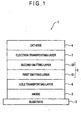
- Fig. 1 shows an organic EL device 1 according to the exemplary embodiment.
- the organic EL device 1 includes a transparent substrate 2, an anode 3, a cathode 4, a hole transporting layer 6, an emitting layer 5 including a first emitting layer 51 and a second emitting layer 52, and an electron transporting layer 7.
- the hole transporting layer 6, the first emitting layer 51, the second emitting layer 52, the electron transporting layer 7 and the cathode 4 are in this sequence layered on the anode 3.
- the first emitting layer 51 is layered between the hole transporting layer 6 and the second emitting layer 52.
- the first emitting layer 51 is adjacent to the hole transporting layer 6 and the second emitting layer 52.
- the first emitting layer 51 contains a first host and a phosphorescent dopant.
- a concentration of the phosphorescent dopant is not particularly limited in the exemplary embodiment but is preferably in a range from 0.1 mass% to 30 mass%, more preferably in a range from 1 mass% to 20 mass%.
- the triplet energy of the first host is 2.8 eV or more and the ionization potential of the first host is 5.5 eV or less.
- the first host is preferably a non-amine-based compound, more preferably a compound represented by the following formula (1).
- R represents a substituent substitutable for a carbazole skeleton or L.
- n represents the number of R. n is 0 to 6, preferably 0 to 4. When n is 2 or larger, a plurality of R may be mutually different.
- each of R 1 to R 6 represents a substituent, examples of which are the same as those mentioned in relation to R in the formula (1).
- L which bonds two carbazole skeletons, is a single bond or a divalent bonding group containing an element such as carbon (C), nitrogen (N), oxygen (O), silicon (Si), phosphorus (P) and sulfur (S).
- These bonding groups may further have a substituent.
- substituent may be the same as those mentioned in relation to R in the formula (1).
- R may be a hydrogen atom.
- hydrogen is meant to also include deuterium.
- the aryl group (aromatic hydrocarbon group) as R may have 6 to 30 carbon atoms forming the aromatic ring (hereinafter referred to as ring carbon atoms).
- the aryl group may have a fused ring structure.
- the alkyl group as R may be substituted with halogen to be a haloalkyl group and the alkoxy group as R may be substituted with halogen to be a haloalkoxy group.
- the heteroaryl group (aromatic heterocyclic group) as R may have 2 to 30 ring carbon atoms.
- the heteroaryl group may have a fused ring structure.
- R 1 and R 2 may be bonded at N-position (9-position) of the carbazole skeleton directly or via a bonding group.
- Examples of the bonding group are X 1 and X 2 in a formula (1A) described below and L 2 and L 3 in a formula (1C) described below.
- an adjacent set of the substituents substituted for the carbazole skeleton may be mutually bonded to form a ring structure.
- the first host is more preferably a compound represented by the following formula (2).
- L bonds carbon atoms provided at 3-positions of two carbazole skeletons.
- R 1 and R 2 may preferably contain no azine ring.
- R 1 to R 6 are as follows:
- the first host is preferably a compound represented by the following formula (1A).
- a 1 represents a substituted or unsubstituted nitrogen-containing heterocyclic group having 1 to 30 ring carbon atoms.
- a 2 represents a substituted or unsubstituted aromatic hydrocarbon group having 6 to 30 ring carbon atoms, or a substituted or unsubstituted nitrogen-containing heterocyclic group having 1 to 30 ring carbon atoms.
- X 1 and X 2 are bonding groups and each independently represent one of the following:
- Y 1 to Y 4 each independently represent one of the following:
- each of p and q is an integer of 1 to 4.
- each of r and s is an integer of 1 to 3.
- a plurality of Y 1 to Y 4 may be mutually the same or different.
- the ring structure is exemplified by structures represented by the following formulae (1B).
- the first host is preferably a compound represented by the following formula (2A).
- a 1 , A 2 , X 1 , X 2 , Y 1 to Y 4 , p, q, r and s are the same as those in the formula (1A).
- each of A 1 and A 2 is preferably a substituted or unsubstituted aromatic heterocyclic group having 2 to 30 ring carbon atoms, or a substituted or unsubstituted fused aromatic heterocyclic group having 2 to 30 ring carbon atoms.
- a 1 is preferably selected from a group consisting of a substituted or unsubstituted pyridine ring, substituted or unsubstituted pyrimidine ring, and substituted or unsubstituted triazine ring, more preferably selected from a substituted or unsubstituted pyrimidine ring, and substituted or unsubstituted triazine ring.
- a 1 in the formula (2A) is preferably a substituted or unsubstituted pyrimidine ring, and the first host is preferably a compound represented by the following formula (2B).
- a 2 , X 1 , Y 1 to Y 4 , p, q, r and s are the same as those in the formula (2A).
- Y 5 represents the same as Y 1 to Y 4 in the formula (2A).
- t is an integer of 1 to 3. When t is an integer of 2 or 3, a plurality of Y 5 may be mutually the same or different.
- a 2 is preferably a nitrogen-containing heterocyclic group.
- a 2 2 is preferably a substituted or unsubstituted aromatic heterocyclic group having 2 to 30 ring carbon atoms, or a substituted or unsubstituted fused aromatic heterocyclic group having 2 to 30 ring carbon atoms.
- a 1 is preferably a substituted or unsubstituted quinazoline ring.
- X 1 is preferably a single bond or a substituted or unsubstituted divalent aromatic hydrocarbon group having 6 to 30 ring carbon atoms.
- X 1 is more preferably a substituted or unsubstituted divalent aromatic hydrocarbon group having 6 to 30 ring carbon atoms.
- X 1 is particularly preferably a phenylene group provided by removing two hydrogen atoms from a benzene ring or a naphthylene group provided by removing two hydrogen atoms from a naphthalene ring.
- X 1 when X 1 is a substituted or unsubstituted benzene ring, A 1 and a carbazolyl group, which are bonded to X 1 , are preferably at meta positions or para positions. Particularly preferably, X 1 is unsubstituted para-phenylene.
- the pyridine ring, pyrimidine ring and triazine ring are more preferably represented by the following formulae (2C).
- each of Y and Y' represents a substituent. Examples of the substituent are the same groups as Y 1 to Y 4 as described above. Y and Y' may be the same or different. Preferred examples thereof are the substituted or unsubstituted aromatic hydrocarbon group or fused aromatic hydrocarbon group having 6 to 30 ring carbon atoms, and the substituted or unsubstituted aromatic heterocyclic group or fused aromatic heterocyclic group having 2 to 30 ring carbon atoms.
- * represents a bonding position to X 1 or X 2 .
- the quinazoline ring is represented by the following formula (2D).
- Y represents a substituent.
- u is an integer of 1 to 5.
- a plurality of Y may be mutually the same or different.
- Examples of the substituent Y in the formula (2D) may be the same as the groups Y 1 to Y 4 described above.
- Preferred examples of the substituent Y are the substituted or unsubstituted aromatic hydrocarbon group or fused aromatic hydrocarbon group having 6 to 30 ring carbon atoms, and the substituted or unsubstituted aromatic heterocyclic group or fused aromatic heterocyclic group having 2 to 30 ring carbon atoms.
- * also represents a bonding position to X 1 or X 2 .
- the alkyl group, alkoxy group, haloalkyl group, haloalkoxy group and alkylsilyl group which are represented by Y 1 to Y 5 , may have a linear, branched or cyclic structure.
- examples of the alkyl group having 1 to 20 carbon atoms are a methyl group, ethyl group, propyl group, isopropyl group, n-butyl group, s-butyl group, isobutyl group, t-butyl group, n-pentyl group, n-hexyl group, n-heptyl group, n-octyl group, n-nonyl group, n-decyl group, n-undecyl group, n-dodecyl group, n-tridecyl group, n-tetradecyl group, n-pentadecyl group, n-hexadecyl group, n-heptadecyl group, n-octadecyl group, neo-pentyl group, 1-methylpentyl group, 2-methylpent
- alkyl group having 1 to 10 carbon atoms examples include a methyl group, ethyl group, propyl group, isopropyl group, n-butyl group, s-butyl group, isobutyl group, t-butyl group, cyclopentyl group, cyclohexyl group and cycloheptyl group.
- alkoxy group having 1 to 20 carbon atoms an alkoxy group having 1 to 6 carbon atoms is preferable and specific examples thereof are a methoxy group, ethoxy group, propoxy group, butoxy group, pentyloxy group, and hexyloxy group.
- the haloalkyl group having 1 to 20 carbon atoms is exemplified by a haloalkyl group provided by substituting the alkyl group having 1 to 20 carbon atoms with one or more halogen atoms.
- Preferred one of the halogen atoms is fluorine.
- the haloalkyl group is exemplified by a trifluoromethyl group and a 2,2,2-trifluoroethyl group.
- the haloalkoxy group having 1 to 20 carbon atoms is exemplified by a haloalkoxy group provided by substituting the alkoxy group having 1 to 20 carbon atoms with one or more halogen atoms.
- examples of the alkylsilyl group having 1 to 10 carbon atoms are a trimethylsilyl group, triethylsilyl group, tributylsilyl group, dimethylethylsilyl group, dimethylisopropylsilyl group, dimethylpropylsilyl group, dimethylbutylsilyl group, dimethyl-tertiary-butylsilyl group and diethylisopropylsilyl group.
- examples of the arylsilyl group having 6 to 30 carbon atoms are a phenyldimethylsilyl group, diphenylmethylsilyl group, diphenyl-tertiary-butylsilyl group and triphenylsilyl group.
- examples of the aromatic heterocyclic group or fused aromatic heterocyclic group having 2 to 30 ring carbon atoms are a pyroryl group, pyrazinyl group, pyridinyl group, indolyl group, isoindolyl group, furyl group, benzofuranyl group, isobenzofuranyl group, dibenzofuranyl group, dibenzothiophenyl group, quinolyl group, isoquinolyl group, quinoxalinyl group, carbazolyl group, phenantridinyl group, acridinyl group, phenanthrolinyl group, thienyl group and a group formed from a pyridine ring, pyrazine ring, pyrimidine ring, pyridazine ring, triazine ring, indol ring, quinoline ring, acridine ring, pirrolidine ring, dio
- examples of the aromatic hydrocarbon group or fused aromatic hydrocarbon group having 6 to 30 ring carbon atoms are a phenyl group, naphthyl group, phenanthryl group, biphenyl group, terphenyl group, quarterphenyl group, fluoranthenyl group, triphenylenyl group, phenanthrenyl group, pyrenyl group, chrysenyl group, fluorenyl group, and 9,9-dimethylfluorenyl group.
- the aromatic hydrocarbon group or fused aromatic hydrocarbon group having 6 to 20 ring carbon atoms is preferable.
- the substituents are preferably a linear, branched or cyclic alkyl group having 1 to 20 carbon atoms; linear, branched or cyclic alkoxy group having 1 to 20 carbon atoms; linear, branched or cyclic haloalkyl group having 1 to 20 carbon atoms; linear, branched or cyclic alkylsilyl group having 1 to 10 carbon atoms; arylsilyl group having 6 to 30 ring carbon atoms; cyano group; halogen atom; aromatic hydrocarbon group or fused aromatic hydrocarbon group having 6 to 30 ring carbon atoms; or aromatic heterocyclic group or fused aromatic heterocyclic group having 2 to 30 ring carbon atoms.
- linear, branched or cyclic alkyl group having 1 to 20 carbon atoms examples include linear, branched or cyclic alkoxy group having 1 to 20 carbon atoms; linear, branched or cyclic haloalkyl group having 1 to 20 carbon atoms; linear, branched or cyclic alkylsilyl group having 1 to 10 carbon atoms; arylsilyl group having 6 to 30 ring carbon atoms; aromatic hydrocarbon group or fused aromatic hydrocarbon group having 6 to 30 ring carbon atoms; and aromatic heterocyclic group or fused aromatic heterocyclic group having 2 to 30 ring carbon atoms are the above-described groups.
- the halogen atom is exemplified by a fluorine atom.
- the first host is preferably a compound represented by the following formula (1C).
- X 1 and X 2 each independently represent an oxygen atom or a sulfur atom, and are not simultaneously sulfur atoms. In other words, X 1 and X 2 are simultaneously oxygen atoms, or, alternatively, one of X 1 and X 2 is an oxygen atom while the other thereof is a sulfur atom.
- R 1 to R 8 each independently represent one of the following:
- a, d, f and h in the formula (1C) each independently represent an integer of 0 to 4.
- b, c, d and g in the formula (1 C) each independently represent an integer of 0 to 3.
- the sum of a to h in the formula (1C) is 6 or less.
- L 1 in the formula (1C) represents one of the following:
- L 2 and L 3 each independently represent one of the following:
- L 1 , L 2 and L 3 in the formula (1C) may be substituted with any one of the above substituents R 1C .
- L 1 is an arylene group having 6 to 18 ring carbon atoms or a heteroarylene group having 5 to 18 ring atoms
- a and b each independently represent an integer of 1 to 4.
- Examples of the alkyl group as R 1 to R 8 in the formula (1C) are a methyl group, ethyl group, propyl group, isopropyl group, n-butyl group, s-butyl group, isobutyl group, t-butyl group, n-pentyl group, n-hexyl group, n-heptyl group, n-octyl group, n-nonyl group, n-decyl group, n-undecyl group, n-dodecyl group, n-tridecyl group, n-tetradecyl group, n-pentadecyl group, n-hexadecyl group, n-heptadecyl group, n-octadecyl group, neo-pentyl group, 1-methylpentyl group, 2-methylpentyl group, 1-pentyl
- Examples of the cycloalkyl group as R 1 to R 8 in the formula (1C) are a cyclopropyl group, cyclobutyl group, cyclopentyl group, cycloheptyl group, norbornyl group and adamantyl group.
- Examples of the alkoxy group as R 1 to R 8 in the formula (1C) are a methoxy group, ethoxy group, propoxy group, butoxy group, pentyloxy group and hexyloxy group, among which ones having 3 or more carbon atoms may have a liner, cyclic or branched structure.
- Examples of the cycloalkoxy group as R 1 to R 8 in the formula (1C) are a cyclopentoxy group and a cyclohexyloxy group.
- Examples of the aryl group as R 1 to R 8 in the formula (1C) are a phenyl group, tolyl group, xylyl group, mesityl group, o-biphenyl group, m-biphenyl group, p-biphenyl group, o-terphenyl group, m-terphenyl group, p-terphenyl, naphthyl group and phenanthryl group.
- a phenyl group and a mesityl group are preferable.
- Examples of the aryloxy group as R 1 to R 8 in the formula (1C) are a phenoxy group and biphenyloxy group.
- heteroaryl group as R 1 to R 8 in the formula (1C) are a carbazolyl group, dibenzofuranyl group, dibenzothiophenyl group, pyrrolyl group, furyl group, thienyl group, silolyl group, pyridyl group, quinolyl group, isoquinolyl group, benzofuryl group, imidazolyl group, pyrimidyl group, selenophenyl group, oxadiazolyl group and triazolyl group.
- the amino group and the silyl group as R 1 to R 8 in the formula (1C) may be substituted with the substituents described above.
- the silyl group is preferably a trimethylsilyl group.
- a, d, f and h in the formula (1C) preferably each independently represent an integer of 0 to 3, more preferably an integer of 0 to 2.
- b, c, d and g in the formula (1C) preferably each independently represent an integer of 0 to 2, more preferably an integer of 0 to 1.
- the sum of a to h in the formula (1C) is preferably 4 or less.
- the divalent bonding group containing N, the divalent bonding group containing O, the divalent bonding group containing Si, the divalent bonding group containing P and the divalent bonding group containing S as L 1 in the formula (1C) are exemplified by bonding groups represented by the following formulae (1D).
- R x , R y and R z each independently represent a hydrogen atom or a group selected from the above substituents R 1C .
- R w is an oxygen atom.
- "-S-" group sulfide group
- phosphoxide group and ether group are preferable.
- the alkylene group having 1 to 20 carbon atoms, the cycloalkylene group having 3 to 20 ring carbon atoms, the arylene group having 6 to 18 ring carbon atoms, the heteroarylene group having 5 to 18 ring atoms, the divalent amino group, or the divalent silyl group as L 1 , L 2 and L 3 in the formula (1 C) may be provided by removing one hydrogen atom in one of the substituents described above in relation to R 1 to R 8 in the formula (1C).
- the arylene group includes a 9,9-fluorenylidene group.
- Examples of the arylene group as L 1 , L 2 and L 3 in the formula (1C) are a 1,4-phenylene group, 1,2-phenylene group, 1,3-phenylene group, 1,4-naphthylene group, 2,6-naphthylene group, 1,5-naphthylene group, 9,10-anthranylene group, 9,10-phenanthrenylene group, 3,6-phenanthrenylene group, 1,6-pyrenylene group, 2,7-pyrenylene group, 6,12-chrysenylene group, 4,4'-biphenylene group, 3,3'-biphenylene group, 2,2'-biphenylene group and 2,7-fluorenylene group.
- a p-phenylene group (1,4-phenylene group), an m-phenylene group (1,3-phenylene group) and a biphenylene group are preferable.
- the heteroarylene group as L 1 , L 2 and L 3 in the formula (1C) are a 2,5-thiophenylene group, 2,5-silolylene group and 2,5-oxadiazolylene group.
- Examples of the amino group as L 1 , L 2 and L 3 in the formula (1C) are an amino group, alkylamino group, arylamino group, aralkylamino group, acylamino group, alkoxycarbonylamino group, aryloxycarbonylamino group and sulfonylamino group. Among the above, a biphenylamino group is preferable.
- Each of the bonding groups represented by L 1 , L 2 and L 3 in the formula (1C) may have a substituent. Examples of such a substituent are the same as those of the substituents R 1C in the formula (1C).
- the first host is preferably a compound represented by the following formula (2E).
- the first host is preferably a compound represented by the following formula (2F). This is because the compound represented by the formula (2F) exhibits a higher chemical stability.
- R 1a , R 4a , R 6a and R 8a in the formula (2F) each independently represent a hydrogen atom or an aryl group having 6 to 18 ring carbon atoms (which is the same as the aryl group described in relation to the substituents R 1C ).
- An arrangement in which each of R 1a , R 4a , R 6a and R 8a is a hydrogen atom corresponds to an arrangement in which each of a, d, h and h in the formula (1F) is 0.
- the aryl group may be further substituted with one of the substituents R 1C .
- each of L 2 and L 3 is preferably a single bond and L 1 is also preferably a single bond. This is because sublimability and an excessive molecular weight may frequently cause thermal decomposition during vapor deposition.
- L 1 to L 3 in the formula (2F) are preferably arranged as follows:
- Each of X 1 and X 2 in the formulae (1C), (2E) and (2F) is preferably an oxygen atom in terms of external quantum efficiency and lifetime.
- the first host is preferably a compound represented by the following formula (2G) among the compounds represented by the above formula (2F).
- R 1a and R 4a in the formula (2G) each independently represent a hydrogen atom or a phenyl group that may be substituted with a methyl group.
- L 1a in the formula (2G) is a single bond or a phenylene group. It should be noted that when both of R 1a and R 4a are hydrogen atoms, L 1a is not a phenylene group.
- the carbazoles When L 1a is a phenylene group while both of R 1a and R 4a are hydrogen atoms in the formula (2G), the carbazoles have the hydrogen atoms at 6-positions thereof and are not bonded to each other at 3-positions thereof via a single bond.
- Such a material should not be a particularly excellent material for forming the first host in terms of chemical stability and carrier balance adjustment.
- the first host is preferably a compound represented by the following formula (9).
- each of R 1 to R 8 is selected from hydrogen, an alkyl group, a cycloalkyl group, an aralkyl group, an alkenyl group, a cycloalkenyl group, an alkynyl group, a hydroxyl group, a mercapto group, an alkoxy group, an alkylthio group, an arylether group, an arylthioether group, an aryl group, a heterocyclic group, halogen, haloalkane, haloalkene, haloalkyne, a cyano group, an aldehyde group, a carbonyl group, a carboxyl group, an ester group, a carbamoyl group, an amino group, a nitro group, a silyl group, a siloxanyl group and a ring structure between adjacent substituents.
- At least one of R 1 to R 4 in the formula (9) is a bonding group Y.
- the bonding group Y in the formula (9) is one of or a combination of two or more of a single bond, alkyl chain, alkylene chain, cycloalkyl chain, aryl chain, amino chain, heterocyclic chain, silyl chain, ether chain and thioether chain.
- R 9 in the formula (9) is selected from hydrogen, an alkyl group and an aryl group.
- n in the formula (9) is a natural number of 2 or more.
- the alkyl group in the formula (9) is a saturated aliphatic hydrocarbon group, such as a methyl group, ethyl group, propyl group and butyl group, which may be substituted or unsubstituted.
- the cycloalkyl group in the formula (9) is a saturated alicyclic hydrocarbon group, such as cyclopropyl, cyclohexyl, norbornyl and adamantyl, which may be substituted or unsubstituted.
- the aralkyl group in the formula (9), which is exemplified by a benzyl group or a phenylethyl group, contains an aromatic hydrocarbon group and an aliphatic hydrocarbon.
- the aliphatic hydrocarbon and the aromatic hydrocarbon may be substituted or unsubstituted.
- the alkenyl group in the formula (9) is an unsaturated aliphatic hydrocarbon group containing a double bond, such as a vinyl group, allyl group and butadienyl group, which may be substituted or unsubstituted.
- the cycloalkenyl group in the formula (9) is an unsaturated alicyclic hydrocarbon group containing a double bond, such as a cyclopentenyl group, cyclopentadienyl group and cyclohexene group, which may be substituted or unsubstituted.
- the alkynyl group in the formula (9) is an unsaturated aliphatic hydrocarbon group containing a triple bond, such as an acetylenyl group, which may be substituted or unsubstituted.
- the alkoxy group in the formula (9), which is exemplified by a methoxy group, contains an aliphatic hydrocarbon group and an ether bond.
- the aliphatic hydrocarbon group may be substituted or unsubstituted.
- the alkylthio group in the formula (9) is formed by substituting an oxygen atom of an ether bond in an alkoxy group with a sulfur atom.
- the arylether group which is exemplified by a phenoxy group, contains an aromatic hydrocarbon group and an ether bond.
- the aromatic hydrocarbon group may be substituted or unsubstituted.
- the arylthioether group in the formula (9) is formed by substituting an oxygen atom of an ether bond in an arylether group with a sulfur atom.
- the aryl group in the formula (9) represents an aromatic hydrocarbon group, such as a phenyl group, naphthyl group, biphenyl group, phenanthryl group, terphenyl group and pyrenyl group, which may be substituted or unsubstituted.
- the heterocyclic group in the formula (9) represents a cyclic structure group containing an atom other than carbon, such as a furyl group, thienyl group, oxazolyl group, pyridyl group, quinolyl group and carbazolyl group, which may be substituted or unsubstituted.
- the halogen in the formula (9) is fluorine, chlorine, bromine or iodine.
- the haloalkane in the formula (9) is provided by substituting a part or the entirety of the above alkyl group with the halogen, an example of which is a trifluoromethyl group.
- the haloalkene in the formula (9) is likewise provided by substituting a part or the entirety of the above alkenyl group with the above halogen.
- the haloalkyne in the formula (9) is likewise provided by substituting a part or the entirety of the above alkynyl with the halogen.
- the other part of each of the alkyl group, alkenyl group and alkynyl may be substituted or unsubstituted.
- Each of the aldehyde group, carbonyl group, ester group, carbamoyl group and amino group in the formula (9) may be substituted with an aliphatic hydrocarbon, alicyclic hydrocarbon, aromatic hydrocarbon, heterocycle or the like.
- the aliphatic hydrocarbon, alicyclic hydrocarbon, aromatic hydrocarbon and heterocycle may be substituted or unsubstituted.
- the silyl group in the formula (9) represents a silicon compound group such as a trimethylsilyl group, which may be substituted or unsubstituted.
- the siloxanyl group in the formula (9), which is exemplified by a trimethylsiloxanyl group contains a silicon compound group and an ether bond.
- the silicon compound group may be substituted or unsubstituted.
- an adjacent set of substituents may form a cyclic structure.
- the formed cyclic structure may be substituted or unsubstituted.
- a compound having a carbazole skeleton represented by the following formula (9A) is preferably usable in the exemplary embodiment because a compound having a dicarbazolyl skeleton has a rigid molecular structure and is excellent in heat resistance.
- Each of R 10 to R 23 in the formula (9A) is selected from the same as those mentioned in relation to R 1 to R 8 in the formula (9).
- Each of R 24 and R 25 in the formula (9A) is selected from hydrogen, an alkyl group and an aryl group. Dicarbazolyl skeletons may be mutually bonded via the substituents of R 24 and R 25 .
- Compounds having a carbazole skeleton represented by the formulae (9) and (9A) are exemplarily structured as follows.
- the first host is also preferably a compound represented by the following formula (10).
- R is hydrogen, an aliphatic alkyl group having 1 to 12 carbon atoms, a branched alkyl group having 1 to 12 carbon atoms, a cyclic alkyl group having 1 to 12 carbon atoms, or an aromatic group having 4 to 14 carbon atoms.
- the aromatic group may be substituted with one or more or two or more alkoxy or amine.
- the first host is preferably a compound represented by the following formula (11).
- each of A 1 to A 7 and A 12 to A 14 is CR 1 .
- each of A 8 to A 11 and A 15 to A 19 is CR 1 or N.
- X is -N(R 4 )-.
- Ar 1 is a substituted or unsubstituted arylene having 6 to 40 carbon atoms, or a substituted or unsubstituted heteroarylene having 3 to 40 carbon atoms.
- a 15 to A 19 are not simultaneously CR 1 when m is equal to 0.
- each of R 1 and R 4 represents any one of the following:
- the first host is preferably a compound represented by the following formula (12).
- R1 to R4 represent the same as R in the formula (1).
- Ar1 and Ar2 represent the aryl group or the heteroaryl group described in relation to R in the formula (1).
- Ar3 and Ar4 represent the aryl group described in relation to R in the formula (1).
- R1 to R6 represent the same as R in the formula (1).
- Ar5 represents the aryl group described in relation to R in the formula (1).
- Ar6 represents a hydrogen atom or the aryl group described in relation to R in the formula (1).
- the first host is preferably a compound represented by the following formula (13).
- R1 to R4 represent the same as R in the formula (1).
- Ar1 and Ar2 represent the aryl group or the heteroaryl group described in relation to R in the formula (1).
- Ar3 and Ar4 represent a hydrogen atom or the aryl group described in relation to R in the formula (1).
- R1 to R6 represent the same as R in the formula (1).
- Ar5 represents the aryl group described in relation to R in the formula (1).
- Ar6 represents a hydrogen atom or the aryl group described in relation to R in the formula (1).
- the phosphorescent dopant contains a metal complex.
- the metal complex preferably has a metal atom selected from Ir (iridium), Pt (platinum), Os (osmium), Au (gold), Cu (copper), Re (rhenium) and Ru (ruthenium), and a ligand.
- the ligand preferably has an ortho-metal bond.
- the phosphorescent material is preferably a compound containing a metal atom selected from Ir, Os and Pt because such a compound, which exhibits high phosphorescence quantum yield, can further enhance external quantum efficiency of an organic EL device.
- the phosphorescent material is more preferably a metal complex such as an iridium complex, osmium complex or platinum complex, among which an iridium complex and platinum complex are more preferable and ortho metalation of an iridium complex is the most preferable. Examples of such a preferable metal complex are shown below.
- At least one of the phosphorescent dopant contained in the emitting layer preferably emits light with a peak emission wavelength in a range of 420 nm to 720 nm.
- the organic EL device can exhibit a high efficiency.
- a preferred peak emission wavelength is in a range of 420 nm to 480 nm.
- the second emitting layer 52 is layered between the first emitting layer 51 and the electron transporting layer 7.
- the second emitting layer 52 is adjacent to the first emitting layer 51 and the electron transporting layer 7
- the second emitting layer 52 contains a second host and a phosphorescent dopant.
- a concentration of the phosphorescent dopant is not particularly limited in the exemplary embodiment but is preferably in a range from 0.1 mass% to 30 mass%, more preferably in a range from 1 mass% to 20 mass%.
- the triplet energy of the second host is 2.8 eV or more.
- the second host is preferably an azine compound.
- the second host is preferably a compound represented by the following formula (3).
- HAR 31 is a substituted or unsubstituted heteroaryl.
- m is an integer of 0 to 5, preferably an integer of 1 to 3, more preferably an integer of 1 or 2.
- n is an integer of 0 to 3. When n is equal to 0, HAR 31 is bonded to a nitrogen atom in the carbazole skeleton.
- each of R 31 and R 32 is a substituted or unsubstituted alkyl group, aryl group or the like. R 31 and R 32 may be bonded to provide a cyclic structure with a fused benzene ring.
- the second host is preferably any one of the compounds represented by the following formulae (4) to (8) and (8A).
- each of Ar 101 to Ar 104 represents one of the following:
- each of R 110 to R 111 represents a substituent, examples of which are the same as those mentioned in relation to R in the formula (1).
- n is an integer of 0 to 4 and m is an integer of 0 to 5.
- each of R 121 to R 128 represents any one of the following:
- the structure in which the skeleton of the formula (8A) is bonded to R 121 to R 128 is a structure in which at least R 121 and R 122 , R 122 and R 123 , R 123 and R 124 , R 125 and R 126 , R 126 and R 127 , or R 127 and R 128 are bonded to the skeleton of the formula (8A).
- R 129 represents any one of the following:
- examples of R 10 are the same as those of R in the formula (1).
- n is the number of R 10 .
- n is an integer of 0 to 4.
- the second host is also preferably the following compound (A-6) or (A-9) having a dibenzofuran skeleton.
- the second host is preferably a compound represented by the following formula (14).
- each of R 1 to R 12 represents a substituent, examples of which are the same as those mentioned in relation to R in the formula (1).
- adjacent ones of R 1 to R 4 , R 5 to R 7 or R 8 to R 12 , or R 7 and R 8 may form a saturated or unsaturated cyclic structure.
- X is an oxygen atom or a sulfur atom.
- the second host is preferably a compound represented by the following formula (15A), (15B) or (15C).
- each of R 1 to R 10 represents a substituent, examples of which are the same as those mentioned in relation to R in the formula (1).
- adjacent ones of R 1 to R 4 , R 5 to R 7 or R 8 to R 10 , or R 7 and R 8 may form a saturated or unsaturated cyclic structure.
- X is an oxygen atom or a sulfur atom.
- the second host is preferably a compound represented by the following formula (16A), (16B) or (16C).
- each of R 1 to R 11 represents a substituent, examples of which are the same as those mentioned in relation to R in the formula (1).
- adjacent ones of R 1 to R 4 , R 5 to R 7 or R 8 to R 11 may form a saturated or unsaturated cyclic structure.
- adjacent ones of R 1 to R 4 , R 5 to R 7 , R 8 to R 9 or R 10 to R 11 , or R 7 and R 8 may form a saturated or unsaturated cyclic structure.
- adjacent ones of R 1 to R 4 , R 5 to R 7 or R 9 to R 11 , or R 7 and R 8 may form a saturated or unsaturated cyclic structure.
- X is an oxygen atom or a sulfur atom.
- the second host is preferably a compound represented by the following formula (17).
- each of R 1 to R 9 represents a substituent, examples of which are the same as those mentioned in relation to R in the formula (1).
- adjacent ones of R 1 to R 4 or R 5 to R 7 may form a saturated or unsaturated cyclic structure.
- X is an oxygen atom or a sulfur atom.
- the second host is preferably a compound represented by the following formula (18) or (19).
- each of R 1 to R 16 is the same as those mentioned in relation to R in the formula (1).
- each of R 1 to R 16 may represent one of the following:
- adjacent ones of R 4 to R 7 or R 8 to R 12 may form a saturated or unsaturated cyclic structure.
- adjacent ones of R 7 to R 11 or R 12 to R 16 may form a saturated or unsaturated cyclic structure.
- X is an oxygen atom or a sulfur atom. When X is an oxygen atom, it is preferable that a fused aromatic hydrocarbon group is not included in the substituent for the dibenzofuran skeleton.
- the second host contains a compound having carbazole rings as a partial structure thereof and having in the molecule a benzene ring or a partial structure represented by the following formula (21), and all the carbazole rings of the compound are each substituted at the 9-position, substituted with a substituent(s) represented by the following formula (20) at one or more of the 1-position to the 8-position, and substituted at the 2-position or the 3-position.
- each of A 1 to A 3 represents a carbon atom, nitrogen atom, oxygen atom or sulfur atom of the aromatic ring represented by Ar1.
- the carbon atom, nitrogen atom, oxygen atom and sulfur atom may have a hydrogen atom or a substituent.
- R 1 represents a substituent.
- Ar1 is a fused ring
- R 1 may be a part of the fused ring.
- X represents an oxygen atom or a sulfur atom.
- each of R 3 , R 4 , R 5 and R 6 represents a hydrogen atom or a substituent.
- Ar represents an aromatic substituent.
- m is an integer of 0 to 4.
- examples of the aromatic ring represented by Ar1 are an aromatic hydrocarbon ring and an aromatic heterocycle.
- examples of the aromatic hydrocarbon ring are a benzene ring, biphenyl ring, naphthalene ring, azulene ring, anthracene ring, phenanthrene ring, pyrene ring, chrysene ring, naphthacene ring, triphenylene ring, o-terphenyl ring, m-terphenyl ring, p-terphenyl ring, acenaphthene ring, coronene ring, fluorene ring, fluoranthrene ring, naphthacene ring, pentacene ring, perylene ring, pentaphene ring, picene ring, pyrene ring, pyranthrene ring and anthraanthrene ring.
- These rings may have a substituent R1.
- substituent R1 are the same as those of R in the formula (1).
- preferable examples of the aromatic hydrocarbon ring represented by Ar1 are a benzene ring and a naphthalene ring.
- aromatic heterocycle examples include a furan ring, benzofuran ring, dibenzofuran ring, thiophene ring, oxazole ring, pyrrole ring, pyridine ring, pyridazine ring, pyrimidine ring, pyrazine ring, triazine ring, benzimidazole ring, oxadiazole ring, triazole ring, imidazole ring, pyrazole ring, thiazole ring, indole ring, benzimidazole ring, benzothiazole ring, benzoxazole ring, quinoxaline ring, quinazoline ring, phthalazine ring, carbazole ring, carboline ring and diazacarbazole ring (i.e., a ring in which one carbon atom in a hydrocarbon ring of a carboline ring is substituted with a nitrogen atom).
- These rings may have a substituent R1.
- substituent R1 are the same as those of R in the formula (1).
- preferable examples of the aromatic heterocycle represented by Ar1 are a benzofuran ring, dibenzofuran ring, pyrrole ring, pyridine ring, imidazole ring and benzimidazole ring.
- the aromatic substituent represented by Ar is an aromatic hydrocarbon ring group (also referred to as an aromatic hydrocarbon group, an aryl group or the like) or an aromatic heterocyclic group.
- the aromatic hydrocarbon ring group are a phenyl group, p-chlorophenyl group, mesityl group, tolyl group, xylyl group, naphthyl group, anthryl group, azulenyl group, acenaphthenyl group, fluorenyl group, phenanthryl group, indenyl group, pyrenyl group and biphenylyl group.
- These aromatic hydrocarbon ring groups may be unsubstituted or may have the substituent represented by R1 in the formula (20).
- aromatic heterocyclic group examples include a pyridyl ring, pyrimidinyl ring, furyl ring, pyrrolyl ring, imidazolyl ring, benzimidazolyl ring, pyrazolyl group, pyrazinyl group, triazolyl ring (e.g., 1,2,4-triazole-1-yl group and 1,2,3-triazole-1-yl group), oxazolyl group, benzoxazolyl group, thiazolyl group, isoxazolyl group, isothiazolyl group, furazanyl group, thienyl group, quinolyl group, benzofuryl group, dibenzofuryl group, benzothienyl group, dibenzothienyl group, indolyl group, carbazolyl group, carbolinyl group, diazacarbazolyl group (i.e., a group in which one carbon atom in a carboline ring of the
- the same phosphorescent dopant described in the explanation of the first emitting layer 51 is usable.
- the phosphorescent dopant of the first emitting layer 51 may be the same as the phosphorescent dopant of the second emitting layer 52 or may be different from the phosphorescent dopant of the second emitting layer 52.
- the triplet energy of the first host and the triplet energy of the second host are 2.8 eV or more and the ionization potential of the first host is 5.5 eV or less.
- an affinity Af 1 of the first host is smaller than an affinity Af 2 of the second host.
- the compounds usable as the first host and the second host are described above, a different compound may be usable as the first host and the second host in the exemplary embodiment as long as the above relationship in energy between the first host and the second host is satisfied.
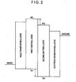
- Fig. 2 shows an energy diagram of the organic EL device 1. Since the ionization potential (Ip 1 ) of the first host is 5.5 eV or less, a gap between the ionization potential (Ip 1 ) and the work function of the anode 3 and a gap between the ionization potential (Ip 1 ) and the ionization potential of the hole transporting layer 6 become small. Thus, holes are easily injected from the hole transporting layer 6 into the first emitting layer 51.
- a disadvantage of this arrangement is that the recombination region of holes and electrons is shifted toward the hole transporting layer 6 and thus electrons flow from the first host, which has small affinity and large band gap, into the hole transporting layer 6, which has a larger affinity than the host, so that the hole transporting layer 6 is likely to be deteriorated because the hole transporting layer 6 does not exhibit electron tolerance.
- the first host has a large triplet energy such as 2.8 eV or more
- holes are easily injected because the ionization potential (Ip 1 ) of the first host is 5.5 eV or less, and thus the recombination region of holes and electrons can be located not near the hole transporting layer 6 but on or near the interface between the first emitting layer 51 and the second emitting layer 52.
- Ip 1 the ionization potential of the first host
- the affinity Af 2 of the second host is larger than the affinity Af 1 of the first host and the triplet energy of the second host is 2.8 eV or more, so that an ionization potential (I P2 ) of the second host is also increased.
- I P2 an ionization potential of the second host
- the affinity Af 1 of the first host becomes small.
- energy barrier i.e., a difference in affinity
- the second host the affinity Af 2 of which is smaller than the affinity Af 1 of the first host, is contained in the second emitting layer 52, so that energy barrier becomes small between the electron transporting layer 7 and the second emitting layer 52 and thus the capability of injecting electrons into the second emitting layer 52 is enhanced.
- the affinity Af 1 of the first host is smaller than the affinity Af 2 of the second host, energy barrier is formed between the second emitting layer 51 and the second emitting layer 52.
- the affinity Af 1 of the first host and the affinity Af 2 of the second host preferably satisfy the following relationship.
- a ⁇ f 2 - A ⁇ f 1 ⁇ 0.4 eV As long as this relationship is satisfied, the capability of injecting electrons into the second emitting layer is enhanced while the capability of injecting electrons into the first emitting layer is lowered, thereby efficiently preventing transfer of electrons toward the hole transporting layer 6 and the anode 3. As a result, the lifetime of the device can be prolonged.
- the electrons can be easily accumulated on or near the interface between the first emitting layer 51 and the second emitting layer 52.
- the electrons and the holes can be efficiently recombined at the region between the first emitting layer 51 and the second emitting layer 52 to improve the luminous efficiency. Since the recombination region is located away from the hole transporting layer 6 and the electron transporting layer 7, less electrons move to the hole transporting layer 6 exhibiting a low electron tolerance and less holes move to the electron transporting layer 7 exhibiting a low hole tolerance.
- the hole transporting layer 6 and the electron transporting layer 7 are less deteriorative. As a result, the lifetime of the organic EL device can be prolonged.
- Ip ionization potential
- a material was irradiated with a light (excitation light) from a deuterium ramp dispersed through a monochromator.
- the resulting ejection of photoelectrons was measured by an electrometer.
- a threshold of the ejection of photoelectrons was calculated by extrapolation.
- the atmospheric ultraviolet photoelectron analyzer AC-3 manufactured by Riken Keiki Co., Ltd. was used.
- the singlet energy (Eg) was obtained by irradiating a toluene-diluted solution of each material with light and converting a maximum wavelength of the resulting absorption spectrum.
- a spectrophotometer manufactured by Hitachi, Ltd., product name: U-3400 was used.
- the triplet energy (EgT) was obtained in the following method.
- the sample set in a quartz cell was cooled down to 77 K and irradiated with an excitation light.
- the resulting phosphorescence was measured relative to a wavelength.
- a tangent line was drawn to be tangent to a rising section of the phosphorescence spectrum on the short-wavelength side, and the obtained wavelength value was converted into an energy value, which was defined as EgT.
- the body of the F-4500 fluorescence spectrophotometer manufactured by Hitachi, Ltd.
- optional accessories for low-temperature measurement were used.
- a cooling device, a low-temperature container, an excitation light source and a light-receiving device may be used in combination for the measurement.
- the following expression was used for conversion of the wavelength.
- the triplet energy refers to a difference between energy in the lowest triplet state and energy in the ground state.
- the singlet energy (often referred to as energy gap) refers to a difference between energy in the lowest singlet state and energy in the ground state.
- the first host preferably has a higher hole mobility for accelerating the transfer of holes to the second host, and the second host preferably has a higher electron mobility for accelerating the transfer of electrons to the first host.
- the hole mobility of the first host is preferably 10 -4 cm 2 /Vs or more at application of an electrical field of 10 4 to 10 6 V/cm.
- the electron mobility of the second host is preferably 10 -5 cm 2 /Vs or more at application of an electrical field of 10 4 to 10 6 V/cm.
- a ratio of the hole mobility of the first host to the electron mobility of the first host is preferably in a range of 1 to 100.
- a ratio of the electron mobility of the second host to the hole mobility of the second host is preferably in a range of 10 to 100.
- a ratio of the hole mobility of the first host to the hole mobility of the second host is preferably in a range of 1 to 1000. Additionally, a difference between a singlet energy and a triplet energy of a host contained in the first host is smaller than a difference between a singlet energy and a triplet energy of a host contained in the second host.
- a method of measuring hole mobility and electron mobility is not specifically limited. Specifically, for instance, a time-of-flight method (i.e., a method according to which the mobility is calculated from a measured transit time of charge in an organic film) and a method according to which the mobility is calculated from the voltage characteristics of a space limited current are usable.
- a time-of-flight method i.e., a method according to which the mobility is calculated from a measured transit time of charge in an organic film
- a method according to which the mobility is calculated from the voltage characteristics of a space limited current are usable.
- an arrangement of electrode / organic layer (an organic material layer forming an electron transporting layer or a hole transporting layer) / electrode is irradiated by a light having a wavelength in an absorption wavelength range of the organic layer to measure the time characteristics of the resulting transient current (transient characteristic time).
- the hole mobility or the electron mobility is calculated by the following expressions.
- the anode 3, the first emitting layer 51, the second emitting layer 52, the cathode 4 and the like are layered on the light-transmissive substrate 2 to provide the organic EL device 1.
- the substrate 2, which supports the anode 3 and the like, is preferably a smoothly-shaped substrate that transmits 50% or more of light in a visible region of 400 nm to 700 nm.
- a glass plate, a polymer plate and the like may be employed.
- the glass plate is formed of soda-lime glass, barium/strontium-containing glass, lead glass, aluminosilicate glass, borosilicate glass, barium borosilicate glass, quartz, or the like.
- the polymer plate is formed of polycarbonate, acryl, polyethylene terephthalate, polyether sulfide, polysulfone or the like.
- the anode 3 of the organic EL device 1 is used for injecting holes into the hole injecting layer, the hole transporting layer 6 or the emitting layer 5. It is effective that the anode 3 has a work function of 4.5 eV or more.
- Exemplary materials for the anode are alloys of indium-tin oxide (ITO), tin oxide (NESA), indium zinc oxide, gold, silver, platinum and copper.
- the anode 3 can be manufactured by forming a thin film from these anode materials on, for instance, the substrate 2 through a method such as vapor deposition or sputtering.
- the anode 3 When light from the emitting layer 5 is to be emitted through the anode 3 as in the exemplary embodiment, the anode 3 preferably transmits more than 10% of the light in the visible region. Sheet resistance of the anode 3 is preferably several hundreds ⁇ / sq. or lower. Although depending on the material of the anode, the film thickness of the anode is typically in a range of 10 nm to 1 ⁇ m, and preferably in a range of 10 nm to 200 nm.
- the cathode 4 may be made by forming a thin film from the above materials on, for instance, the electron transporting layer 7 through a method such as vapor deposition or sputtering.
- light from the emitting layer 5 may be emitted through the cathode 4.
- the cathode 4 preferably transmits more than 10% of the light in the visible region.
- Sheet resistance of the cathode is preferably several hundreds ⁇ /sq. or lower.
- the film thickness of the cathode is typically in a range from 10 nm to 1 ⁇ m, preferably in a range from 50 to 200 nm.
- the organic EL device according to the exemplary embodiment may further include a hole injecting layer, a hole transporting layer, an electron injecting layer and the like as needed in order to increase a current (or luminous) efficiency.
- the organic EL device 1 exemplarily includes the hole transporting layer 6 and the electron transporting layer 7.
- a material for forming these layers is not specifically limited, and any organic material known as a typical organic electroluminescent material is usable. Specifically, an amine derivative, stilbene derivative, silazane derivative, polysilane, aniline copolymer and the like are usable.
- the ionization potential Ip H of an adjacent layer being adjacent to the emitting layer on the anode side of the emitting layer (the hole injecting layer, the hole transporting layer or the like) and the ionization potential Ip 1 of the first emitting layer preferably satisfy a relationship of the following expression.
- the affinity Af E of an adjacent layer being adjacent to the emitting layer on the cathode side of the emitting layer (the electron injecting layer, the electron transporting layer or the like) and the affinity Af 2 of the second emitting layer preferably satisfy a relationship of the following expression. 0 eV ⁇ Af E - Af 2 ⁇ 0.4 eV
- the hole injecting layer or the hole transporting layer preferably contains an aromatic amine compound such as an aromatic amine derivative represented by the following formula (I).
- Ar 1 to Ar 4 each represent one of the following:
- Aromatic amine represented by the following formula (II) can also be preferably used for forming the hole injecting layer or the hole transporting layer.
- Ar 1 to Ar 3 each represent the same as those represented by Ar 1 to Ar 4 of the formula (I).
- the electron injecting layer or the electron transporting layer which aids injection of the electrons into the emitting layer, has a high electron mobility.
- the electron injecting layer is provided for adjusting energy level, by which, for instance, sudden changes of the energy level can be reduced.
- the organic EL device according to the exemplary embodiment of the invention preferably includes the electron injecting layer between the emitting layer and the cathode.
- the electron injecting layer preferably contains a nitrogen-containing cyclic derivative as the main component.
- the electron injecting layer may serve also as the electron transporting layer. It should be noted that "as the main component" means that the nitrogen-containing cyclic derivative is contained in the electron injecting layer at a content of 50 mass% or more.
- a preferable example of an electron transporting material for forming the electron injecting layer is an aromatic heterocyclic compound having at least one heteroatom in the molecule.
- a nitrogen-containing cyclic derivative is preferable.
- the nitrogen-containing cyclic derivative is preferably an aromatic ring having a nitrogen-containing six-membered or five-membered ring skeleton, or a fused aromatic compound having a nitrogen-containing six-membered or five-membered ring skeleton.
- the nitrogen-containing cyclic derivative is preferably exemplified by a nitrogen-containing cyclic metal chelate complex represented by the following formula (A).
- R 2 to R 7 in the formula (A) independently represent one of the following:
- the alkoxycarbonyl group is represented by -COOY'.
- Y' are the same as the examples of the above alkyl group.
- the alkylamino group and the aralkylamino group are represented by -NQ 1 Q 2 .
- Examples of each of Q 1 and Q 2 are the same as the examples described in relation to the above alkyl group and the above aralkyl group (i.e., a group in which a hydrogen atom in the alkyl group is substituted with an aryl group), and preferable examples for each of Q 1 and Q 2 are also the same as those mentioned in relation to the above alkyl group and the above aralkyl group.
- Either one of Q 1 and Q 2 may be a hydrogen atom.
- the aralkyl group is a group in which a hydrogen atom in the alkyl group is substituted with the aryl group.
- the arylamino group is represented by -NAr 1 Ar 2 .
- Examples for each of Ar 1 and Ar 2 are the same as the examples described in relation to the non-fused aromatic hydrocarbon group and the fused aromatic hydrocarbon group.
- Either one of Ar 1 and Ar 2 may be a hydrogen atom.
- M represents aluminum (Al), gallium (Ga) or indium (In), among which In is preferable.
- L in the formula (A) represents a group represented by a formula (A') or (A") below.
- R 8 to R 12 in the formula (A') independently represent a hydrogen atom or a hydrocarbon group having 1 to 40 carbon atoms (which may have a substituent, and an adjacent set of groups may form a cyclic structure.
- R 13 to R 27 in the formula (A") independently represent a hydrogen atom or a hydrocarbon group having 1 to 40 carbon atoms (which may have a substituent), and an adjacent set of groups may form a cyclic structure.
- Examples of the hydrocarbon group having 1 to 40 carbon atoms represented by each of R 8 to R 12 and R 13 to R 27 in the formulae (A') and (A") are the same as those of R 2 to R 7 in the formula (A).
- Examples of a divalent group formed when an adjacent set of R 8 to R 12 and R 13 to R 27 forms a cyclic structure are a tetramethylene group, a pentamethylene group, a hexamethylene group, a diphenylmethane-2,2'-diyl group, a diphenylethane-3,3'-diyl group and a diphenylpropane-4,4'-diyl group.
- the electron transporting layer preferably contains at least one of nitrogen-containing heterocyclic derivatives respectively represented by the following formulae (201) to (203).
- R in the formulae (201) to (203) represents one of the following:
- R 1 in the formulae (201) to (203) represents one of the following:
- R 2 and R 3 in the formulae (201) to (203) independently represent one of the following:
- L in the formulae (201) to (203) represents one of the following:
- Ar 1 in the formulae (201) to (203) represents one of the following:
- Ar 2 in the formulae (201) to (203) represents one of the following:
- Ar 3 in the formulae (201) to (203) represents one of the following:
- 8-hydroxyquinoline or a metal complex of its derivative As an electron transporting compound for the electron injecting layer or the electron transporting layer, 8-hydroxyquinoline or a metal complex of its derivative, an oxadiazole derivative, or a nitrogen-containing heterocyclic derivative is preferable.
- a specific example of the 8-hydroxyquinoline or the metal complex of its derivative is a metal chelate oxinoid compound containing a chelate of oxine (typically 8-quinolinol or 8-hydroxyquinoline).
- oxine typically 8-quinolinol or 8-hydroxyquinoline
- tris(8-quinolinol) aluminum can be used.
- the oxadiazole derivative are as follows.
- each of Ar 17 , Ar 18 , Ar 19 , Ar 21 , Ar 22 and Ar 25 represents a substituted or unsubstituted aromatic or fused aromatic hydrocarbon group having 6 to 40 ring carbon atoms; and Ar 17 and Ar 18 may be mutually the same or different, Ar 19 and Ar 21 may be mutually the same or different, and Ar 22 and Ar 25 may be mutually the same or different.
- the aromatic hydrocarbon group or fused aromatic hydrocarbon group having 6 to 40 ring carbon atoms are a phenyl group, naphthyl group, biphenyl group, anthranil group, perylenyl group and pyrenyl group.
- Examples of the substituent therefor are an alkyl group having 1 to 10 carbon atoms, alkoxy group having 1 to 10 carbon atoms and cyano group.
- Ar 20 , Ar 23 and Ar 24 each represent a substituted or unsubstituted divalent aromatic hydrocarbon group or fused aromatic hydrocarbon group having 6 to 40 ring carbon atoms. Ar 23 and Ar 24 may be mutually the same or different.
- Examples of the divalent aromatic hydrocarbon group or fused aromatic hydrocarbon group are a phenylene group, naphthylene group, biphenylene group, anthranylene group, perylenylene group and pyrenylene group.
- Examples of the substituent therefor are an alkyl group having 1 to 10 carbon atoms, alkoxy group having 1 to 10 carbon atoms and cyano group.
- Such an electron transporting compound is preferably an electron transporting compound that can be favorably formed into a thin film(s).
- Examples of the electron transporting compounds are as follows.
- nitrogen-containing heterocyclic derivative as the electron transporting compound is a nitrogen-containing heterocyclic derivative that is not a metal complex, the derivative being formed of an organic compound represented by either one of the following formulae.
- nitrogen-containing heterocyclic derivative are a five-membered ring or six-membered ring derivative having a skeleton represented by the following formula (B1) and a derivative having a structure represented by the following formula (B2).
- X represents a carbon atom or a nitrogen atom.
- Z 1 and Z 2 each independently represent a group of atoms capable of forming a nitrogen-containing heterocycle.
- the nitrogen-containing heterocyclic derivative is an organic compound having a nitrogen-containing aromatic polycyclic group having a five-membered ring or six-membered ring.
- the nitrogen-containing heterocyclic derivative is preferably a nitrogen-containing aromatic polycyclic organic compound having a skeleton formed by a combination of the skeletons respectively represented by the formulae (B1) and (B2), or by a combination of the skeletons respectively represented by the formulae (B1) and (C).
- a nitrogen-containing group of the nitrogen-containing aromatic polycyclic organic compound is selected from nitrogen-containing heterocyclic groups respectively represented by, for instance, the following formulae.
- R in the formulae represents one of the following:
- a preferable specific compound is a nitrogen-containing heterocyclic derivative represented by the following formula (D).
- HAr - L 1 - Ar 1 - Ar 2 In the formula (D), HAr represents a nitrogen-containing heterocyclic group having 1 to 40 ring carbon atoms (which may have a substituent).
- L 1 represents one of the following:
- Ar 1 represents a divalent aromatic hydrocarbon group having 6 to 40 ring carbon atoms (which may have a substituent).
- Ar 2 represents one of the following:
- L 1 is exemplarily selected from the following group.
- Ar 1 is exemplarily selected from the following arylanthranil groups.
- R 1 to R 14 independently represent one of the following:
- Ar 2 is exemplarily selected from the following group.
- the following compound can be favorably used as the nitrogen-containing aromatic polycyclic organic compound (i.e., the electron transporting compound).
- R 1 to R 4 independently represent one of the following:
- the following compound (see JP-A-2000-173774 ) can also be favorably used as the electron transporting compound.
- R 1 , R 2 , R 3 and R 4 which may be mutually the same or different, each represent an aromatic hydrocarbon group or fused aromatic hydrocarbon group represented by the following formula.
- R 5 , R 6 , R 7 , R 8 and R 9 which may be mutually the same or different, each represent a hydrogen atom, saturated or unsaturated alkoxy group, alkyl group, amino group or alkylamino group. At least one of R 5 , R 6 , R 7 , R 8 and R 9 represents a saturated or unsaturated alkoxy group, alkyl group, amino group or alkylamino group.
- the electron transporting compound may be a polymer compound containing the nitrogen-containing heterocyclic group or nitrogen-containing heterocyclic derivative.
- the thickness of the electron injecting layer or the electron transporting layer is not particularly limited, the thickness is preferably 1 nm to 100 nm.
- the electron injecting layer preferably contains an inorganic compound such as an insulator or a semiconductor in addition to the nitrogen-containing cyclic derivative. Such an insulator or a semiconductor, when contained in the electron injecting layer, can effectively prevent a current leak, thereby enhancing electron injectability of the electron injecting layer.
- the insulator it is preferable to use at least one metal compound selected from the group consisting of an alkali metal chalcogenide, an alkaline earth metal chalcogenide, a halogenide of alkali metal and a halogenide of alkaline earth metal.
- an alkali metal chalcogenide an alkaline earth metal chalcogenide, a halogenide of alkali metal and a halogenide of alkaline earth metal.
- the electron injection capability can further be enhanced.
- preferable examples of the alkali metal chalcogenide are Li 2 O, K 2 O, Na 2 S, Na 2 Se and Na 2 O
- preferable examples of the alkaline earth metal chalcogenide are CaO, BaO, SrO, BeO, BaS and CaSe.
- halogenide of the alkali metal LiF, NaF, KF, LiCl, KCl and NaCl.
- halogenide of the alkaline earth metal are fluorides such as CaF 2 , BaF 2 , SrF 2 , MgF 2 and BeF 2 , and halogenides other than the fluoride.
- Examples of the semiconductor are one of or a combination of two or more of an oxide, a nitride or an oxidized nitride containing at least one element selected from Ba, Ca, Sr, Yb, Al, Ga, In, Li, Na, Cd, Mg, Si, Ta, Sb and Zn.
- the inorganic compound for forming the electron injecting layer is preferably a microcrystalline or amorphous insulator film. When the electron injecting layer is formed of such an insulator film, a more uniform thin film can be formed, thereby reducing pixel defects such as a dark spot.
- Examples of such an inorganic compound are the above-described alkali metal chalcogenide, alkaline earth metal chalcogenide, halogenide of the alkali metal and halogenide of the alkaline earth metal.
- a thickness thereof is preferably in a range of approximately 0.1 nm to 15nm.
- the electron injecting layer according to the present invention may preferably contain the above-described reduction-causing dopant.
- a reduction-causing dopant may be preferably contained in an interfacial region between the cathode and the organic thin-film layer.
- the reduction-causing dopant may be at least one compound selected from an alkali metal, an alkali metal complex, an alkali metal compound, an alkaline earth metal, an alkaline earth metal complex, an alkaline earth metal compound, a rare-earth metal, a rare-earth metal complex, a rare-earth metal compound and the like.
- the alkali metal examples include Na (work function: 2.36 eV), K (work function: 2.28 eV), Rb (work function: 2.16 eV) and Cs (work function: 1.95 eV), and the alkali metal particularly preferably has a work function of 2.9 eV or less.
- the reduction-causing dopant is preferably K, Rb or Cs, more preferably Rb or Cs, the most preferably Cs.
- the alkaline earth metal examples of the alkaline earth metal are Ca (work function: 2.9 eV), Sr (work function: 2.0 eV to 2.5 eV) and Ba (work function: 2.52 eV), among which a substance having a work function of 2.9 eV or less is particularly preferable.
- the rare-earth metal examples include Sc, Y, Ce, Tb and Yb, and the rare-earth metal particularly preferably has a work function of 2.9 eV or less. Since the above preferred metals have particularly high reducibility, addition of a relatively small amount of the metals to an electron injecting zone can enhance luminance intensity and lifetime of the organic EL device.
- alkali metal compound examples include an alkali oxide such as Li 2 O, Cs 2 O or K 2 O and an alkali halogenide such as LiF, NaF, CsF or KF, among which LiF, Li 2 O and NaF are preferable.
- alkaline earth metal compound examples include BaO, SrO, CaO and a mixture thereof, i.e., Ba x Sr 1-x O (0 ⁇ x ⁇ 1), Ba x Ca 1-x O (0 ⁇ x ⁇ 1), among which BaO, SrO and CaO are preferable.
- rare-earth metal compound examples include YbF 3 , ScF 3 , ScO 3 , Y 2 O 3 , Ce 2 O 3 , GdF 3 and TbF 3 , among which YbF 3 , ScF 3 and TbF 3 are preferable.
- the alkali metal complex, the alkaline earth metal complex and the rare-earth metal complex are not specifically limited, as long as at least one of alkali metal ion, alkaline earth metal ion and rare-earth metal ion is contained therein as metal ion.
- Ligand is preferably quinolinol, benzoquinolinol, acridinol, phenanthridinol, hydroxyphenyl oxazole, hydroxyphenyl thiazole, hydroxydiaryl oxadiazole, hydroxydiaryl thiadiazole, hydroxyphenyl pyridine, hydroxyphenyl benzoimidazole, hydroxybenzo triazole, hydroxy fluborane, bipyridyl, phenanthroline, phthalocyanine, porphyrin, cyclopentadiene, ⁇ -diketones, azomethines, or a derivative thereof, but the ligand is not limited thereto.
- the reduction-causing dopant is added to preferably form a layer or an island pattern in the interfacial region.
- the layer of the reduction-causing dopant or the island pattern of the reduction-causing dopant is preferably formed by depositing the reduction-causing dopant by resistance heating deposition while an emitting material for forming the interfacial region or an organic substance as a electron-injecting material are simultaneously deposited, so that the reduction-causing dopant is dispersed in the organic substance.
- Dispersion concentration at which the reduction-causing dopant is dispersed in the organic substance is a mole ratio (organic substance to reduction-causing dopant) of 100:1 to 1:100, preferably 5:1 to 1:5.
- the emitting material or the electron injecting material for forming the organic layer of the interfacial region is initially layered, and the reduction-causing dopant is subsequently deposited singularly thereon by resistance heating deposition to form a preferably 0.1 nm to 15 nm-thick layer.
- the reduction-causing dopant forms the island pattern
- the emitting material or the electron injecting material for forming the organic layer of the interfacial region is initially formed in an island shape, and the reduction-causing dopant is subsequently deposited singularly thereon by resistance heating deposition to form a preferably 0.05 nm to 1 nm-thick island shape.
- a ratio of the main component to the reduction-causing dopant in the organic EL device according to the exemplary embodiment of the invention is preferably a mole ratio (main component to reduction-causing dopant) of 5:1 to 1:5, more preferably 2:1 to 1:2.
- the thickness of each layer between the anode and the cathode is not specifically limited except for the thicknesses particularly specified above.
- the thickness of each layer is typically preferably in a range from several nanometers to 1 ⁇ m because an excessively thinned film is likely to entail defects such as a pin hole while an excessively thickened film requires application of high voltage and deteriorates efficiency.
- a manufacturing method of the organic EL device according to the exemplary embodiment is not particularly limited, and any manufacturing method used for forming a typical organic EL device is usable.
- the respective layers can be formed by vacuum deposition, a casting method, a coating method, a spin coating method or the like.
- the coating method and the spin coating using a solution, in which the organic material of each layer is dispersed, on a transparent polymer such as polycarbonate, polyurethane, polystyrene, polyarylate and polyester the respective layers can be formed by simultaneous deposition of the organic material and the transparent polymer, or the like.
- the invention is not limited to the above description, but may include any modification as long as such modification stays within a scope and a spirit of the invention.
- the organic EL device including the hole transporting layer provided between the anode and the first emitting layer is exemplarily described in the exemplary embodiment, the invention is not limited to such an arrangement.
- the adjacent layer is not limited to the hole transporting layer. According to the invention, such an adjacent layer can be prevented from deterioration resulting from injection of electrons into the adjacent layer, thereby prolonging the lifetime of the organic EL device.
- An adjacent layer such as the electron injecting layer may be provided between the emitting layer and the cathode.
- the organic EL device according to Example 1 was manufactured as follows. A glass substrate (size: 25 mm x 75 mm x 1.1 mm thick, manufactured by Geomatec Co., Ltd.) having an ITO transparent electrode (anode) was ultrasonic-cleaned in isopropyl alcohol for five minutes, and then UV/ozone-cleaned for 30 minutes. After the glass substrate having the transparent electrode line was cleaned, the glass substrate was mounted on a substrate holder of a vacuum deposition apparatus. A compound HT was initially formed onto a surface of the glass substrate where the transparent electrode line was provided so as to cover the transparent electrode. Thus, a 50-nm thick hole transporting layer was formed.
- a compound PBH-01 (the first host) and a compound BD1 (the phosphorescent dopant) were co-deposited on the hole transporting layer. Thus, a 10-nm thick first emitting layer of blue emission was formed. A concentration of the compound BD1 was 10 mass%.
- a compound PBH-04 (the second host) and the compound BD1 (the phosphorescent dopant) were co-deposited on the first emitting layer. Thus, a 40-nm thick second emitting layer of blue emission was formed. A concentration of the compound BD1 was 10 mass%.
- the compound PBH-04 was layered on the second emitting layer to form a 5-nm thick exciton blocking layer. The exciton blocking layer is adapted to prevent diffusion of the triplet energy from the second emitting layer.
- a compound ET was layered on the exciton blocking layer to form a 30-nm thick electron transporting layer.
- Lithium fluoride (LiF) was vapor-deposited at a rate of 1 ⁇ /min to form a 1-nm thick electron-injecting cathode.
- Metallic aluminum (Al) was vapor-deposited on the electron-injecting cathode to form an 80-nm thick cathode.
- the organic EL devices according respectively to Examples 2 to 4 and Comparatives 1 to 5 were formed in the same manner as in Example 1 except that the materials, a thickness of each of the layers and a concentration of each of the emitting materials were changed as shown in Table 1.
- the numerals in parentheses in Table 1 indicate a thickness of each layer (unit: nm).
- the percentages in parentheses in Table 1 indicate a ratio of the phosphorescent material in each emitting layer (mass percentage).
- Example 1 ITO / HT(50) / PBH-01: BD1 (10, 10%) / PBH-4: BD1 (40, 10%) / PBH-4(5) / ET(30) / LiF(1) / Al(80)
- Example 2 ITO / HT(50) / PBH-01: BD1 (10, 10%) / PBH-5: BD1 (40, 10%) / PBH-5(5) ET(30) / LiF(1) / Al(80)
- Example 3 ITO / HT(50) / PBH-02: BD1 (10, 10%) / PBH-4: BD1 (40, 10%) / PBH-4(5) / ET(30) / LiF(1) / Al(80)
- Example 4 ITO / HT(50) / PBH-03: BD1 (10, 10%) / PBH-4: BD1 (40, 10%) / PBH-4(5) / ET(30) / LiF(1) / Al(80) Comparative
- BD1 (10, 10%) / Host No. 2: BD1 (40, 10%) / ET(30) / LiF(1) / Al(80) Comparative 5 ITO / HT(50) / Host No. 3: BD1 (10. 10%) / Host No. 4: BD1 (40, 10%) / ET(30) / LiF(1) / Al(80)
- Each of the organic EL devices according to Examples 1 to 4 and Comparatives 1 to 5 was driven at a current density of 10 mA/cm 2 , and then voltage, luminous efficiency and durability (lifetime) were measured and evaluated. The results are shown in Table 5. A period of time elapsed until the initial luminescence intensity decreased to half was defined as the lifetime.
- each of the organic EL devices according to Examples 1 to 4 exhibits an excellent luminous efficiency and has a longer lifetime while requiring a lower driving voltage.
- each of the organic EL devices according to Comparatives 1, 2, 4 and 5 exhibited a lower luminous efficiency and had a particularly shorter lifetime while requiring a higher driving voltage. It was found out that the organic EL device according to Comparative 3 exhibited a lower luminous efficiency and had a particularly shorter lifetime.
- the first host of the first emitting layer of the organic EL device according to Comparative 3 had an ionization potential of 5.5 eV for efficient injection of holes into the first emitting layer, the first emitting layer and the second emitting layer thereof had the same value of affinity and thus the recombination region of holes and electrons coincided with the interfacial region between the electron transporting layer and the second emitting layer, so that the compound of the electron transporting layer was deteriorated due to a low hole tolerance thereof.
- An organic EL device according to the invention is usable as a highly efficient and long-life organic EL device capable of blue emission.
Landscapes
- Engineering & Computer Science (AREA)
- Physics & Mathematics (AREA)
- Chemical & Material Sciences (AREA)
- Optics & Photonics (AREA)
- Materials Engineering (AREA)
- Manufacturing & Machinery (AREA)
- Spectroscopy & Molecular Physics (AREA)
- Organic Chemistry (AREA)
- Electroluminescent Light Sources (AREA)
Applications Claiming Priority (2)
| Application Number | Priority Date | Filing Date | Title |
|---|---|---|---|
| JP2010131538A JP2013200939A (ja) | 2010-06-08 | 2010-06-08 | 有機エレクトロルミネッセンス素子 |
| PCT/JP2011/063103 WO2011155508A1 (ja) | 2010-06-08 | 2011-06-08 | 有機エレクトロルミネッセンス素子 |
Publications (2)
| Publication Number | Publication Date |
|---|---|
| EP2582206A1 true EP2582206A1 (de) | 2013-04-17 |
| EP2582206A4 EP2582206A4 (de) | 2014-01-15 |
Family
ID=45098112
Family Applications (1)
| Application Number | Title | Priority Date | Filing Date |
|---|---|---|---|
| EP11792465.4A Withdrawn EP2582206A4 (de) | 2010-06-08 | 2011-06-08 | Organisches elektrolumineszenzelement |
Country Status (4)
| Country | Link |
|---|---|
| US (1) | US20130092913A1 (de) |
| EP (1) | EP2582206A4 (de) |
| JP (1) | JP2013200939A (de) |
| WO (1) | WO2011155508A1 (de) |
Cited By (4)
| Publication number | Priority date | Publication date | Assignee | Title |
|---|---|---|---|---|
| US8981393B2 (en) | 2012-04-20 | 2015-03-17 | Semiconductor Energy Laboratory Co., Ltd. | Light-emitting element, light-emitting device, display device, electronic device, and lighting device |
| US9142710B2 (en) | 2012-08-10 | 2015-09-22 | Semiconductor Energy Laboratory Co., Ltd. | Light-emitting element, light-emitting device, display device, electronic device, and lighting device |
| EP3306695A4 (de) * | 2015-05-26 | 2019-01-09 | Boe Technology Group Co. Ltd. | Doppellagige dotierte phosphoreszierende lichtemittierende vorrichtung und herstellungsverfahren dafür |
| US11276834B2 (en) | 2015-12-25 | 2022-03-15 | Sony Corporation | Light emitting element and display device |
Families Citing this family (32)
| Publication number | Priority date | Publication date | Assignee | Title |
|---|---|---|---|---|
| KR20110122051A (ko) | 2010-05-03 | 2011-11-09 | 제일모직주식회사 | 유기광전소자용 화합물 및 이를 포함하는 유기광전소자 |
| KR101478000B1 (ko) * | 2010-12-21 | 2015-01-05 | 롬엔드하스전자재료코리아유한회사 | 신규한 유기 발광 화합물 및 이를 채용하고 있는 유기 전계 발광 소자 |
| TWI538977B (zh) | 2011-02-07 | 2016-06-21 | Idemitsu Kosan Co | A double carbazole derivative and an organic electroluminescent element using the same |
| WO2012108389A1 (ja) | 2011-02-07 | 2012-08-16 | 出光興産株式会社 | ビスカルバゾール誘導体及びそれを用いた有機エレクトロルミネッセンス素子 |
| CN103429570A (zh) * | 2011-03-24 | 2013-12-04 | 出光兴产株式会社 | 双咔唑衍生物及使用其的有机电致发光元件 |
| CN107501244B (zh) | 2011-11-22 | 2022-05-03 | 出光兴产株式会社 | 芳香族杂环衍生物、有机电致发光元件用材料以及有机电致发光元件 |
| EP2790239B1 (de) | 2011-12-05 | 2020-02-05 | Idemitsu Kosan Co., Ltd | Material für ein organisches elektrolumineszenzelement und organisches elektrolumineszenzelement |
| JP6060095B2 (ja) | 2012-02-03 | 2017-01-11 | 出光興産株式会社 | カルバゾール化合物、有機エレクトロルミネッセンス素子用材料および有機エレクトロルミネッセンス素子 |
| US9299942B2 (en) * | 2012-03-30 | 2016-03-29 | Semiconductor Energy Laboratory Co., Ltd. | Light-emitting element, light-emitting device, display device, electronic appliance, and lighting device |
| JP6159037B2 (ja) * | 2012-04-20 | 2017-07-05 | 株式会社半導体エネルギー研究所 | 発光素子、照明装置、発光装置、表示装置、電子機器 |
| WO2013172835A1 (en) * | 2012-05-17 | 2013-11-21 | Universal Display Corporation | Biscarbazole derivative host materials for oled emissive region |
| US9966541B2 (en) * | 2012-06-14 | 2018-05-08 | Idemitsu Kosan Co. Ltd. | Biscarbazole derivative host materials and green emitter for OLED emissive region |
| WO2013187894A1 (en) * | 2012-06-14 | 2013-12-19 | Universal Display Corporation | Biscarbazole derivative host materials and red emitter for oled emissive region |
| JP6088995B2 (ja) | 2013-10-24 | 2017-03-01 | 出光興産株式会社 | 有機エレクトロルミネッセンス素子および電子機器 |
| KR102523989B1 (ko) | 2013-12-02 | 2023-04-21 | 가부시키가이샤 한도오따이 에네루기 켄큐쇼 | 발광 소자, 발광 장치, 전자 기기, 및 조명 장치 |
| KR102308903B1 (ko) * | 2014-06-17 | 2021-10-06 | 삼성디스플레이 주식회사 | 유기 발광 소자 |
| JP5880679B2 (ja) * | 2014-07-16 | 2016-03-09 | 住友化学株式会社 | 発光素子の製造方法 |
| KR102241847B1 (ko) * | 2014-07-29 | 2021-04-20 | 삼성디스플레이 주식회사 | 유기 발광 소자 |
| WO2016129694A1 (ja) * | 2015-02-13 | 2016-08-18 | 出光興産株式会社 | 化合物、有機エレクトロルミネッセンス素子用材料、インク組成物、有機エレクトロルミネッセンス素子、及び電子機器 |
| KR102424977B1 (ko) | 2015-04-14 | 2022-07-26 | 삼성디스플레이 주식회사 | 축합환 화합물 및 이를 포함한 유기 발광 소자 |
| KR102630644B1 (ko) | 2015-12-17 | 2024-01-30 | 삼성디스플레이 주식회사 | 유기 발광 소자 |
| CN105895819B (zh) * | 2016-04-28 | 2018-07-06 | 京东方科技集团股份有限公司 | 一种oled器件及其制备方法、oled显示面板 |
| WO2021161527A1 (ja) * | 2020-02-14 | 2021-08-19 | シャープ株式会社 | 表示装置 |
| WO2022114156A1 (ja) * | 2020-11-26 | 2022-06-02 | 出光興産株式会社 | 有機エレクトロルミネッセンス素子、有機エレクトロルミネッセンス発光装置及び電子機器 |
| KR102891037B1 (ko) * | 2020-12-18 | 2025-11-25 | 삼성디스플레이 주식회사 | 발광 소자 및 이를 포함하는 장치 |
| WO2022191234A1 (ja) * | 2021-03-11 | 2022-09-15 | 出光興産株式会社 | 有機エレクトロルミネッセンス素子、電子機器及び有機エレクトロルミネッセンス素子の製造方法 |
| JP2024084865A (ja) * | 2021-03-12 | 2024-06-26 | 出光興産株式会社 | 有機エレクトロルミネッセンス素子の製造方法、有機エレクトロルミネッセンス素子パネル及び電子機器 |
| JP2024094442A (ja) * | 2021-03-12 | 2024-07-10 | 出光興産株式会社 | 有機エレクトロルミネッセンス素子及び電子機器 |
| JP2024112326A (ja) * | 2021-04-26 | 2024-08-21 | 出光興産株式会社 | 有機エレクトロルミネッセンス素子、有機エレクトロルミネッセンス表示装置及び電子機器 |
| JP2024112327A (ja) * | 2021-04-26 | 2024-08-21 | 出光興産株式会社 | 有機エレクトロルミネッセンス素子、有機エレクトロルミネッセンス表示装置及び電子機器 |
| JP2024128989A (ja) * | 2021-06-04 | 2024-09-26 | 出光興産株式会社 | 有機エレクトロルミネッセンス素子及び電子機器 |
| JP2025131943A (ja) * | 2022-06-07 | 2025-09-10 | 出光興産株式会社 | 有機エレクトロルミネッセンス素子及び電子機器 |
Family Cites Families (28)
| Publication number | Priority date | Publication date | Assignee | Title |
|---|---|---|---|---|
| JP3704748B2 (ja) | 1995-06-23 | 2005-10-12 | 東洋インキ製造株式会社 | 有機エレクトロルミネッセンス素子用電子輸送材料およびそれを用いた有機エレクトロルミネッセンス素子 |
| JP2000173774A (ja) | 1998-12-09 | 2000-06-23 | Sony Corp | 有機電界発光素子 |
| JP4382961B2 (ja) | 2000-05-02 | 2009-12-16 | 富士フイルム株式会社 | 発光素子 |
| JP2002184581A (ja) * | 2000-12-13 | 2002-06-28 | Sanyo Electric Co Ltd | 有機発光素子 |
| JP2004319456A (ja) * | 2003-03-31 | 2004-11-11 | Sanyo Electric Co Ltd | 有機エレクトロルミネッセンス素子 |
| US7374828B2 (en) * | 2003-12-05 | 2008-05-20 | Eastman Kodak Company | Organic electroluminescent devices with additive |
| TW200541401A (en) * | 2004-02-13 | 2005-12-16 | Idemitsu Kosan Co | Organic electroluminescent device |
| DE102004057072A1 (de) | 2004-11-25 | 2006-06-01 | Basf Ag | Verwendung von Übergangsmetall-Carbenkomplexen in organischen Licht-emittierenden Dioden (OLEDs) |
| JP4794919B2 (ja) * | 2005-06-20 | 2011-10-19 | 富士フイルム株式会社 | 有機電界発光素子 |
| US8021763B2 (en) * | 2005-11-23 | 2011-09-20 | The Trustees Of Princeton University | Phosphorescent OLED with interlayer |
| JP5228281B2 (ja) * | 2006-03-20 | 2013-07-03 | コニカミノルタ株式会社 | 有機エレクトロルミネッセンス素子、有機エレクトロルミネッセンス素子を用いた表示装置及び照明装置 |
| JP5055818B2 (ja) * | 2006-04-19 | 2012-10-24 | コニカミノルタホールディングス株式会社 | 有機エレクトロルミネッセンス素子材料、有機エレクトロルミネッセンス素子、表示装置及び照明装置 |
| JP5233081B2 (ja) * | 2006-05-17 | 2013-07-10 | コニカミノルタ株式会社 | 有機エレクトロルミネッセンス素子材料、有機エレクトロルミネッセンス素子、表示装置及び照明装置 |
| WO2008035571A1 (en) * | 2006-09-20 | 2008-03-27 | Konica Minolta Holdings, Inc. | Organic electroluminescence element |
| JP2010504634A (ja) | 2006-09-21 | 2010-02-12 | ビーエーエスエフ ソシエタス・ヨーロピア | 長寿命oledディスプレイ |
| JP5011908B2 (ja) | 2006-09-26 | 2012-08-29 | コニカミノルタホールディングス株式会社 | 有機エレクトロルミネッセンス素子、表示装置および照明装置 |
| JP2008135498A (ja) * | 2006-11-28 | 2008-06-12 | Toray Ind Inc | 発光素子 |
| US20080286610A1 (en) * | 2007-05-17 | 2008-11-20 | Deaton Joseph C | Hybrid oled with fluorescent and phosphorescent layers |
| US20090001875A1 (en) * | 2007-06-29 | 2009-01-01 | Yun Chi | Organic light-emitting device incorporating multifunctional osmium complexes |
| KR101577465B1 (ko) | 2007-07-05 | 2015-12-14 | 바스프 에스이 | 카르벤 전이 금속 착체 이미터, 및 디실릴카르바졸, 디실릴디벤조푸란, 디실릴디벤조티오펜, 디실릴디벤조포스폴, 디실릴디벤조티오펜 s-옥사이드 및 디실릴디벤조티오펜 s,s-디옥사이드로부터 선택된 1종 이상의 화합물을 포함하는 유기 발광 다이오드 |
| KR101612135B1 (ko) | 2007-10-17 | 2016-04-12 | 바스프 에스이 | 가교된 카르벤 리간드를 갖는 전이 금속 착체 및 oled에 있어서의 이의 용도 |
| EP2221897A4 (de) * | 2007-11-22 | 2012-08-08 | Idemitsu Kosan Co | Organisches el-element und ein organisches el-material enthaltende lösung |
| WO2009085344A2 (en) | 2007-12-28 | 2009-07-09 | Universal Display Corporation | Dibenzothiophene-containing materials in phosphorescent light emitting diodes |
| JP2009211892A (ja) * | 2008-03-03 | 2009-09-17 | Fujifilm Corp | 有機電界発光素子 |
| JP2010034484A (ja) | 2008-07-01 | 2010-02-12 | Nippon Hoso Kyokai <Nhk> | 有機エレクトロルミネッセンス素子 |
| JP2010161357A (ja) * | 2008-12-10 | 2010-07-22 | Fujifilm Corp | 有機電界発光素子及び発光装置 |
| JP5697856B2 (ja) * | 2009-06-24 | 2015-04-08 | コニカミノルタ株式会社 | 有機エレクトロルミネッセンス素子、白色有機エレクトロルミネッセンス素子、表示装置及び照明装置 |
| JP5124785B2 (ja) * | 2009-12-07 | 2013-01-23 | 新日鉄住金化学株式会社 | 有機発光材料及び有機発光素子 |
-
2010
- 2010-06-08 JP JP2010131538A patent/JP2013200939A/ja active Pending
-
2011
- 2011-06-08 EP EP11792465.4A patent/EP2582206A4/de not_active Withdrawn
- 2011-06-08 WO PCT/JP2011/063103 patent/WO2011155508A1/ja not_active Ceased
- 2011-06-08 US US13/702,600 patent/US20130092913A1/en not_active Abandoned
Cited By (18)
| Publication number | Priority date | Publication date | Assignee | Title |
|---|---|---|---|---|
| US10505135B2 (en) | 2012-04-20 | 2019-12-10 | Semiconductor Energy Laboratory Co., Ltd. | Light-emitting element, light-emitting device, display device, electronic device, and lighting device |
| US10797257B2 (en) | 2012-04-20 | 2020-10-06 | Semiconductor Energy Laboratory Co., Ltd. | Light-emitting element, light-emitting device, display device, electronic device, and lighting device |
| US9263695B2 (en) | 2012-04-20 | 2016-02-16 | Semiconductor Energy Laboratory Co., Ltd. | Light-emitting element, light-emitting device, display device, electronic device, and lighting device |
| US12127419B2 (en) | 2012-04-20 | 2024-10-22 | Semiconductor Energy Laboratory Co., Ltd. | Light-emitting element, light-emitting device, display device, electronic device, and lighting device |
| US9680120B2 (en) | 2012-04-20 | 2017-06-13 | Semiconductor Energy Laboratory Co., Ltd. | Light-emitting element, light-emitting device, display device, electronic device, and lighting device |
| US8981393B2 (en) | 2012-04-20 | 2015-03-17 | Semiconductor Energy Laboratory Co., Ltd. | Light-emitting element, light-emitting device, display device, electronic device, and lighting device |
| US10164206B2 (en) | 2012-04-20 | 2018-12-25 | Semiconductor Energy Laboratory Co., Ltd. | Light-emitting element, light-emitting device, display device, electronic device, and lighting device |
| US11778846B2 (en) | 2012-04-20 | 2023-10-03 | Semiconductor Energy Laboratory Co., Ltd. | Light-emitting element, light-emitting device, display device, electronic device, and lighting device |
| US11177451B2 (en) | 2012-04-20 | 2021-11-16 | Semiconductor Energy Laboratory Co., Ltd. | Light-emitting element, light-emitting device, display device, electronic device, and lighting device |
| US10121984B2 (en) | 2012-08-10 | 2018-11-06 | Semiconductor Energy Laboratory Co., Ltd. | Light-emitting element, light-emitting device, display device, electronic device, and lighting device |
| US10665808B2 (en) | 2012-08-10 | 2020-05-26 | Semiconductor Energy Laboratory Co., Ltd. | Light-emitting element, light-emitting device, display device, electronic device, and lighting device |
| US11018313B2 (en) | 2012-08-10 | 2021-05-25 | Semiconductor Energy Laboratory Co., Ltd. | Light-emitting element, light-emitting device, display device, electronic device, and lighting device |
| US9142710B2 (en) | 2012-08-10 | 2015-09-22 | Semiconductor Energy Laboratory Co., Ltd. | Light-emitting element, light-emitting device, display device, electronic device, and lighting device |
| US11690239B2 (en) | 2012-08-10 | 2023-06-27 | Semiconductor Energy Laboratory Co., Ltd. | Light-emitting element, light-emitting device, display device, electronic device, and lighting device |
| US12029059B2 (en) | 2012-08-10 | 2024-07-02 | Semiconductor Energy Laboratory Co., Ltd. | Light-emitting element, light-emitting device, display device, electronic device, and lighting device |
| US9559324B2 (en) | 2012-08-10 | 2017-01-31 | Semiconductor Energy Laboratory Co., Ltd. | Light-emitting element, light-emitting device, display device, electronic device, and lighting device |
| EP3306695A4 (de) * | 2015-05-26 | 2019-01-09 | Boe Technology Group Co. Ltd. | Doppellagige dotierte phosphoreszierende lichtemittierende vorrichtung und herstellungsverfahren dafür |
| US11276834B2 (en) | 2015-12-25 | 2022-03-15 | Sony Corporation | Light emitting element and display device |
Also Published As
| Publication number | Publication date |
|---|---|
| JP2013200939A (ja) | 2013-10-03 |
| WO2011155508A1 (ja) | 2011-12-15 |
| EP2582206A4 (de) | 2014-01-15 |
| US20130092913A1 (en) | 2013-04-18 |
Similar Documents
| Publication | Publication Date | Title |
|---|---|---|
| EP2582206A1 (de) | Organisches elektrolumineszenzelement | |
| EP2581957A1 (de) | Organisches elektrolumineszenzelement | |
| EP2674429B1 (de) | Biscarbazolderivat und organisches elektrolumineszenzelement das dieses verwendet | |
| EP3269720B1 (de) | Neuartige verbindung, organisches elektrolumineszentes element und elektronische vorrichtung | |
| JP6195828B2 (ja) | 有機エレクトロルミネッセンス素子用材料、及びそれを用いた有機エレクトロルミネッセンス素子 | |
| EP3584850A1 (de) | Organisches elektrolumineszenzelement und elektronische vorrichtung | |
| JP5756288B2 (ja) | 縮合多環化合物、有機エレクトロルミネッセンス素子用材料、及びそれを用いた有機エレクトロルミネッセンス素子 | |
| EP2738166A1 (de) | Aromatisches heterozyklisches stickstoffderivat und organisches elektrolumineszenzelement damit | |
| KR102282551B1 (ko) | 카바졸 유도체, 이것을 이용한 유기 전기발광 소자용 재료, 및 이것을 이용한 유기 전기발광 소자 및 전자 기기 | |
| EP3010055A1 (de) | Material für organische elektrolumineszierende elemente, organisches elektrolumineszierendes element damit und elektronische vorrichtung | |
| EP2489664A1 (de) | Fluorenhaltige aromatische verbindung, material für ein organisches elektrolumineszierendes element und organisches elektrolumineszierendes element damit | |
| EP2383816A1 (de) | Organisches elektrolumineszenzelement | |
| KR20180095916A (ko) | 헤테로 축합된 페닐퀴나졸린 및 전자 소자에서의 그의 용도 | |
| KR20190083000A (ko) | 유기 일렉트로 루미네센스 소자 및 전자 기기 | |
| JPWO2011125680A1 (ja) | 有機エレクトロルミネッセンス素子用材料及びそれを用いた有機エレクトロルミネッセンス素子 | |
| EP3040335B1 (de) | Verbindung, organisches elektrolumineszierendes element und elektronische vorrichtung | |
| KR101996512B1 (ko) | 화합물 및 이를 포함하는 유기 전자 소자 | |
| CN113015734A (zh) | 杂环化合物及包含其的有机发光器件 | |
| US12584067B2 (en) | Compound, material for organic electroluminescent element, organic electroluminescent element, and electronic equipment | |
| WO2014051004A1 (ja) | 有機エレクトロルミネッセンス素子用材料及び有機エレクトロルミネッセンス素子 | |
| JP2012140367A (ja) | 縮合多環化合物、有機エレクトロルミネッセンス素子用材料、及びそれを用いた有機エレクトロルミネッセンス素子 | |
| WO2014054263A1 (ja) | 有機エレクトロルミネッセンス素子用材料、及びそれを用いた有機エレクトロルミネッセンス素子 | |
| US12289995B2 (en) | Compound, material for organic electroluminescent element, organic electroluminescent element and electronic device | |
| EP2963032A1 (de) | Neuartiges naphthotriazolderivat und organisches elektrolumineszenzelement | |
| EP3269789B1 (de) | Lichtemittierendes material und organisches elektrolumineszentes element |
Legal Events
| Date | Code | Title | Description |
|---|---|---|---|
| PUAI | Public reference made under article 153(3) epc to a published international application that has entered the european phase |
Free format text: ORIGINAL CODE: 0009012 |
|
| 17P | Request for examination filed |
Effective date: 20121214 |
|
| AK | Designated contracting states |
Kind code of ref document: A1 Designated state(s): AL AT BE BG CH CY CZ DE DK EE ES FI FR GB GR HR HU IE IS IT LI LT LU LV MC MK MT NL NO PL PT RO RS SE SI SK SM TR |
|
| RIN1 | Information on inventor provided before grant (corrected) |
Inventor name: NUMATA, MASAKI Inventor name: NISHIMURA, KAZUKI Inventor name: KUMA, HITOSHI Inventor name: HOSOKAWA, CHISHIO Inventor name: NAGASHIMA, HIDEAKI |
|
| DAX | Request for extension of the european patent (deleted) | ||
| A4 | Supplementary search report drawn up and despatched |
Effective date: 20131216 |
|
| RIC1 | Information provided on ipc code assigned before grant |
Ipc: H01L 51/50 20060101ALI20131210BHEP Ipc: H05B 33/12 20060101AFI20131210BHEP |
|
| STAA | Information on the status of an ep patent application or granted ep patent |
Free format text: STATUS: THE APPLICATION IS DEEMED TO BE WITHDRAWN |
|
| 18D | Application deemed to be withdrawn |
Effective date: 20140722 |