EP2582586B1 - Boîte de stockage avec couvercle et poignée - Google Patents
Boîte de stockage avec couvercle et poignée Download PDFInfo
- Publication number
- EP2582586B1 EP2582586B1 EP11743422.5A EP11743422A EP2582586B1 EP 2582586 B1 EP2582586 B1 EP 2582586B1 EP 11743422 A EP11743422 A EP 11743422A EP 2582586 B1 EP2582586 B1 EP 2582586B1
- Authority
- EP
- European Patent Office
- Prior art keywords
- box
- lid
- vertical
- horizontal
- storage device
- Prior art date
- Legal status (The legal status is an assumption and is not a legal conclusion. Google has not performed a legal analysis and makes no representation as to the accuracy of the status listed.)
- Active
Links
Images


Classifications
-
- B—PERFORMING OPERATIONS; TRANSPORTING
- B65—CONVEYING; PACKING; STORING; HANDLING THIN OR FILAMENTARY MATERIAL
- B65D—CONTAINERS FOR STORAGE OR TRANSPORT OF ARTICLES OR MATERIALS, e.g. BAGS, BARRELS, BOTTLES, BOXES, CANS, CARTONS, CRATES, DRUMS, JARS, TANKS, HOPPERS, FORWARDING CONTAINERS; ACCESSORIES, CLOSURES, OR FITTINGS THEREFOR; PACKAGING ELEMENTS; PACKAGES
- B65D43/00—Lids or covers for rigid or semi-rigid containers
- B65D43/26—Mechanisms for opening or closing, e.g. pedal-operated
-
- A—HUMAN NECESSITIES
- A45—HAND OR TRAVELLING ARTICLES
- A45C—PURSES; LUGGAGE; HAND CARRIED BAGS
- A45C13/00—Details; Accessories
- A45C13/26—Special adaptations of handles
- A45C13/28—Combinations of handles with other devices
-
- B—PERFORMING OPERATIONS; TRANSPORTING
- B25—HAND TOOLS; PORTABLE POWER-DRIVEN TOOLS; MANIPULATORS
- B25H—WORKSHOP EQUIPMENT, e.g. FOR MARKING-OUT WORK; STORAGE MEANS FOR WORKSHOPS
- B25H3/00—Storage means or arrangements for workshops facilitating access to, or handling of, work tools or instruments
- B25H3/02—Boxes
-
- B—PERFORMING OPERATIONS; TRANSPORTING
- B65—CONVEYING; PACKING; STORING; HANDLING THIN OR FILAMENTARY MATERIAL
- B65D—CONTAINERS FOR STORAGE OR TRANSPORT OF ARTICLES OR MATERIALS, e.g. BAGS, BARRELS, BOTTLES, BOXES, CANS, CARTONS, CRATES, DRUMS, JARS, TANKS, HOPPERS, FORWARDING CONTAINERS; ACCESSORIES, CLOSURES, OR FITTINGS THEREFOR; PACKAGING ELEMENTS; PACKAGES
- B65D25/00—Details of other kinds or types of rigid or semi-rigid containers
- B65D25/28—Handles
- B65D25/2802—Handles fixed, i.e. non-swingable, handles
- B65D25/2826—Handles fixed, i.e. non-swingable, handles provided on a local area of the upper (top) wall, e.g. U-shaped
Definitions
- EP 1520 660 B1 discloses a storage device comprising a box having a lid and a handle.
- a handle In order to lock the lid to the box, a handle is adapted to operate a locking mechanism, such that when the handle is swung from a vertical orientation to a horizontal orientation, then the locking mechanism will release the lid form the box.
- the locking mechanism itself consists of a locking element that is adapted to be fixed in two recesses in the handle, depending how the orientation of the handle is provided. In other words a somewhat complex locking mechanism as far manufacturing costs of the device is involved.
- the orientation of the handle is parallel with the box, which is not the most suitable direction in relation to the direction of a users hand, when the user transport the storage device.
- a storage device of the type defined in the preamble of Claim 1 is described in DE 2322358 .
- This known box has a somewhat complicated locking means involving springs, balls etc.
- the object of the invention is achieved in a storage device which is provided with the characterizing features of claim 1.
- the horizontal part is terminated by an oblique - angled taper.
- the lid is coupled to the box by at least two L-formed top profiles on the top of the box, said profiles being coupled to a corresponding plurality of downward pointing L formed profiles in the bottom of the lid, and where the taper is arranged to be seated in a channel provided between the L-formed profiles, thereby locking the profiles to each other and the lid to the box, a very robust coupling of the lid to the box as a secure locking of the L- formed profiles during transportation of the storage device is achieved.
- the handle has an extended vertical part that passes through a hole in the lid, said extended part is terminated by an elastic taper, having bigger dimensions than the hole in the lid.
- the horizontal part is vertically moveable in a slot and a depression as well, said slot and said depression are provided in a wall of the box, said depression is narrower than the slot.
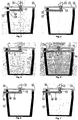
- a storage device according to the invention is designated with the number 1.
- the storage device consists of a box 2, having a lid 3, that can be fixed to the box 2 by a hinge or can be loosely or otherwise placed on the top of the box as explained later.
- a handle 4 is located on the lid 3, said handle is adapted to lock or unlock the lid from the box 2.
- Fig. 2 and fig 3 shows the box 2 having its lid 3 connected to the box 2 by a hinge 6.
- the handle 4 is equipped with a vertical extension part 7, that passes through the lid 3. This vertical part is equipped with a horizontal part 8.
- the handle can be moved in a horizontal direction fx. 20° in relation to the lengthwise direction of the box 2.
- the fig. 4 version differs from fig. 2 in that the lid 3 is equipped with a hole 12 in a vertical extension part 5 that is adapted to let the horizontal extended part 8 pass through the hole 12, and then contribute to a stronger lock of the lid 3 to the box 2.
- the fig. 5 version differs from fig. 4 in, that a further hole 10a is provided in the box 2 near the hinge 6, and again giving a stronger lock of the lid 3 to the box 2.
- the version in fig. 6 differs from the version in fig. 4 in that the extended vertical part 5 is placed outside the box 2, whereas the fig. 7 version shows combinations on the versions in fig. 4 -6 .
- the fig 8 version has in stead of a hinge a horizontal extended prolonged part 8b that is led through a hole 10b in the box 2.
- the fig. 9 version corresponds to the fig 8 . version but has its extended parts led through holes 12a, 12b in vertical parts of the lid.
- a not illustrated version corresponds to that of the fig. 7 version, but differs in that the extended vertical part 8d passes through two further holes in the box 2 and four extended vertical parts in the lid 3.
- Another not illustrated version corresponds to the aforementioned, also not illustrated version where the extended horizontal part is prolonged and led through two holes in the box 2 but only two holes 12, 12b in the vertical extended part 8c on the lids.
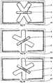
- the versions of fig. 12 - 14 have replaced the holes in the box 2 by at least one edge 14, that is adapted to retake up the extended horizontal part 8 of the handle 4.
- the fig. 15 and 16 versions correspond to the fig. 12 - 14 , but without hinges.
- the versions in fig 17 and 18 differ from the foregoing versions in that the handle 4 at its underside is equipped with an elastic taper 15, adapted to penetrate in a hole 16 in the lid 4.
- the extended vertical part 7 of the handle 4 is terminated by the horizontal part 8, that is moveable in a longer slot 10 and a narrower depression 24, both of which are provided in the wall of the box.
- the handle downwards his force will apply a movement to the handle downwards and enable the user to swing the handle in a horizontal movement, that offers him the possibility to lock and unlock the handle, so that the lid will be unlocked from or locked to the box, in the same way as already explained earlier.
- the lid can afterwards be released from the box 2, when the user presses the handle downwards and free the horizontal bar 8 from the depression 24. He can then swing the handle in an opposite horizontal direction in order to release the horizontal part 8 from the slot 10 and lift the lid from the box.
- the lengthwise direction of the storage device will not seek to be affected through the users hand forces. In normal position of a users hand it is directed about 20° in relation to direction of his view.
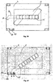
- the four last figures 24 - 27 demonstrate a storage box where the lid is releasable couple to the box by using special profiling between the lid and the box.
- Figure 24 designates couplings means in form of a top formed L-profile 27 in a lid that is adapted to be coupled to means 30 that are arranged to form a hole or a passage 23 that is adapted to accommodate a taper 19.
- This taper 19 terminates, cf. fig. 27 , in such a way, that when the taper is placed as shown in fig. 24 and 27 , then the lid will be locked or unlocked to the not shown box.
- the handle is moveable in horizontal direction in order to lock or unlock the lid to the box, incorporating all the advantages as ergonomic lift and so on.
Landscapes
- Engineering & Computer Science (AREA)
- Mechanical Engineering (AREA)
- Closures For Containers (AREA)
Claims (8)
- Dispositif de stockage (1) comprenant une boîte (2) munie d'un couvercle (3) et d'une poignée (4), dans lequel le couvercle (3) est placé sur la boîte (2) dans une direction verticale de la boîte (2), où le dispositif de stockage (1) a des moyens de verrouillage adaptés pour verrouiller le couvercle sur la boîte, et où les moyens de verrouillage sont constitués d'une partie mâle et d'une partie complémentaire, telle qu'une partie femelle ou un bord (14), dans lequel, à l'état verrouillé du couvercle (3) et de la boîte (2), la partie mâle est engagée avec la partie complémentaire et dans lequel à l'état déverrouillé du couvercle (3) et de la boîte (2), la partie mâle est désengagée de la partie complémentaire, ladite partie mâle constitue une partie de la poignée (4), tandis que la partie complémentaire est prévue dans la boîte (2) ou dans la boîte et le couvercle, dans lequel la boîte (2) a un contour horizontal rectangulaire définissant un axe longitudinal de la boîte et dans lequel la poignée (4) a une forme oblongue avec un axe longitudinal qui, lorsque le couvercle est déverrouillé par rapport à la boîte, coïncide avec l'axe longitudinal de la boîte, et dans lequel la poignée (4) est actionnée par un pivotement horizontal de sorte que, lorsque le couvercle (3) est verrouillé sur la boîte, alors l'axe longitudinal de la poignée soit déplacé d'environ 20° par rapport à l'axe longitudinal de la boîte, caractérisé en ce que la partie mâle a une partie verticale (7) s'étendant dans la direction verticale de la boîte (2) et traversant un trou dans le couvercle (3), et en ce que la partie verticale (7) se termine par une partie horizontale (8) formant la partie d'engagement avec la partie complémentaire, dans une direction horizontale qui est perpendiculaire à la direction verticale de la boîte (2).
- Dispositif de stockage selon la revendication 1, caractérisé en ce que la poignée (4) peut être déplacée par rapport à l'axe longitudinal de la boîte soit à gauche soit à droite par ledit déplacement approximatif de 20°, respectivement, selon qu'un utilisateur gaucher ou un utilisateur droitier l'utilise.
- Dispositif de stockage selon la revendication 1 ou 2, caractérisé en ce que la partie horizontale (8) est munie d'un cône orienté en oblique (19) au niveau de sa face inférieure qui s'étend dans la direction verticale de la boîte (2), dans lequel un tel cône (19) pénètre dans un trou (16) prévu dans le couvercle (3).
- Dispositif de stockage selon les revendications 1 à 3, caractérisé en ce que le couvercle (3) est articulé à la boîte, et en ce que la partie femelle est constituée d'un trou (10) dans une paroi latérale verticale de la boîte et d'un trou (12) dans une partie d'extension verticale (5) du couvercle (3) chevauchant verticalement ladite paroi latérale verticale de la boîte, ou la partie femelle est constituée de deux trous (12, 12a) dans deux parties d'extension verticales du couvercle et d'un trou (10) dans une paroi latérale verticale de la boîte s'étendant entre les deux parties d'extension, dans lequel, à l'état verrouillé du couvercle (3), la partie horizontale (8) pénètre dans chacun des trous associés.
- Dispositif de stockage selon les revendications 1 à 3, caractérisé en ce que le couvercle (3) est articulé à la boîte et en ce que la partie complémentaire est constituée d'un bord (14) dans la boîte défini par une saillie horizontale d'une paroi latérale verticale de la boîte sous lequel la partie horizontale se projette à l'état verrouillé du couvercle (3).
- Dispositif de stockage selon les revendications 1 à 3, caractérisé en ce que le couvercle (3) est articulé à la boîte et en ce que la partie complémentaire est constituée d'un bord (14) ou de deux bords (14) dans la boîte, définis chacun par une saillie horizontale d'une paroi latérale verticale de la boîte, et d'un trou dans une partie d'extension verticale (5) du couvercle (3) chevauchant verticalement ladite paroi latérale verticale de la boîte, dans lequel la partie horizontale fait saillie à travers le trou et à l'état verrouillé du couvercle (3) se projette sous chaque bord associé.
- Dispositif de stockage selon les revendications 1 à 3, caractérisé en ce que le couvercle (3) est verrouillé sur la boîte par la partie mâle dont la partie verticale (7) traverse un trou vertical dans le couvercle (3), ladite partie verticale (7) a deux parties horizontales opposées, et en ce que les parties complémentaires sont constituées de deux bords (14, 14a) dans la boîte, chacun d'eux étant défini par une saillie horizontale d'une paroi latérale verticale de la boîte ou en ce que les parties complémentaires sont constituées de deux trous, chacun étant prévu dans une partie d'extension verticale (5) du couvercle (3) et de deux bords dans la boîte (14, 14a), chacun d'eux étant défini par une saillie horizontale d'une paroi latérale verticale de la boîte, dans lequel chacune des parties horizontales opposées à l'état verrouillé du couvercle (3) se projette sous un bord associé des deux bords.
- Dispositif de stockage selon les revendications 1 à 7, caractérisé en ce que la poignée a une partie verticale étendue (16) qui traverse un trou dans le couvercle, ladite partie étendue se termine par un cône élastique (15) ayant de plus grandes dimensions que le trou dans le couvercle.
Applications Claiming Priority (3)
| Application Number | Priority Date | Filing Date | Title |
|---|---|---|---|
| DKPA201000518 | 2010-06-12 | ||
| DKPA201000597A DK201000597A (da) | 2010-07-06 | 2010-07-06 | Opbevaringsanordning bestående af tre dele |
| PCT/DK2011/000061 WO2012000497A1 (fr) | 2010-06-12 | 2011-06-14 | Boîte avec couvercle et poignée |
Publications (2)
| Publication Number | Publication Date |
|---|---|
| EP2582586A1 EP2582586A1 (fr) | 2013-04-24 |
| EP2582586B1 true EP2582586B1 (fr) | 2017-05-17 |
Family
ID=44508541
Family Applications (1)
| Application Number | Title | Priority Date | Filing Date |
|---|---|---|---|
| EP11743422.5A Active EP2582586B1 (fr) | 2010-06-12 | 2011-06-14 | Boîte de stockage avec couvercle et poignée |
Country Status (3)
| Country | Link |
|---|---|
| EP (1) | EP2582586B1 (fr) |
| ES (1) | ES2632569T3 (fr) |
| WO (1) | WO2012000497A1 (fr) |
Families Citing this family (32)
| Publication number | Priority date | Publication date | Assignee | Title |
|---|---|---|---|---|
| US11267119B2 (en) | 2015-12-14 | 2022-03-08 | Milwaukee Electric Tool Corporation | Storage device system |
| CA3108189C (fr) | 2016-05-02 | 2022-08-23 | Keter Plastic Ltd. | Ensemble de rangement et mecanisme de raccordement |
| WO2018213560A1 (fr) | 2017-05-17 | 2018-11-22 | Milwaukee Electric Tool Corporation | Système de dispositif de stockage |
| CN107117365B (zh) * | 2017-05-31 | 2022-11-29 | 苏州市职业大学 | 具备儿童防护功能的三点开启式药品包装盒 |
| USD872478S1 (en) | 2017-06-12 | 2020-01-14 | Yeti Coolers, Llc | Container |
| US12108853B2 (en) | 2019-01-06 | 2024-10-08 | Yeti Coolers, Llc | Luggage system |
| USD838984S1 (en) | 2017-06-12 | 2019-01-29 | Yeti Coolers, Llc | Container |
| USD838983S1 (en) | 2017-06-12 | 2019-01-29 | Yeti Coolers, Llc | Container |
| AU201717615S (en) | 2017-06-12 | 2018-01-15 | Yeti Coolers | Container |
| USD828029S1 (en) | 2017-06-12 | 2018-09-11 | Yeti Coolers, Llc | Container |
| USD840150S1 (en) | 2017-06-12 | 2019-02-12 | Yeti Coolers, Llc | Container |
| USD828028S1 (en) | 2017-06-12 | 2018-09-11 | Yeti Coolers, Llc | Container |
| USD873020S1 (en) | 2017-06-12 | 2020-01-21 | Yeti Coolers, Llc | Container |
| JP7101199B2 (ja) | 2017-06-12 | 2022-07-14 | イエティ クーラーズ エルエルシー | コンテナおよびラッチング・システム |
| USD869160S1 (en) | 2017-06-12 | 2019-12-10 | Yeti Coolers, Llc | Container |
| USD872485S1 (en) | 2017-06-12 | 2020-01-14 | Yeti Coolers, Llc | Container |
| US11976498B2 (en) | 2017-06-12 | 2024-05-07 | Yeti Coolers, Llc | Container and latching system |
| US11685573B2 (en) | 2017-06-12 | 2023-06-27 | Yeti Coolers, Llc | Carry strap for container |
| WO2019028041A1 (fr) | 2017-07-31 | 2019-02-07 | Milwaukee Electric Tool Corporation | Système de dispositif de rangement |
| CN111867785A (zh) | 2018-01-24 | 2020-10-30 | 米沃奇电动工具公司 | 工具储存装置 |
| USD904829S1 (en) | 2018-12-11 | 2020-12-15 | Yeti Coolers, Llc | Container accessories |
| USD907445S1 (en) | 2018-12-11 | 2021-01-12 | Yeti Coolers, Llc | Container accessories |
| JP7303313B2 (ja) | 2019-01-06 | 2023-07-04 | イエティ クーラーズ エルエルシー | 荷物システム |
| US12225993B2 (en) | 2019-01-06 | 2025-02-18 | Yeti Coolers, Llc | Luggage system |
| IL269564B2 (en) | 2019-09-23 | 2023-11-01 | Keter Home & Garden Products Ltd | Sawhorse |
| USD961926S1 (en) | 2020-06-30 | 2022-08-30 | Yeti Coolers, Llc | Luggage |
| USD951643S1 (en) | 2020-06-30 | 2022-05-17 | Yeti Coolers, Llc | Luggage |
| USD954436S1 (en) | 2020-06-30 | 2022-06-14 | Yeti Coolers, Llc | Luggage |
| USD963344S1 (en) | 2020-06-30 | 2022-09-13 | Yeti Coolers, Llc | Luggage |
| USD994438S1 (en) | 2020-12-16 | 2023-08-08 | Yeti Coolers, Llc | Container |
| USD985937S1 (en) | 2020-12-16 | 2023-05-16 | Yeti Coolers, Llc | Container |
| USD960648S1 (en) | 2020-12-16 | 2022-08-16 | Yeti Coolers, Llc | Container accessory |
Family Cites Families (6)
| Publication number | Priority date | Publication date | Assignee | Title |
|---|---|---|---|---|
| US2437099A (en) * | 1945-07-25 | 1948-03-02 | Krupp Louis | Combination handle and closure means for handbags |
| DE2322358A1 (de) * | 1973-05-03 | 1974-11-14 | Uwe Dr Med Dr Phil Stocksmeier | Vorrichtung zum tragen einer last |
| ES1027080Y (es) * | 1994-02-17 | 1995-01-16 | Ind Tayg S L | Nueva caja para herramientas. |
| US7246718B2 (en) * | 2003-10-02 | 2007-07-24 | Zag Industries Ltd. | Toolbox with handle having cover locking mechanism |
| EP2346741B1 (fr) | 2008-05-19 | 2015-04-08 | TTS Tooltechnic Systems AG & Co. KG | Disposition de stockage comprenant deux parties, par exemple deux boîtiers ou un boîtier et un couvercle |
| DE102008025489A1 (de) | 2008-05-28 | 2009-12-24 | Siemens Aktiengesellschaft | Verfahren und System zum Überwachen eines sicherheitsbezogenen Systems |
-
2011
- 2011-06-14 WO PCT/DK2011/000061 patent/WO2012000497A1/fr not_active Ceased
- 2011-06-14 ES ES11743422.5T patent/ES2632569T3/es active Active
- 2011-06-14 EP EP11743422.5A patent/EP2582586B1/fr active Active
Also Published As
| Publication number | Publication date |
|---|---|
| EP2582586A1 (fr) | 2013-04-24 |
| WO2012000497A1 (fr) | 2012-01-05 |
| ES2632569T3 (es) | 2017-09-14 |
Similar Documents
| Publication | Publication Date | Title |
|---|---|---|
| EP2582586B1 (fr) | Boîte de stockage avec couvercle et poignée | |
| EP1848873B1 (fr) | Dispositif de verrouillage de type à pression | |
| CA2694801C (fr) | Systeme d'entreposage integre avec contenants verrouillables | |
| EP2474393B1 (fr) | Récipient avec verrou | |
| USD534448S1 (en) | Authentication device | |
| US9131770B2 (en) | Containers | |
| EP2436492B1 (fr) | Ensemble formant récipient | |
| JP5836877B2 (ja) | 工具収納ケース | |
| USD589779S1 (en) | Ergonomic locking pin | |
| US20150274362A1 (en) | Toolbox | |
| CN101115412B (zh) | 箱子 | |
| CN109414810A (zh) | 可堆叠的系统容器 | |
| US20150320207A1 (en) | Bookcase | |
| US11414878B2 (en) | Unlocking structure of workbench ladder | |
| JP2010137920A (ja) | スライド式蓋を有するロックボックス | |
| CN104960813A (zh) | 容器 | |
| CA2793820A1 (fr) | Ensemble de boite a outils | |
| US10004350B1 (en) | Knife holder | |
| EP1744961A1 (fr) | Systeme de verrouillage dote d'une poignee a utiliser dans un contenant | |
| USD602340S1 (en) | Modular panel key lock | |
| KR20180038172A (ko) | 접이식 도어용 잠금장치 | |
| US20070130731A1 (en) | Case handle for protective cases | |
| US20060181182A1 (en) | Cabinet drawer drivingly connected locking mechanism | |
| CN204751106U (zh) | 容器 | |
| KR101622772B1 (ko) | 조립식 수납함 |
Legal Events
| Date | Code | Title | Description |
|---|---|---|---|
| PUAI | Public reference made under article 153(3) epc to a published international application that has entered the european phase |
Free format text: ORIGINAL CODE: 0009012 |
|
| 17P | Request for examination filed |
Effective date: 20130115 |
|
| AK | Designated contracting states |
Kind code of ref document: A1 Designated state(s): AL AT BE BG CH CY CZ DE DK EE ES FI FR GB GR HR HU IE IS IT LI LT LU LV MC MK MT NL NO PL PT RO RS SE SI SK SM TR |
|
| DAX | Request for extension of the european patent (deleted) | ||
| RAP1 | Party data changed (applicant data changed or rights of an application transferred) |
Owner name: TTS TOOLTECHNIC SYSTEMS AG & CO. KG |
|
| 17Q | First examination report despatched |
Effective date: 20140430 |
|
| GRAP | Despatch of communication of intention to grant a patent |
Free format text: ORIGINAL CODE: EPIDOSNIGR1 |
|
| INTG | Intention to grant announced |
Effective date: 20161222 |
|
| GRAS | Grant fee paid |
Free format text: ORIGINAL CODE: EPIDOSNIGR3 |
|
| GRAA | (expected) grant |
Free format text: ORIGINAL CODE: 0009210 |
|
| AK | Designated contracting states |
Kind code of ref document: B1 Designated state(s): AL AT BE BG CH CY CZ DE DK EE ES FI FR GB GR HR HU IE IS IT LI LT LU LV MC MK MT NL NO PL PT RO RS SE SI SK SM TR |
|
| REG | Reference to a national code |
Ref country code: GB Ref legal event code: FG4D |
|
| REG | Reference to a national code |
Ref country code: CH Ref legal event code: EP |
|
| REG | Reference to a national code |
Ref country code: IE Ref legal event code: FG4D |
|
| REG | Reference to a national code |
Ref country code: CH Ref legal event code: NV Representative=s name: TROESCH SCHEIDEGGER WERNER AG, CH Ref country code: AT Ref legal event code: REF Ref document number: 894218 Country of ref document: AT Kind code of ref document: T Effective date: 20170615 |
|
| REG | Reference to a national code |
Ref country code: DE Ref legal event code: R096 Ref document number: 602011038043 Country of ref document: DE Ref country code: FR Ref legal event code: PLFP Year of fee payment: 7 |
|
| REG | Reference to a national code |
Ref country code: SE Ref legal event code: TRGR |
|
| REG | Reference to a national code |
Ref country code: NL Ref legal event code: FP |
|
| REG | Reference to a national code |
Ref country code: ES Ref legal event code: FG2A Ref document number: 2632569 Country of ref document: ES Kind code of ref document: T3 Effective date: 20170914 |
|
| REG | Reference to a national code |
Ref country code: LT Ref legal event code: MG4D |
|
| PG25 | Lapsed in a contracting state [announced via postgrant information from national office to epo] |
Ref country code: LT Free format text: LAPSE BECAUSE OF FAILURE TO SUBMIT A TRANSLATION OF THE DESCRIPTION OR TO PAY THE FEE WITHIN THE PRESCRIBED TIME-LIMIT Effective date: 20170517 Ref country code: HR Free format text: LAPSE BECAUSE OF FAILURE TO SUBMIT A TRANSLATION OF THE DESCRIPTION OR TO PAY THE FEE WITHIN THE PRESCRIBED TIME-LIMIT Effective date: 20170517 Ref country code: GR Free format text: LAPSE BECAUSE OF FAILURE TO SUBMIT A TRANSLATION OF THE DESCRIPTION OR TO PAY THE FEE WITHIN THE PRESCRIBED TIME-LIMIT Effective date: 20170818 Ref country code: NO Free format text: LAPSE BECAUSE OF FAILURE TO SUBMIT A TRANSLATION OF THE DESCRIPTION OR TO PAY THE FEE WITHIN THE PRESCRIBED TIME-LIMIT Effective date: 20170817 Ref country code: FI Free format text: LAPSE BECAUSE OF FAILURE TO SUBMIT A TRANSLATION OF THE DESCRIPTION OR TO PAY THE FEE WITHIN THE PRESCRIBED TIME-LIMIT Effective date: 20170517 |
|
| PG25 | Lapsed in a contracting state [announced via postgrant information from national office to epo] |
Ref country code: LV Free format text: LAPSE BECAUSE OF FAILURE TO SUBMIT A TRANSLATION OF THE DESCRIPTION OR TO PAY THE FEE WITHIN THE PRESCRIBED TIME-LIMIT Effective date: 20170517 Ref country code: PL Free format text: LAPSE BECAUSE OF FAILURE TO SUBMIT A TRANSLATION OF THE DESCRIPTION OR TO PAY THE FEE WITHIN THE PRESCRIBED TIME-LIMIT Effective date: 20170517 Ref country code: RS Free format text: LAPSE BECAUSE OF FAILURE TO SUBMIT A TRANSLATION OF THE DESCRIPTION OR TO PAY THE FEE WITHIN THE PRESCRIBED TIME-LIMIT Effective date: 20170517 Ref country code: BG Free format text: LAPSE BECAUSE OF FAILURE TO SUBMIT A TRANSLATION OF THE DESCRIPTION OR TO PAY THE FEE WITHIN THE PRESCRIBED TIME-LIMIT Effective date: 20170817 Ref country code: IS Free format text: LAPSE BECAUSE OF FAILURE TO SUBMIT A TRANSLATION OF THE DESCRIPTION OR TO PAY THE FEE WITHIN THE PRESCRIBED TIME-LIMIT Effective date: 20170917 |
|
| PG25 | Lapsed in a contracting state [announced via postgrant information from national office to epo] |
Ref country code: DK Free format text: LAPSE BECAUSE OF FAILURE TO SUBMIT A TRANSLATION OF THE DESCRIPTION OR TO PAY THE FEE WITHIN THE PRESCRIBED TIME-LIMIT Effective date: 20170517 Ref country code: CZ Free format text: LAPSE BECAUSE OF FAILURE TO SUBMIT A TRANSLATION OF THE DESCRIPTION OR TO PAY THE FEE WITHIN THE PRESCRIBED TIME-LIMIT Effective date: 20170517 Ref country code: EE Free format text: LAPSE BECAUSE OF FAILURE TO SUBMIT A TRANSLATION OF THE DESCRIPTION OR TO PAY THE FEE WITHIN THE PRESCRIBED TIME-LIMIT Effective date: 20170517 Ref country code: SK Free format text: LAPSE BECAUSE OF FAILURE TO SUBMIT A TRANSLATION OF THE DESCRIPTION OR TO PAY THE FEE WITHIN THE PRESCRIBED TIME-LIMIT Effective date: 20170517 Ref country code: RO Free format text: LAPSE BECAUSE OF FAILURE TO SUBMIT A TRANSLATION OF THE DESCRIPTION OR TO PAY THE FEE WITHIN THE PRESCRIBED TIME-LIMIT Effective date: 20170517 |
|
| REG | Reference to a national code |
Ref country code: DE Ref legal event code: R097 Ref document number: 602011038043 Country of ref document: DE |
|
| PG25 | Lapsed in a contracting state [announced via postgrant information from national office to epo] |
Ref country code: SM Free format text: LAPSE BECAUSE OF FAILURE TO SUBMIT A TRANSLATION OF THE DESCRIPTION OR TO PAY THE FEE WITHIN THE PRESCRIBED TIME-LIMIT Effective date: 20170517 |
|
| REG | Reference to a national code |
Ref country code: IE Ref legal event code: MM4A |
|
| PLBE | No opposition filed within time limit |
Free format text: ORIGINAL CODE: 0009261 |
|
| STAA | Information on the status of an ep patent application or granted ep patent |
Free format text: STATUS: NO OPPOSITION FILED WITHIN TIME LIMIT |
|
| 26N | No opposition filed |
Effective date: 20180220 |
|
| PG25 | Lapsed in a contracting state [announced via postgrant information from national office to epo] |
Ref country code: LU Free format text: LAPSE BECAUSE OF NON-PAYMENT OF DUE FEES Effective date: 20170614 Ref country code: IE Free format text: LAPSE BECAUSE OF NON-PAYMENT OF DUE FEES Effective date: 20170614 |
|
| PG25 | Lapsed in a contracting state [announced via postgrant information from national office to epo] |
Ref country code: SI Free format text: LAPSE BECAUSE OF FAILURE TO SUBMIT A TRANSLATION OF THE DESCRIPTION OR TO PAY THE FEE WITHIN THE PRESCRIBED TIME-LIMIT Effective date: 20170517 |
|
| REG | Reference to a national code |
Ref country code: FR Ref legal event code: PLFP Year of fee payment: 8 |
|
| PG25 | Lapsed in a contracting state [announced via postgrant information from national office to epo] |
Ref country code: MT Free format text: LAPSE BECAUSE OF NON-PAYMENT OF DUE FEES Effective date: 20170614 |
|
| PG25 | Lapsed in a contracting state [announced via postgrant information from national office to epo] |
Ref country code: HU Free format text: LAPSE BECAUSE OF FAILURE TO SUBMIT A TRANSLATION OF THE DESCRIPTION OR TO PAY THE FEE WITHIN THE PRESCRIBED TIME-LIMIT; INVALID AB INITIO Effective date: 20110614 Ref country code: MC Free format text: LAPSE BECAUSE OF FAILURE TO SUBMIT A TRANSLATION OF THE DESCRIPTION OR TO PAY THE FEE WITHIN THE PRESCRIBED TIME-LIMIT Effective date: 20170517 |
|
| PG25 | Lapsed in a contracting state [announced via postgrant information from national office to epo] |
Ref country code: CY Free format text: LAPSE BECAUSE OF NON-PAYMENT OF DUE FEES Effective date: 20170517 |
|
| PG25 | Lapsed in a contracting state [announced via postgrant information from national office to epo] |
Ref country code: MK Free format text: LAPSE BECAUSE OF FAILURE TO SUBMIT A TRANSLATION OF THE DESCRIPTION OR TO PAY THE FEE WITHIN THE PRESCRIBED TIME-LIMIT Effective date: 20170517 |
|
| REG | Reference to a national code |
Ref country code: AT Ref legal event code: UEP Ref document number: 894218 Country of ref document: AT Kind code of ref document: T Effective date: 20170517 |
|
| PG25 | Lapsed in a contracting state [announced via postgrant information from national office to epo] |
Ref country code: TR Free format text: LAPSE BECAUSE OF FAILURE TO SUBMIT A TRANSLATION OF THE DESCRIPTION OR TO PAY THE FEE WITHIN THE PRESCRIBED TIME-LIMIT Effective date: 20170517 |
|
| PG25 | Lapsed in a contracting state [announced via postgrant information from national office to epo] |
Ref country code: PT Free format text: LAPSE BECAUSE OF FAILURE TO SUBMIT A TRANSLATION OF THE DESCRIPTION OR TO PAY THE FEE WITHIN THE PRESCRIBED TIME-LIMIT Effective date: 20170517 |
|
| PG25 | Lapsed in a contracting state [announced via postgrant information from national office to epo] |
Ref country code: AL Free format text: LAPSE BECAUSE OF FAILURE TO SUBMIT A TRANSLATION OF THE DESCRIPTION OR TO PAY THE FEE WITHIN THE PRESCRIBED TIME-LIMIT Effective date: 20170517 |
|
| PGFP | Annual fee paid to national office [announced via postgrant information from national office to epo] |
Ref country code: DE Payment date: 20250605 Year of fee payment: 15 |
|
| PGFP | Annual fee paid to national office [announced via postgrant information from national office to epo] |
Ref country code: GB Payment date: 20250620 Year of fee payment: 15 |
|
| PGFP | Annual fee paid to national office [announced via postgrant information from national office to epo] |
Ref country code: NL Payment date: 20250618 Year of fee payment: 15 Ref country code: BE Payment date: 20250617 Year of fee payment: 15 |
|
| PGFP | Annual fee paid to national office [announced via postgrant information from national office to epo] |
Ref country code: FR Payment date: 20250624 Year of fee payment: 15 |
|
| PGFP | Annual fee paid to national office [announced via postgrant information from national office to epo] |
Ref country code: AT Payment date: 20250616 Year of fee payment: 15 |
|
| PGFP | Annual fee paid to national office [announced via postgrant information from national office to epo] |
Ref country code: SE Payment date: 20250618 Year of fee payment: 15 |
|
| PGFP | Annual fee paid to national office [announced via postgrant information from national office to epo] |
Ref country code: ES Payment date: 20250718 Year of fee payment: 15 |
|
| PGFP | Annual fee paid to national office [announced via postgrant information from national office to epo] |
Ref country code: IT Payment date: 20250630 Year of fee payment: 15 |
|
| PGFP | Annual fee paid to national office [announced via postgrant information from national office to epo] |
Ref country code: CH Payment date: 20250701 Year of fee payment: 15 |
|
| REG | Reference to a national code |
Ref country code: DE Ref legal event code: R081 Ref document number: 602011038043 Country of ref document: DE Owner name: TTS TOOLTECHNIC SYSTEMS SE & CO. KG, DE Free format text: FORMER OWNER: TTS TOOLTECHNIC SYSTEMS AG & CO. KG, 73240 WENDLINGEN, DE |