EP2583067B1 - Verfahren zur herstellung eines magnetisch-induktiven durchflussmessgeräts - Google Patents
Verfahren zur herstellung eines magnetisch-induktiven durchflussmessgeräts Download PDFInfo
- Publication number
- EP2583067B1 EP2583067B1 EP11719252.6A EP11719252A EP2583067B1 EP 2583067 B1 EP2583067 B1 EP 2583067B1 EP 11719252 A EP11719252 A EP 11719252A EP 2583067 B1 EP2583067 B1 EP 2583067B1
- Authority
- EP
- European Patent Office
- Prior art keywords
- electrode
- measuring tube
- plastic
- electromagnetic flowmeter
- fabrication
- Prior art date
- Legal status (The legal status is an assumption and is not a legal conclusion. Google has not performed a legal analysis and makes no representation as to the accuracy of the status listed.)
- Active
Links
- 238000000034 method Methods 0.000 title claims description 28
- 239000004033 plastic Substances 0.000 claims description 57
- 238000007789 sealing Methods 0.000 claims description 38
- 238000004519 manufacturing process Methods 0.000 claims description 18
- 230000000295 complement effect Effects 0.000 claims description 10
- 229920000642 polymer Polymers 0.000 claims description 7
- 239000004020 conductor Substances 0.000 claims description 3
- 238000004382 potting Methods 0.000 claims 3
- 239000007788 liquid Substances 0.000 claims 1
- 230000002093 peripheral effect Effects 0.000 claims 1
- 230000015572 biosynthetic process Effects 0.000 description 7
- 238000005755 formation reaction Methods 0.000 description 7
- 239000000463 material Substances 0.000 description 5
- 238000001746 injection moulding Methods 0.000 description 4
- 238000004023 plastic welding Methods 0.000 description 4
- 238000003466 welding Methods 0.000 description 4
- 238000004873 anchoring Methods 0.000 description 3
- 229910001220 stainless steel Inorganic materials 0.000 description 3
- 239000010935 stainless steel Substances 0.000 description 3
- 239000000126 substance Substances 0.000 description 3
- 238000005266 casting Methods 0.000 description 2
- 230000008878 coupling Effects 0.000 description 2
- 238000010168 coupling process Methods 0.000 description 2
- 238000005859 coupling reaction Methods 0.000 description 2
- 239000012777 electrically insulating material Substances 0.000 description 2
- 238000005538 encapsulation Methods 0.000 description 2
- 238000005516 engineering process Methods 0.000 description 2
- 238000005259 measurement Methods 0.000 description 2
- 238000000465 moulding Methods 0.000 description 2
- BASFCYQUMIYNBI-UHFFFAOYSA-N platinum Chemical compound [Pt] BASFCYQUMIYNBI-UHFFFAOYSA-N 0.000 description 2
- 241000191291 Abies alba Species 0.000 description 1
- 229920002943 EPDM rubber Polymers 0.000 description 1
- 229920002449 FKM Polymers 0.000 description 1
- 239000004696 Poly ether ether ketone Substances 0.000 description 1
- RTAQQCXQSZGOHL-UHFFFAOYSA-N Titanium Chemical compound [Ti] RTAQQCXQSZGOHL-UHFFFAOYSA-N 0.000 description 1
- 238000013459 approach Methods 0.000 description 1
- JUPQTSLXMOCDHR-UHFFFAOYSA-N benzene-1,4-diol;bis(4-fluorophenyl)methanone Chemical compound OC1=CC=C(O)C=C1.C1=CC(F)=CC=C1C(=O)C1=CC=C(F)C=C1 JUPQTSLXMOCDHR-UHFFFAOYSA-N 0.000 description 1
- 239000000919 ceramic Substances 0.000 description 1
- 239000002800 charge carrier Substances 0.000 description 1
- 238000000576 coating method Methods 0.000 description 1
- 230000001419 dependent effect Effects 0.000 description 1
- 238000013461 design Methods 0.000 description 1
- 238000011161 development Methods 0.000 description 1
- 230000018109 developmental process Effects 0.000 description 1
- 238000007598 dipping method Methods 0.000 description 1
- 238000009826 distribution Methods 0.000 description 1
- 239000003651 drinking water Substances 0.000 description 1
- 235000020188 drinking water Nutrition 0.000 description 1
- 230000000694 effects Effects 0.000 description 1
- 230000005520 electrodynamics Effects 0.000 description 1
- 229910000856 hastalloy Inorganic materials 0.000 description 1
- 230000006698 induction Effects 0.000 description 1
- 230000001939 inductive effect Effects 0.000 description 1
- 238000009434 installation Methods 0.000 description 1
- 238000005304 joining Methods 0.000 description 1
- 239000000696 magnetic material Substances 0.000 description 1
- 230000005389 magnetism Effects 0.000 description 1
- 239000000203 mixture Substances 0.000 description 1
- 230000035515 penetration Effects 0.000 description 1
- 229910052697 platinum Inorganic materials 0.000 description 1
- 229920002530 polyetherether ketone Polymers 0.000 description 1
- 238000012545 processing Methods 0.000 description 1
- 238000010079 rubber tapping Methods 0.000 description 1
- 229910052715 tantalum Inorganic materials 0.000 description 1
- GUVRBAGPIYLISA-UHFFFAOYSA-N tantalum atom Chemical compound [Ta] GUVRBAGPIYLISA-UHFFFAOYSA-N 0.000 description 1
- 229920001169 thermoplastic Polymers 0.000 description 1
- 239000004416 thermosoftening plastic Substances 0.000 description 1
- 229910052719 titanium Inorganic materials 0.000 description 1
- 239000010936 titanium Substances 0.000 description 1
- 239000002351 wastewater Substances 0.000 description 1
Images


Classifications
-
- B—PERFORMING OPERATIONS; TRANSPORTING
- B05—SPRAYING OR ATOMISING IN GENERAL; APPLYING FLUENT MATERIALS TO SURFACES, IN GENERAL
- B05D—PROCESSES FOR APPLYING FLUENT MATERIALS TO SURFACES, IN GENERAL
- B05D1/00—Processes for applying liquids or other fluent materials
-
- G—PHYSICS
- G01—MEASURING; TESTING
- G01F—MEASURING VOLUME, VOLUME FLOW, MASS FLOW OR LIQUID LEVEL; METERING BY VOLUME
- G01F1/00—Measuring the volume flow or mass flow of fluid or fluent solid material wherein the fluid passes through a meter in a continuous flow
- G01F1/56—Measuring the volume flow or mass flow of fluid or fluent solid material wherein the fluid passes through a meter in a continuous flow by using electric or magnetic effects
- G01F1/58—Measuring the volume flow or mass flow of fluid or fluent solid material wherein the fluid passes through a meter in a continuous flow by using electric or magnetic effects by electromagnetic flowmeters
- G01F1/584—Measuring the volume flow or mass flow of fluid or fluent solid material wherein the fluid passes through a meter in a continuous flow by using electric or magnetic effects by electromagnetic flowmeters constructions of electrodes, accessories therefor
-
- Y—GENERAL TAGGING OF NEW TECHNOLOGICAL DEVELOPMENTS; GENERAL TAGGING OF CROSS-SECTIONAL TECHNOLOGIES SPANNING OVER SEVERAL SECTIONS OF THE IPC; TECHNICAL SUBJECTS COVERED BY FORMER USPC CROSS-REFERENCE ART COLLECTIONS [XRACs] AND DIGESTS
- Y10—TECHNICAL SUBJECTS COVERED BY FORMER USPC
- Y10T—TECHNICAL SUBJECTS COVERED BY FORMER US CLASSIFICATION
- Y10T29/00—Metal working
- Y10T29/49—Method of mechanical manufacture
- Y10T29/49002—Electrical device making
- Y10T29/49117—Conductor or circuit manufacturing
- Y10T29/49204—Contact or terminal manufacturing
- Y10T29/49208—Contact or terminal manufacturing by assembling plural parts
- Y10T29/4922—Contact or terminal manufacturing by assembling plural parts with molding of insulation
Definitions
- the present invention relates to a method for producing a magneto-inductive flowmeter by encapsulating an elongated electrode with liquefied plastic and a magnetic-inductive flowmeter produced by the method according to the invention.
- Magnetic-inductive flowmeters use the principle of electrodynamic induction for volumetric flow measurement and are known from a variety of publications.
- Charge carriers of the medium moved perpendicularly to a magnetic field induce a measuring voltage in measuring electrodes which are essentially perpendicular to the direction of flow of the medium and perpendicular to the direction of the magnetic field.
- the measuring voltage induced in the measuring electrodes is proportional to the flow velocity of the medium, averaged over the cross section of the measuring tube, ie proportional to the volume flow. If the density of the medium is known, the mass flow in the pipeline or in the measuring tube can be determined.
- the measuring voltage is usually tapped via a pair of measuring electrodes, which is arranged with respect to the coordinate along the measuring tube axis in the region of maximum magnetic field strength and where consequently the maximum measuring voltage is to be expected.
- the electrodes are usually galvanically coupled to the medium; However, magnetic-inductive flowmeters with non-contact capacitive coupling electrodes are also known.
- the measuring tube can either be made of an electrically conductive, non-magnetic material, such as stainless steel, or consist of an electrically insulating material. If the measuring tube is made of an electrically conductive material, then it must be lined in the area coming into contact with the medium with a liner made of an electrically insulating material. Depending on the temperature and medium, the liner consists, for example, of a thermoplastic, a duroplastic or an elastomeric plastic. However, magnetic-inductive flow meters with a ceramic lining are also known.
- An electrode can essentially be subdivided into an electrode head which at least partially comes into contact with a medium which flows through the measuring tube and an electrode shaft which is introduced almost completely into the wall of the measuring tube.
- the electrodes are in addition to the magnet system, the central components of a magnetic-inductive flowmeter. In the design and arrangement of the electrodes, care must be taken that they can be mounted as simply as possible in the measuring tube and that no leakage problems subsequently occur during measuring operation; In addition, the electrodes should be distinguished by a sensitive and at the same time low-interference measurement signal acquisition.
- measuring electrodes which serve to tap a measuring signal
- additional electrodes in the form of reference or ground electrodes are often installed in the measuring tube, which serve to measure an electrical reference potential or to detect partially filled measuring tubes.
- the electrodes usually have elongated electrode shanks, with diversely shaped notches.
- the WO 2009/071615 A2 shows an electrode with an electrode shaft, with a plurality of frusto-conical sealing lips, wherein the diameters of the sealing lips vary in size.
- electrodes together with other components of a magnetic-inductive flowmeter are cast with the measuring tube in a separate or in a common plastic encapsulation.
- the WO 10015534 A1 shows a magnetic-inductive flowmeter with a sensor, wherein the sensor comprises a flowed through by a medium measuring tube, a magnetic system for generating a Magnetic field comprises, at least one introduced into the measuring tube electrode for detecting an electrical voltage, wherein a fastening means is provided, which serves for fixing the electrode to the measuring tube, wherein the fastening means consists at least partially of plastic, and wherein the fastening means by a plastic welding technique is connected to the measuring tube, and a method for manufacturing a magnetic-inductive flowmeter, wherein the magnetic-inductive flowmeter comprises a measuring tube, wherein the measuring tube has at least one bore, wherein an electrode is introduced into the bore, wherein the electrode by means of a plastic Welding technology is attached to the measuring tube.
- the electrode has at least one sealing element which seals the measuring tube in the region of the bore, wherein the sealing element can be partially introduced into a recess of the electrode shaft.
- the sealing element can be partially introduced into a recess of the electrode shaft.
- Fig. 5A of the document DE 10 2007 004 826 A1 shows a detailed view of a multi-part measuring electrode of a flow meter, in which a first measuring electrode part 26 is embedded in a Meßrohrwandung 2. It can be seen at the point 28 a punctiform shape. It can also be seen from FIG. 5A that the measuring tube wall protrudes into this shape.
- the publication WO 2010/015534 A1 discloses a flow meter in which a determination of a measuring electrode by means of a plastic welding technique. The measuring electrode has a preformed recess 13 and an O-ring, which is arranged loosely in the molding.
- the publication WO 2008/059020 A1 discloses a measuring electrode having a Christmas tree structure. Here, barbs projecting laterally out of the electrode body and the mushroom-head structure of the electrode ensure a better sealing effect.
- the object of the invention is to provide a magneto-inductive measuring device with a cost-effective to produce and highly effective sealing electrode assembly.
- the elongated electrode has at least one longitudinal extension along a longitudinal axis, which is greater than a transverse extent of the electrode, perpendicular to the longitudinal axis. In particular, the ratio of longitudinal extent to transverse extent is greater than 2.
- the electrode may first be completely encased in plastic before the excess plastic is removed again. However, a sheathing is preferred the electrode with plastic, wherein at least the electrode head is not covered by plastic. Furthermore, at the opposite end of the electrode head, shaft end of the electrode also no plastic is provided to electrically contact the electrode.
- the elongated electrode is positioned in an embodiment of the invention in the operational magnetic-inductive flowmeter with its longitudinal axis perpendicular to the measuring tube axis in the measuring tube wall.
- the electrode is made with a circumferential circumferential recess, for example made of stainless steel, or even of an electrically conductive plastic. If the electrode has a circular cross-section transverse to the longitudinal axis of the electrode, the recess is radially encircling. If the groove cross-sectionally rectangular, can then be spoken of an annular groove. In other embodiments of the electrode, the cross sections may be elliptical, oval or polygonal. The punctures may also have various cross-sectional shapes, e.g. rectangular or semicircular or sawtooth.
- an elastic sealing ring When an elastic sealing ring is positioned on the electrode, it is sealingly applied to the electrode surface, e.g. clamped on the jacket of a cylindrically shaped electrode, wherein the sealing ring, in this example a so-called O-ring, then an inner, free diameter, less than the diameter of the jacket of the electrode at the position of the sealing ring on the electrode.
- the sealing ring is in particular positioned on the electrode before the electrode is positioned in the tool; but in any case before the electrode is covered with liquefied plastic.
- the sealing ring is positioned in a recess of the electrode, which is provided for receiving the sealing ring and designed accordingly.
- the shape and size of the sealing ring and the first groove are matched; for example, complementary to each other.
- the elastic sealing ring is at least partially covered with plastic.
- the temperature of the plastic is kept below 350 ° C, especially below 200 ° C. processing and material of the plastic and material of the sealing ring are also matched.
- the sealing ring consists for example of EPDM, Viton or Kalrez.
- the sealing ring seals fluid-tight both with respect to the plastic surrounding the electrode and with respect to the electrode itself.
- Further punctures may be provided in the electrode surface, for axial fixation or determination of the electrode or for Leckagewegverinrung. These also have rectangular or semicircular or sawtooth cross sections. At least one of these further cross-sections, if present, at least partially filled with plastic during manufacture.
- the tooth spaces are at least partially filled with plastic.
- an electrode according to the invention has a collar-shaped collar.
- Another example shows an electrode according to the invention with radially encircling formations for anchoring the electrode and for lengthening the leakage paths. In both examples, the formations also be obtained by recesses are made in addition to the formations that make the formations appear only as such.
- the electrode is aligned in the tool, for example by means of a first and second contour.
- the electrode has e.g. a conical electrode head and / or a bore in the opposite shaft end.
- the tool or a core forming the lumen of the measuring tube has the complementary and compatible with the contours of the electrode, i. Contours with the contours of the electrode agree with each other.
- the electrode is so e.g. with its conical electrode head to a complementary conical depression in the core for the, in later operation of the electromagnetic flowmeter flow-guiding, lumen of the measuring tube and thus form-fitting manner connected to the core.
- the electrode can also have a groove instead of a bore in the end opposite the electrode head of the electrode shaft, or can also be aligned by magnetism in the tool and held during the casting process.
- the electrode is encapsulated with plastic, which simultaneously forms the measuring tube.
- the measuring tube in a first method step, is poured with a space provided for the positioning of the electrode and then the electrode inserted into this space and molded with plastic, the prefabricated measuring tube serves as a tool, and the sheath of the electrode with plastic , which is produced in the second process step, is also part of the measuring tube.
- Further embodiments show the electrode encased in plastic, wherein the electrode is used together with the jacket in a bore in the measuring tube wall and, for example, subsequently welded thereto, in particular with ultrasonic welding.
- the electrode is connected to the core by positive locking Aligning the second and fourth complementary contour is positioned to each other, these parts of the measuring tube, for example, two identical half shells, then connected to other parts with each other, in particular welded together cohesively.
- the present invention relates to a method for producing a magneto-inductive flowmeter, in particular the process measuring technology, for determining the flow of a measuring medium through a measuring tube.
- a cross section through an electrode assembly of a magnetic-inductive flowmeter is shown.
- the electrode 1 is introduced into the wall 2 of a measuring tube and has an electrode shaft 3 and an electrode head 4 at least partially wetted by the medium 5 in the measuring operation.
- Measuring substances 5 can be both pure substances and mixtures.
- the electrode head 4, in the region in which it projects into the lumen of the measuring tube, has a conical shape.
- the electrode shaft 3 has a cylindrical basic shape.
- a cross section through the electrode 1 in a plane parallel to the O-ring 6 is approximately circular, within the usual and familiar to a person skilled in the art and manufacturing Tolerances. Other shapes are possible. Oval or elliptical cross-sections promise a better distribution of stress during thermal expansion of the measuring tube.
- a first radial recess 7 is provided in the region of the electrode shaft 3, in which a sealing ring, here the O-ring 6 is positioned.
- the O-ring 6 protrudes slightly beyond the edge of the electrode shaft 3 so that it forms a first sealing step and seals the electrode 1 in the region of the measuring tube wall 2.
- the electrode has a collar 8, with which the electrode 1 terminates.
- the collar 8 is perpendicular from the electrode longitudinal axis 9.
- the electrode 1 in the end remote from the electrode head 4 has a bore 10 into which a plug, not shown, can be introduced. The plug is used for tapping the measured by means of the electrode head 4 in the medium 5 electrical potential.
- the bore 10 continues to serve during the manufacturing process as a second contour for aligning the electrode in the tool. In this sense, the first contour is the conically shaped electrode head 4.
- the electrode 1 is inserted into an injection molding tool.
- the electrode head 4 is positioned in a core in a form complementary to the electrode head 4.
- the core later forms the lumen of the measuring tube, in which the medium 5 flows.
- the electrode 1 is fixed by means of a mandrel in the bore 10 in the electrode shaft 3, before the electrode is encapsulated with plastic.
- the electrode 1 is poured directly into the measuring tube wall 2, which is produced here from a casting.
- the measuring tube wall 2 is made in two or more casts.
- the measuring tube is surrounded at least in the region of the electrodes by a housing, which is not shown here.
- the measuring tube 5, through which a measuring tube 5 flows, is closed in the region of the electrode shaft 3 by a first sealing step, consisting of a radially arranged O-ring 6, in a pressure- and liquid-tight manner.
- the O-ring 6 has the required physical and chemical properties that are necessary for use in typical media such as drinking water and wastewater. Furthermore, the O-ring 6 is specially designed for use in conjunction with plastic materials.
- Typical materials for measuring tubes according to the invention are, for example, PA, PP, PPE, PSU, PPS, PEEK or PVC.
- the electrodes are made of stainless steel, tantalum, Hastelloy, platinum or titanium, for example.
- the O-ring 6 is enclosed in sections by the plastic of the measuring tube wall 2. At the sections where the O-ring 6 rests on the electrode 1 itself, of course, it is not covered by plastic.
- the first recess 7 is also partially filled in here by the plastic of the measuring tube wall 2.
- the O-ring 6 is positioned on the electrode 7, here in the recess 7, before the electrode 1 is positioned in the tool.
- the electrode has further recesses 11, which are filled with the plastic of the measuring tube wall 2.
- formations 12 of the electrode 1 are defined, which serve for the axial anchoring of the electrode 1 along the longitudinal axis 9 in the measuring tube wall 2 and which at the same time extend the leakage paths.
- the punctures 7 and 11 had a rectangular shape in cross section, but many shapes are conceivable, e.g. also with undercut or semicircular for receiving an O-ring 6 with circular cord cross-section.
- the first recess 7 has a depth perpendicular to the longitudinal axis 9 of the electrode 1 and a width parallel to the longitudinal axis 9 of the electrode 1.
- the sealing ring here O-ring 6, has a line thickness in the direction of the longitudinal axis 9 and a line width perpendicular to the longitudinal axis 9 of the electrode 1 on. If the sealing ring, as illustrated in this figure, an O-ring 6, the cord thickness and the cord width is equal and corresponds to the cord diameter of.
- the ratio of cord thickness to puncture width according to one embodiment is at most 0.8 and at least 0.6, in which case the ratio of cord width to penetration depth is at most 1.5 and at least 1.2. Is the sealing ring an O-ring 6, the free area is defined by the inner diameter of the O-ring 6. The sealing ring is thus tightened sealingly on the electrode.
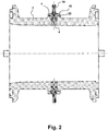
- Fig. 2 shows a non-inventive embodiment of an electrode.
- An electrode 1 has a casing 18 made of plastic, which is inserted into the measuring tube wall 2. This jacket 18 is made, for example, from the same plastic as the measuring tube wall 2.
- the electrode 1 is cast into the jacket 18, wherein the surface of the electrode 1 is at least partially covered with a plastic. At least a free portion of the surface of the electrode 1 is not covered with the plastic, here the electrode head 4 and the opposite end of the electrode 1 with a bore along the longitudinal axis of the electrode 1, in which here a plug 19 for electrical contacting of the electrode. 1 is introduced.
- the potential picked up by the electrodes is transmitted to a measuring and / or operating circuit - not explicitly shown. From the electrical potential, a voltage proportional to the flow rate is derived and from this the flow rate is determined.
- the jacket 18 together with the electrode 1 can be produced separately from the measuring tube, or in a method in a subsequent method step.
- a measuring tube is first manufactured with a space provided for the installation of the electrode with sheath, this space is kept free by a core or a tool. This core is then removed. Thereafter, the electrode 1 can be used together with sheath 18 or only the electrode 1 is used and filled the free space with liquefied plastic. This has the advantage of not having to weld the sheath extra to the measuring tube.
- an electrode can also be produced in a dipping bath, wherein liquefied plastic settles on the electrode and is subsequently machined mechanically to the desired shape.
- Next Coating process however, such processes are more expensive than the described injection molding.
- the sheath 18 forms part of the measuring tube wall 2. At least the part of the measuring tube wall 2 which surrounds and touches the electrode 1 is made of plastic. Now there are other alternatives to a sheath 18 to an electrode 1, which is used in a finished measuring tube and an electrode 1, around which the complete measuring tube is poured.
- the measuring tube wall 2 can have a free space into which the electrode 1 is inserted and which is subsequently filled with plastic, on the other hand, around the electrode 1 only a part of the measuring tube, e.g. a half-shell are then poured, wherein the half-shells subsequently combined to form a measuring tube, e.g. be welded together. Clear manufacturing advantages of the half-shells are obvious to the expert.
- a measuring tube has further components, such as e.g. Flanges. These may or may not be produced in a single process. In particular, flanges can be easily attached to a measuring tube.
- Fig. 3 is a non-inventive electrode 1 together with their, separately produced to the measuring tube casing 18 in section.
- the electrode 1 has a bore 10 for receiving a plug and a plurality of sawtooth-shaped recesses.
- An elastic sealing ring is not provided. Tightness of the connection jacket 18 and electrode 1 is achieved by the plurality of punctures.
- a collar 8 projects perpendicularly from the electrode longitudinal axis 9 in the region of the end of the electrode shaft, opposite the electrode head, for fixing the electrode 1 in the tool and / or the connection with the plastic of the sheath 18.
- the plastic of the casing 18 has similar properties as the plastic of the measuring tube wall, or is even the same.
- the sheath 18 is configured disc-shaped in the region of the collar-shaped collar 8 of the electrode 1.
- This disc 20 of the casing is in the mounted state on a on the Outside of the measuring tube arranged bearing surface is present.
- the support surface is formed by a holder 22.
- the introduced into the measuring tube cylindrical bore is surrounded by the holder 22 in the form of a collar-like approach.
- the holder 22 is located on the outside of the measuring tube.
- the measuring tube consists at least in the region of the bore and the holder 22 made of plastic.
- the casing 18 together with the embedded electrode rests with its disk 20 on the flat support surface which terminates the holder.
- the bearing surface of the disc 20 extends perpendicular to the electrode longitudinal axis and parallel to the longitudinal axis of the measuring tube.
- the disc 20 is connected to the bracket 22 by a plastic welding process.
- the disc additionally has a welding lip 21 along the joining zone on the holder 22.
- the welding lip 21 has a roof-shaped cross section and is fused cohesively to the holder 22. As a result, the bore is sealed pressure and liquid-tight.
- Fig. 4 are sketched various non-inventive electrodes.
- the electrodes in this case have the same basic shape, but differ by their punctures 11.
- Punctooth shape described above
- semicircular recesses 11 and rectangular grooves 11 can be seen.
- other forms for anchoring the electrode and extending the leakage paths are possible, for example, with undercut.
- a sawtooth-shaped groove 7 The groove 7 is bounded by the tooth back 13 and the tooth face 14.
- the free space in between is referred to as a tooth gap 15.
- the point of intersection between tooth back 13 and tooth face 14 of a single sawtooth-shaped recess 7 is called tooth base 16, the point of intersection between tooth back 13 and tooth face 14 of FIG two adjacent sawtooth-shaped recesses 7 is called tooth tip 17th wedge angle we called the angle between the tooth back 13 and tooth face 14.
Landscapes
- Physics & Mathematics (AREA)
- Electromagnetism (AREA)
- Fluid Mechanics (AREA)
- General Physics & Mathematics (AREA)
- Measuring Volume Flow (AREA)
Description
- Die vorliegende Erfindung betrifft ein Verfahren zur Herstellung eines magnetisch-induktiven Durchflussmessgeräts durch Umgießen einer länglichen Elektrode mit verflüssigtem Kunststoff und ein magnetisch-induktives Durchflussmessgerät herstellbar nach dem erfindungsgemäßen Verfahren.
- Magnetisch-induktive Durchflussmessgeräte nutzen für die volumetrische Strömungsmessung das Prinzip der elektrodynamischen Induktion aus und sind aus einer Vielzahl von Veröffentlichungen bekannt. Senkrecht zu einem Magnetfeld bewegte Ladungsträger des Mediums induzieren eine Messspannung in im Wesentlichen senkrecht zur Durchflussrichtung des Mediums und senkrecht zur Richtung des Magnetfeldes angeordneten Messelektroden. Die in die Messelektroden induzierte Messspannung ist proportional zu der über den Querschnitt des Messrohres gemittelten Strömungsgeschwindigkeit des Mediums, also proportional zum Volumenstrom. Ist die Dichte des Mediums bekannt, lässt sich der Massestrom in der Rohrleitung bzw. in dem Messrohr bestimmen. Die Messspannung wird üblicherweise über ein Messelektrodenpaar abgegriffen, das bezüglich der Koordinate entlang der Messrohrachse in dem Bereich maximaler Magnetfeldstärke angeordnet ist und wo folglich die maximale Messspannung zu erwarten ist. Die Elektroden sind üblicherweise galvanisch mit dem Medium gekoppelt; es sind jedoch auch magnetisch-induktive Durchflussmessgeräte mit berührungslos kapazitiv koppelnden Elektroden bekannt.
- Das Messrohr kann dabei entweder aus einem elektrisch leitfähigen, nichtmagnetischen Material, z.B. Edelstahl, gefertigt sein, oder aus einem elektrisch isolierenden Material bestehen. Ist das Messrohr aus einem elektrisch leitfähigen Material gefertigt, so muss es in dem mit dem Medium in Kontakt kommenden Bereich mit einem Liner aus einem elektrisch isolierenden Material ausgekleidet sein. Der Liner besteht je nach Temperatur und Medium beispielsweise aus einem thermoplastischen, einem duroplastischen oder einem elastomeren Kunststoff. Es sind jedoch auch magnetisch-induktive Durchflussmessgeräte mit einer keramischen Auskleidung bekannt.
- Eine Elektrode lässt sich im Wesentlichen in einen Elektrodenkopf, der zumindest teilweise mit einem Medium, welches das Messrohr durchströmt, in Kontakt kommt, und einen Elektrodenschaft, der fast vollständig in der Wandung des Messrohres eingebracht ist, unterteilen.
- Die Elektroden sind neben dem Magnetsystem die zentralen Komponenten eines magnetisch-induktiven Durchflussmessgerätes. Bei der Ausgestaltung und Anordnung der Elektroden ist darauf zu achten, dass sie sich möglichst einfach in dem Messrohr montieren lassen und dass nachfolgend im Messbetrieb keine Dichtigkeitsprobleme auftreten; darüber hinaus sollen sich die Elektroden durch eine empfindliche und gleichzeitig störungsarme Messsignalerfassung auszeichnen.
- Neben den Messelektroden, die zum Abgriff eines Messsignals dienen, werden oftmals zusätzliche Elektroden in Form von Bezugs- oder Erdungselektroden in das Messrohr eingebaut, die dazu dienen, ein elektrisches Referenzpotential zu messen oder teilgefüllte Messrohre zu erkennen.
- Die Elektroden weisen meist längliche Elektrodenschäfte auf, mit divers geformten Einkerbungen. Die
WO 2009/071615 A2 zeigt eine Elektrode mit einem Elektrodenschaft, mit mehreren kegelstumpfförmigen Dichtlippen, wobei die Durchmesser der Dichtlippen in ihrer Größe variieren. Gleichwertig sind Elektroden mit sägezahnförmigen Einstichen, wobei die Durchmesser der Elektrode an den Zahnspitzen der sägezahnförmigen Einstiche in ihrer Größe variieren. - In der
DE 10 2008 038 161 undDE 10 2008 038 162 sind Elektroden zusammen mit anderen Bauteilen eines magnetisch-induktiven Durchflussmessgeräts mit dem Messrohr in einem separaten bzw. in einem gemeinsamen Kunststoffverguss eingegossen. - Die
WO 10015534 A1 - Die Fig. 5A der Druckschrift
DE 10 2007 004 826 A1 zeigt eine Detailansicht einer mehrteiligen Messelektrode eines Durchflussmessgerätes, bei welcher ein erstes Messelektrodenteil 26 in einer Messrohrwandung 2 eingebettet ist. Man erkennt an der Stelle 28 eine einstichartige Ausformung. Man erkennt zudem aus Fig. 5A, dass die Messrohrwandung in diese Ausformung hineinragt.
Die DruckschriftWO 2010/015534 A1 offenbart ein Durchflussmessgerät, bei welchem eine Festlegung einer Messelektrode mittels einer Kunststoff-Schweißtechnik erfolgt. Die Messelektrode weist eine vorgeformte Ausnehmung 13 und einen O-Dichtring auf, welcher lose in der Ausformung angeordnet ist.
Die DruckschriftWO 2008/059020 A1 offenbart eine Messelektrode, welche eine Tannenbaumstruktur aufweist. Hier sorgen seitlich aus dem Elektrodenkörper hervorstehende Widerhaken und die Pilzkopfstruktur der Elektrode für eine bessere Dichtwirkung. - Die Aufgabe der Erfindung besteht darin, ein magnetisch-induktives Messgerät bereit zu stellen mit einer kostengünstig herzustellenden und hochwirksam dichtenden Elektrodenanordnung.
- Die Aufgabe wird gelöst durch den Gegenstand des Anspruchs 1. Weiterbildungen und Ausgestaltungen der Erfindungen finden sich in den Merkmalen der abhängigen Ansprüche wider.
- So wird ein Magnetisch-induktives Durchflussmessgeräts zum Messen des Volumen- oder Massestroms eines Mediums in einer Rohrleitung, mit einem Messrohr, das das Medium in Richtung der Längsachse des Messrohres durchströmt, mit einem Magnetsystem, das derart ausgestaltet ist, dass es ein das Messrohr durchsetzendes, im wesentlichen quer zur Längsachse des Messrohrs verlaufendes Magnetfeld erzeugt, mit zumindest einer mit dem Medium koppelnden Messelektrode, die in einem im wesentlichen senkrecht zum Magnetfeld liegenden Bereich in einer Bohrung in der Wand des Messrohres angeordnet ist, mit einem erfindungsgemäßen Verfahren hergestellt, welches folgende Verfahrensschritte umfasst:
- Herstellen einer länglichen Elektrode mit zumindest einem ersten, quer zur Längsausdehnung der Elektrode umfänglich umlaufenden Einstich aus einem elektrisch leitfähigen Material;
- Positionieren der Elektrode in einem Werkzeug;
- zumindest abschnittsweise Umgießen der Elektrode mit Kunststoff, wobei der erste Einstich zur Aufnahme des Dichtrings vorgesehen und ausgestaltet ist, wobei der Dichtring vor Umgießen mit verflüssigtem Kunststoff positioniert wird, wobei der Dichtring aus einem Polymer hergestellt wird und dass die Temperatur des Kunststoffs während des zumindest abschnittsweisen Umgießens des Dichtrings unterhalb 350°C gehalten wird.
- Insbesondere findet ein Spritzgussverfahren Anwendung, wobei der Kunststoff verflüssigt und damit die Elektrode umspritzt wird. Die längliche Elektrode weist zumindest eine Längsausdehnung längs einer Längsachse auf, welche größer ist, als eine Querausdehnung der Elektrode, senkrecht zur die Längsachse. Insbesondere ist das Verhältnis von Längsausdehnung zu Querausdehnung größer 2. Die Elektrode kann zuerst vollständig mit Kunststoff ummantelt sein, bevor der überschüssige Kunststoff wieder entfernt wird. Bevorzugt wird jedoch ein Ummanteln der Elektrode mit Kunststoff, wobei zumindest der Elektrodenkopf nicht von Kunststoff bedeckt ist. Weiterhin ist am, dem Elektrodenkopf gegenüberliegenden, Schaftende der Elektrode ebenfalls kein Kunststoff vorgesehen, um die Elektrode elektrisch zu kontaktieren. Die längliche Elektrode ist in einer Weiterbildung der Erfindung im betriebsbereiten magnetisch-induktiven Durchflussmessgerät mit ihrer Längsachse senkrecht zur Messrohrachse in der Messrohrwand positioniert.
- Die Elektrode wird mit einem umfänglich umlaufenden Einstich hergestellt, beispielsweise aus Edelstahl, oder aber auch aus einem elektrisch leitfähigen Kunststoff. Weist die Elektrode einen kreisförmigen Querschnitt quer zur Längsachse der Elektrode auf, ist der Einstich radial umlaufend. Ist der Einstich im Querschnitt rechteckförmig, kann dann von einer Ringnut gesprochen werden. In anderen Ausgestaltungen der Elektrode können die Querschnitte elliptisch, oval oder mehreckig sein. Die Einstiche können ebenfalls verschiedenartige Querschnittsformen aufweisen, z.B. rechteckige oder halbkreisförmige oder sägezahnförmige.
- Wird ein elastischer Dichtring an der Elektrode positioniert, wird er auf die Elektrodenoberfläche dichtend aufgebracht, z.B. auf den Mantel einer zylindrisch geformten Elektrode gespannt, wobei der Dichtring, in diesem Beispiel ein so genannter O-Ring, dann einen inneren, freien Durchmesser aufweist, geringer als der Durchmesser des Mantels der Elektrode an der Position des Dichtrings auf der Elektrode. Der Dichtring wird insbesondere an der Elektrode positioniert, bevor die Elektrode in dem Werkzeug positioniert wird; jedenfalls aber bevor die Elektrode mit verflüssigtem Kunststoff umgossen wird. In einem Ausführungsbeispiel wird der Dichtring in einem Einstich der Elektrode positioniert, welcher zur Aufnahme des Dichtrings vorgesehen und entsprechend ausgestaltet ist. Form und Größe des Dichtrings und des ersten Einstichs sind aufeinander abgestimmt; beispielsweise zueinander komplementär.
- Während die Elektrode mit Kunststoff umgossen wird, wird der elastische Dichtring zumindest abschnittsweise mit Kunststoff bedeckt. Dabei wird die Temperatur des Kunststoffs unterhalb 350°C, insbesondere unterhalb 200°C gehalten. Verarbeitung und Material des Kunststoffs und Material des Dichtrings sind ebenfalls aufeinander abgestimmt. Der Dichtring besteht beispielsweise aus EPDM, Viton oder Kalrez.
- Es versteht sich von selbst, dass der Dichtring sowohl gegenüber dem die Elektrode umgebenden Kunststoff, als auch gegenüber der Elektrode selbst fluiddicht dichtet. Weitere Einstiche können in der Elektrodenoberfläche vorgesehen sein, zur axialen Fixierung oder Bestimmung der Elektrode oder zur Leckagewegverlängerung. Diese haben ebenfalls rechteckige oder halbkreisförmige oder sägezahnförmige Querschnitte. Mindestens einer dieser weiteren Querschnitte wird, falls vorhanden, zumindest teilweise mit Kunststoff bei der Herstellung ausgefüllt.
- Weist eine Elektrode, welche im betriebsbereiten magnetisch-induktiven Durchflussmessgerät so positioniert ist, dass ihre Längsachse senkrecht auf der Messrohrachse steht, mehrere, am Umfang der Elektrode senkrecht zur Längsachse der Elektrode umlaufenden Einstiche mit einem sägezahnförmigen Querschnitt auf, ist gemäß einer Ausgestaltung die Ausrichtung der Sägezähne so, dass die jeweiligen Zahnrücken von ihrem Zahngrund bis zu ihrer Zahnspitze in Richtung des strömungsführenden Lumes des Messrohrs zeigt, also eine Richtungskomponente in Richtung der Messrohrachse weist. Die Zahnlücken sind dabei zumindest abschnittsweise mit Kunststoff ausgegossen.
- Auch eine so genannte Tannenbaumform, wie in der
WO 2009/071615 A2 offenbart, wobei hier die Sägezähne unterschiedlich lange Zahnrücken oder unterschiedliche Keilwinkel aufweisen, so dass die Abstände der Zahnspitzen zur Längsachse der Elektrode verschieden sind, sind hiermit umfasst.
Ein Einstich wird aus fertigungstechnischen Gründen als solcher bezeichnet. Ein Einstich bildet eine Ausnehmung, z.B. in einem Drehteil. Natürlich verursacht ein einzelner Einstich, geometrisch gesehen, zwei neben dem Einstich liegende Ausformungen. So weist in einem Beispiel eine erfindungsgemäße Elektrode einen kragenförmigen Bund auf. Ein anderes Beispiel zeigt eine erfindungsgemäße Elektrode mit radial umlaufenden Ausformungen zur Verankerung der Elektrode und zur Verlängerung der Leckagewege. In beiden Beispiele können die Ausformungen auch dadurch erhalten werden, dass Ausnehmungen neben den Ausformungen vorgenommen werden, welche die Ausformungen erst als solche erscheinen lassen. - Ausgerichtet wird die Elektrode im Werkzeug beispielsweise mittels einer ersten und zweiten Kontur. So weist die Elektrode z.B. einen konischen Elektrodenkopf und/oder eine Bohrung im gegenüberliegenden Schaftende auf. Das Werkzeug oder ein das Lumen des Messrohrs formender Kern weisen die komplementären und zu den Konturen der Elektrode kompatiblen, d.h. mit den Konturen der Elektrode miteinander vereinbaren Konturen auf. Die Elektrode wird so z.B. mit ihrem konischen Elektrodenkopf auf eine komplementäre konische Senkung im Kern für das, im späteren Betrieb des magnetisch-induktiven Durchflussmessgeräts strömungsführenden, Lumen des Messrohrs angesetzt und somit formschlüssig mit dem Kern verbunden. Alternativ kann die Elektrode auch eine Nut statt einer Bohrung im, dem Elektrodenkopf gegenüberliegenden Ende des Elektrodenschafts aufweisen, oder auch per Magnetismus im Werkzeug ausgerichtet und während des Gießvorgangs gehaltert werden.
- In einem Ausführungsbeispiel wird die Elektrode mit Kunststoff umgossen, welcher gleichzeitig das Messrohr bildet. In einer anderen Ausgestaltung wird in einem ersten Verfahrensschritt das Messrohr mit einem für die Positionierung der Elektrode vorgesehenen Raum gegossen und anschließend die Elektrode in diesen Raum eingesetzt und mit Kunststoff umgossen, wobei das vorgefertigte Messrohr hier als Werkzeug dient, und die Ummantelung der Elektrode mit Kunststoff, welche im zweiten Verfahrensschritt hergestellt wird, ebenfalls Teil des Messrohrs ist. Weitere Ausgestaltungen zeigen die Elektrode ummantelt von Kunststoff, wobei die Elektrode mitsamt dem Mantel in eine Bohrung in der Messrohrwand eingesetzt wird und beispielsweise mit dieser anschließend verschweißt wird, insbesondere mit Ultraschallschweißen.
- Wird mit dem verflüssigten Kunststoff zumindest ein Teil des Messrohrs, insbesondere eine Halbschale, gegossen und wird ein Kern, welcher ein Lumen des Messrohrs formt, und eine zu einer zweiten Kontur der Elektrode komplementäre vierte Kontur aufweist, wobei die Elektrode an dem Kern durch formschlüssiges Ausrichten der zweiten und vierten komplementären Kontur zueinander positioniert wird, werden diese Teile des Messrohrs, z.B. zwei baugleiche Halbschalen, mit anderen Teilen anschließend miteinander verbunden, insbesondere miteinander stoffschlüssig verschweißt.
- Die Erfindung lässt zahlreiche Ausführungsformen zu. Einige davon sollen hier kurz anhand der nachfolgenden Figuren näher erläutert werden. Gleiche Elemente sind in den Figuren mit gleichen Bezugszeichen versehen.
- Fig. 1
- zeigt den Querschnitt durch ein Messrohr und eine Elektrode eines erfindungsgemäßen magnetisch-induktiven Durchflussmessgeräts in einer ersten Ausgestaltung,
- Fig. 2
- zeigt den Querschnitt durch ein Messrohr und eine nicht erfindungsgemäße Elektrode eines beispielhaften magnetisch-induktiven Durchflussmessgeräts,
- Fig. 3
- zeigt den Querschnitt durch eine nicht erfindungsgemäße Elektrode eines magnetisch-induktiven Durchflussmessgeräts mit einer Ummantelung aus Kunststoff,
- Fig. 4
- zeigt mehrere Querschnitte durch unterschiedliche nicht erfindungsgemäße Elektrodenformen.
- Die vorliegende Erfindung betrifft ein Verfahren zur Herstellung eines magnetisch-induktiven Durchflussmessgeräts, insbesondere der Prozessmesstechnik, zur Ermittlung des Durchflusses eines Messmediums durch ein Messrohr.
- In
Fig. 1 ist nun ein Querschnitt durch eine Elektrodenanordnung eines magnetisch-induktiven Durchflussmessgerätes dargestellt. Die Elektrode 1 ist in die Wand 2 eines Messohrs eingebracht und weist einen Elektrodenschaft 3 und einen im Messbetrieb vom Messstoff 5 wenigstens teilweise benetzten Elektrodenkopf 4 auf. Messstoffe 5 können sowohl Reinstoffe als auch Gemische sein. Der Elektrodenkopf 4 weist, in dem Bereich in dem er in das Lumen des Messrohrs hineinragt, eine konische Form auf. Im Bereich der Messrohrwand 2 weist der Elektrodenschaft 3 eine zylindrische Grundform auf. Ein Querschnitt durch die Elektrode 1 in einer parallelen Ebene zum O-Ring 6 ist näherungsweise kreisrund, im Rahmen der üblichen und einem Fachmann geläufigen konstruktiven und fertigungsbedingten Toleranzen. Auch andere Formen sind möglich. Ovale oder elliptische Querschnitte versprechen eine bessere Spannungsverteilung bei Wärmeausdehnung des Messrohrs. - Darüber hinaus ist im Bereich des Elektrodenschafts 3 ein erster radialer Einstich 7 vorgesehen, in welchem ein Dichtring, hier der O-Ring 6 positioniert ist. Der O-Ring 6 ragt geringfügig über den Rand des Elektrodenschafts 3 hinaus, so dass er eine erste Dichtstufe bildet und die Elektrode 1 im Bereich der Messrohrwand 2 abdichtet. An dem vom Elektrodenkopf 4 abgewandten Ende weist die Elektrode einen Bund 8 auf, mit dem die Elektrode 1 abschließt. Der Bund 8 steht senkrecht von der Elektrodenlängsachse 9 ab. Entlang der Elektrodenlängsachse 9 weist die Elektrode 1 in dem vom Elektrodenkopf 4 abgewandeten Ende eine Bohrung 10 auf, in die ein nicht dargestellter Stecker einbringbar ist. Der Stecker dient dabei zum Abgreifen des mittels des Elektrodenkopfs 4 im Messstoff 5 gemessen elektrischen Potentials. Die Bohrung 10 dient weiterhin während des Herstellungsverfahrens als zweite Kontur zur Ausrichtung der Elektrode im Werkzeug. In diesem Sinn als erste Kontur dient der konisch ausgeformte Elektrodenkopf 4.
- Im Herstellungsverfahren zu dieser Ausgestaltung der Erfindung wird also beispielsweise die Elektrode 1 in ein Spritzgusswerkzeug eingelegt. Dafür wird der Elektrodenkopf 4 in einer zum Elektrodenkopf 4 komplementären Ausformung in einem Kern positioniert. Der Kern bildet später das Lumen des Messrohrs, in welchem der Messstoff 5 strömt. Weiterhin wird die Elektrode 1 mittels eines Dorns in der Bohrung 10 im Elektrodenschaft 3 fixiert, bevor die Elektrode mit Kunststoff umspritzt wird. In diesem Beispiel wird die Elektrode 1 direkt in die Messrohrwand 2, welche hier aus einem Guss hergestellt wird, eingegossen. In anderen Beispielen wird die Messrohrwand 2 in zwei oder mehr Güssen hergestellt.
- Das Messrohr ist wenigstens im Bereich der Elektroden von einem Gehäuse, welches hier nicht gezeigt ist, umgeben. Das vom Messstoff 5 durchflossene, unter einem Prozessdruck stehende Messrohr wird im Bereich des Elektrodenschafts 3 durch eine erste Dichtungsstufe, bestehend aus einem radial angeordneten O-Ring 6, druck- und flüssigkeitsdicht verschlossen. Der O-Ring 6 weist die erforderlichen physikalischen und chemischen Eigenschaften auf, die für den Gebrauch in typischen Messstoffen wie z.B. Trink- und Abwasser notwendig sind. Weiterhin ist der O-Ring 6 speziell für einen Einsatz in Verbindung mit aus Kunststoff bestehenden Materialien ausgelegt. Typische Materialen für erfindungsgemäße Messrohre sind z.B. PA, PP, PPE, PSU, PPS, PEEK oder PVC. Die Elektroden sind z.B. aus nichtrostenden Edelstählen, Tantal, Hastelloy, Platin oder Titan gefertigt.
- Der O-Ring 6 wir in diesem Beispiel vom Kunststoff der Messrohrwand 2 abschnittsweise umschlossen. An den Abschnitten, wo der O-Ring 6 auf der Elektrode 1 selbst aufliegt, ist er natürlich nicht von Kunststoff bedeckt. Der erste Einstich 7 wird hier ebenfalls vom Kunststoff der Messrohrwand 2 teilweise ausgefüllt. Der O-Ring 6 wird auf der Elektrode 7, hier im Einstich 7, positioniert, bevor die Elektrode 1 im Werkzeug positioniert wird.
- Neben dem ersten Einstich 7, in welchem der O-Ring 6 positioniert ist, weist die Elektrode weitere Einstiche 11 auf, welche mit dem Kunststoff der Messrohrwand 2 ausgegossen sind. Durch sie werden Ausformungen 12 der Elektrode 1 definiert, welche zur axialen Verankerung der Elektrode 1 entlang der Längsachse 9 in der Messrohrwand 2 dienen und welche gleichzeitig die Leckagewege verlängern. Hier wiesen die Einstiche 7 und 11 rechteckige Form im Querschnitt auf, jedoch sind viele Formen denkbar, so z.B. auch mit Hinterschnitt oder halbkreisförmig zur Aufnahme eines O-Rings 6 mit kreisförmigem Schnurquerschnitt.
- Der erste Einstich 7 weist eine Tiefe senkrecht zur Längsachse 9 der Elektrode 1 auf und eine Breite parallel zur Längsachse 9 der Elektrode 1. Auch der Dichtungsring, hier O-Ring 6, weist eine Schnurdicke in Richtung der Längsachse 9 und eine Schnurbreite senkrecht zur Längsachse 9 der Elektrode 1 auf. Ist der Dichtungsring, wie in dieser Figur veranschaulicht, ein O-Ring 6, so ist die Schnurdicke und die Schnurbreite gleich und entspricht dem Schnurdurchmesser von. Das Verhältnis von Schnurdicke zur Einstichsbreite liegt gemäß einer Ausgestaltung bei höchstens 0,8 und bei mindestens 0,6, wobei dann das Verhältnis von Schnurbreite zu Einstichstiefe höchstens 1,5 und mindestens 1,2 beträgt. Ist der Dichtungsring ein O-Ring 6 ist die freie Fläche durch den Innendurchmesser des O-Rings 6 definiert. Der Dichtungsring wird somit dichtend auf die Elektrode gespannt.
-
Fig. 2 zeigt eine nicht erfindungsgemäße Ausgestaltung einer Elektrode. Eine Elektrode 1 weist eine Ummantelung 18 aus Kunststoff auf, welche in die Messrohrwand 2 eingesetzt ist. Diese Ummantelung 18 ist beispielsweise aus demselben Kunststoff hergestellt, wie die Messrohrwand 2. Die Elektrode 1 ist in die Ummantelung 18 eingegossen, wobei die Oberfläche der Elektrode 1 zumindest abschnittsweise mit einem Kunststoff bedeckt ist. Zumindest ein freier Abschnitt der Oberfläche der Elektrode 1 ist nicht mit dem Kunststoff bedeckt, hier der Elektrodenkopf 4 und das ihm gegenüberliegende Ende der Elektrode 1 mit einer Bohrung längs der Längsachse der Elektrode 1, in welcher hier ein Stecker 19 zur elektrischen Kontaktierung der Elektrode 1 eingeführt ist. Das von den Elektroden abgegriffene Potential wird an eine Mess- und/oder Betriebsschaltung - nicht explizit gezeigt - übermittelt. Aus dem elektrischen Potential wird eine dem Durchfluss proportionale Spannung abgeleitet und daraus der Durchfluss bestimmt. - Die Ummantelung 18 mitsamt der Elektrode 1 kann separat zum Messrohr hergestellt werden, oder in einem Verfahren in einem nachfolgenden Verfahrensschritt.
- Wird zuerst ein Messrohr mit einem für den Einbau der Elektrode mit Ummantelung vorgesehenen Raum gefertigt, wird dieser Raum von einem Kern oder einem Werkzeug frei gehalten. Dieser Kern wird anschließend entfernt. Danach kann die Elektrode 1 mitsamt Ummantelung 18 eingesetzt werden oder nur die Elektrode 1 wird eingesetzt und der freie Raum mit verflüssigtem Kunststoff ausgefüllt. Dies hat den Vorteil, die Ummantelung nicht extra am Messrohr anschweißen zu müssen.
- Natürlich sind neben dem beschriebenen Spritzgussverfahren auch andere Urformverfahren mit umfasst. So lässt sich eine Elektrode auch in einem Tauchbad herstellen, wobei sich verflüssigter Kunststoff auf der Elektrode festsetzt und anschließend mechanisch bis zur gewünschten Form bearbeitet wird. Neben Beschichtungsverfahren sind solche Verfahren jedoch aufwendiger als das beschriebene Spritzgießen.
- Die Ummantelung 18 bildet einen Teil der Messrohrwand 2. Zumindest der die Elektrode 1 umgebende und berührende Teil der Messrohrwand 2 ist aus Kunststoff hergestellt. Nun bestehen weitere Alternativen zu einer Ummantelung 18 um eine Elektrode 1, welche in ein fertiges Messrohr eingesetzt wird und einer Elektrode 1, um welche das komplette Messrohr gegossen wird. So kann einerseits die Messrohrwand 2 einen Freiraum aufweisen, in welchen die Elektrode 1 eingesetzt und welcher anschließend mit Kunststoff ausgegossen wird, andererseits kann um die Elektrode 1 nur ein Teil des Messrohrs, z.B. eine Halbschale gegossen werden, wobei die Halbschalen anschließend zu einem Messrohr vereint, z.B. miteinander verschweißt werden. Eindeutige fertigungstechnische Vorteile der Halbschalen liegen dem Fachmann auf der Hand. Neben dem eigentlichen strömungsführenden Teil des Messrohrs weist ein Messrohr weitere Bauteile auf, wie z.B. Flansche. Diese können, müssen aber natürlich nicht in einem einzigen Verfahren hergestellt werden. Insbesondere Flansche lassen sich einfach an ein Messrohr anbringen.
- In
Fig. 3 ist eine nicht erfindungsgemäße Elektrode 1 mitsamt ihrer, zum Messrohr separat hergestellter Ummantelung 18 im Schnitt gezeichnet. Die Elektrode 1 weist eine Bohrung 10 zur Aufnahme eines Steckers und mehrere sägezahnförmige Einstiche auf. Ein elastischer Dichtungsring ist nicht vorgesehen. Dichtheit der Verbindung Ummantelung 18 und Elektrode 1 wird durch die Vielzahl an Einstichen erreicht. Ein Bund 8 steht senkrecht von der Elektrodenlängsachse 9 im Bereich des Ende des Elektrodenschafts ab, gegenüber dem Elektrodenkopf, zur Fixierung der Elektrode 1 im Werkzeug und/oder der Verbindung mit dem Kunststoff der Ummantelung 18. - Der Kunststoff der Ummantelung 18 weist gleichartige Eigenschaften wie der Kunststoff der Messrohrwand auf, oder ist gar gleich. Die Ummantelung 18 ist im Bereich des kragenförmigen Bunds 8 der Elektrode 1 scheibenförmig ausgestaltet. Diese Scheibe 20 der Ummantelung liegt im montierten Zustand auf einer auf der Außenseite des Messrohrs angeordneten Auflagefläche anliegt. Die Auflagefläche wird geformt durch eine Halterung 22.
- Die in das Messrohr eingebrachte zylindrische Bohrung ist von der Halterung 22 in Form eines kragenartigen Ansatzes umgeben. Die Halterung 22 befindet sich auf der Außenseite des Messrohrs. Das Messrohr besteht dabei wenigstens im Bereich der Bohrung und der Halterung 22 aus Kunststoff. Die Ummantelung 18 mitsamt eingebetteter Elektrode liegt mit ihrer Scheibe 20 auf der ebenen die Halterung abschließenden Auflagefläche auf. Die Auflagefläche der Scheibe 20 verläuft senkrecht zur Elektrodenlängsachse und parallel zur Längsachse des Messrohrs. Die Scheibe 20 ist durch ein Kunststoff-Schweißverfahren mit der Halterung 22 verbunden.
- Die Scheibe weist zusätzlich entlang der Fügezone auf der Halterung 22 eine Schweißlippe 21 auf. Die Schweißlippe 21 hat einen dachförmigen Querschnitt und wird mit der Halterung 22 stoffschlüssig verschmolzen. Dadurch ist die Bohrung druck- und flüssigkeitsdicht abgedichtet.
- Zu den Bezeichnungen an einem sägezahnförmigen Einstich siehe die nachfolgende Beschreibung zur
Fig. 4 . - In
Fig. 4 sind verschiedenartige nicht erfindungsgemäße Elektroden skizziert. Die Elektroden weisen hierbei die gleiche Grundform auf, unterscheiden sich jedoch durch ihre Einstiche 11. Neben der bereits beschriebenen Sägezahnform sind noch halbkreisförmige Einstiche 11 und rechteckförmige Einstiche 11 zu sehen. Aber auch andere Formen zur Verankerung der Elektrode und zur Verlängerung der Leckagewege sind möglich, z.B. auch mit Hinterschnitt. - Hier noch kurz zu den Bezeichnungen an einem sägezahnförmigen Einstich 7. Der Einstich 7 wird durch den Zahnrücken 13 und die Zahnbrust 14 begrenzt. Der freie Raum dazwischen wird als Zahnlücke 15 bezeichnet. Der Schnittpunkt zwischen Zahnrücken 13 und Zahnbrust 14 eines einzigen sägezahnförmigen Einstichs 7 heißt Zahngrund 16, Der Schnittpunkt zwischen Zahnrücken 13 und Zahnbrust 14 von zwei benachbarten sägezahnförmigen Einstichen 7 heißt Zahnspitze 17. Keilwinkel wir der Winkel zwischen Zahnrücken 13 und Zahnbrust 14 genannt.
-
- 1
- Elektrode
- 2
- Messrohrwand
- 3
- Elektrodenschaft
- 4
- Elektrodenkopf
- 5
- Messstoff
- 6
- Dichtungsring
- 7
- Erster Einstich
- 8
- Bund
- 9
- Elektrodenfängsachse
- 10
- Bohrung im Elektrodenschaft
- 11
- Zweite Einstiche
- 12
- Ausformungen am Elektrodenschaft
- 13
- Zahnrücken eines Sägezahns
- 14
- Zahnbrust eines Sägezahns
- 15
- Zahnlücke eines Sägezahns
- 16
- Zahngrund eines Sägezahns
- 17
- Zahnspitze eines Sägezahns
- 18
- Ummantelung
- 19
- Stecker
- 20
- Scheibe
- 21
- Schweißlippe
- 22
- Halterung
Claims (10)
- Verfahren zur Herstellung eines magnetisch-induktiven Durchflussmessgeräts durch Umgießen einer Elektrode (1) mit verflüssigtem Kunststoff,
wobei die Elektrode aus einem elektrisch leitfähigen Material und mit zumindest einem ersten, senkrecht zu einer Längsausdehnung der Elektrode (1) umfänglich umlaufenden Einstich (1) hergestellt wird,
wobei die Elektrode (1) in einem Werkzeug positioniert wird und zumindest abschnittsweise mit verflüssigtem Kunststoff umgossen wird,
wobei der erste Einstich (7) der Elektrode (1) zumindest abschnittsweise mit verflüssigtem Kunststoff umgossen wird,
dadurch gekennzeichnet, dass
ein elastischer Dichtring (6) in dem ersten Einstich (7) der Elektrode (1) zur Aufnahme des Dichtrings (6) positioniert wird, wobei der elastische Dichtring (6) zumindest abschnittsweise mit Kunststoff umgossen wird,
wobei der erste Einstich zur Aufnahme des Dichtrings vorgesehen und ausgestaltet ist,
wobei der Dichtring vor Umgießen mit verflüssigtem Kunststoff positioniert wird, wobei der Dichtring (6) aus einem Polymer hergestellt wird und wobei die Temperatur des Kunststoffs während des zumindest abschnittsweisen Umgießens des Dichtrings (6) unterhalb 350°C gehalten wird. - Verfahren zur Herstellung eines magnetisch-induktiven
Durchflussmessgeräts nach Anspruch 1,
dadurch gekennzeichnet,
dass die Elektrode (1) mit einem kreisrunden oder elliptischen oder ovalen Querschnitt hergestellt wird. - Verfahren zur Herstellung eines magnetisch-induktiven
Durchflussmessgeräts nach einem der Ansprüche 1 bis 2,
dadurch gekennzeichnet,
dass die Elektrode (1) mit weiteren Einstichen (11) hergestellt wird, welche zumindest abschnittsweise mit verflüssigtem Kunststoff ausgegossen werden. - Verfahren zur Herstellung eines magnetisch-induktiven
Durchflussmessgeräts nach einem der Ansprüche 1 bis 4,
dadurch gekennzeichnet,
dass das Werkzeug eine zu einer ersten Kontur der Elektrode (1) komplementäre dritte Kontur aufweist und dass das Positionieren der Elektrode (1) in dem Werkzeug durch formschlüssiges Ausrichten der komplementären ersten und dritten Kontur zueinander erfolgt. - Verfahren zur Herstellung eines magnetisch-induktiven Durchflussmessgeräts nach einem der Ansprüche 1 bis 4,
dadurch gekennzeichnet,
dass mit dem verflüssigten Kunststoff ein Messrohr gegossen wird und dass ein Kern, welcher ein Lumen des Messrohrs formt, eine zu einer zweiten Kontur der Elektrode (1) komplementäre vierte Kontur aufweist, wobei die Elektrode (1) an dem Kern durch formschlüssiges Ausrichten der zweiten und vierten komplementären Kontur zueinander positioniert wird. - Verfahren zur Herstellung eines magnetisch-induktiven Durchflussmessgeräts nach einem der Ansprüche 1 bis 4,
dadurch gekennzeichnet,
dass in einem ersten Verfahrensschritt eine Messrohrwand (2) des Messrohrs aus verflüssigtem Kunststoff gegossen wird und dass in einem zweiten Verfahrensschritt eine Ummantelung um die Elektrode (1) in einen dafür vorgesehenen, freien Raum in der Messrohrwand (2) aus verflüssigtem Kunststoff gegossen wird. - Verfahren zur Herstellung eines magnetisch-induktiven Durchflussmessgeräts nach Anspruch 6,
dadurch gekennzeichnet,
dass in beiden Verfahrensschritten der gleiche Kunststoff verwendet wird. - Verfahren zur Herstellung eines magnetisch-induktiven Durchflussmessgeräts nach einem der Ansprüche 1 bis 7,
dadurch gekennzeichnet,
dass zumindest der erste Einstich (7) mit einem rechteckigen oder einem kreisrunden Querschnitt hergestellt wird. - Verfahren zur Herstellung eines magnetisch-induktiven
Durchflussmessgeräts nach einem der Ansprüche 3 bis 8,
dadurch gekennzeichnet,
dass zumindest ein zweiter Einstich (11) der Elektrode (1) mit einem sägezahnförmigen Querschnitt hergestellt wird, wobei die Elektrode (1) so im Messrohr positioniert wird, dass ein Zahnrücken (13) von einem Zahngrund (16) bis zu einer Zahnspitze (17) des sägezahnförmigen Querschnitts in Richtung eines strömungsführenden Lumens des Messrohrs zeigt. - Magnetisch-induktives Durchflussmessgeräts zum Messen des Volumen- oder Massestroms eines Mediums in einer Rohrleitung, mit einem Messrohr, dass das Medium (5) in Richtung der Längsachse des Messrohres durchströmt, mit einem Magnetsystem, das derart ausgestaltet ist, dass es ein das Messrohr durchsetzendes, im Wesentlichen quer zur Längsachse des Messrohrs verlaufendes Magnetfeld erzeugt, mit zumindest einer mit dem Medium koppelnden Messelektrode (1), die in einem im Wesentlichen senkrecht zum Magnetfeld liegenden Bereich in einer Bohrung (10) in der Wandung (2) des Messrohres angeordnet ist, dadurch gekennzeichnet, dass das magnetisch-induktive Durchflussmessgerät erhältlich ist durch ein Verfahren nach einem der Ansprüche 1 bis 9.
Applications Claiming Priority (2)
| Application Number | Priority Date | Filing Date | Title |
|---|---|---|---|
| DE102010030229A DE102010030229A1 (de) | 2010-06-17 | 2010-06-17 | Verfahren zur Herstellung eines magnetisch-induktiven Durchflussmessgeräts |
| PCT/EP2011/057592 WO2011157491A1 (de) | 2010-06-17 | 2011-05-11 | Verfahren zur herstellung eines magnetisch-induktiven durchflussmessgeräts |
Publications (2)
| Publication Number | Publication Date |
|---|---|
| EP2583067A1 EP2583067A1 (de) | 2013-04-24 |
| EP2583067B1 true EP2583067B1 (de) | 2019-07-03 |
Family
ID=44546019
Family Applications (1)
| Application Number | Title | Priority Date | Filing Date |
|---|---|---|---|
| EP11719252.6A Active EP2583067B1 (de) | 2010-06-17 | 2011-05-11 | Verfahren zur herstellung eines magnetisch-induktiven durchflussmessgeräts |
Country Status (4)
| Country | Link |
|---|---|
| US (1) | US9440253B2 (de) |
| EP (1) | EP2583067B1 (de) |
| DE (1) | DE102010030229A1 (de) |
| WO (1) | WO2011157491A1 (de) |
Cited By (1)
| Publication number | Priority date | Publication date | Assignee | Title |
|---|---|---|---|---|
| CN109931992A (zh) * | 2017-12-15 | 2019-06-25 | 阿自倍尔株式会社 | 电磁流量计的电位检测用电极 |
Families Citing this family (17)
| Publication number | Priority date | Publication date | Assignee | Title |
|---|---|---|---|---|
| DE102008036962A1 (de) * | 2008-08-08 | 2010-02-11 | Endress + Hauser Flowtec Ag | Magnetisch-induktives Durchflussmessgerät mit einer Elektrodenanordnung und Verfahren zu dessen Fertigung |
| US9068869B2 (en) * | 2013-03-14 | 2015-06-30 | Rosemount Inc. | Magnetic flowmeter with bonded PTFE electrodes |
| DE102015116676A1 (de) * | 2015-01-20 | 2016-07-21 | Krohne Ag | Magnetisch-induktives Durchflussmessgerät und Verfahren zum Herstellen einer Messelektrode |
| JP6756659B2 (ja) * | 2017-04-28 | 2020-09-16 | 愛知時計電機株式会社 | 電磁流量計 |
| JP6756658B2 (ja) * | 2017-04-28 | 2020-09-16 | 愛知時計電機株式会社 | 電磁流量計 |
| JP6756660B2 (ja) * | 2017-04-28 | 2020-09-16 | 愛知時計電機株式会社 | 電磁流量計 |
| JP6746236B2 (ja) * | 2017-04-28 | 2020-08-26 | 愛知時計電機株式会社 | 電磁流量計 |
| WO2018198418A1 (ja) * | 2017-04-28 | 2018-11-01 | 愛知時計電機株式会社 | 電磁流量計 |
| JP6768591B2 (ja) * | 2017-04-28 | 2020-10-14 | 愛知時計電機株式会社 | 電磁流量計 |
| JP6741622B2 (ja) * | 2017-04-28 | 2020-08-19 | 愛知時計電機株式会社 | 電磁流量計 |
| JP6746237B2 (ja) * | 2017-04-28 | 2020-08-26 | 愛知時計電機株式会社 | 電磁流量計 |
| DE102017115149A1 (de) * | 2017-07-06 | 2019-01-10 | Endress + Hauser Flowtec Ag | Verfahren zum Herstellen eines magnetisch-induktiven Durchflussmessgeräts und ein magnetisch-induktives Durchflussmessgerät |
| JP6940392B2 (ja) * | 2017-12-15 | 2021-09-29 | アズビル株式会社 | 電磁流量計の電位検出用電極 |
| JP6970001B2 (ja) * | 2017-12-15 | 2021-11-24 | アズビル株式会社 | 電磁流量計の電位検出用電極 |
| IT201800002753A1 (it) * | 2018-02-16 | 2019-08-16 | Eltek Spa | Dispositivo di rilevazione e/o controllo per apparecchi o sistemi a conduzione di liquido |
| CN113483834A (zh) * | 2021-07-22 | 2021-10-08 | 西尼尔(南京)过程控制有限公司 | 浆液电磁流量计的抗噪电极及其制备方法 |
| DE102022106671A1 (de) | 2022-03-22 | 2023-09-28 | Endress+Hauser SE+Co. KG | Füllstandmessgerät |
Citations (1)
| Publication number | Priority date | Publication date | Assignee | Title |
|---|---|---|---|---|
| US20090104521A1 (en) * | 2005-05-17 | 2009-04-23 | Norifumi Yasuda | Storage battery and insulating material and battery container using the same |
Family Cites Families (15)
| Publication number | Priority date | Publication date | Assignee | Title |
|---|---|---|---|---|
| DE1098727B (de) | 1959-10-22 | 1961-02-02 | Siemens Ag | Elektrodendurchfuehrung fuer die induktive Durchflussmessung |
| DE3004870C2 (de) | 1980-02-09 | 1984-08-30 | Eckardt Ag, 7000 Stuttgart | Meßelektrode für magnetische Durchflußmesser |
| JPS59168323A (ja) * | 1983-03-16 | 1984-09-22 | Yamatake Honeywell Co Ltd | 電磁流量計 |
| US4774844A (en) * | 1987-06-25 | 1988-10-04 | Fischer & Porter Co. | Encapsulated electromagnetic flowmeter |
| JP2599322B2 (ja) * | 1991-10-09 | 1997-04-09 | 山武ハネウエル株式会社 | 電磁流量計用電極の製造方法 |
| DE19535998A1 (de) * | 1995-09-27 | 1997-04-03 | Ketelsen Broder | Induktiver Durchflußmesser |
| US5847287A (en) * | 1997-01-21 | 1998-12-08 | Elsag International N.V. | Electromagnetic flowmeter with self-sealing electrodes |
| US7055396B1 (en) * | 2005-03-28 | 2006-06-06 | George Fischer Signet, Inc. | Sensor assembly for magnetic flowmeter and method of manufacture |
| DE102005030193A1 (de) * | 2005-06-29 | 2007-01-04 | Abb Patent Gmbh | Verfahren zum Einsetzen von Messelektroden bei einem magnetisch-induktiven Durchflussmesser |
| DE102006054635A1 (de) | 2006-11-17 | 2008-05-21 | Endress + Hauser Flowtec Ag | Vorrichtung zum Messen des Volumen- oder Massestroms eines Mediums in einer Rohrleitung |
| DE102007004826B4 (de) | 2007-01-31 | 2009-06-18 | Ifm Electronic Gmbh | Messvorrichtung für ein magnetisch induktives Durchflussmessgerät und Durchflussmessgerät |
| DE102007058898A1 (de) | 2007-12-05 | 2009-06-10 | Endress + Hauser Flowtec Ag | Elektrode für ein magnetisch-induktives Durchflussmessgerät |
| DE102008036962A1 (de) * | 2008-08-08 | 2010-02-11 | Endress + Hauser Flowtec Ag | Magnetisch-induktives Durchflussmessgerät mit einer Elektrodenanordnung und Verfahren zu dessen Fertigung |
| DE102008038161A1 (de) | 2008-08-18 | 2010-03-04 | Abb Technology Ag | Durchflussmesseinrichtung |
| DE102008038162A1 (de) | 2008-08-18 | 2010-03-04 | Abb Technology Ag | Durchflussmesseinrichtung, sowie Verfahren zur Herstellung derselben |
-
2010
- 2010-06-17 DE DE102010030229A patent/DE102010030229A1/de not_active Withdrawn
-
2011
- 2011-05-11 US US13/703,830 patent/US9440253B2/en not_active Expired - Fee Related
- 2011-05-11 WO PCT/EP2011/057592 patent/WO2011157491A1/de not_active Ceased
- 2011-05-11 EP EP11719252.6A patent/EP2583067B1/de active Active
Patent Citations (1)
| Publication number | Priority date | Publication date | Assignee | Title |
|---|---|---|---|---|
| US20090104521A1 (en) * | 2005-05-17 | 2009-04-23 | Norifumi Yasuda | Storage battery and insulating material and battery container using the same |
Cited By (3)
| Publication number | Priority date | Publication date | Assignee | Title |
|---|---|---|---|---|
| CN109931992A (zh) * | 2017-12-15 | 2019-06-25 | 阿自倍尔株式会社 | 电磁流量计的电位检测用电极 |
| CN109931992B (zh) * | 2017-12-15 | 2020-12-29 | 阿自倍尔株式会社 | 电磁流量计的电位检测用电极 |
| US10996087B2 (en) | 2017-12-15 | 2021-05-04 | Azbil Corporation | Electropotential detection electrode of electromagnetic flow meter |
Also Published As
| Publication number | Publication date |
|---|---|
| WO2011157491A1 (de) | 2011-12-22 |
| US9440253B2 (en) | 2016-09-13 |
| DE102010030229A1 (de) | 2011-12-22 |
| EP2583067A1 (de) | 2013-04-24 |
| US20130086993A1 (en) | 2013-04-11 |
Similar Documents
| Publication | Publication Date | Title |
|---|---|---|
| EP2583067A1 (de) | Verfahren zur herstellung eines magnetisch-induktiven durchflussmessgeräts | |
| EP2700912B1 (de) | Magnetisch-induktives Durchflussmessgerät und Verfahren zu seiner Herstellung | |
| EP2012096A1 (de) | Magnetisch-induktiver Durchflußaufnehmer | |
| EP4006500B1 (de) | Messrohr für ein messgerät bzw. mittels eines solchen messrohrs gebildetes messgerät sowie herstellverfahren für ein solches messrohr | |
| EP3025127B1 (de) | Durchflussmessgerät | |
| EP1151251B1 (de) | Elektromagnetischer durchflussmesser und verfahren zu seiner herstellung | |
| WO2016041724A1 (de) | Verfahren zur herstellung eines magnetisch-induktives durchflussmessgeräts mit zum teil reduziertem querschnitt | |
| WO1984002976A1 (fr) | Transducteur pour debitmetres a induction magnetique | |
| DE202009011310U1 (de) | Ultraschalldurchflussmesser mit Universal-Sensorträger | |
| WO2014053325A2 (de) | Temperatursensor und durchflussmessgerät | |
| DE102018130793B4 (de) | Magnetisch-induktives Durchflussmessgerät | |
| EP3648943B1 (de) | Verfahren zum herstellen eines magnetisch-induktiven durchflussmessgeräts und ein magnetisch-induktives durchflussmessgerät | |
| DE102004057695B4 (de) | Magnetisch induktiver Durchflussmesser mit einem Messrohr aus Kunststoff | |
| EP3139138A1 (de) | Messarmatur für einen durchflussmesser | |
| DE102005044677A1 (de) | Magnetisch-induktiver Durchflussmesser mit einer Erdungsscheibe | |
| DE10358268A1 (de) | Magnetisch-induktiver Durchflußaufnehmer und Verfahren zu dessen Herstellung | |
| DE102006008451B4 (de) | Magnetisch-induktiver Durchflussmesser mit einem Messrohr aus Metall | |
| EP2934754B1 (de) | Messanordnung mit einem trägerelement und einem sensor | |
| EP1692465A1 (de) | Magnetisch-induktiver durchflussaufnehmer und verfahren zu dessen herstellung | |
| EP1696214A1 (de) | Durchflußmeßgerät und Verfahren zur Installation eines Durchflußmeßgeräts | |
| DE102005060208A1 (de) | Messaufnehmer eines magnetisch induktiven Durchflussmessgeräts | |
| DE102004053065A1 (de) | Magnetisch induktiver Durchflussmesser | |
| DE102015107119A1 (de) | Messrohr und Magnetisch-induktives Durchflussmessgerät | |
| EP3870938B1 (de) | Magnetisch-induktives durchflussmessgerät | |
| DE102016123123A1 (de) | Magnetisch-induktives Durchflussmessgerät |
Legal Events
| Date | Code | Title | Description |
|---|---|---|---|
| PUAI | Public reference made under article 153(3) epc to a published international application that has entered the european phase |
Free format text: ORIGINAL CODE: 0009012 |
|
| 17P | Request for examination filed |
Effective date: 20121122 |
|
| AK | Designated contracting states |
Kind code of ref document: A1 Designated state(s): AL AT BE BG CH CY CZ DE DK EE ES FI FR GB GR HR HU IE IS IT LI LT LU LV MC MK MT NL NO PL PT RO RS SE SI SK SM TR |
|
| DAX | Request for extension of the european patent (deleted) | ||
| STAA | Information on the status of an ep patent application or granted ep patent |
Free format text: STATUS: EXAMINATION IS IN PROGRESS |
|
| 17Q | First examination report despatched |
Effective date: 20180207 |
|
| GRAP | Despatch of communication of intention to grant a patent |
Free format text: ORIGINAL CODE: EPIDOSNIGR1 |
|
| STAA | Information on the status of an ep patent application or granted ep patent |
Free format text: STATUS: GRANT OF PATENT IS INTENDED |
|
| INTG | Intention to grant announced |
Effective date: 20190125 |
|
| GRAS | Grant fee paid |
Free format text: ORIGINAL CODE: EPIDOSNIGR3 |
|
| GRAA | (expected) grant |
Free format text: ORIGINAL CODE: 0009210 |
|
| STAA | Information on the status of an ep patent application or granted ep patent |
Free format text: STATUS: THE PATENT HAS BEEN GRANTED |
|
| AK | Designated contracting states |
Kind code of ref document: B1 Designated state(s): AL AT BE BG CH CY CZ DE DK EE ES FI FR GB GR HR HU IE IS IT LI LT LU LV MC MK MT NL NO PL PT RO RS SE SI SK SM TR |
|
| REG | Reference to a national code |
Ref country code: GB Ref legal event code: FG4D Free format text: NOT ENGLISH |
|
| REG | Reference to a national code |
Ref country code: CH Ref legal event code: EP Ref country code: AT Ref legal event code: REF Ref document number: 1151566 Country of ref document: AT Kind code of ref document: T Effective date: 20190715 |
|
| REG | Reference to a national code |
Ref country code: IE Ref legal event code: FG4D Free format text: LANGUAGE OF EP DOCUMENT: GERMAN |
|
| REG | Reference to a national code |
Ref country code: DE Ref legal event code: R096 Ref document number: 502011015865 Country of ref document: DE |
|
| REG | Reference to a national code |
Ref country code: NL Ref legal event code: FP |
|
| REG | Reference to a national code |
Ref country code: LT Ref legal event code: MG4D |
|
| PG25 | Lapsed in a contracting state [announced via postgrant information from national office to epo] |
Ref country code: HR Free format text: LAPSE BECAUSE OF FAILURE TO SUBMIT A TRANSLATION OF THE DESCRIPTION OR TO PAY THE FEE WITHIN THE PRESCRIBED TIME-LIMIT Effective date: 20190703 Ref country code: PT Free format text: LAPSE BECAUSE OF FAILURE TO SUBMIT A TRANSLATION OF THE DESCRIPTION OR TO PAY THE FEE WITHIN THE PRESCRIBED TIME-LIMIT Effective date: 20191104 Ref country code: LT Free format text: LAPSE BECAUSE OF FAILURE TO SUBMIT A TRANSLATION OF THE DESCRIPTION OR TO PAY THE FEE WITHIN THE PRESCRIBED TIME-LIMIT Effective date: 20190703 Ref country code: FI Free format text: LAPSE BECAUSE OF FAILURE TO SUBMIT A TRANSLATION OF THE DESCRIPTION OR TO PAY THE FEE WITHIN THE PRESCRIBED TIME-LIMIT Effective date: 20190703 Ref country code: SE Free format text: LAPSE BECAUSE OF FAILURE TO SUBMIT A TRANSLATION OF THE DESCRIPTION OR TO PAY THE FEE WITHIN THE PRESCRIBED TIME-LIMIT Effective date: 20190703 Ref country code: CZ Free format text: LAPSE BECAUSE OF FAILURE TO SUBMIT A TRANSLATION OF THE DESCRIPTION OR TO PAY THE FEE WITHIN THE PRESCRIBED TIME-LIMIT Effective date: 20190703 Ref country code: NO Free format text: LAPSE BECAUSE OF FAILURE TO SUBMIT A TRANSLATION OF THE DESCRIPTION OR TO PAY THE FEE WITHIN THE PRESCRIBED TIME-LIMIT Effective date: 20191003 Ref country code: BG Free format text: LAPSE BECAUSE OF FAILURE TO SUBMIT A TRANSLATION OF THE DESCRIPTION OR TO PAY THE FEE WITHIN THE PRESCRIBED TIME-LIMIT Effective date: 20191003 |
|
| PG25 | Lapsed in a contracting state [announced via postgrant information from national office to epo] |
Ref country code: RS Free format text: LAPSE BECAUSE OF FAILURE TO SUBMIT A TRANSLATION OF THE DESCRIPTION OR TO PAY THE FEE WITHIN THE PRESCRIBED TIME-LIMIT Effective date: 20190703 Ref country code: IS Free format text: LAPSE BECAUSE OF FAILURE TO SUBMIT A TRANSLATION OF THE DESCRIPTION OR TO PAY THE FEE WITHIN THE PRESCRIBED TIME-LIMIT Effective date: 20191103 Ref country code: LV Free format text: LAPSE BECAUSE OF FAILURE TO SUBMIT A TRANSLATION OF THE DESCRIPTION OR TO PAY THE FEE WITHIN THE PRESCRIBED TIME-LIMIT Effective date: 20190703 Ref country code: ES Free format text: LAPSE BECAUSE OF FAILURE TO SUBMIT A TRANSLATION OF THE DESCRIPTION OR TO PAY THE FEE WITHIN THE PRESCRIBED TIME-LIMIT Effective date: 20190703 Ref country code: AL Free format text: LAPSE BECAUSE OF FAILURE TO SUBMIT A TRANSLATION OF THE DESCRIPTION OR TO PAY THE FEE WITHIN THE PRESCRIBED TIME-LIMIT Effective date: 20190703 Ref country code: GR Free format text: LAPSE BECAUSE OF FAILURE TO SUBMIT A TRANSLATION OF THE DESCRIPTION OR TO PAY THE FEE WITHIN THE PRESCRIBED TIME-LIMIT Effective date: 20191004 |
|
| PG25 | Lapsed in a contracting state [announced via postgrant information from national office to epo] |
Ref country code: TR Free format text: LAPSE BECAUSE OF FAILURE TO SUBMIT A TRANSLATION OF THE DESCRIPTION OR TO PAY THE FEE WITHIN THE PRESCRIBED TIME-LIMIT Effective date: 20190703 |
|
| PG25 | Lapsed in a contracting state [announced via postgrant information from national office to epo] |
Ref country code: DK Free format text: LAPSE BECAUSE OF FAILURE TO SUBMIT A TRANSLATION OF THE DESCRIPTION OR TO PAY THE FEE WITHIN THE PRESCRIBED TIME-LIMIT Effective date: 20190703 Ref country code: EE Free format text: LAPSE BECAUSE OF FAILURE TO SUBMIT A TRANSLATION OF THE DESCRIPTION OR TO PAY THE FEE WITHIN THE PRESCRIBED TIME-LIMIT Effective date: 20190703 Ref country code: PL Free format text: LAPSE BECAUSE OF FAILURE TO SUBMIT A TRANSLATION OF THE DESCRIPTION OR TO PAY THE FEE WITHIN THE PRESCRIBED TIME-LIMIT Effective date: 20190703 Ref country code: RO Free format text: LAPSE BECAUSE OF FAILURE TO SUBMIT A TRANSLATION OF THE DESCRIPTION OR TO PAY THE FEE WITHIN THE PRESCRIBED TIME-LIMIT Effective date: 20190703 Ref country code: IT Free format text: LAPSE BECAUSE OF FAILURE TO SUBMIT A TRANSLATION OF THE DESCRIPTION OR TO PAY THE FEE WITHIN THE PRESCRIBED TIME-LIMIT Effective date: 20190703 |
|
| PG25 | Lapsed in a contracting state [announced via postgrant information from national office to epo] |
Ref country code: IS Free format text: LAPSE BECAUSE OF FAILURE TO SUBMIT A TRANSLATION OF THE DESCRIPTION OR TO PAY THE FEE WITHIN THE PRESCRIBED TIME-LIMIT Effective date: 20200224 Ref country code: SM Free format text: LAPSE BECAUSE OF FAILURE TO SUBMIT A TRANSLATION OF THE DESCRIPTION OR TO PAY THE FEE WITHIN THE PRESCRIBED TIME-LIMIT Effective date: 20190703 Ref country code: SK Free format text: LAPSE BECAUSE OF FAILURE TO SUBMIT A TRANSLATION OF THE DESCRIPTION OR TO PAY THE FEE WITHIN THE PRESCRIBED TIME-LIMIT Effective date: 20190703 |
|
| REG | Reference to a national code |
Ref country code: DE Ref legal event code: R097 Ref document number: 502011015865 Country of ref document: DE |
|
| PLBE | No opposition filed within time limit |
Free format text: ORIGINAL CODE: 0009261 |
|
| STAA | Information on the status of an ep patent application or granted ep patent |
Free format text: STATUS: NO OPPOSITION FILED WITHIN TIME LIMIT |
|
| PG2D | Information on lapse in contracting state deleted |
Ref country code: IS |
|
| 26N | No opposition filed |
Effective date: 20200603 |
|
| PG25 | Lapsed in a contracting state [announced via postgrant information from national office to epo] |
Ref country code: SI Free format text: LAPSE BECAUSE OF FAILURE TO SUBMIT A TRANSLATION OF THE DESCRIPTION OR TO PAY THE FEE WITHIN THE PRESCRIBED TIME-LIMIT Effective date: 20190703 |
|
| PG25 | Lapsed in a contracting state [announced via postgrant information from national office to epo] |
Ref country code: LI Free format text: LAPSE BECAUSE OF NON-PAYMENT OF DUE FEES Effective date: 20200531 Ref country code: MC Free format text: LAPSE BECAUSE OF FAILURE TO SUBMIT A TRANSLATION OF THE DESCRIPTION OR TO PAY THE FEE WITHIN THE PRESCRIBED TIME-LIMIT Effective date: 20190703 Ref country code: CH Free format text: LAPSE BECAUSE OF NON-PAYMENT OF DUE FEES Effective date: 20200531 |
|
| REG | Reference to a national code |
Ref country code: BE Ref legal event code: MM Effective date: 20200531 |
|
| PG25 | Lapsed in a contracting state [announced via postgrant information from national office to epo] |
Ref country code: LU Free format text: LAPSE BECAUSE OF NON-PAYMENT OF DUE FEES Effective date: 20200511 |
|
| PG25 | Lapsed in a contracting state [announced via postgrant information from national office to epo] |
Ref country code: IE Free format text: LAPSE BECAUSE OF NON-PAYMENT OF DUE FEES Effective date: 20200511 |
|
| PG25 | Lapsed in a contracting state [announced via postgrant information from national office to epo] |
Ref country code: BE Free format text: LAPSE BECAUSE OF NON-PAYMENT OF DUE FEES Effective date: 20200531 |
|
| REG | Reference to a national code |
Ref country code: AT Ref legal event code: MM01 Ref document number: 1151566 Country of ref document: AT Kind code of ref document: T Effective date: 20200511 |
|
| PGFP | Annual fee paid to national office [announced via postgrant information from national office to epo] |
Ref country code: FR Payment date: 20210525 Year of fee payment: 11 Ref country code: NL Payment date: 20210519 Year of fee payment: 11 |
|
| PG25 | Lapsed in a contracting state [announced via postgrant information from national office to epo] |
Ref country code: AT Free format text: LAPSE BECAUSE OF NON-PAYMENT OF DUE FEES Effective date: 20200511 |
|
| PGFP | Annual fee paid to national office [announced via postgrant information from national office to epo] |
Ref country code: GB Payment date: 20210525 Year of fee payment: 11 |
|
| PG25 | Lapsed in a contracting state [announced via postgrant information from national office to epo] |
Ref country code: MT Free format text: LAPSE BECAUSE OF FAILURE TO SUBMIT A TRANSLATION OF THE DESCRIPTION OR TO PAY THE FEE WITHIN THE PRESCRIBED TIME-LIMIT Effective date: 20190703 Ref country code: CY Free format text: LAPSE BECAUSE OF FAILURE TO SUBMIT A TRANSLATION OF THE DESCRIPTION OR TO PAY THE FEE WITHIN THE PRESCRIBED TIME-LIMIT Effective date: 20190703 |
|
| PG25 | Lapsed in a contracting state [announced via postgrant information from national office to epo] |
Ref country code: MK Free format text: LAPSE BECAUSE OF FAILURE TO SUBMIT A TRANSLATION OF THE DESCRIPTION OR TO PAY THE FEE WITHIN THE PRESCRIBED TIME-LIMIT Effective date: 20190703 |
|
| PGFP | Annual fee paid to national office [announced via postgrant information from national office to epo] |
Ref country code: DE Payment date: 20220519 Year of fee payment: 12 |
|
| REG | Reference to a national code |
Ref country code: NL Ref legal event code: MM Effective date: 20220601 |
|
| GBPC | Gb: european patent ceased through non-payment of renewal fee |
Effective date: 20220511 |
|
| PG25 | Lapsed in a contracting state [announced via postgrant information from national office to epo] |
Ref country code: FR Free format text: LAPSE BECAUSE OF NON-PAYMENT OF DUE FEES Effective date: 20220531 |
|
| PG25 | Lapsed in a contracting state [announced via postgrant information from national office to epo] |
Ref country code: GB Free format text: LAPSE BECAUSE OF NON-PAYMENT OF DUE FEES Effective date: 20220511 |
|
| PG25 | Lapsed in a contracting state [announced via postgrant information from national office to epo] |
Ref country code: NL Free format text: LAPSE BECAUSE OF NON-PAYMENT OF DUE FEES Effective date: 20220601 |
|
| REG | Reference to a national code |
Ref country code: DE Ref legal event code: R119 Ref document number: 502011015865 Country of ref document: DE |
|
| PG25 | Lapsed in a contracting state [announced via postgrant information from national office to epo] |
Ref country code: DE Free format text: LAPSE BECAUSE OF NON-PAYMENT OF DUE FEES Effective date: 20231201 |