EP2583630B1 - Chirurgische Klammervorrichtung - Google Patents
Chirurgische Klammervorrichtung Download PDFInfo
- Publication number
- EP2583630B1 EP2583630B1 EP12186161.1A EP12186161A EP2583630B1 EP 2583630 B1 EP2583630 B1 EP 2583630B1 EP 12186161 A EP12186161 A EP 12186161A EP 2583630 B1 EP2583630 B1 EP 2583630B1
- Authority
- EP
- European Patent Office
- Prior art keywords
- assembly
- reload
- staples
- conveyor
- cartridge assembly
- Prior art date
- Legal status (The legal status is an assumption and is not a legal conclusion. Google has not performed a legal analysis and makes no representation as to the accuracy of the status listed.)
- Not-in-force
Links
- 238000010304 firing Methods 0.000 claims description 74
- 230000000694 effects Effects 0.000 claims description 15
- 230000004044 response Effects 0.000 claims description 4
- 101100311456 Caenorhabditis elegans kin-18 gene Proteins 0.000 description 90
- 230000007246 mechanism Effects 0.000 description 12
- 230000006835 compression Effects 0.000 description 8
- 238000007906 compression Methods 0.000 description 8
- 230000008878 coupling Effects 0.000 description 7
- 238000010168 coupling process Methods 0.000 description 7
- 238000005859 coupling reaction Methods 0.000 description 7
- 230000014759 maintenance of location Effects 0.000 description 4
- 125000006850 spacer group Chemical group 0.000 description 4
- 238000012976 endoscopic surgical procedure Methods 0.000 description 3
- 230000002401 inhibitory effect Effects 0.000 description 3
- 238000000034 method Methods 0.000 description 3
- 230000007704 transition Effects 0.000 description 3
- 230000004048 modification Effects 0.000 description 2
- 238000012986 modification Methods 0.000 description 2
- 230000036961 partial effect Effects 0.000 description 2
- 230000000717 retained effect Effects 0.000 description 2
- 206010052428 Wound Diseases 0.000 description 1
- 208000027418 Wounds and injury Diseases 0.000 description 1
- 230000000712 assembly Effects 0.000 description 1
- 238000000429 assembly Methods 0.000 description 1
- 230000009286 beneficial effect Effects 0.000 description 1
- 230000000295 complement effect Effects 0.000 description 1
- 230000003111 delayed effect Effects 0.000 description 1
- 230000003993 interaction Effects 0.000 description 1
- 238000012830 laparoscopic surgical procedure Methods 0.000 description 1
- 230000000670 limiting effect Effects 0.000 description 1
- 238000002355 open surgical procedure Methods 0.000 description 1
- 238000001356 surgical procedure Methods 0.000 description 1
Images





















Classifications
-
- A—HUMAN NECESSITIES
- A61—MEDICAL OR VETERINARY SCIENCE; HYGIENE
- A61B—DIAGNOSIS; SURGERY; IDENTIFICATION
- A61B17/00—Surgical instruments, devices or methods
- A61B17/068—Surgical staplers, e.g. containing multiple staples or clamps
- A61B17/072—Surgical staplers, e.g. containing multiple staples or clamps for applying a row of staples in a single action, e.g. the staples being applied simultaneously
- A61B17/07207—Surgical staplers, e.g. containing multiple staples or clamps for applying a row of staples in a single action, e.g. the staples being applied simultaneously the staples being applied sequentially
-
- A—HUMAN NECESSITIES
- A61—MEDICAL OR VETERINARY SCIENCE; HYGIENE
- A61B—DIAGNOSIS; SURGERY; IDENTIFICATION
- A61B17/00—Surgical instruments, devices or methods
- A61B17/068—Surgical staplers, e.g. containing multiple staples or clamps
-
- A—HUMAN NECESSITIES
- A61—MEDICAL OR VETERINARY SCIENCE; HYGIENE
- A61B—DIAGNOSIS; SURGERY; IDENTIFICATION
- A61B17/00—Surgical instruments, devices or methods
- A61B17/10—Surgical instruments, devices or methods for applying or removing wound clamps, e.g. containing only one clamp or staple; Wound clamp magazines
- A61B17/105—Wound clamp magazines
-
- A—HUMAN NECESSITIES
- A61—MEDICAL OR VETERINARY SCIENCE; HYGIENE
- A61B—DIAGNOSIS; SURGERY; IDENTIFICATION
- A61B17/00—Surgical instruments, devices or methods
- A61B17/28—Surgical forceps
- A61B17/29—Forceps for use in minimally invasive surgery
- A61B17/2909—Handles
-
- A—HUMAN NECESSITIES
- A61—MEDICAL OR VETERINARY SCIENCE; HYGIENE
- A61B—DIAGNOSIS; SURGERY; IDENTIFICATION
- A61B17/00—Surgical instruments, devices or methods
- A61B2017/00367—Details of actuation of instruments, e.g. relations between pushing buttons, or the like, and activation of the tool, working tip, or the like
-
- A—HUMAN NECESSITIES
- A61—MEDICAL OR VETERINARY SCIENCE; HYGIENE
- A61B—DIAGNOSIS; SURGERY; IDENTIFICATION
- A61B17/00—Surgical instruments, devices or methods
- A61B2017/0046—Surgical instruments, devices or methods with a releasable handle; with handle and operating part separable
- A61B2017/00473—Distal part, e.g. tip or head
-
- A—HUMAN NECESSITIES
- A61—MEDICAL OR VETERINARY SCIENCE; HYGIENE
- A61B—DIAGNOSIS; SURGERY; IDENTIFICATION
- A61B17/00—Surgical instruments, devices or methods
- A61B17/068—Surgical staplers, e.g. containing multiple staples or clamps
- A61B17/072—Surgical staplers, e.g. containing multiple staples or clamps for applying a row of staples in a single action, e.g. the staples being applied simultaneously
- A61B2017/07214—Stapler heads
- A61B2017/07228—Arrangement of the staples
-
- A—HUMAN NECESSITIES
- A61—MEDICAL OR VETERINARY SCIENCE; HYGIENE
- A61B—DIAGNOSIS; SURGERY; IDENTIFICATION
- A61B17/00—Surgical instruments, devices or methods
- A61B17/068—Surgical staplers, e.g. containing multiple staples or clamps
- A61B17/072—Surgical staplers, e.g. containing multiple staples or clamps for applying a row of staples in a single action, e.g. the staples being applied simultaneously
- A61B2017/07214—Stapler heads
- A61B2017/07271—Stapler heads characterised by its cartridge
-
- A—HUMAN NECESSITIES
- A61—MEDICAL OR VETERINARY SCIENCE; HYGIENE
- A61B—DIAGNOSIS; SURGERY; IDENTIFICATION
- A61B17/00—Surgical instruments, devices or methods
- A61B17/068—Surgical staplers, e.g. containing multiple staples or clamps
- A61B17/072—Surgical staplers, e.g. containing multiple staples or clamps for applying a row of staples in a single action, e.g. the staples being applied simultaneously
- A61B2017/07214—Stapler heads
- A61B2017/07278—Stapler heads characterised by its sled or its staple holder
-
- A—HUMAN NECESSITIES
- A61—MEDICAL OR VETERINARY SCIENCE; HYGIENE
- A61B—DIAGNOSIS; SURGERY; IDENTIFICATION
- A61B17/00—Surgical instruments, devices or methods
- A61B17/28—Surgical forceps
- A61B17/29—Forceps for use in minimally invasive surgery
- A61B17/2909—Handles
- A61B2017/2912—Handles transmission of forces to actuating rod or piston
- A61B2017/2923—Toothed members, e.g. rack and pinion
Definitions
- This application relates to a surgical stapling apparatus, and more particularly, to a reloadable, multi-fire endoscopic surgical stapling apparatus for sequentially applying a plurality of surgical fasteners to body tissue and incising fastened tissue.
- Surgical devices wherein tissue is first grasped or clamped between opposing jaw structure and is then joined by surgical fasteners are well known in the art.
- a knife is provided to cut the tissue which has been joined by the fasteners.
- the fasteners are typically in the form of surgical staples, although two part polymeric fasteners can also be utilized.
- Instruments for this purpose can include two elongated members which are respectively used to capture or clamp tissue.
- one of the members carries a staple cartridge which houses a plurality of staples arranged in at least two lateral rows while the other member has an anvil that defines a surface for forming the staple legs as the staples are driven from the staple cartridge.
- the stapling operation is effected by cam bars that travel longitudinally through the staple cartridge, with the cam bars acting upon staple pushers to sequentially eject the staples from the staple cartridge.
- a knife can travel between the staple rows to longitudinally cut and/or open the stapled tissue between the rows of staples.
- endoscopic or laparoscopic procedures surgery is performed through a small incision or through a narrow cannula inserted through small entrance wounds or openings in the skin.
- endoscopic surgical stapling devices have been developed.
- SULU's single use loading units
- disposable staple cartridges that are configured as single-use, or single-fire components.
- SULU's single use loading units
- a surgeon may be required to utilize several SULU's or cartridges to perform a single endoscopic surgical procedure, e.g., where a plurality of firings is required.
- the surgeon must remove the stapling device from the internal surgical site in order to replace the spent component(s) with new component(s). This repeated removal and manual reloading of the stapling device during the course of a single procedure increases the time, complexity, and overall costs associated with the endoscopic surgical procedure.
- a surgical stapler according to the preamble of claim 1 is disclosed by WO 2009/033057 A2 .
- a surgical stapler is provided.
- the surgical stapler includes an anvil assembly defining staple forming depressions and a cartridge assembly.
- the anvil assembly and/or the cartridge assembly are pivotable relative to one other between an open position and a clamped position.
- the cartridge assembly includes a first plurality of staples and a second plurality of staples.
- the first plurality of staples is initially positioned in alignment with the staple forming depressions of the anvil assembly for ejection from the cartridge assembly.
- the second plurality of staples is movably supported in the cartridge assembly from a first position misaligned with the staple forming depressions of the anvil assembly to a second position aligned with the staple forming depressions for subsequent ejection from the cartridge assembly.
- the first plurality of staples is housed within a first plurality of conveyor links prior to ejection of the first plurality of staples from the cartridge assembly and the second plurality of staples is housed within a second plurality of conveyor links prior to ejection of the second plurality of staples from the cartridge assembly.
- the first and second plurality of conveyor links may be supported on a conveyor.
- the conveyor is rotatable to rotate the second plurality of staples from the first position to the second position.
- the first plurality of conveyor links initially define an upper tissue-contacting portion of the conveyor
- the second plurality of conveyor links initially define an upper proximal portion of the conveyor
- a third plurality of conveyor links initially define a lower distal portion of the conveyor.
- a plurality of pushers may initially be disposed within the third plurality of conveyor links. In such an embodiment, the pushers are movable from the third plurality of conveyor links to a position within the first plurality of conveyor links to eject the first plurality of staples from the cartridge assembly.
- the first plurality of conveyor links may be positioned to define the lower distal portion of the conveyor and the second plurality of conveyor links may be positioned to define the upper tissue-contacting portion of the conveyor.
- the plurality of pushers may be positioned to be movable from within the first plurality of conveyor links into the second plurality of conveyor links to eject the second plurality of staples from the cartridge assembly.
- one or more cam bars is selectively translatable through the cartridge assembly.
- the cam bar(s) is configured to eject the staples positioned in alignment with the staple forming depressions of the anvil assembly from the cartridge assembly upon translation of the cam bar(s) through the cartridge assembly.
- one or more reload bars is selectively translatable through the cartridge assembly.
- the reload bar(s) is configured to effect movement of the second plurality of staples from the first position to the second position upon translation of the reload bar(s) through the cartridge assembly.
- a fire and reload assembly is also provided.
- the fire and reload assembly is transitionable between a firing mode, for ejecting the staples positioned in alignment with the staple forming depressions of the anvil assembly, and a reload mode, for rotating the second plurality of staples from the first position to the second position.
- the fire and reload assembly may be alternately transitioned between the firing mode and the reload mode in response to complete advancement and retraction of the fire and reload assembly.
- the anvil assembly and/or the cartridge assembly are pivotable relative to one other between an open position and a clamped position.
- the cartridge assembly includes a first plurality of staples and a second plurality of staples.
- the drive bar is translatable through the cartridge assembly to eject the first plurality of staples from the cartridge assembly.
- the reload bar(s) is translatable through the cartridge assembly to move the second plurality of staples within the cartridge assembly to a position for subsequent ejection from the cartridge assembly.
- the fire and reload assembly includes a coupler and is transitionable between a firing mode and a reload mode.
- the coupler When the fire and reload assembly is in the firing mode, the coupler is engaged to the drive bar and when the fire and reload assembly is in the reload mode, the coupler is engaged to the reload bar(s).
- the coupler is configured such that translation of the coupler in the firing mode advances the drive bar to eject the first plurality of staples from the cartridge assembly and/or such that translation of the coupler in the reload mode advances the reload bar(s) to move the second plurality of staples within the cartridge assembly into the position for subsequent ejection from the cartridge assembly.
- Translation of the coupler in the firing mode once the coupler has been translated in the reload mode to move the second plurality of staples into position for subsequent ejection may be operable to eject the second plurality of staples from the cartridge assembly.
- a handle assembly including a movable handle.
- the movable handle is movable from a non-compressed position to a compressed position to translate the coupler.
- the movable handle In the firing mode of the fire and reload assembly, the movable handle is movable from the non-compressed position to the compressed position to eject the first plurality of staples from the cartridge assembly.
- the movable handle In the reload mode of the first and reload assembly, the movable handle is movable from the non-compressed position to the compressed position to move the second plurality of staples within the cartridge assembly into the position for subsequent ejection from the cartridge assembly.
- movement of the movable handle from the non-compressed position to the compressed position and back to the non-compressed position may be operable to transition the fire and reload assembly between the firing mode and the reload mode.
- the fire and reload assembly further includes a lock ring.
- the lock ring is configured to inhibit translation of the reload bar(s) when the fire and reload assembly is in the firing mode and to inhibit translation of the drive bar when the fire and reload assembly is in the reload mode.
- distal refers to the portion of the apparatus that is being described which is further from a user
- proximal refers to the portion of the apparatus that is being described which is closer to a user
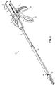
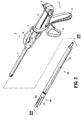
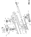
- Stapler 10 generally includes a handle assembly 12, a rotation knob 14, an articulation lever 16 and an elongated body portion 18 that is configured to engage a SULU 500.
- Stapler 10 generally includes a handle assembly 12, a rotation knob 14, an articulation lever 16 and an elongated body portion 18 that is configured to engage a SULU 500.
- a handle assembly 12 generally includes a handle assembly 12, a rotation knob 14, an articulation lever 16 and an elongated body portion 18 that is configured to engage a SULU 500.
- SULU 500 generally includes a proximal body portion 502 and a tool assembly 504.
- Proximal body portion 502 is releasably attachable to a distal end of elongated body portion 18 of stapler 10, as will be described below, and tool assembly 504 extends from a distal end of proximal body portion 502.
- Tool assembly 504 includes an anvil assembly 506 and a cartridge assembly 514.
- Anvil assembly 506 is pivotal in relation to cartridge assembly 514 from an open or unclamped position ( FIG. 3 ) to a closed or clamped position ( FIG. 4 ), as will be discussed in further detail below.
- anvil assembly 506 includes an anvil cover 507 that supports an anvil plate 508.
- Anvil plate 508 may include a plurality of staple forming depressions 513 configured such that, when tool assembly 504 is in the clamped position ( FIG. 1 ), staple forming depressions 513 are positioned in juxtaposed alignment with staple slots 568 ( FIG. 13 ) formed within cartridge assembly 514. Accordingly, as each staple "S" ( FIGS. 20-21 ) is ejected from one of staple slots 568 ( FIG. 13 ) of cartridge assembly 514, each staple "S" ( FIGS.
- FIGS. 20-21 is advanced through tissue grasped between anvil assembly 506 and cartridge assembly 514 and into one of the staple forming depressions 513 such that staples "S" ( FIGS. 20-21 ) are formed about tissue.
- Anvil plate 508 is secured to an underside of anvil cover 507 to define a channel 509 between plate 508 and cover 507 ( FIG. 6 ).
- Channel 509 defines a generally "T"-shaped configuration that is adapted to receive and guide upper beam 593a of dynamic clamping member 593 therethrough.
- Anvil cover 507 includes a proximal portion 510 having a pair of spaced-apart flanges 511, 512 that are pivotably coupled to cartridge assembly 514 on either side of cartridge assembly 514, thus allowing anvil assembly 506 to pivot relative to cartridge assembly 514 between the open position ( FIG. 3 ) and the clamped position ( FIG. 4 ).
- cartridge assembly 514 may be pivotally mounted in relation to anvil assembly 506.
- cartridge assembly 514 includes a frame member 516 which rotatably supports a conveyor assembly 530, a drive assembly 590, and a fire and reload assembly 600.
- Frame member 516 defines a generally U-shaped configuration having a base 517 and a pair of spaced-apart sidewalls 518 that define an elongated channel 519 therebetween.
- Elongated channel 519 is configured to receive conveyor assembly 530 therein.
- frame member 516 includes a pair of opposed proximal apertures 522 defined through sidewalls 518 at proximal ends 521 thereof that are configured to rotatably support the proximal end of conveyor assembly 530 and a pair of distal apertures 524 defined through sidewalls 518 at distal ends 523 thereof that are configured to rotatably support the distal end of conveyor assembly 530.
- Conveyor assembly 530 generally includes a central support member 531 and first and second conveyors 540, 550, respectively, disposed on either side of central support member 531.
- Central support member 531 defines an elongated channel 532 ( FIG. 6 ) therethrough that is configured to receive and guide translation of dynamic clamping member 593 to cut tissue grasped between anvil assembly 506 and cartridge assembly 514.
- Central support member 531 further includes an outwardly-flanged lower portion 535 that, as best shown in FIG. 6 , extends through a slot defined within base 517 of frame member 516 to secure central support member 531 and frame member 516 to one another.
- Each of the conveyors 540, 550 includes a pair of conveyor chains 541, 551, respectively, that define looped configurations ( FIG.
- each conveyor 540, 550 is disposed about a proximal sprocket 542, 552, respectively, at the proximal end thereof and a distal sprocket 544, 554, respectively, at the distal end thereof.
- Proximal sprockets 542, 552 are rotatably supported within opposed proximal apertures 522 defined through sidewalls 518 of frame member 516.
- Distal sprockets 544, 554 are rotatably supported within opposed distal apertures 524 defined through sidewalls 518 of frame member 516 and within aperture 534 defined through distal disc 533 of central support member 531.
- First and second conveyors 540, 550, respectively, of conveyor assembly 530 are substantially similar to one another and, thus, only first conveyor 540 will be described hereinbelow to avoid unnecessary redundancy.
- the conveyor chains 541 of conveyor 540 cooperate with one another to support a plurality of conveyor links 566 thereon along a substantial portion of conveyor chains 541.
- Conveyor links 566 are shaped complementary to one another such that adjacent conveyor links 566 mate with one another to form an upper, tissue-contacting surface 570 of conveyor 540 on the upper portion thereof and a lower portion 572 of conveyor 540 (see FIGS. 18, 18A and 19 ).
- conveyor links 566 mate with one another to form an upper, tissue-contacting surface 556 of second conveyor 550 on the upper portion thereof.
- Upper, tissue-contacting surfaces 570, 556 of first and second conveyors 540, 550, respectively, are disposed on either side of channel 574 (see FIG. 3 ) and together form the upper, tissue-contacting surface of cartridge assembly 514.
- Conveyor links 566 also cooperate to form three linear rows of staple slots 568 (although greater or fewer than three rows of staple slots are contemplated) extending longitudinally along upper, tissue-contacting surfaces 570, 556 of conveyors 540, 550, respectively.
- a staple "S” is housed within each of staple slots 568. Further, each staple slot 568 is configured to receive a portion of a pusher 580 to fire, or eject staples "S" from cartridge assembly 514. More specifically, pushers 580, as shown in FIG.
- a set of conveyor links 566 mate with one another to form the upper, tissue-contacting surface 570 of conveyor 540 (and, similarly, upper, tissue-contacting surface 556 of conveyor 550), while the remainder of conveyor links 566 are disposed at other positions along conveyor chains 541, e.g., proximally of upper, tissue-contacting surface 570, on lower portion 572, about proximal sprocket 542, about distal sprocket 544, etc.
- Conveyor links 566 are rotatable along frame member 516 and about proximal and distal sprockets 542, 544, respectively.
- conveyor links 566 are rotated along the loop formed by conveyor chains 541 of conveyor 540 from a position on the upper portion of conveyor 540 wherein conveyor links 566 define upper, tissue-contacting surface 570, counter-clockwise about distal sprocket 544, proximally along lower portion 572, counter-clockwise about proximal sprocket 542, distally to form the upper, tissue-contacting surface 570, etc.
- conveyor links 566 define upper, tissue-contacting surface 570, counter-clockwise about distal sprocket 544, proximally along lower portion 572, counter-clockwise about proximal sprocket 542, distally to form the upper, tissue-contacting surface 570, etc.
- such a configuration permits a new set of conveyor links 566 (the conveyor links 566 positioned proximally of upper, tissue-contacting surface 570) to be moved into position in juxtaposed alignment with staple forming depressions 513 ( FIG. 6 ) of anvil plate 508 ( FIG.
- stapler 10 may be fired to eject a second set of staples "S" from cartridge assembly 514.
- a plurality of sets of staples "S” can be fired from SULU 500 without requiring a new SULU for each firing operation. The operation of SULU 500 in firing multiple sets of staples "S" will be described in greater detail hereinbelow.
- each pusher 580 defines three blocks 582 (although greater or fewer blocks are contemplated) that each engage the backspan of one of staples "S" (one from each of the linear rows) during firing to facilitate ejection of staples "S" from cartridge assembly 514.
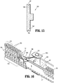
- Pushers 580 are disposed between the conveyor links 566 forming upper, tissue-contacting surface 570 of conveyor 540 and the conveyor links 566 disposed on the lower portion 572 of conveyor 540 directly beneath upper, tissue-contacting surface 570, and are configured as bi-directional pushers 580. Initially, as shown in FIG.
- pushers 580 are disposed within slots 568 defined within conveyor links 566 of lower portion 572 of conveyor 540 such that, upon actuation, cam wedges 596 of cam bars 595 contact angled surfaces 584 of pushers 580 to urge pushers 580 upwardly from slots 568 of conveyor links 566 of lower portion 572 into slots 568 defined within conveyor links 566 forming upper, tissue-contacting surface 570 of conveyor 540 to eject staples "S" therefrom.
- Pushers 580 as shown in FIG. 15 , define grooves 586 at first end 585 thereof that are configured to receive the backspans of staples "S" to guide the ejection of staples "S" from conveyor links 566.
- conveyor 540 is rotated such that the conveyor links 566 which housed the previously fired stapled, which now house pushers 580 disposed within slots 568 thereof, are rotated about distal sprocket 544 to lower portion 572 of conveyor 540, while a new set of conveyor links 566 (which include un-fired staples "S" therein) are translated distally along conveyor 540 to form upper, tissue-contacting surface 570 or a portion of surface 570 of conveyor 540.
- pushers 580 are oriented upside-down (due to the rotation of conveyor links 566 about distal sprocket 544). Accordingly, pushers 580 also define grooves 588 at a second end 587 thereof that are configured to receive the backspans of staples "S" therein to guide the ejection of staples "S” and also include angled surfaces 589 that are configured to cam along cam wedges 596 of cam bars 595 when in this upside-down orientation. That is, pushers 580 are operable to eject staples "S" from conveyor links 566 regardless of the orientation of pushers 580.
- drive assembly 590 includes a drive bar 591 having a bifurcated proximal end 592 and a distal end 594 that engages dynamic clamping member 593.
- Drive assembly 590 further includes a pair of cam bars 595 coupled to drive bar 591 on either side thereof.
- Cam bars 595 each include an angled distal end surface defining a cam wedge 596 configured to slidably contact complementary-shaped angled surfaces 584, 589 of pushers 580 (depending on the orientation of pushers 580) (see FIGS. 14-15 ) upon distal translation of drive bar 591 to urge pushers 580 upwardly to eject staples "S" from slots 568 of conveyor links 566.
- a tab 597 ( FIG. 10 ) is received through slots 598 defined within each of cam bars 595 and through slot 599 defined within drive bar 591 to secure cam bars 595 and drive bar 591 in spaced-relation relative to one another.
- Dynamic clamping member 593 is disposed at distal end 594 of drive bar 591.
- Dynamic clamping member 593 includes an upper beam 593a and a lower beam 593b interconnected by an upright-member 593c.
- Upright member 593c defines a cutting blade 593d to facilitate advancement of dynamic clamping member 593 through tissue.
- upper beam 593a of dynamic clamping member 593 is advanced into the upper transverse portion of T-shaped channel 509 defined between plate 508 and cover 507 of anvil assembly 506, distal beam 593b is translated along the exterior of frame member 516 and central support member 531, and upright member 593c is translated into the upright portion of T-shaped channel 509 of anvil assembly 506 and elongated channel 532 of central support member 531 (the upright portion of T-shaped channel 509 and elongated channel 532 of central support member 531 cooperate with one another to define channel 574 ( FIG. 3 )) to pivot anvil assembly 506 relative to cartridge assembly 514 to the clamped position ( FIG. 4 ).
- dynamic clamping member 593 is incrementally advanced further through SULU 500 such that cam bars 595 are urged into contact with pushers 580 to fire staples "S" therefrom and such that dynamic clamping member 593 is advanced through tissue to cut tissue between conveyors 540, 550 of cartridge assembly 514.
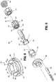
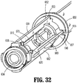
- fire and reload assembly 600 generally includes a pair of laterally-opposed reload bars 660, 670, a non-rotary driver 610, a rotary coupler 620, a proximal cam 630, a distal cam 640, and a lock ring 650.
- Fire and reload assembly 600 is configured to alternately transition between a firing mode, wherein drive bar 591 is selectively advancable to eject staples "S" from cartridge assembly 514 and to cut tissue grasped between anvil assembly 506 and cartridge assembly 514, and a reload mode, wherein reload bars 660, 670 are advancable distally to urge conveyor links 566 to rotate about conveyors 540, 550 such that a new set of conveyor links 566 is positioned to form the upper, tissue-contacting surfaces 570, 556 of conveyors 540, 550, respectively, of cartridge assembly 514, while conveyor links 566 which housed the fired staples are rotated about distal sprockets 544, 554 to the lower portion of cartridge assembly 514. Due to this configuration, as can be appreciated, and as will be described in greater detail below, each complete firing operation is followed by a reloading operation that reloads SULU 500 for subsequent firing.
- Proximal end 592 of drive bar 591 defines a bifurcated configuration. More specifically, proximal end 592 of drive bar 591 includes an upper arm 681 and a lower arm 682 that are spaced-apart from one another and extend proximally from drive bar 591 to form proximal end 592 of drive bar 591. Upper and lower arms 681, 682, respectively, each define an opposed cut-out 683, 684 at free end 685, 686, respectively, thereof. Opposed cut-outs 683, 684 receive block protrusions 622 of rotary coupler 620 when fire and reload assembly 600 is disposed in the firing mode such that advancement of rotary coupler 620 effects similar advancement of drive bar 591.
- cut-outs 683, 684 are offset relative to block protrusions 622 of rotary coupler 620 such that rotary coupler 620 is no longer coupled to upper and lower arms 681, 682 of drive bar 591 and, thus, translation of rotary coupler 620 does not effect corresponding translation of drive bar 591.
- upper and lower arms 681, 682 are slidably supported within vertically-opposed slots 612, 613, respectively, defined within non-rotary driver 610 of fire and reload assembly 600 (see FIGS. 26-27 ), to guide translation of drive bar 591 when fire and reload assembly 600 is operating in the firing mode.
- laterally-opposed reload bars 660, 670 similar to arms 681, 682 of drive bar 691, each include a proximal end 662, 672 defining a cut-out 664, 674, respectively.
- Laterally-opposed reload bars 660, 670 are offset 90 degrees relative to upper and lower arms 681, 682 of drive bar 591 and are slidably supported within laterally-opposed slots 614, 615, respectively, defined within non-rotary driver 610 to guide translation of reload bars 660, 670 when fire and reload assembly 600 is operating in the reload mode.
- cut-outs 664, 674 of reload bars 660, 670 are configured to receive block protrusions 622 of rotary coupler 620 when fire and reload assembly 600 is operating in the reload mode such that advancement of rotary coupler 620 effects similar advancement of reload bars 660, 670.
- cut-outs 664, 674 are offset relative to block protrusions 622 of rotary coupler 620 such that rotary coupler 620 is no longer coupled to reload bars 660, 670 and, thus, translation of rotary coupler 620 does not effect corresponding translation of reload bars 660, 670.
- Rotary coupler 620 is rotatably disposed about a proximal extension 616 of non-rotary driver 610 and, as mentioned above, is engaged to arms 681, 682 of drive bar 591 in the firing mode and to reload bars 660, 670 in the reload mode. More specifically, body portion 624 of rotary coupler 620 includes a plurality of spaced-apart block protrusions 622 disposed about the outer periphery thereof. Block protrusions 622 are spaced-apart from one another to define gaps 626 therebetween.
- rotary coupler 620 is rotatable about proximal extension 616 of non-rotary driver 610 and relative to drive bar 591 and reload bars 660, 670 to transition fire and reload assembly 600 between the firing mode and the reload mode. More specifically, in the firing mode, rotary coupler 620 is oriented such that opposed cut-outs 683, 684 of arms 681, 682, respectively, of drive bar 591 receive block protrusions 622, while reload bars 660, 670 are disposed within gaps 626.
- rotary coupler 620 is rotated such that opposed cut-outs 664, 674 of reload bars 660, 670, respectively, receive block protrusions 622, while arms 681, 682 of drive bar 591 are disposed within gaps 626.
- Rotary coupler 620 further includes a toothed proximal portion 627 and a toothed distal portion 629.
- Toothed proximal portion 627 includes a plurality of teeth, each generally defining a right triangle-shaped configuration. In other words, each tooth defines a longitudinal surface and an angled surface. The teeth are oriented similarly relative to one another to define a continuous toothed configuration about the circumference of toothed proximal portion 627.
- Toothed distal portion 629 also includes a plurality of teeth that generally define a right triangle-shaped configuration and are oriented similarly relative to one another. Alternately, different tooth configurations are envisioned.
- proximal and distal cams 630, 640 are stationarily disposed at the proximal and distal ends, respectively, of fire and reload assembly 600.
- Proximal cam 630 includes a toothed distal portion 632 that includes a plurality of teeth that are shaped complementarily to the teeth of toothed proximal portion 627 of rotary coupler 620. The teeth of proximal cam 630 are initially aligned with the teeth of toothed proximal portion 627 of rotary coupler 620.
- Proximal cam 630 is biased distally by a biasing member 634.
- Distal cam 640 includes a toothed proximal portion 642 that includes a plurality of teeth that are shaped complementarily to the teeth of toothed distal portion 629 of rotary coupler 620. Initially, the teeth of distal cam 640 are offset relative to the teeth of toothed distal portion 629 of rotary coupler 620.
- Proximal cam 630 and distal cam 640 cooperate to rotate rotary coupler 620 upon full advancement and retraction of fire and reload assembly 600 such that fire and reload assembly 600 is transitioned between the firing mode and the reload mode after each full advancement and retraction of fire and reload assembly 600. More specifically, upon full advancement of fire and reload assembly 600, rotary coupler 620 is urged distally such that toothed distal portion 629 of rotary coupler 620 ultimately contacts toothed proximal portion 642 of distal cam 640.
- rotary coupler 620 is pulled proximally such that toothed proximal portion 627 of rotary coupler 620 ultimately contacts toothed distal portion 632 of proximal cam 630.
- toothed proximal portion 627 of rotary coupler 620 Prior to contacting proximal cam 630, but after contacting and being rotated by distal cam 640, the teeth of toothed proximal portion 627 of rotary coupler 620 are aligned with the teeth of proximal cam 630 due to the rotation of rotary coupler 620 from its original position, as described above.
- rotary coupler 620 is rotated relative to proximal cam 630 such that the respective teeth are complementarily offset relative to one another, thus allowing rotary coupler 620 and proximal cam 630 to mate with one another.
- the rotation of rotary coupler 620 upon contact with proximal cam 630 during retraction of fire and reload assembly 600 is similar in direction to the rotation of rotary coupler 620 upon contact with distal cam 640.
- each rotation corresponds to a partial rotation of rotary coupler 620 between the firing mode and the reload mode.
- full advancement of fire and reload assembly 600 occurs when drive bar 591 is moved distally to eject staples "S" from SULU 500 and to advance dynamic clamping member 593 to cut stapled tissue.
- rotary coupler 620 contacts distal cam 640 and is rotated partially from the firing mode towards the reload mode, but is not rotated enough so as to disengage drive bar 591 from rotary coupler 620. Accordingly, with drive bar 591 and rotary coupler 620 still engaged, fire and reload assembly 600 can be retracted to thereby retract drive bar 591.
- rotary coupler 620 contacts proximal cam 630 and is rotated from the partially rotated orientation to the reload mode, wherein arms 681, 682 of drive bar 591 are disengaged from rotary coupler 620 and wherein reload bars 660, 670 are engaged to rotary coupler 620.
- reload bars 660, 670 are advanced to urge a new set of conveyor links 566 into position to form upper, tissue-contacting surfaces 570, 556 of conveyors 540, 550, respectively, of cartridge assembly 514 for subsequent firing.
- Contact of rotary coupler 620 with distal cam 640 at the end of the reload stroke rotates rotary coupler 620 partially back towards the firing mode and, upon retraction, contact of rotary coupler 620 with proximal cam 630 rotates rotary coupler 620 back into engagement with drive bar 591 such that fire and reload assembly 600 is returned to the firing mode for subsequent firing.
- lock ring 650 provides a locking feature that inhibits advancement of reload bars 660, 670 when fire and reload assembly 600 is in the firing mode, and inhibits advancement of drive bar 591 when fire and reload assembly 600 is in the reload mode.
- Lock ring 650 as shown in FIG. 8 , includes a central aperture 651 and two pairs of opposed detent portions 652, 655.
- Drive bar 591 includes a pair of opposed intermediate cut-outs 687, 688 that are configured to be received within detent portions 652 of lock ring 650.
- Reload bars 660, 670 each include a distal cut-out 666, 676, respectively, that is configured to be received within detent portions 655.
- Each detent portion 652, 655 further includes a slot 653, 656 adjacent respective detent portions 652, 655 and an angled surface 654, 657, respectively, leading to slots 653, 656, respectively.
- Slots 653 of the first pair of detent portions 652 and slots 656 of the second pair of detent portions 655 are not equally-spaced about lock ring 650, but, rather, are offset relative to one another. Due to this configuration, as will be described below, when drive bar 591 is aligned with slots 653, reload bars 660, 670 are offset relative to slots 656 and, similarly, when reload bars 660, 670 are aligned with slots 656, drive bar 591 is offset relative to slots 653, thus providing the locking feature of lock ring 650.
- Lock ring 650 is rotatable between a first position, wherein drive bar 591 is aligned with slots 653 of detent portions 652 and reload bars 660, 670 are offset relative to slots 656 of detent portions 655, and a second position, wherein reload bars 660, 670 are aligned with slots 656 of detent portions 655 and drive bar 591 is offset relative to slots 653 of detent portions 652.
- drive bar 591 In the first position, which corresponds to the firing mode, drive bar 591 is permitted to be translated through lock ring 650 due to the alignment of drive bar 591 with slots 653, while distal cut-outs 666, 676 of reload bars 660, 670, respectively, are disposed about detent portions 655, inhibiting translation of reload bars 660, 670.
- reload bars 660, 670 In the second position, which corresponds to the reload mode, reload bars 660, 670 are permitted to be translated through lock ring 650 due to the alignment of reload bars 660, 670 with slots 656, while intermediate cut-outs 687, 688 of drive bar 591 are disposed about detent portions 652, inhibiting translation of drive bar 591.
- Angled surfaces 654, 657 of detent portions 652, 655, respectively, facilitate the rotation of lock ring 650 between the first and second positions. More specifically, as drive bar 591 is advanced distally during the firing mode, drive bar 591 is urged into contact with angled surfaces 654 of detent portions 652 to rotate lock ring 650, thus ensuring that drive bar 591 is aligned with slots 653 and that distal cut-outs 666, 676 of reload bars 660, 670, respectively, are disposed about detent portions 655.
- reload bars 660, 670 In the reload mode, during distal advancement of reload bars 660, 670, reload bars 660, 670, are urged into contact with angled surfaces 657 of detent portions 655 to rotate lock ring 650 in the opposite direction, thus ensuring that reload bars 660, 670 are aligned with slots 656 and that intermediate cut-outs 687, 688 of drive bar 591 are disposed about detent portions 652.
- a biasing member 658 and centering plunger 659 return lock ring 650 to a centered position in the absence of drive bar 591 or reload bars 660, 670 urging lock ring 650 to rotate to the first and second positions, respectively.
- stapler 10 in conjunction with FIG. 1 , stapler 10, as mentioned above, generally includes a handle assembly 12, a rotation knob 14, an articulation lever 16, and an elongated body portion 18 that is configured to engage SULU 500.
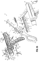
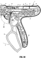
- Handle assembly 12 is selectively operable, as will be described below, to clamp tissue between anvil assembly 506 and cartridge assembly 514, to fire a set of staples "S" ( FIGS. 20-21 ) from SULU 500, and for reloading SULU 500 for subsequent firing. More specifically, handle assembly 12 is transitionable between a grasper mode and a firing mode for grasping tissue between anvil assembly 506 and cartridge assembly 514 and for incrementally firing a plurality of staples "S" through tissue and dividing tissue grasping between anvil assembly 506 and cartridge assembly 514, respectively. Handle assembly 12 generally includes a stationary handle portion 20, a trigger or movable handle portion 22, a barrel portion 24, and retraction knobs 26.
- Handle assembly 12 is formed from a pair of housing sections 12a and 12b that cooperate to form stationary handle portion 20 and barrel portion 24. Housing sections 12a and 12b also define a cavity 30 for receiving the internal components of handle assembly 12, which will be described in greater detail hereinbelow.
- movable handle 22 of handle assembly 12 is pivotably supported between housing sections 12a and 12b about a pivot member 32 ( FIG. 33 ).
- a biasing member 34 has a first end secured about a post 36a on housing half-section 12a and a second end which engages a post 36b supported on movable handle 22 to bias movable handle 22 away from stationary handle 20 to a non-compressed position corresponding to the open or unclamped position of tool assembly 504 of SULU 500 (see FIG. 1 ).
- An actuation shaft 38 is supported within barrel portion 24 of handle assembly 12 and includes a toothed rack 40.
- a driving pawl 42 having a rack engagement finger 44 with laterally extending wings 44a and 44b is pivotably mounted to one end of movable handle 22 about post 36b.
- a biasing member 48 is positioned to urge engagement finger 44 of driving pawl 42 towards toothed rack 40 of actuation shaft 38.
- Movable handle 22 is pivotable to move engagement finger 44 of driving pawl 42 into contact with toothed rack 40 of actuation shaft 38 to advance actuation shaft 38 linearly in the distal direction.
- the forward end of actuation shaft 38 includes a recess 39 ( FIG. 39 ) for rotatably receiving the proximal end 50 of a control rod 52 ( FIG.
- a vertical pawl 54 is movably supported within handle assembly 12 and is biased towards a cutout 58 in actuation shaft 38 by biasing member 56. Vertical pawl 54 is movable into engagement with cutout 58 and toothed rack 40 to retain actuation shaft 38 in a longitudinally fixed position.
- a retraction mechanism 57 which includes retraction knobs 26 (See FIG. 1 ) is connected to the proximal end of actuation shaft 38 by a coupling rod 60.
- Coupling rod 60 includes right and left engagement portions 62a and 62b for receiving retraction knobs 26 and a central portion 62c which is dimensioned and configured to translate within a pair of longitudinal slots 64 formed in actuation shaft 38 adjacent the proximal end thereof.
- a release plate 66 is operatively associated with actuation shaft 38 and is mounted for movement with respect thereto in response to manipulation of retraction knobs 26.
- a pair of spaced-apart pins 68 extend outwardly from a lateral face of actuation shaft 38 to engage a pair of corresponding angled cam slots 70 formed in release plate 66.
- pins 68 cam release plate 66 downwardly with respect to actuation shaft 38 and with respect to toothed rack 40 such that the bottom portion of release plate 66 extends below toothed rack 40 to disengage vertical pawl 54 and engagement finger 44 of driving pawl 42 from toothed rack 40.
- a transverse slot 72 ( FIG. 36 ) is formed at the proximal end of release plate 66 to accommodate the central portion 62c of coupling rod 60.
- Coupling rod 60 is biased distally by spring 76 ( FIG. 36 ) which is secured at one end to coupling rod portion 60 via connector 78 and at the other end to post 80 on actuation shaft 38.
- spring 76 FIG. 36
- release plate 66 is urged towards a position above toothed rack 40.
- Elongated slots 74 are defined in the barrel portion 24 of handle assembly 12 to accommodate the longitudinal translation of coupling rod 60 as retraction knobs 26 are pulled rearwardly to retract actuation shaft 38 and thus retract control rod 52 ( FIG. 41 ) rearwardly.
- handle assembly 12 includes a retraction arm 85 which is rotatably supported within barrel portion 24 of handle assembly 12.
- a torsion spring 87 is positioned to urge retraction arm 85 in counter-clockwise rotation as viewed in FIG. 46 .
- Retraction arm 85 includes a protrusion 85a which is positioned within a notch 89 of actuation shaft 38. As spring 87 urges arm 85 in counter-clockwise rotation, protrusion 85a engages actuation shaft 38 to urge actuation shaft 38 proximally within handle assembly 12.
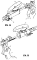
- handle assembly 12 of stapler 10 includes a grasper jaw mechanism 100 which includes a disconnect link assembly 102 and an actuator assembly 104.
- disconnect link assembly 102 functions to prevent engagement of vertical pawl 54 with actuation shaft 38 when handle assembly 12 is in the grasper mode, allowing for proximal and distal movement of actuation shaft 38 to move anvil assembly 506 relative to cartridge assembly 516 between the open and clamped positions only (not for firing drive assembly 590).
- Actuator assembly 104 prevents the movable handle 22 from returning fully to the non-compressed position when handle assembly 12 is in grasper mode to prevent driving pawl 42 from engaging toothed rack 40.
- Disconnect link assembly 102 includes a proximal link 106 and a distal link 108.
- Proximal link 106 has a proximal end pivotally secured to a cylindrical boss 109 formed on movable handle 22 about a pivot member 106a and a distal end pivotally secured to a proximal end of distal link 108 via a pivot member 109.
- Distal link 108 is linearly slidable along a track defined within housing cavity 30 of handle assembly 12 and includes an angled stepped portion 108a formed at its proximal end.
- Distal link 108 is slidably positioned to engage a cam surface 110 formed on vertical pawl 54.
- actuation shaft 38 is free to move proximally as will be discussed in further detail below.
- actuator assembly 104 includes actuator button 28, a pawl arm 116 and a grasping pawl 118.
- actuator button 28 is selectively movable between a centered position and an off-centered position for transitioning handle assembly 12 of stapler 10 between the grasper mode and the firing mode.
- Pawl arm 116 is slidably received in a recess 120 ( FIG. 46 ) formed in movable handle 22.
- a biasing member 122 is positioned within recess 120 to urge pawl arm 116 towards an extended position ( FIG. 61 ).
- Pawl arm 116 has upper and lower spaced triangular cam surfaces 116a and 116b which will be discussed in further detail below.
- Grasping pawl 118 is pivotally supported within a slot 118a ( FIG. 58 ) formed in a distal end of pawl arm 116.
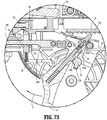
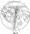
- a biasing member 124 ( FIG. 36 ) is positioned to urge a piston 124a into grasping pawl 118 to urge grasping pawl 118 in a counter-clockwise direction as viewed in FIG. 74 . Pivoting movement of grasping pawl 118 allows pawl arm 116 to ratchet or slide over toothed rack 40 of actuation shaft 38 ( FIG. 74 ).
- actuator button 28 is slidably positioned through a bore 126 ( FIG. 36 ) formed in movable handle 22 from a centered position ( FIG. 59 ) to an off-center position ( FIG. 70 ).
- Bore 126 is substantially orthogonal to recess 120 such that actuator button 28 is slidably positioned between upper and lower cam surfaces 116a and 116b of pawl arm 116.
- Actuator button 28 is substantially cylindrical and includes a linear rib 128 and a V-shaped cam member 130. V-shaped cam member 130 defines a slot 132 ( FIG.
- actuator button 28 which is configured to receive lower cam surface 116b of pawl arm 116 when actuator button 28 is in the centered position and pawl arm 116 is in an extended position within recess 120.
- Actuator button 28 defines recesses 134 ( FIG. 59 ) on opposite sides of slot 132. Opposite ends of actuator button 28 extend from opposite sides of housing sections 12a and 12b of handle assembly 12 ( FIG. 59 ) and can be pressed by a surgeon from either side of handle assembly 12 to move actuator button 28 linearly through bore 126 in either direction to move actuator button 28 from the centered position to the off-center position.
- actuator button 28 When actuator button 28 is moved linearly within bore 126, lower cam surface 116b is engaged by V-shaped cam member 130 to urge pawl arm 116 from its initial, extended position, downwardly within recess 120 to its retracted position.
- actuator button 28 When actuator button 28 is moved linearly to its off-center position and pawl arm 116 is cammed to its retracted position, the apex of lower cam surface 116b is received within one of recesses 134 to retain actuator button 28 in the off-centered, or actuated position (see FIG. 70 ).
- grasping pawl 118 When pawl arm 116 is moved to the retracted position, grasping pawl 118 is also moved from an initial extended position, to a retracted position and is withdrawn from a slot 136 of actuation shaft 38 ( FIG. 40 ).
- actuator button 28 is supported on movable handle 22 and extends through each of housing sections 12a and 12b of handle assembly 12.
- arc shaped slots 90 are provided in each of housing sections 12a and 12b. Raised surfaces or bosses 92, are provided about a portion of arc shaped slots 90 to prevent depression of actuator button 28 until movable handle 22 has been moved to a compressed position.
- rotation knob 14 is constructed from molded half-sections 14a and 14b.
- Each half-section 14a, 14b includes an internal annular projection 450 on its proximal end which is received within an annular recess 452 formed in the distal end of handle assembly 12 to rotatably secure rotation knob 14 to handle assembly 12.
- a distal end of each mold half-sections 14a and 14b defines a recess 454 ( FIG. 47 ) for non-rotatably receiving a fitting 456.
- Fitting 456 includes cutouts 456a for receiving a projection 458 ( FIG. 47 ) formed on half-sections 14a and 14b. Fitting 456 is fixedly secured to the proximal end of body 18 such that rotation of rotation knob 14 effects rotation of body 18 and, thus, SULU 500 ( FIG. 1 ).
- articulation mechanism 300 is supported in a receptacle 15 formed in rotatable knob 14 ( FIG. 41 ) and is configured to articulate an articulatable SULU.
- SULU 500 FIG. 1
- SULU 500 FIG. 1
- stapler 10 may be configured as a cross-compatible device that is usable with articulating SULUs as well as non-articulating SULUs. When used with non-articulating SULU, articulation assembly 300 would simply be inoperable.
- Articulation mechanism 300 includes articulation lever 16, a mechanism cover 320, biasing members 322, an upper clutch 324, a lower clutch 326, a main shaft 328, and a translation member 330.
- Lower clutch 326 is rotatably fixed within receptacle 15 and includes a circular serrated portion 334 having a series of shallow serrations 336 and a pair of spaced deep serrations 338 ( FIG. 42 ).
- Lower clutch 326 also defines a central throughbore 340 which is dimensioned to receive main shaft 328.
- Upper clutch 324 is rotatably fixed to main shaft 328 and includes a base portion 344 having an upper face 350 and a lower face 352 ( FIG. 44 ).
- Lower face 352 includes a plurality of spaced projections 354 which are received within deep and shallow serrations 336 and 338 of lower clutch 326.
- Biasing members 322 urge lower face 352 of upper clutch 324 into engagement with serrated portion 334 of lower clutch 326 to releasably secure articulation mechanism 300 in a fixed position and, thus, to releasably secure the articulatable SULU at a fixed angle of articulation.
- Main shaft 328 includes a substantially cylindrical body portion 358 and a disc-shaped base portion 360.
- Base portion 360 defines an opening 362 which receives a cam member 364.
- Body portion 358 is dimensioned to extend through both lower clutch 326 and upper clutch 324 such that base portion 360 is positioned beneath upper clutch 324 and lower clutch 326 within receptacle 15 of rotation knob 14.
- Translation member 330 ( FIG. 42 ) includes a cam slot 376 dimensioned to slidably receive cam member 364 of main shaft 328.
- Translation member 330 When cam member 364 is driven in rotation, translation member 330 is urged to move linearly. Translation member 330 is configured to engage an articulation link 333 of an articulatable SULU such that linear movement of translation member 330 effects linear movement of the articulation link 333 to effect articulation of the articulatable SULU.
- stapler 10 includes a SULU release link assembly 200 which includes a SULU release link 202, a SULU release button 204 and a biasing member 206.
- Release button 204 includes a gripping surface 204a and is slidably positioned within a cavity 208 formed in rotation knob 14 ( FIG. 47 ).
- Release button 204 includes a central wall 210 and a transversely extending post 212.
- Biasing member 206 is positioned between a proximal surface of central wall 210 and a spring post 214 formed on rotation knob 14 to urge release button 204 distally within cavity 208.
- release link 202 includes a proximal end 202a, an elongated central body portion 202b and a distal end 202c.
- Proximal end 202a defines a blind bore (not shown) dimensioned to receive post 212 of release button 204 ( FIG. 34 ) such that biasing member 206 urges button 204 and link 202 in a distal direction.
- Distal end 202c of release link 202 includes a distal abutment member 216 and a transverse extension 218.
- a proximal end of transverse extension 218 defines a ramped cam surface 220 and a distal end of transverse extension 218 defines a tab retention recess 220 with abutment member 216.
- Transverse extension 218 also includes a rectangular opening 222.
- elongated body portion 18 of stapler 10 includes an outer tube 230 and an inner body portion 232 through which control rod 52 is inserted.
- Inner body 232 is received within outer tube 230 and includes a distal end 232a defining a pair of diametrically-spaced longitudinal channels 234 ( FIG. 52 ) and proximally-spaced annular channel 235 which intersects longitudinal channels 234.
- Inner body 232 also defines a recess 236 ( FIG. 48 ) for slidably receiving release link 202 such that release link is slidably positioned between outer tube 230 and inner body portion 232.
- a projection 238 extending radially outwardly from body 232 extends into rectangular opening 222 of transverse extension 218 of release link 202.
- a spring 240 is positioned within rectangular opening 222 between projection 238 and a distal end of opening 222 ( FIG. 38 ) to urge release link 202 distally.
- a hook 242 is positioned between outer tube 230 and inner body portion 232 adjacent ramped cam surface 220.
- Hook 242 includes an elongated body 244 having a transverse distal end 246. Transverse distal end 246 is positioned adjacent to a cutout 248 in control rod 52.
- Hook 242 is urged by a biasing member 250 to a position in which distal end 246 of hook 242 is located externally of cutout 248.
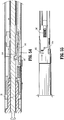
- release link 202 is moved proximally against the urging of biasing members 206 and 240 by pulling release button 204 proximally, cam surface 220 moves distal end 246 of hook 242 into cutout 248 of control rod 52. If control rod 52 is not in its retracted position shown in FIG.
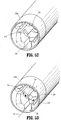
- tabs 260 in order to fasten a SULU 500 to elongated body 18 of stapler 10, tabs 260 must be aligned with and advanced through longitudinal channels 234 of inner body 232 in the direction indicated by arrow "H” in FIG. 53 and rotated into annular channel 235 in the direction indicated by arrow "I".
- abutment member 216 is positioned to engage a tab 260 as tab 260 exits longitudinal channel 234.
- release link 202 moves proximally in the direction indicated by arrow "J" in FIG. 51 against the urging of biasing members 206 and 240 until tab 260 is positioned entirely within annular channel 235.
- hook 242 is moved by cam surface 220 into cutout 248 of control rod 52.
- tab 260 is positioned entirely within annual channel 235, SULU 500 is rotated in relation to elongated body portion 18 in the direction indicated by arrow "K” in FIG. 56 such that tabs 260 move out of alignment with longitudinal channels 234 ( FIG. 56 ).
- release link 202 is returned to its distal position in the direction indicated by arrow "L” in FIG. 57 such that a tab 260 is retained within tab retention recess 220a.
- tab retention recess 220a When tab 260 is positioned within tab retention recess 220a, SULU 500 is prevented from rotating in relation to body portion 18 and, thus, is locked onto body portion 18.
- SULU release button 204 is moved proximally ( FIG. 50 ) in the direction indicated by arrow "M" in FIG. 50 to retract abutment member 216 proximally and remove tab 260 from tab retention recess 220a.
- tab 260 clears recess 220a
- SULU 500 can be rotated to align tabs 260 with longitudinal channels 234 and SULU 500 can be detached from body portion 18.
- Stapler 10 also includes a sensor mechanism 400 for preventing operation of stapler 10 before a SULU 500 has been attached to body portion 18 of stapler 10.
- sensor mechanism 400 includes a first link 402, a spacer 404, a connecting tube 406, an articulation locking member 408, a second link 410, and an actuation shaft locking member 412.
- First link 402 includes a plate-like member which is supported between control rod 52 and inner body portion 232 of elongated body portion 18 of the stapler 10 on a flat surface which is ground into control rod 52. Prior to attachment of SULU 500 to elongated body portion 18, the distal end 402a ( FIG.
- first link 402 is positioned to engage the proximal end of SULU 500 when a SULU 500 is attached to body portion 18.
- First link 402 includes a hole 414 ( FIG. 41 ) which is dimensioned to receive a protrusion 416 ( FIG. 48 ) formed on spacer 404 spacer 404 fits between first link 402 and an inner surface of outer tube 230 with a slight interference.
- Spacer 404, link 402 and the flat surface on control rod 52 function together to prevent control rod 52 from rotating in housing 232. This ensures proper rotational alignment between hook 242 and notch 248 in control rod 52.
- the proximal end 402b of first link 402 abuts the distal end of connecting tube 406 such that linear movement of first link 402 effects linear movement of sensor tube 406.
- Connecting tube 406 is slidably positioned about control rod 52 and has a proximal end 406a which abuts a distal face 408a of locking member 408 ( FIG. 50 ).
- Locking member 408 is also slidably positioned about control rod 52.
- Connecting tube 406 is moved proximally by first link 402, locking member 408 is also moved proximally.
- Lock member 408 is substantially cylindrical and includes a lock tab 420, an upper flat 421 for supporting translation member 330 of articulation mechanism 300.
- Second link 410 ( FIG. 36 ) has a distal end 410a positioned to engage the proximal end 408b of locking member 408 and a proximal end 410b positioned to engage locking member 412.
- Distal end 410a of second link 410 includes an enlarged head 426 positioned to abut the proximal face of locking member 408.
- Proximal end 410b includes a stepped portion 428 which is positioned to engage a wing 430 formed on locking member 412.
- a biasing member 440 urges second link 410 distally out of engagement with locking member 412.
- Locking member 412 is pivotally secured within handle assembly 12 between housing sections 12a and 12b about pivot member 432.
- a biasing member 436 urges locking member 412 into a slot 434 ( FIG. 40 ) formed in actuation shaft 38 to lock actuation shaft 38 in its retracted position.
- proximal end 410b of second link 410 engages wing 430 of locking member 412 to disengage locking member 412 from actuation shaft 38 to allow for distal movement of actuation shaft 38.
- locking member 412 Prior to attachment of SULU 500 to stapler 10, locking member 412 is positioned in slot 434 of actuation shaft 38 to prevent movement of shaft 38.
- SULU 500 When SULU 500 is inserted into distal end 232a of inner body 232 ( FIG. 48 ), the proximal end of SULU 500 engages first link 402 and moves first link 402, connecting tube 406, locking member 408 and second link 410 proximally.
- second link 410 moves proximally, proximal end 410b of link 410 engages wing 430 of locking member 412 to pivot locking member 412 from within slot 434 of actuation shaft 38 to unlock actuation shaft 38.
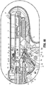
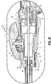
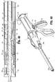
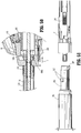
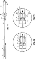
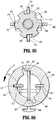
- stapler 10 The use and operation of stapler 10 is described with reference to FIGS. 59-91 .
- fire and reload assembly 600 is disposed in the firing mode, wherein drive bar 591 is engaged to rotary coupler 620 (see FIGS. 30-31 and 63-64 ).
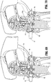
- actuator button 28 With reference to FIGS. 59-61 , with actuator button 28 is in its centered position, as mentioned above, pawl arm 116 is urged to its extended position by biasing member 122.
- grasping pawl 118 is positioned to extend into a slot 136 ( FIG. 61 ) formed in actuation shaft 38. This position corresponds to the grasper mode of handle assembly 12.
- driving pawl 42 engages an abutment 138 on actuation shaft 38 ( FIG. 61 ) to advance the actuation shaft 38 distally in the direction indicated by arrow “B” in FIG. 61 to move control rod 52 distally.
- Distal translation of control rod 52 in turn, translates rotary coupler 620 distally, which urges drive bar 591 and dynamic clamping member 593 distally to move SULU 500 to the clamped position, as described above.
- control rod 52 is advanced partially distally upon compression of movable handle 22 towards stationary handle 20 such that rotary coupler 620 is urged partially distally, thus urging drive bar 591 distally such that upper beam 593a of dynamic clamping member 593 is advanced into the upper transverse portion of T-shaped channel 509, distal beam 593b is translated along the exterior of frame member 516 and central support member 531, and upright member 593c is translated into channel 574 to pivot anvil assembly 506 relative to cartridge assembly 514 to the clamped position (see FIGS. 3-6 ).
- This partial advancement of drive bar 591 may correspond to about a 15mm increment of drive bar 591, although other incremental distances are also contemplated depending on the configuration of the SULU.
- control rod 52 Upon return of movable handle 22 to the non-compressed position, control rod 52 is returned proximally such that rotary coupler 620 is returned proximally.
- Proximal translation of rotary coupler 620 effects proximal translation of drive bar 591 (e.g., about 15mm in the proximal direction) such that upper beam 593a is removed from the upper transverse portion of T-shaped channel 509, distal beam 593b is translated proximally of the exterior of frame member 516 and central support member 531, and upright member 593c is removed from channel 574 to pivot anvil assembly 506 relative to cartridge assembly 514 back to the unclamped position (see FIGS. 3-6 ).
- rotary coupler 620 With rotary coupler 620 only translating partially distally (e.g., a 15mm increment) and subsequently returning proximally, rotary coupler 620 remains proximal of distal cam 640 and, thus, fire and reload assembly 600 remains disposed in the firing mode as handle assembly 12 is repeatedly compressed and released while in the grasper mode. That is, with handle assembly 12 in the grasper mode, anvil assembly 504 is repeatedly pivotable between the open position ( FIG. 3 ) and the clamped position ( FIG. 4 ), as described above, without transitioning fire and reload assembly 600 to the reload position.
- distal link 108 is also moved distally in the direction indicated by arrow "C” in FIG. 61 such that stepped portion 108a of distal link 108 engages cam surface 110 of vertical pawl 54 to urge vertical pawl 54 downwardly in the direction indicated by arrow “D” in FIG. 61 against the bias of spring 112 away from cutout 58 of actuation shaft 38.
- handle assembly 12 is transitioned to the firing mode. More specifically, when movable handle 22 is moved to the compressed position and actuator button 28 is moved from the centered position to the off-center position, V-shaped cam member 130 engages lower cam surface 116b on pawl arm 116 to retract pawl arm 116 in the direction indicated by arrow "F" within recess 120 ( FIG. 68 ) of movable handle 22 and retract grasping pawl 118 from within slot 136 of actuation shaft 38. When grasping pawl 118 is removed from slot 136, biasing member 34 ( FIG.
- driving pawl 42 engages toothed rack 40 of actuation shaft 38 to advance actuation shaft 38 further distally, e.g., another 15mm increment, thus advancing control rod 52 ( FIG. 60 ), rotary coupler 620 ( FIG. 63 ), and drive bar 591 ( FIG. 63 ) another increment to at least partially fire SULU 500 ( FIG. 1 ).
- This distal translation of rotary coupler 620 effects distal translation of drive bar 591 since block protrusions 622 of rotary coupler 620 are received within opposed cut-outs 683, 684 of drive bar 591. More specifically, drive bar 591 is advanced distally an additional increment relative to lock ring 650, rotating lock ring 650 to the first position, thus inhibiting translation of reload bars 660, 670 and permitting advancement of drive bar 591 therethrough.
- cam bars 595 which are coupled to drive bar 591, are also advanced distally the length of the increment, e.g., about 15mm. As such, cam wedges 596 of cam bars 595 are eventually translated into contact with the proximal-most pushers 580 of conveyors 540, 550.
- the proximal-most pushers 580 are urged partially from the conveyor links 566 on the lower portions of conveyors 540, 550 into the conveyor links 566 disposed on the upper, tissue-contacting surfaces 570, 556 of conveyors 540, 550, respectively, to an intermediate position wherein the proximal-most pushers 580 are partially disposed within each of the upper and lower conveyor links 566.
- the proximal-most conveyor links 566 do not include staples "S" disposed therein, as shown in FIGS. 65-66 , such that no staples "S" are fired at this point.
- proximal-most pushers 580 The translation of proximal-most pushers 580 to the intermediate position, wherein the proximal-most pushers 580 are partially disposed within each of the upper and lower conveyor links 566, locks conveyors 540, 550 from rotating, thus ensuring that proper positioning of conveyor links 566 is maintained during subsequent the firing operation(s).
- actuator button 28 when actuator button 28 has been actuated and is in its off-center position, i.e., when handle assembly 12 ( FIG. 1 ) is in the firing mode, linear rib 128 is moved to a position to engage a cam surface 144 positioned on an inner wall of housing section 12a.
- Cam surface 144 includes an angled face which is positioned to engage linear rib 128 when movable handle 22 ( FIG. 67 ) returns to its non-compressed position to return actuator button 28 to its centered position.
- the interaction of upper cam surface 116a and V-shaped cam member 130 also urges actuator button 28 to its centered position.
- pawl arm 116 and grasping pawl 118 return to their extended positions. Since actuation shaft 38 has been advanced distally and grasping pawl 118 is not aligned with slot 136 of actuation shaft 38, movable handle 22 is returned to its non-compressed position after each actuation stroke of movable handle 22.
- control rod 52, rotary coupler 620, and drive bar 591 are translated distally an additional increment.
- this additional increment e.g., another 15mm
- cam wedges 596 of drive bar are urged into contact with pushers 580 disposed within conveyor links 566 on the lower portions of conveyors 540, 550.
- cam wedges 596 cam along angled surfaces 584 of pushers 580 as cam bars 595 are urged further distally such that pushers 580 are urged upwardly into conveyor links 566 forming the upper tissue-contacting surface of cartridge assembly 614 to eject staples "S.”
- dynamic clamping member 593 is advanced through channel 574 to divide tissue between conveyors 540, 550.
- this incremental (15mm) advancement of drive bar 591 fires only those staples "S" from the next most-proximal group of conveyor links 566 and cuts only the tissue adjacent those conveyor links 566.
- movable handle 22 incrementally advances drive bar 591 further distally (in 15mm increments) such that additional groups of staples "S" are ejected from their respective conveyor links 566 and such that additional portions of tissue are cut.
- additional groups of staples "S" are ejected from their respective conveyor links 566 and such that additional portions of tissue are cut.
- Handle assembly 12 may alternatively be configured such that SULU 500 is fully fired to eject staples "S" and cut tissue upon a single compression of movable handle 22.
- rotary coupler 620 contacts toothed proximal portion 642 of distal cam 640 and is partially rotated relative to distal cam 640 due to the engagement of the respective teeth thereof.
- retraction knobs 26 are translated proximally once SULU 500 has been fully fired to translate control rod 52 and, thus, rotary coupler 620 of fire and reload assembly 600 proximally. More specifically, rotary coupler 620 is moved proximally upon retraction of retraction knobs 26 ( FIG. 36 )
- toothed proximal portion 627 of rotary coupler 620 ultimately contacts toothed distal portion 632 of proximal cam 630 causing rotary coupler 620 to rotate from the partially rotated position to a position in which drive bar 591 is disengaged from rotary coupler 620 and reload bars 660, 670 are engaged to rotary coupler 620.
- This position corresponds to the reload mode of fire and reload assembly 600.
- movable handle 22 may be compressed once again to reload SULU 500 such that a new set of conveyor links 566 form the upper, tissue-contacting surface of cartridge assembly 514.
- movable handle 22 is compressed a first time to advance control bar 52 and rotary coupler 620 distally one increment.
- reload bars 660, 670 which are coupled to rotary coupler 620 in the reload mode, are likewise translated distally one increment.
- reload bars 660, 670 are translated this initial increment, reload bars 660, 670 are translated distally through lock ring 650, thus rotating lock ring 650 to the second position to inhibit translation of drive bar 591.
- reload bars 660, 670 are incrementally translated further distally such that reload bars 660, 670 contact the proximal ends of the proximal-most conveyor links 566 that form the upper, tissue-contacting surface of cartridge assembly 514 and urge conveyor links 566 distally such that conveyors 540, 550 are rotated about proximal and distal sprockets 542, 552 and 544, 554, respectively.
- conveyors 540, 550 are rotated such that a new set of conveyor links 566 is positioned to form the upper, tissue-contacting surface of cartridge assembly 514, while the conveyor links 566 (which now include pushers 580 disposed therein and which supported the previously fired staples) are rotated about distal sprockets 544, 554 to the lower portion of cartridge assembly 514, as best shown in FIGS. 87-89 .
- the conveyor links 566 which now include pushers 580 disposed therein and which supported the previously fired staples
- FIGS. 87-89 As can be appreciated, once pushers 580 are disposed on the lower portion of cartridge assembly 514, and with a new set of conveyor links 566 disposed on the upper portion of cartridge assembly 514, cartridge assembly 514 is fully reloaded for subsequent use.
- rotary coupler 620 contacts toothed proximal portion 642 of distal cam 640 and is partially rotated relative to distal cam 640 due to the engagement of the respective teeth thereof. Thereafter, upon full retraction of rotary coupler 620, e.g., via retraction of retraction knobs 26 ( FIG.
- rotary coupler 620 is pulled proximally such that toothed proximal portion 627 of rotary coupler 620 ultimately contacts toothed distal portion 632 of proximal cam 630, causing rotary coupler 620 to rotate from the partially rotated position to a position in which reload bars 660, 670 are disengaged from rotary coupler 620 and drive bar 591 is engaged to rotary coupler 620.
- This position corresponds to the firing mode of fire and reload assembly 600.
- stapler 10 may be operated similarly as described above to fire a second, third, etc. set of staples "S.”
- surgical stapler 10 may also formed with an integrated tool assembly. More specifically, the cartridge and anvil assemblies, i.e., the tool assembly, may be integrally formed with elongated body portion 18 of stapler 10 such that, for example, conveyors 540, 550 may define an increased length to permit a greater number of firing/reloading operations. Stapler 10 may also be adapted for use in conjunction with open surgical procedures (as opposed to endoscopic procedures). It is also envisioned that stapler 10 be configured to be operated, e.g., fired and reloaded, robotically, or via any other suitable system or mechanism, rather than being operable via actuation of handle assembly 12.
- a rotatable barrel assembly may include a rotatable barrel defining a longitudinal axis and including a plurality of longitudinal rows, or sets of links (similar to conveyor links 566) that are engaged to the rotatable barrel at various equally-spaced radial positions, e.g., 0 degrees (wherein the links form a tissue-contacting surface), 90 degrees, 180 degrees, and 270 degrees.
- a drive bar may be advanced through the rotatable barrel to eject the staples from those links forming the tissue-contacting surface. Thereafter, the barrel may be rotated about the longitudinal axis to position a new set of links to form the tissue-contacting surface (i.e., to rotate a new set of links to the 0 degree position) for subsequent firing.
Landscapes
- Health & Medical Sciences (AREA)
- Life Sciences & Earth Sciences (AREA)
- Surgery (AREA)
- Heart & Thoracic Surgery (AREA)
- Engineering & Computer Science (AREA)
- Biomedical Technology (AREA)
- Nuclear Medicine, Radiotherapy & Molecular Imaging (AREA)
- Medical Informatics (AREA)
- Molecular Biology (AREA)
- Animal Behavior & Ethology (AREA)
- General Health & Medical Sciences (AREA)
- Public Health (AREA)
- Veterinary Medicine (AREA)
- Ophthalmology & Optometry (AREA)
- Surgical Instruments (AREA)
Claims (6)
- Chirurgische Klammervorrichtung (10), umfassend:eine Ambossanordnung (506), die Klammerformungsvertiefungen (513) definiert; undeine Kartuschenanordnung (514), wobei zumindest eine von der Ambossanordnung und der Kartuschenanordnung relativ zu der anderen zwischen einer offenen Position und einer geklemmten Position schwenkbar ist, wobei die Kartuschenanordnung eine erste Vielzahl von Klammern ("S") und eine zweite Vielzahl von Klammern umfasst, wobei die erste Vielzahl von Klammern anfänglich in Ausrichtung mit den Klammerformungsvertiefungen der Ambossanordnung für ein Ausstoßen aus der Kartuschenanordnung positioniert ist, wobei die zweite Vielzahl von Klammern in der Kartuschenanordnung von einer ersten Position, falsch ausgerichtet mit den Klammerverformungsvertiefungen der Ambossanordnung, in eine zweite Position, ausgerichtet mit den Klammerverformungsvertiefungen, beweglich abgestützt ist, für ein anschließendes Ausstoßen aus der Kartuschenanordnung,wobei die erste Vielzahl von Klammern in einer ersten Vielzahl von Förderverbindungen (566) vor einem Ausstoßen der ersten Vielzahl von Klammern aus der Kartuschenanordnung beherbergt ist und wobei die zweite Vielzahl von Klammern innerhalb einer zweiten Vielzahl von Förderverbindungen (566) vor einem Ausstoßen der zweiten Vielzahl von Klammern aus der Kartuschenanordnung beherbergt ist undwobei die erste und zweite Vielzahl von Förderverbindungen (566) an einer Fördereinrichtung (540) abgestützt sind, wobei die Fördereinrichtung drehbar ist, um die zweite Vielzahl von Klammern aus der ersten Position in die zweite Position zu drehen,wobei das Klammergerät weiter zumindest eine Nockenstange (595) umfasst, die durch die Kartuschenanordnung selektiv translatierbar ist, wobei die zumindest eine Nockenstange dazu konfiguriert ist, um die Klammern, die in Ausrichtung mit den Klammerformungsvertiefungen der Ambossanordnung positioniert sind, aus der Kartuschenanordnung auszustoßen, bei einer Translation der zumindest einen Nockenstange durch die Kartuschenanordnung,dadurch gekennzeichnet, dass das Klammergerät weiter umfasst:zumindest eine Nachladestange (660, 670), die durch die Kartuschenanordnung selektiv translatierbar ist, wobei die zumindest eine Nachladestange dazu konfiguriert ist, um eine Bewegung der zweiten Vielzahl von Klammern aus der ersten Position in die zweite Position zu bewirken, bei einer Translation von der zumindest einen Nachladestange durch die Kartuschenanordnung, undeine Feuer- und Nachladeanordnung (600), wobei die Feuer- und Nachladeanordnung zwischen einem Feuerungsmodus zum Ausstoßen der Klammern, die in Ausrichtung mit den Klammerformungsvertiefungen der Ambossanordnung positioniert sind, und einem Nachlademodus zum Drehen der zweiten Vielzahl von Klammern aus der ersten Position in die zweite Position übergehen kann.
- Das Klammergerät nach Anspruch 1, wobei die erste Vielzahl von Förderverbindungen (566) anfänglich einen oberen Gewebe-kontaktierenden Abschnitt (570) der Fördereinrichtung (540) definieren, die zweite Vielzahl von Förderverbindungen anfänglich einen oberen proximalen Abschnitt der Fördereinrichtung definieren und eine dritte Vielzahl von Förderverbindungen anfänglich einen unteren distalen Abschnitt der Fördereinrichtung definieren.
- Klammergerät nach Anspruch 2, weiter eine Vielzahl von Schiebern (580) umfassend, die anfänglich innerhalb der dritten Vielzahl von Förderverbindungen angeordnet ist, wobei die Vielzahl von Schiebern von innerhalb der dritten Vielzahl von Förderverbindungen in eine Position innerhalb der ersten Vielzahl von Förderverbindungen bewegbar ist, um die erste Vielzahl von Klammern aus der Kartuschenanordnung auszustoßen.
- Klammergerät nach Anspruch 3, wobei, wenn die zweite Vielzahl von Klammern in die zweite Position bewegt werden, die erste Vielzahl von Förderverbindungen positioniert sind, um den unteren distalen Abschnitt der Fördereinrichtung zu definieren, und die zweite Vielzahl von Förderverbindungen positioniert sind, um den oberen Gewebe-kontaktierenden Abschnitt (570) der Fördereinrichtung (540) zu definieren.
- Klammergerät nach Anspruch 4, wobei, wenn die zweite Vielzahl von Klammern in der zweiten Position sind, die Vielzahl von Schiebern (580) positioniert ist, um von innerhalb der ersten Vielzahl von Förderverbindungen in die zweite Vielzahl von Förderverbindungen bewegt zu werden, um die zweite Vielzahl von Klammern aus der Kartuschenanordnung auszustoßen.
- Klammergerät nach Anspruch 1, wobei die Feuer- und Nachladeanordnung (600) abwechselnd zwischen dem Feuerungsmodus und dem Nachlademodus übergehen kann, als Reaktion auf ein vollständiges Vorrücken und Rückziehen der Feuer- und Nachladeanordnung.
Applications Claiming Priority (1)
| Application Number | Priority Date | Filing Date | Title |
|---|---|---|---|
| US13/274,497 US8931679B2 (en) | 2011-10-17 | 2011-10-17 | Surgical stapling apparatus |
Publications (3)
| Publication Number | Publication Date |
|---|---|
| EP2583630A2 EP2583630A2 (de) | 2013-04-24 |
| EP2583630A3 EP2583630A3 (de) | 2015-08-12 |
| EP2583630B1 true EP2583630B1 (de) | 2017-09-13 |
Family
ID=47008357
Family Applications (1)
| Application Number | Title | Priority Date | Filing Date |
|---|---|---|---|
| EP12186161.1A Not-in-force EP2583630B1 (de) | 2011-10-17 | 2012-09-26 | Chirurgische Klammervorrichtung |
Country Status (6)
| Country | Link |
|---|---|
| US (3) | US8931679B2 (de) |
| EP (1) | EP2583630B1 (de) |
| JP (1) | JP2013085951A (de) |
| AU (1) | AU2012227361A1 (de) |
| CA (1) | CA2790909A1 (de) |
| ES (1) | ES2642896T3 (de) |
Families Citing this family (794)
| Publication number | Priority date | Publication date | Assignee | Title |
|---|---|---|---|---|
| US5865361A (en) | 1997-09-23 | 1999-02-02 | United States Surgical Corporation | Surgical stapling apparatus |
| US20070084897A1 (en) | 2003-05-20 | 2007-04-19 | Shelton Frederick E Iv | Articulating surgical stapling instrument incorporating a two-piece e-beam firing mechanism |
| US9060770B2 (en) | 2003-05-20 | 2015-06-23 | Ethicon Endo-Surgery, Inc. | Robotically-driven surgical instrument with E-beam driver |
| CA2724284C (en) * | 2003-06-17 | 2013-02-26 | Tyco Healthcare Group Lp | Surgical stapling device |
| US11890012B2 (en) | 2004-07-28 | 2024-02-06 | Cilag Gmbh International | Staple cartridge comprising cartridge body and attached support |
| US9072535B2 (en) | 2011-05-27 | 2015-07-07 | Ethicon Endo-Surgery, Inc. | Surgical stapling instruments with rotatable staple deployment arrangements |
| US11998198B2 (en) | 2004-07-28 | 2024-06-04 | Cilag Gmbh International | Surgical stapling instrument incorporating a two-piece E-beam firing mechanism |
| US8215531B2 (en) | 2004-07-28 | 2012-07-10 | Ethicon Endo-Surgery, Inc. | Surgical stapling instrument having a medical substance dispenser |
| US7934630B2 (en) | 2005-08-31 | 2011-05-03 | Ethicon Endo-Surgery, Inc. | Staple cartridges for forming staples having differing formed staple heights |
| US8365976B2 (en) | 2006-09-29 | 2013-02-05 | Ethicon Endo-Surgery, Inc. | Surgical staples having dissolvable, bioabsorbable or biofragmentable portions and stapling instruments for deploying the same |
| US9237891B2 (en) | 2005-08-31 | 2016-01-19 | Ethicon Endo-Surgery, Inc. | Robotically-controlled surgical stapling devices that produce formed staples having different lengths |
| US7669746B2 (en) | 2005-08-31 | 2010-03-02 | Ethicon Endo-Surgery, Inc. | Staple cartridges for forming staples having differing formed staple heights |
| US11246590B2 (en) | 2005-08-31 | 2022-02-15 | Cilag Gmbh International | Staple cartridge including staple drivers having different unfired heights |
| US11484312B2 (en) | 2005-08-31 | 2022-11-01 | Cilag Gmbh International | Staple cartridge comprising a staple driver arrangement |
| US10159482B2 (en) | 2005-08-31 | 2018-12-25 | Ethicon Llc | Fastener cartridge assembly comprising a fixed anvil and different staple heights |
| US20070106317A1 (en) | 2005-11-09 | 2007-05-10 | Shelton Frederick E Iv | Hydraulically and electrically actuated articulation joints for surgical instruments |
| US8708213B2 (en) | 2006-01-31 | 2014-04-29 | Ethicon Endo-Surgery, Inc. | Surgical instrument having a feedback system |
| US8820603B2 (en) | 2006-01-31 | 2014-09-02 | Ethicon Endo-Surgery, Inc. | Accessing data stored in a memory of a surgical instrument |
| US11224427B2 (en) | 2006-01-31 | 2022-01-18 | Cilag Gmbh International | Surgical stapling system including a console and retraction assembly |
| US20110295295A1 (en) | 2006-01-31 | 2011-12-01 | Ethicon Endo-Surgery, Inc. | Robotically-controlled surgical instrument having recording capabilities |
| US11278279B2 (en) | 2006-01-31 | 2022-03-22 | Cilag Gmbh International | Surgical instrument assembly |
| US7845537B2 (en) | 2006-01-31 | 2010-12-07 | Ethicon Endo-Surgery, Inc. | Surgical instrument having recording capabilities |
| US11793518B2 (en) | 2006-01-31 | 2023-10-24 | Cilag Gmbh International | Powered surgical instruments with firing system lockout arrangements |
| US8186555B2 (en) | 2006-01-31 | 2012-05-29 | Ethicon Endo-Surgery, Inc. | Motor-driven surgical cutting and fastening instrument with mechanical closure system |
| US7753904B2 (en) | 2006-01-31 | 2010-07-13 | Ethicon Endo-Surgery, Inc. | Endoscopic surgical instrument with a handle that can articulate with respect to the shaft |
| US20110024477A1 (en) | 2009-02-06 | 2011-02-03 | Hall Steven G | Driven Surgical Stapler Improvements |
| US20120292367A1 (en) | 2006-01-31 | 2012-11-22 | Ethicon Endo-Surgery, Inc. | Robotically-controlled end effector |
| US8992422B2 (en) | 2006-03-23 | 2015-03-31 | Ethicon Endo-Surgery, Inc. | Robotically-controlled endoscopic accessory channel |
| US7552854B2 (en) | 2006-05-19 | 2009-06-30 | Applied Medical Resources Corporation | Surgical stapler with firing lock mechanism |
| US8322455B2 (en) | 2006-06-27 | 2012-12-04 | Ethicon Endo-Surgery, Inc. | Manually driven surgical cutting and fastening instrument |
| US10568652B2 (en) | 2006-09-29 | 2020-02-25 | Ethicon Llc | Surgical staples having attached drivers of different heights and stapling instruments for deploying the same |
| US11980366B2 (en) | 2006-10-03 | 2024-05-14 | Cilag Gmbh International | Surgical instrument |
| US8584921B2 (en) | 2006-10-06 | 2013-11-19 | Covidien Lp | Surgical instrument with articulating tool assembly |
| US8652120B2 (en) | 2007-01-10 | 2014-02-18 | Ethicon Endo-Surgery, Inc. | Surgical instrument with wireless communication between control unit and sensor transponders |
| US8684253B2 (en) | 2007-01-10 | 2014-04-01 | Ethicon Endo-Surgery, Inc. | Surgical instrument with wireless communication between a control unit of a robotic system and remote sensor |
| US8840603B2 (en) | 2007-01-10 | 2014-09-23 | Ethicon Endo-Surgery, Inc. | Surgical instrument with wireless communication between control unit and sensor transponders |
| US11291441B2 (en) | 2007-01-10 | 2022-04-05 | Cilag Gmbh International | Surgical instrument with wireless communication between control unit and remote sensor |
| US8827133B2 (en) | 2007-01-11 | 2014-09-09 | Ethicon Endo-Surgery, Inc. | Surgical stapling device having supports for a flexible drive mechanism |
| US11039836B2 (en) | 2007-01-11 | 2021-06-22 | Cilag Gmbh International | Staple cartridge for use with a surgical stapling instrument |
| US7673782B2 (en) | 2007-03-15 | 2010-03-09 | Ethicon Endo-Surgery, Inc. | Surgical stapling instrument having a releasable buttress material |
| US8893946B2 (en) | 2007-03-28 | 2014-11-25 | Ethicon Endo-Surgery, Inc. | Laparoscopic tissue thickness and clamp load measuring devices |
| US8931682B2 (en) | 2007-06-04 | 2015-01-13 | Ethicon Endo-Surgery, Inc. | Robotically-controlled shaft based rotary drive systems for surgical instruments |
| US11564682B2 (en) | 2007-06-04 | 2023-01-31 | Cilag Gmbh International | Surgical stapler device |
| US7753245B2 (en) | 2007-06-22 | 2010-07-13 | Ethicon Endo-Surgery, Inc. | Surgical stapling instruments |
| US11849941B2 (en) | 2007-06-29 | 2023-12-26 | Cilag Gmbh International | Staple cartridge having staple cavities extending at a transverse angle relative to a longitudinal cartridge axis |
| US8061576B2 (en) | 2007-08-31 | 2011-11-22 | Tyco Healthcare Group Lp | Surgical instrument |
| US8573465B2 (en) | 2008-02-14 | 2013-11-05 | Ethicon Endo-Surgery, Inc. | Robotically-controlled surgical end effector system with rotary actuated closure systems |
| US7819298B2 (en) | 2008-02-14 | 2010-10-26 | Ethicon Endo-Surgery, Inc. | Surgical stapling apparatus with control features operable with one hand |
| BRPI0901282A2 (pt) | 2008-02-14 | 2009-11-17 | Ethicon Endo Surgery Inc | instrumento cirúrgico de corte e fixação dotado de eletrodos de rf |
| US9179912B2 (en) | 2008-02-14 | 2015-11-10 | Ethicon Endo-Surgery, Inc. | Robotically-controlled motorized surgical cutting and fastening instrument |
| US8758391B2 (en) | 2008-02-14 | 2014-06-24 | Ethicon Endo-Surgery, Inc. | Interchangeable tools for surgical instruments |
| US7866527B2 (en) | 2008-02-14 | 2011-01-11 | Ethicon Endo-Surgery, Inc. | Surgical stapling apparatus with interlockable firing system |
| US8636736B2 (en) | 2008-02-14 | 2014-01-28 | Ethicon Endo-Surgery, Inc. | Motorized surgical cutting and fastening instrument |
| US11986183B2 (en) | 2008-02-14 | 2024-05-21 | Cilag Gmbh International | Surgical cutting and fastening instrument comprising a plurality of sensors to measure an electrical parameter |
| US20130153641A1 (en) | 2008-02-15 | 2013-06-20 | Ethicon Endo-Surgery, Inc. | Releasable layer of material and surgical end effector having the same |
| US11272927B2 (en) | 2008-02-15 | 2022-03-15 | Cilag Gmbh International | Layer arrangements for surgical staple cartridges |
| US8215532B2 (en) | 2008-09-23 | 2012-07-10 | Tyco Healthcare Group Lp | Tissue stop for surgical instrument |
| US11648005B2 (en) | 2008-09-23 | 2023-05-16 | Cilag Gmbh International | Robotically-controlled motorized surgical instrument with an end effector |
| US8360298B2 (en) | 2008-09-23 | 2013-01-29 | Covidien Lp | Surgical instrument and loading unit for use therewith |
| US7896214B2 (en) | 2008-09-23 | 2011-03-01 | Tyco Healthcare Group Lp | Tissue stop for surgical instrument |
| US8628544B2 (en) | 2008-09-23 | 2014-01-14 | Covidien Lp | Knife bar for surgical instrument |
| US7988028B2 (en) | 2008-09-23 | 2011-08-02 | Tyco Healthcare Group Lp | Surgical instrument having an asymmetric dynamic clamping member |
| US9386983B2 (en) | 2008-09-23 | 2016-07-12 | Ethicon Endo-Surgery, Llc | Robotically-controlled motorized surgical instrument |
| US9005230B2 (en) | 2008-09-23 | 2015-04-14 | Ethicon Endo-Surgery, Inc. | Motorized surgical instrument |
| US8210411B2 (en) | 2008-09-23 | 2012-07-03 | Ethicon Endo-Surgery, Inc. | Motor-driven surgical cutting instrument |
| US8608045B2 (en) | 2008-10-10 | 2013-12-17 | Ethicon Endo-Sugery, Inc. | Powered surgical cutting and stapling apparatus with manually retractable firing system |
| US8517239B2 (en) | 2009-02-05 | 2013-08-27 | Ethicon Endo-Surgery, Inc. | Surgical stapling instrument comprising a magnetic element driver |
| US8444036B2 (en) | 2009-02-06 | 2013-05-21 | Ethicon Endo-Surgery, Inc. | Motor driven surgical fastener device with mechanisms for adjusting a tissue gap within the end effector |
| BRPI1008667A2 (pt) | 2009-02-06 | 2016-03-08 | Ethicom Endo Surgery Inc | aperfeiçoamento do grampeador cirúrgico acionado |
| US8220688B2 (en) | 2009-12-24 | 2012-07-17 | Ethicon Endo-Surgery, Inc. | Motor-driven surgical cutting instrument with electric actuator directional control assembly |
| US8851354B2 (en) | 2009-12-24 | 2014-10-07 | Ethicon Endo-Surgery, Inc. | Surgical cutting instrument that analyzes tissue thickness |
| US8783543B2 (en) | 2010-07-30 | 2014-07-22 | Ethicon Endo-Surgery, Inc. | Tissue acquisition arrangements and methods for surgical stapling devices |
| US9386988B2 (en) | 2010-09-30 | 2016-07-12 | Ethicon End-Surgery, LLC | Retainer assembly including a tissue thickness compensator |
| US9629814B2 (en) | 2010-09-30 | 2017-04-25 | Ethicon Endo-Surgery, Llc | Tissue thickness compensator configured to redistribute compressive forces |
| US9232941B2 (en) | 2010-09-30 | 2016-01-12 | Ethicon Endo-Surgery, Inc. | Tissue thickness compensator comprising a reservoir |
| US10945731B2 (en) | 2010-09-30 | 2021-03-16 | Ethicon Llc | Tissue thickness compensator comprising controlled release and expansion |
| US11298125B2 (en) | 2010-09-30 | 2022-04-12 | Cilag Gmbh International | Tissue stapler having a thickness compensator |
| US9839420B2 (en) | 2010-09-30 | 2017-12-12 | Ethicon Llc | Tissue thickness compensator comprising at least one medicament |
| US8746535B2 (en) | 2010-09-30 | 2014-06-10 | Ethicon Endo-Surgery, Inc. | Tissue thickness compensator comprising detachable portions |
| US9364233B2 (en) | 2010-09-30 | 2016-06-14 | Ethicon Endo-Surgery, Llc | Tissue thickness compensators for circular surgical staplers |
| US11812965B2 (en) | 2010-09-30 | 2023-11-14 | Cilag Gmbh International | Layer of material for a surgical end effector |
| US12213666B2 (en) | 2010-09-30 | 2025-02-04 | Cilag Gmbh International | Tissue thickness compensator comprising layers |
| US10405854B2 (en) | 2010-09-30 | 2019-09-10 | Ethicon Llc | Surgical stapling cartridge with layer retention features |
| US11925354B2 (en) | 2010-09-30 | 2024-03-12 | Cilag Gmbh International | Staple cartridge comprising staples positioned within a compressible portion thereof |
| US8899461B2 (en) | 2010-10-01 | 2014-12-02 | Covidien Lp | Tissue stop for surgical instrument |
| US8695866B2 (en) | 2010-10-01 | 2014-04-15 | Ethicon Endo-Surgery, Inc. | Surgical instrument having a power control circuit |
| BR112013027794B1 (pt) | 2011-04-29 | 2020-12-15 | Ethicon Endo-Surgery, Inc | Conjunto de cartucho de grampos |
| US11207064B2 (en) | 2011-05-27 | 2021-12-28 | Cilag Gmbh International | Automated end effector component reloading system for use with a robotic system |
| US8763876B2 (en) | 2011-06-30 | 2014-07-01 | Covidien Lp | Surgical instrument and cartridge for use therewith |
| US8931679B2 (en) * | 2011-10-17 | 2015-01-13 | Covidien Lp | Surgical stapling apparatus |
| US8418908B1 (en) * | 2011-10-26 | 2013-04-16 | Covidien Lp | Staple feeding and forming apparatus |
| US8740036B2 (en) | 2011-12-01 | 2014-06-03 | Covidien Lp | Surgical instrument with actuator spring arm |
| US8864010B2 (en) | 2012-01-20 | 2014-10-21 | Covidien Lp | Curved guide member for articulating instruments |
| US9044230B2 (en) | 2012-02-13 | 2015-06-02 | Ethicon Endo-Surgery, Inc. | Surgical cutting and fastening instrument with apparatus for determining cartridge and firing motion status |
| MX353040B (es) | 2012-03-28 | 2017-12-18 | Ethicon Endo Surgery Inc | Unidad retenedora que incluye un compensador de grosor de tejido. |
| RU2014143258A (ru) | 2012-03-28 | 2016-05-20 | Этикон Эндо-Серджери, Инк. | Компенсатор толщины ткани, содержащий множество слоев |
| JP6105041B2 (ja) | 2012-03-28 | 2017-03-29 | エシコン・エンド−サージェリィ・インコーポレイテッドEthicon Endo−Surgery,Inc. | 低圧環境を画定するカプセルを含む組織厚コンペンセーター |
| US11871901B2 (en) | 2012-05-20 | 2024-01-16 | Cilag Gmbh International | Method for situational awareness for surgical network or surgical network connected device capable of adjusting function based on a sensed situation or usage |
| US9101358B2 (en) | 2012-06-15 | 2015-08-11 | Ethicon Endo-Surgery, Inc. | Articulatable surgical instrument comprising a firing drive |
| CN104487005B (zh) | 2012-06-28 | 2017-09-08 | 伊西康内外科公司 | 空夹仓闭锁件 |
| US9289256B2 (en) | 2012-06-28 | 2016-03-22 | Ethicon Endo-Surgery, Llc | Surgical end effectors having angled tissue-contacting surfaces |
| US11278284B2 (en) | 2012-06-28 | 2022-03-22 | Cilag Gmbh International | Rotary drive arrangements for surgical instruments |
| US20140001231A1 (en) | 2012-06-28 | 2014-01-02 | Ethicon Endo-Surgery, Inc. | Firing system lockout arrangements for surgical instruments |
| US9649111B2 (en) | 2012-06-28 | 2017-05-16 | Ethicon Endo-Surgery, Llc | Replaceable clip cartridge for a clip applier |
| US12383267B2 (en) | 2012-06-28 | 2025-08-12 | Cilag Gmbh International | Robotically powered surgical device with manually-actuatable reversing system |
| BR112014032776B1 (pt) | 2012-06-28 | 2021-09-08 | Ethicon Endo-Surgery, Inc | Sistema de instrumento cirúrgico e kit cirúrgico para uso com um sistema de instrumento cirúrgico |
| US20140005678A1 (en) | 2012-06-28 | 2014-01-02 | Ethicon Endo-Surgery, Inc. | Rotary drive arrangements for surgical instruments |
| US20140005718A1 (en) | 2012-06-28 | 2014-01-02 | Ethicon Endo-Surgery, Inc. | Multi-functional powered surgical device with external dissection features |
| US9232944B2 (en) * | 2012-06-29 | 2016-01-12 | Covidien Lp | Surgical instrument and bushing |
| US9468439B2 (en) * | 2012-06-29 | 2016-10-18 | Covidien Lp | Surgical instrument and bushing |
| US9700310B2 (en) | 2013-08-23 | 2017-07-11 | Ethicon Llc | Firing member retraction devices for powered surgical instruments |
| MX368026B (es) | 2013-03-01 | 2019-09-12 | Ethicon Endo Surgery Inc | Instrumento quirúrgico articulable con vías conductoras para la comunicación de la señal. |
| MX364729B (es) | 2013-03-01 | 2019-05-06 | Ethicon Endo Surgery Inc | Instrumento quirúrgico con una parada suave. |
| US9717498B2 (en) | 2013-03-13 | 2017-08-01 | Covidien Lp | Surgical stapling apparatus |
| US9629628B2 (en) | 2013-03-13 | 2017-04-25 | Covidien Lp | Surgical stapling apparatus |
| US9888919B2 (en) | 2013-03-14 | 2018-02-13 | Ethicon Llc | Method and system for operating a surgical instrument |
| US9629629B2 (en) | 2013-03-14 | 2017-04-25 | Ethicon Endo-Surgey, LLC | Control systems for surgical instruments |
| CA2904678C (en) | 2013-03-14 | 2022-07-12 | Applied Medical Resources Corporation | Surgical stapler with partial pockets |
| EP4129207B1 (de) | 2013-03-15 | 2024-05-29 | Applied Medical Resources Corporation | Chirurgisches klammergerät mit expandierbarer backe |
| KR20250154547A (ko) | 2013-03-15 | 2025-10-28 | 어플라이드 메디컬 리소시스 코포레이션 | 회전가능 샤프트를 구비한 구동 메커니즘을 갖는 수술용 스테이플러 |
| US9510827B2 (en) | 2013-03-25 | 2016-12-06 | Covidien Lp | Micro surgical instrument and loading unit for use therewith |
| BR112015026109B1 (pt) | 2013-04-16 | 2022-02-22 | Ethicon Endo-Surgery, Inc | Instrumento cirúrgico |
| US9649110B2 (en) | 2013-04-16 | 2017-05-16 | Ethicon Llc | Surgical instrument comprising a closing drive and a firing drive operated from the same rotatable output |
| US9445810B2 (en) * | 2013-06-12 | 2016-09-20 | Covidien Lp | Stapling device with grasping jaw mechanism |
| JP6416260B2 (ja) | 2013-08-23 | 2018-10-31 | エシコン エルエルシー | 動力付き外科用器具のための発射部材後退装置 |
| US9662108B2 (en) | 2013-08-30 | 2017-05-30 | Covidien Lp | Surgical stapling apparatus |
| WO2015065486A1 (en) | 2013-11-04 | 2015-05-07 | Covidien Lp | Surgical fastener applying apparatus |
| EP3065649A1 (de) | 2013-11-04 | 2016-09-14 | Covidien LP | Vorrichtung zum anbringen eines chirurgischen befestigungselements |
| EP3065647A1 (de) | 2013-11-04 | 2016-09-14 | Covidien LP | Vorrichtung zum anbringen eines chirurgischen befestigungselements |
| US9867613B2 (en) | 2013-12-19 | 2018-01-16 | Covidien Lp | Surgical staples and end effectors for deploying the same |
| US9962161B2 (en) | 2014-02-12 | 2018-05-08 | Ethicon Llc | Deliverable surgical instrument |
| US9848874B2 (en) | 2014-02-14 | 2017-12-26 | Covidien Lp | Small diameter endoscopic stapler |
| JP6462004B2 (ja) | 2014-02-24 | 2019-01-30 | エシコン エルエルシー | 発射部材ロックアウトを備える締結システム |
| US10004497B2 (en) | 2014-03-26 | 2018-06-26 | Ethicon Llc | Interface systems for use with surgical instruments |
| US9743929B2 (en) | 2014-03-26 | 2017-08-29 | Ethicon Llc | Modular powered surgical instrument with detachable shaft assemblies |
| US9690362B2 (en) | 2014-03-26 | 2017-06-27 | Ethicon Llc | Surgical instrument control circuit having a safety processor |
| BR112016021943B1 (pt) | 2014-03-26 | 2022-06-14 | Ethicon Endo-Surgery, Llc | Instrumento cirúrgico para uso por um operador em um procedimento cirúrgico |
| US12232723B2 (en) | 2014-03-26 | 2025-02-25 | Cilag Gmbh International | Systems and methods for controlling a segmented circuit |
| US9757126B2 (en) | 2014-03-31 | 2017-09-12 | Covidien Lp | Surgical stapling apparatus with firing lockout mechanism |
| JP6636452B2 (ja) | 2014-04-16 | 2020-01-29 | エシコン エルエルシーEthicon LLC | 異なる構成を有する延在部を含む締結具カートリッジ |
| BR112016023825B1 (pt) | 2014-04-16 | 2022-08-02 | Ethicon Endo-Surgery, Llc | Cartucho de grampos para uso com um grampeador cirúrgico e cartucho de grampos para uso com um instrumento cirúrgico |
| US10426476B2 (en) | 2014-09-26 | 2019-10-01 | Ethicon Llc | Circular fastener cartridges for applying radially expandable fastener lines |
| US20150297225A1 (en) | 2014-04-16 | 2015-10-22 | Ethicon Endo-Surgery, Inc. | Fastener cartridges including extensions having different configurations |
| US10561422B2 (en) | 2014-04-16 | 2020-02-18 | Ethicon Llc | Fastener cartridge comprising deployable tissue engaging members |
| BR112016023807B1 (pt) | 2014-04-16 | 2022-07-12 | Ethicon Endo-Surgery, Llc | Conjunto de cartucho de prendedores para uso com um instrumento cirúrgico |
| US9668733B2 (en) | 2014-04-21 | 2017-06-06 | Covidien Lp | Stapling device with features to prevent inadvertent firing of staples |
| US9861366B2 (en) | 2014-05-06 | 2018-01-09 | Covidien Lp | Ejecting assembly for a surgical stapler |
| WO2015174985A1 (en) | 2014-05-15 | 2015-11-19 | Lp Covidien | Surgical fastener applying apparatus |
| ES2758511T3 (es) | 2014-06-11 | 2020-05-05 | Applied Med Resources | Grapadora quirúrgica con disparo circunferencial |
| US10561418B2 (en) * | 2014-06-26 | 2020-02-18 | Covidien Lp | Adapter assemblies for interconnecting surgical loading units and handle assemblies |
| US10163589B2 (en) * | 2014-06-26 | 2018-12-25 | Covidien Lp | Adapter assemblies for interconnecting surgical loading units and handle assemblies |
| US10111679B2 (en) | 2014-09-05 | 2018-10-30 | Ethicon Llc | Circuitry and sensors for powered medical device |
| BR112017004361B1 (pt) | 2014-09-05 | 2023-04-11 | Ethicon Llc | Sistema eletrônico para um instrumento cirúrgico |
| US11311294B2 (en) | 2014-09-05 | 2022-04-26 | Cilag Gmbh International | Powered medical device including measurement of closure state of jaws |
| KR20250027852A (ko) | 2014-09-15 | 2025-02-27 | 어플라이드 메디컬 리소시스 코포레이션 | 자동-조정 스테이플 높이를 가진 수술용 스테이플러 |
| US10105142B2 (en) | 2014-09-18 | 2018-10-23 | Ethicon Llc | Surgical stapler with plurality of cutting elements |
| MX380639B (es) | 2014-09-26 | 2025-03-12 | Ethicon Llc | Refuerzos de grapas quirúrgicas y materiales auxiliares. |
| US11523821B2 (en) | 2014-09-26 | 2022-12-13 | Cilag Gmbh International | Method for creating a flexible staple line |
| US10076325B2 (en) | 2014-10-13 | 2018-09-18 | Ethicon Llc | Surgical stapling apparatus comprising a tissue stop |
| US9924944B2 (en) | 2014-10-16 | 2018-03-27 | Ethicon Llc | Staple cartridge comprising an adjunct material |
| US10517594B2 (en) | 2014-10-29 | 2019-12-31 | Ethicon Llc | Cartridge assemblies for surgical staplers |
| US11141153B2 (en) | 2014-10-29 | 2021-10-12 | Cilag Gmbh International | Staple cartridges comprising driver arrangements |
| US11504192B2 (en) | 2014-10-30 | 2022-11-22 | Cilag Gmbh International | Method of hub communication with surgical instrument systems |
| US9844376B2 (en) | 2014-11-06 | 2017-12-19 | Ethicon Llc | Staple cartridge comprising a releasable adjunct material |
| US10736636B2 (en) | 2014-12-10 | 2020-08-11 | Ethicon Llc | Articulatable surgical instrument system |
| WO2016100719A1 (en) * | 2014-12-17 | 2016-06-23 | Maquet Cardiovascular Llc | Surgical device |
| BR112017012996B1 (pt) | 2014-12-18 | 2022-11-08 | Ethicon Llc | Instrumento cirúrgico com uma bigorna que é seletivamente móvel sobre um eixo geométrico imóvel distinto em relação a um cartucho de grampos |
| US10085748B2 (en) | 2014-12-18 | 2018-10-02 | Ethicon Llc | Locking arrangements for detachable shaft assemblies with articulatable surgical end effectors |
| US9844375B2 (en) | 2014-12-18 | 2017-12-19 | Ethicon Llc | Drive arrangements for articulatable surgical instruments |
| US9987000B2 (en) | 2014-12-18 | 2018-06-05 | Ethicon Llc | Surgical instrument assembly comprising a flexible articulation system |
| US9968355B2 (en) | 2014-12-18 | 2018-05-15 | Ethicon Llc | Surgical instruments with articulatable end effectors and improved firing beam support arrangements |
| US10188385B2 (en) * | 2014-12-18 | 2019-01-29 | Ethicon Llc | Surgical instrument system comprising lockable systems |
| US9844374B2 (en) | 2014-12-18 | 2017-12-19 | Ethicon Llc | Surgical instrument systems comprising an articulatable end effector and means for adjusting the firing stroke of a firing member |
| CN105796144B (zh) * | 2014-12-30 | 2018-07-31 | 苏州天臣国际医疗科技有限公司 | 一种钉头组件以及腔镜外科手术缝切装置 |
| US10039545B2 (en) | 2015-02-23 | 2018-08-07 | Covidien Lp | Double fire stapling |
| US10130367B2 (en) | 2015-02-26 | 2018-11-20 | Covidien Lp | Surgical apparatus |
| US10085749B2 (en) | 2015-02-26 | 2018-10-02 | Covidien Lp | Surgical apparatus with conductor strain relief |
| US10180463B2 (en) | 2015-02-27 | 2019-01-15 | Ethicon Llc | Surgical apparatus configured to assess whether a performance parameter of the surgical apparatus is within an acceptable performance band |
| US10159483B2 (en) | 2015-02-27 | 2018-12-25 | Ethicon Llc | Surgical apparatus configured to track an end-of-life parameter |
| US11154301B2 (en) | 2015-02-27 | 2021-10-26 | Cilag Gmbh International | Modular stapling assembly |
| US10052044B2 (en) | 2015-03-06 | 2018-08-21 | Ethicon Llc | Time dependent evaluation of sensor data to determine stability, creep, and viscoelastic elements of measures |
| US9901342B2 (en) | 2015-03-06 | 2018-02-27 | Ethicon Endo-Surgery, Llc | Signal and power communication system positioned on a rotatable shaft |
| US10441279B2 (en) | 2015-03-06 | 2019-10-15 | Ethicon Llc | Multiple level thresholds to modify operation of powered surgical instruments |
| US10245033B2 (en) | 2015-03-06 | 2019-04-02 | Ethicon Llc | Surgical instrument comprising a lockable battery housing |
| JP2020121162A (ja) | 2015-03-06 | 2020-08-13 | エシコン エルエルシーEthicon LLC | 測定の安定性要素、クリープ要素、及び粘弾性要素を決定するためのセンサデータの時間依存性評価 |
| US9993248B2 (en) | 2015-03-06 | 2018-06-12 | Ethicon Endo-Surgery, Llc | Smart sensors with local signal processing |
| US10687806B2 (en) | 2015-03-06 | 2020-06-23 | Ethicon Llc | Adaptive tissue compression techniques to adjust closure rates for multiple tissue types |
| US9808246B2 (en) | 2015-03-06 | 2017-11-07 | Ethicon Endo-Surgery, Llc | Method of operating a powered surgical instrument |
| US9924961B2 (en) | 2015-03-06 | 2018-03-27 | Ethicon Endo-Surgery, Llc | Interactive feedback system for powered surgical instruments |
| US10617412B2 (en) | 2015-03-06 | 2020-04-14 | Ethicon Llc | System for detecting the mis-insertion of a staple cartridge into a surgical stapler |
| US10092290B2 (en) | 2015-03-17 | 2018-10-09 | Covidien Lp | Surgical instrument, loading unit for use therewith and related methods |
| US9918717B2 (en) | 2015-03-18 | 2018-03-20 | Covidien Lp | Pivot mechanism for surgical device |
| US10390825B2 (en) | 2015-03-31 | 2019-08-27 | Ethicon Llc | Surgical instrument with progressive rotary drive systems |
| US10463368B2 (en) | 2015-04-10 | 2019-11-05 | Covidien Lp | Endoscopic stapler |
| JP6420501B6 (ja) | 2015-05-08 | 2018-12-19 | ジャストライト サージカル,リミティド ライアビリティ カンパニー | 手術用ステープラ |
| AU2015396219B2 (en) | 2015-05-25 | 2020-03-05 | Covidien Lp | Small diameter surgical stapling device |
| US10172615B2 (en) | 2015-05-27 | 2019-01-08 | Covidien Lp | Multi-fire push rod stapling device |
| US10349941B2 (en) | 2015-05-27 | 2019-07-16 | Covidien Lp | Multi-fire lead screw stapling device |
| US10548599B2 (en) | 2015-07-20 | 2020-02-04 | Covidien Lp | Endoscopic stapler and staple |
| US9987012B2 (en) | 2015-07-21 | 2018-06-05 | Covidien Lp | Small diameter cartridge design for a surgical stapling instrument |
| US10064622B2 (en) | 2015-07-29 | 2018-09-04 | Covidien Lp | Surgical stapling loading unit with stroke counter and lockout |
| US10045782B2 (en) | 2015-07-30 | 2018-08-14 | Covidien Lp | Surgical stapling loading unit with stroke counter and lockout |
| AU2016304601B2 (en) | 2015-08-06 | 2020-10-22 | Applied Medical Resources Corporation | Surgical stapler having locking articulation joint |
| US10835249B2 (en) | 2015-08-17 | 2020-11-17 | Ethicon Llc | Implantable layers for a surgical instrument |
| US10363036B2 (en) | 2015-09-23 | 2019-07-30 | Ethicon Llc | Surgical stapler having force-based motor control |
| US10238386B2 (en) | 2015-09-23 | 2019-03-26 | Ethicon Llc | Surgical stapler having motor control based on an electrical parameter related to a motor current |
| US10327769B2 (en) | 2015-09-23 | 2019-06-25 | Ethicon Llc | Surgical stapler having motor control based on a drive system component |
| US10105139B2 (en) | 2015-09-23 | 2018-10-23 | Ethicon Llc | Surgical stapler having downstream current-based motor control |
| US10299878B2 (en) | 2015-09-25 | 2019-05-28 | Ethicon Llc | Implantable adjunct systems for determining adjunct skew |
| US11690623B2 (en) | 2015-09-30 | 2023-07-04 | Cilag Gmbh International | Method for applying an implantable layer to a fastener cartridge |
| US10736633B2 (en) | 2015-09-30 | 2020-08-11 | Ethicon Llc | Compressible adjunct with looping members |
| US11890015B2 (en) | 2015-09-30 | 2024-02-06 | Cilag Gmbh International | Compressible adjunct with crossing spacer fibers |
| US10980539B2 (en) | 2015-09-30 | 2021-04-20 | Ethicon Llc | Implantable adjunct comprising bonded layers |
| US10213204B2 (en) | 2015-10-02 | 2019-02-26 | Covidien Lp | Micro surgical instrument and loading unit for use therewith |
| US10342535B2 (en) * | 2015-10-15 | 2019-07-09 | Ethicon Llc | Method of applying staples to liver and other organs |
| US10499917B2 (en) | 2015-10-15 | 2019-12-10 | Ethicon Llc | Surgical stapler end effector with knife position indicators |
| US10226251B2 (en) * | 2015-10-15 | 2019-03-12 | Ethicon Llc | Surgical staple actuating sled with actuation stroke having minimized distance relative to distal staple |
| US10952730B2 (en) | 2015-10-15 | 2021-03-23 | Ethicon Llc | End effector for surgical stapler with varying curve and taper |
| US10265069B2 (en) | 2015-10-15 | 2019-04-23 | Ethicon Llc | Surgical staple cartridge with varying staple crown width along a curve |
| US10265073B2 (en) | 2015-10-15 | 2019-04-23 | Ethicon Llc | Surgical stapler with terminal staple orientation crossing center line |
| US11141159B2 (en) | 2015-10-15 | 2021-10-12 | Cilag Gmbh International | Surgical stapler end effector with multi-staple driver crossing center line |
| US10772632B2 (en) | 2015-10-28 | 2020-09-15 | Covidien Lp | Surgical stapling device with triple leg staples |
| US10729435B2 (en) * | 2015-11-06 | 2020-08-04 | Covidien Lp | Adapter assemblies for interconnecting surgical loading units and handle assemblies |
| US10595864B2 (en) | 2015-11-24 | 2020-03-24 | Covidien Lp | Adapter assembly for interconnecting electromechanical surgical devices and surgical loading units, and surgical systems thereof |
| US10111660B2 (en) | 2015-12-03 | 2018-10-30 | Covidien Lp | Surgical stapler flexible distal tip |
| US10292704B2 (en) | 2015-12-30 | 2019-05-21 | Ethicon Llc | Mechanisms for compensating for battery pack failure in powered surgical instruments |
| US10265068B2 (en) | 2015-12-30 | 2019-04-23 | Ethicon Llc | Surgical instruments with separable motors and motor control circuits |
| US10368865B2 (en) | 2015-12-30 | 2019-08-06 | Ethicon Llc | Mechanisms for compensating for drivetrain failure in powered surgical instruments |
| US10966717B2 (en) | 2016-01-07 | 2021-04-06 | Covidien Lp | Surgical fastener apparatus |
| US10660623B2 (en) | 2016-01-15 | 2020-05-26 | Covidien Lp | Centering mechanism for articulation joint |
| US10413291B2 (en) | 2016-02-09 | 2019-09-17 | Ethicon Llc | Surgical instrument articulation mechanism with slotted secondary constraint |
| BR112018016098B1 (pt) | 2016-02-09 | 2023-02-23 | Ethicon Llc | Instrumento cirúrgico |
| US11213293B2 (en) | 2016-02-09 | 2022-01-04 | Cilag Gmbh International | Articulatable surgical instruments with single articulation link arrangements |
| US10349937B2 (en) | 2016-02-10 | 2019-07-16 | Covidien Lp | Surgical stapler with articulation locking mechanism |
| US10420559B2 (en) | 2016-02-11 | 2019-09-24 | Covidien Lp | Surgical stapler with small diameter endoscopic portion |
| US10258331B2 (en) | 2016-02-12 | 2019-04-16 | Ethicon Llc | Mechanisms for compensating for drivetrain failure in powered surgical instruments |
| US11224426B2 (en) | 2016-02-12 | 2022-01-18 | Cilag Gmbh International | Mechanisms for compensating for drivetrain failure in powered surgical instruments |
| US10448948B2 (en) | 2016-02-12 | 2019-10-22 | Ethicon Llc | Mechanisms for compensating for drivetrain failure in powered surgical instruments |
| US10285705B2 (en) | 2016-04-01 | 2019-05-14 | Ethicon Llc | Surgical stapling system comprising a grooved forming pocket |
| US10617413B2 (en) | 2016-04-01 | 2020-04-14 | Ethicon Llc | Closure system arrangements for surgical cutting and stapling devices with separate and distinct firing shafts |
| AU2017250206B2 (en) | 2016-04-12 | 2022-03-24 | Applied Medical Resources Corporation | Surgical stapler having a powered handle |
| KR102624500B1 (ko) | 2016-04-12 | 2024-01-12 | 어플라이드 메디컬 리소시스 코포레이션 | 관절 메커니즘을 갖는 수술용 스테이플러 |
| WO2017180785A1 (en) | 2016-04-12 | 2017-10-19 | Applied Medical Resources Corporation | Reload shaft assembly for surgical stapler |
| US10357247B2 (en) | 2016-04-15 | 2019-07-23 | Ethicon Llc | Surgical instrument with multiple program responses during a firing motion |
| US10426467B2 (en) | 2016-04-15 | 2019-10-01 | Ethicon Llc | Surgical instrument with detection sensors |
| US10335145B2 (en) | 2016-04-15 | 2019-07-02 | Ethicon Llc | Modular surgical instrument with configurable operating mode |
| US10828028B2 (en) | 2016-04-15 | 2020-11-10 | Ethicon Llc | Surgical instrument with multiple program responses during a firing motion |
| US10492783B2 (en) | 2016-04-15 | 2019-12-03 | Ethicon, Llc | Surgical instrument with improved stop/start control during a firing motion |
| US11607239B2 (en) | 2016-04-15 | 2023-03-21 | Cilag Gmbh International | Systems and methods for controlling a surgical stapling and cutting instrument |
| US10405859B2 (en) | 2016-04-15 | 2019-09-10 | Ethicon Llc | Surgical instrument with adjustable stop/start control during a firing motion |
| US11179150B2 (en) | 2016-04-15 | 2021-11-23 | Cilag Gmbh International | Systems and methods for controlling a surgical stapling and cutting instrument |
| US10456137B2 (en) | 2016-04-15 | 2019-10-29 | Ethicon Llc | Staple formation detection mechanisms |
| US11317917B2 (en) | 2016-04-18 | 2022-05-03 | Cilag Gmbh International | Surgical stapling system comprising a lockable firing assembly |
| US20170296173A1 (en) | 2016-04-18 | 2017-10-19 | Ethicon Endo-Surgery, Llc | Method for operating a surgical instrument |
| US10433840B2 (en) | 2016-04-18 | 2019-10-08 | Ethicon Llc | Surgical instrument comprising a replaceable cartridge jaw |
| US10561419B2 (en) | 2016-05-04 | 2020-02-18 | Covidien Lp | Powered end effector assembly with pivotable channel |
| US11065022B2 (en) | 2016-05-17 | 2021-07-20 | Covidien Lp | Cutting member for a surgical instrument |
| US10500000B2 (en) | 2016-08-16 | 2019-12-10 | Ethicon Llc | Surgical tool with manual control of end effector jaws |
| US11642126B2 (en) | 2016-11-04 | 2023-05-09 | Covidien Lp | Surgical stapling apparatus with tissue pockets |
| US10631857B2 (en) | 2016-11-04 | 2020-04-28 | Covidien Lp | Loading unit for surgical instruments with low profile pushers |
| US10492784B2 (en) | 2016-11-08 | 2019-12-03 | Covidien Lp | Surgical tool assembly with compact firing assembly |
| US10463371B2 (en) | 2016-11-29 | 2019-11-05 | Covidien Lp | Reload assembly with spent reload indicator |
| US11134942B2 (en) | 2016-12-21 | 2021-10-05 | Cilag Gmbh International | Surgical stapling instruments and staple-forming anvils |
| US10918385B2 (en) | 2016-12-21 | 2021-02-16 | Ethicon Llc | Surgical system comprising a firing member rotatable into an articulation state to articulate an end effector of the surgical system |
| US10856868B2 (en) | 2016-12-21 | 2020-12-08 | Ethicon Llc | Firing member pin configurations |
| US10639035B2 (en) | 2016-12-21 | 2020-05-05 | Ethicon Llc | Surgical stapling instruments and replaceable tool assemblies thereof |
| US20180168615A1 (en) | 2016-12-21 | 2018-06-21 | Ethicon Endo-Surgery, Llc | Method of deforming staples from two different types of staple cartridges with the same surgical stapling instrument |
| US20180168608A1 (en) | 2016-12-21 | 2018-06-21 | Ethicon Endo-Surgery, Llc | Surgical instrument system comprising an end effector lockout and a firing assembly lockout |
| JP6983893B2 (ja) | 2016-12-21 | 2021-12-17 | エシコン エルエルシーEthicon LLC | 外科用エンドエフェクタ及び交換式ツールアセンブリのためのロックアウト構成 |
| US20180168625A1 (en) | 2016-12-21 | 2018-06-21 | Ethicon Endo-Surgery, Llc | Surgical stapling instruments with smart staple cartridges |
| US10568624B2 (en) | 2016-12-21 | 2020-02-25 | Ethicon Llc | Surgical instruments with jaws that are pivotable about a fixed axis and include separate and distinct closure and firing systems |
| US10426471B2 (en) | 2016-12-21 | 2019-10-01 | Ethicon Llc | Surgical instrument with multiple failure response modes |
| US10568625B2 (en) | 2016-12-21 | 2020-02-25 | Ethicon Llc | Staple cartridges and arrangements of staples and staple cavities therein |
| MX2019007311A (es) | 2016-12-21 | 2019-11-18 | Ethicon Llc | Sistemas de engrapado quirurgico. |
| US10758229B2 (en) | 2016-12-21 | 2020-09-01 | Ethicon Llc | Surgical instrument comprising improved jaw control |
| CN110114014B (zh) | 2016-12-21 | 2022-08-09 | 爱惜康有限责任公司 | 包括端部执行器闭锁件和击发组件闭锁件的外科器械系统 |
| US10603036B2 (en) | 2016-12-21 | 2020-03-31 | Ethicon Llc | Articulatable surgical instrument with independent pivotable linkage distal of an articulation lock |
| JP7010956B2 (ja) | 2016-12-21 | 2022-01-26 | エシコン エルエルシー | 組織をステープル留めする方法 |
| US10682138B2 (en) | 2016-12-21 | 2020-06-16 | Ethicon Llc | Bilaterally asymmetric staple forming pocket pairs |
| JP7010957B2 (ja) | 2016-12-21 | 2022-01-26 | エシコン エルエルシー | ロックアウトを備えるシャフトアセンブリ |
| US11419606B2 (en) | 2016-12-21 | 2022-08-23 | Cilag Gmbh International | Shaft assembly comprising a clutch configured to adapt the output of a rotary firing member to two different systems |
| US10588630B2 (en) | 2016-12-21 | 2020-03-17 | Ethicon Llc | Surgical tool assemblies with closure stroke reduction features |
| CN110114003A (zh) | 2016-12-21 | 2019-08-09 | 爱惜康有限责任公司 | 外科缝合系统 |
| US10675026B2 (en) | 2016-12-21 | 2020-06-09 | Ethicon Llc | Methods of stapling tissue |
| US10709901B2 (en) | 2017-01-05 | 2020-07-14 | Covidien Lp | Implantable fasteners, applicators, and methods for brachytherapy |
| US10952767B2 (en) | 2017-02-06 | 2021-03-23 | Covidien Lp | Connector clip for securing an introducer to a surgical fastener applying apparatus |
| US20180235618A1 (en) | 2017-02-22 | 2018-08-23 | Covidien Lp | Loading unit for surgical instruments with low profile pushers |
| US11350915B2 (en) | 2017-02-23 | 2022-06-07 | Covidien Lp | Surgical stapler with small diameter endoscopic portion |
| US10849621B2 (en) | 2017-02-23 | 2020-12-01 | Covidien Lp | Surgical stapler with small diameter endoscopic portion |
| US10299790B2 (en) | 2017-03-03 | 2019-05-28 | Covidien Lp | Adapter with centering mechanism for articulation joint |
| US10660641B2 (en) | 2017-03-16 | 2020-05-26 | Covidien Lp | Adapter with centering mechanism for articulation joint |
| US10433842B2 (en) | 2017-04-07 | 2019-10-08 | Lexington Medical, Inc. | Surgical handle assembly |
| US11324502B2 (en) | 2017-05-02 | 2022-05-10 | Covidien Lp | Surgical loading unit including an articulating end effector |
| US10603035B2 (en) | 2017-05-02 | 2020-03-31 | Covidien Lp | Surgical loading unit including an articulating end effector |
| US10524784B2 (en) | 2017-05-05 | 2020-01-07 | Covidien Lp | Surgical staples with expandable backspan |
| US10390826B2 (en) | 2017-05-08 | 2019-08-27 | Covidien Lp | Surgical stapling device with elongated tool assembly and methods of use |
| WO2019098954A2 (en) * | 2017-05-24 | 2019-05-23 | Senuysal Hilal | A continuous stapling instrument |
| US10420551B2 (en) | 2017-05-30 | 2019-09-24 | Covidien Lp | Authentication and information system for reusable surgical instruments |
| US10478185B2 (en) | 2017-06-02 | 2019-11-19 | Covidien Lp | Tool assembly with minimal dead space |
| US10881396B2 (en) | 2017-06-20 | 2021-01-05 | Ethicon Llc | Surgical instrument with variable duration trigger arrangement |
| US10881399B2 (en) | 2017-06-20 | 2021-01-05 | Ethicon Llc | Techniques for adaptive control of motor velocity of a surgical stapling and cutting instrument |
| US10390841B2 (en) | 2017-06-20 | 2019-08-27 | Ethicon Llc | Control of motor velocity of a surgical stapling and cutting instrument based on angle of articulation |
| US10307170B2 (en) | 2017-06-20 | 2019-06-04 | Ethicon Llc | Method for closed loop control of motor velocity of a surgical stapling and cutting instrument |
| US12490980B2 (en) | 2017-06-20 | 2025-12-09 | Cilag Gmbh International | Surgical instrument having controllable articulation velocity |
| US10813639B2 (en) | 2017-06-20 | 2020-10-27 | Ethicon Llc | Closed loop feedback control of motor velocity of a surgical stapling and cutting instrument based on system conditions |
| US10646220B2 (en) | 2017-06-20 | 2020-05-12 | Ethicon Llc | Systems and methods for controlling displacement member velocity for a surgical instrument |
| USD890784S1 (en) | 2017-06-20 | 2020-07-21 | Ethicon Llc | Display panel with changeable graphical user interface |
| US11517325B2 (en) | 2017-06-20 | 2022-12-06 | Cilag Gmbh International | Closed loop feedback control of motor velocity of a surgical stapling and cutting instrument based on measured displacement distance traveled over a specified time interval |
| US10779820B2 (en) | 2017-06-20 | 2020-09-22 | Ethicon Llc | Systems and methods for controlling motor speed according to user input for a surgical instrument |
| US10327767B2 (en) | 2017-06-20 | 2019-06-25 | Ethicon Llc | Control of motor velocity of a surgical stapling and cutting instrument based on angle of articulation |
| US11071554B2 (en) | 2017-06-20 | 2021-07-27 | Cilag Gmbh International | Closed loop feedback control of motor velocity of a surgical stapling and cutting instrument based on magnitude of velocity error measurements |
| USD879808S1 (en) | 2017-06-20 | 2020-03-31 | Ethicon Llc | Display panel with graphical user interface |
| US11382638B2 (en) | 2017-06-20 | 2022-07-12 | Cilag Gmbh International | Closed loop feedback control of motor velocity of a surgical stapling and cutting instrument based on measured time over a specified displacement distance |
| US10624633B2 (en) | 2017-06-20 | 2020-04-21 | Ethicon Llc | Systems and methods for controlling motor velocity of a surgical stapling and cutting instrument |
| USD879809S1 (en) | 2017-06-20 | 2020-03-31 | Ethicon Llc | Display panel with changeable graphical user interface |
| US11090046B2 (en) | 2017-06-20 | 2021-08-17 | Cilag Gmbh International | Systems and methods for controlling displacement member motion of a surgical stapling and cutting instrument |
| US10368864B2 (en) | 2017-06-20 | 2019-08-06 | Ethicon Llc | Systems and methods for controlling displaying motor velocity for a surgical instrument |
| US11653914B2 (en) | 2017-06-20 | 2023-05-23 | Cilag Gmbh International | Systems and methods for controlling motor velocity of a surgical stapling and cutting instrument according to articulation angle of end effector |
| US10980537B2 (en) | 2017-06-20 | 2021-04-20 | Ethicon Llc | Closed loop feedback control of motor velocity of a surgical stapling and cutting instrument based on measured time over a specified number of shaft rotations |
| US10888321B2 (en) | 2017-06-20 | 2021-01-12 | Ethicon Llc | Systems and methods for controlling velocity of a displacement member of a surgical stapling and cutting instrument |
| US10912560B2 (en) | 2017-06-23 | 2021-02-09 | Lexington Medical, Inc. | Surgical reloadable cartridge assembly |
| US10856869B2 (en) | 2017-06-27 | 2020-12-08 | Ethicon Llc | Surgical anvil arrangements |
| US10993716B2 (en) | 2017-06-27 | 2021-05-04 | Ethicon Llc | Surgical anvil arrangements |
| US11090049B2 (en) | 2017-06-27 | 2021-08-17 | Cilag Gmbh International | Staple forming pocket arrangements |
| US11266405B2 (en) | 2017-06-27 | 2022-03-08 | Cilag Gmbh International | Surgical anvil manufacturing methods |
| US11324503B2 (en) | 2017-06-27 | 2022-05-10 | Cilag Gmbh International | Surgical firing member arrangements |
| US10772629B2 (en) | 2017-06-27 | 2020-09-15 | Ethicon Llc | Surgical anvil arrangements |
| US10765427B2 (en) | 2017-06-28 | 2020-09-08 | Ethicon Llc | Method for articulating a surgical instrument |
| US11484310B2 (en) | 2017-06-28 | 2022-11-01 | Cilag Gmbh International | Surgical instrument comprising a shaft including a closure tube profile |
| US10716614B2 (en) | 2017-06-28 | 2020-07-21 | Ethicon Llc | Surgical shaft assemblies with slip ring assemblies with increased contact pressure |
| US20190000459A1 (en) | 2017-06-28 | 2019-01-03 | Ethicon Llc | Surgical instruments with jaws constrained to pivot about an axis upon contact with a closure member that is parked in close proximity to the pivot axis |
| USD851762S1 (en) | 2017-06-28 | 2019-06-18 | Ethicon Llc | Anvil |
| US11564686B2 (en) | 2017-06-28 | 2023-01-31 | Cilag Gmbh International | Surgical shaft assemblies with flexible interfaces |
| US11246592B2 (en) | 2017-06-28 | 2022-02-15 | Cilag Gmbh International | Surgical instrument comprising an articulation system lockable to a frame |
| USD906355S1 (en) | 2017-06-28 | 2020-12-29 | Ethicon Llc | Display screen or portion thereof with a graphical user interface for a surgical instrument |
| US11259805B2 (en) | 2017-06-28 | 2022-03-01 | Cilag Gmbh International | Surgical instrument comprising firing member supports |
| EP3420947B1 (de) | 2017-06-28 | 2022-05-25 | Cilag GmbH International | Chirurgisches instrument mit selektiv betätigbaren drehbaren kupplern |
| USD869655S1 (en) | 2017-06-28 | 2019-12-10 | Ethicon Llc | Surgical fastener cartridge |
| US10903685B2 (en) | 2017-06-28 | 2021-01-26 | Ethicon Llc | Surgical shaft assemblies with slip ring assemblies forming capacitive channels |
| USD854151S1 (en) | 2017-06-28 | 2019-07-16 | Ethicon Llc | Surgical instrument shaft |
| US10211586B2 (en) | 2017-06-28 | 2019-02-19 | Ethicon Llc | Surgical shaft assemblies with watertight housings |
| BR112019027065B1 (pt) | 2017-06-28 | 2023-12-26 | Ethicon Llc | Instrumento cirúrgico e sistema cirúrgico |
| US10932772B2 (en) | 2017-06-29 | 2021-03-02 | Ethicon Llc | Methods for closed loop velocity control for robotic surgical instrument |
| US10398434B2 (en) | 2017-06-29 | 2019-09-03 | Ethicon Llc | Closed loop velocity control of closure member for robotic surgical instrument |
| US11007022B2 (en) | 2017-06-29 | 2021-05-18 | Ethicon Llc | Closed loop velocity control techniques based on sensed tissue parameters for robotic surgical instrument |
| US10258418B2 (en) | 2017-06-29 | 2019-04-16 | Ethicon Llc | System for controlling articulation forces |
| US10898183B2 (en) | 2017-06-29 | 2021-01-26 | Ethicon Llc | Robotic surgical instrument with closed loop feedback techniques for advancement of closure member during firing |
| US11471155B2 (en) | 2017-08-03 | 2022-10-18 | Cilag Gmbh International | Surgical system bailout |
| US11974742B2 (en) | 2017-08-03 | 2024-05-07 | Cilag Gmbh International | Surgical system comprising an articulation bailout |
| US11944300B2 (en) | 2017-08-03 | 2024-04-02 | Cilag Gmbh International | Method for operating a surgical system bailout |
| US11304695B2 (en) | 2017-08-03 | 2022-04-19 | Cilag Gmbh International | Surgical system shaft interconnection |
| US10624636B2 (en) | 2017-08-23 | 2020-04-21 | Covidien Lp | Surgical stapling device with floating staple cartridge |
| US10806452B2 (en) | 2017-08-24 | 2020-10-20 | Covidien Lp | Loading unit for a surgical stapling instrument |
| USD907648S1 (en) | 2017-09-29 | 2021-01-12 | Ethicon Llc | Display screen or portion thereof with animated graphical user interface |
| US10796471B2 (en) | 2017-09-29 | 2020-10-06 | Ethicon Llc | Systems and methods of displaying a knife position for a surgical instrument |
| US11399829B2 (en) | 2017-09-29 | 2022-08-02 | Cilag Gmbh International | Systems and methods of initiating a power shutdown mode for a surgical instrument |
| US10729501B2 (en) | 2017-09-29 | 2020-08-04 | Ethicon Llc | Systems and methods for language selection of a surgical instrument |
| USD917500S1 (en) | 2017-09-29 | 2021-04-27 | Ethicon Llc | Display screen or portion thereof with graphical user interface |
| USD907647S1 (en) | 2017-09-29 | 2021-01-12 | Ethicon Llc | Display screen or portion thereof with animated graphical user interface |
| US10743872B2 (en) | 2017-09-29 | 2020-08-18 | Ethicon Llc | System and methods for controlling a display of a surgical instrument |
| US10765429B2 (en) | 2017-09-29 | 2020-09-08 | Ethicon Llc | Systems and methods for providing alerts according to the operational state of a surgical instrument |
| US11090075B2 (en) | 2017-10-30 | 2021-08-17 | Cilag Gmbh International | Articulation features for surgical end effector |
| US11510741B2 (en) | 2017-10-30 | 2022-11-29 | Cilag Gmbh International | Method for producing a surgical instrument comprising a smart electrical system |
| US11801098B2 (en) | 2017-10-30 | 2023-10-31 | Cilag Gmbh International | Method of hub communication with surgical instrument systems |
| US11564756B2 (en) | 2017-10-30 | 2023-01-31 | Cilag Gmbh International | Method of hub communication with surgical instrument systems |
| US11911045B2 (en) | 2017-10-30 | 2024-02-27 | Cllag GmbH International | Method for operating a powered articulating multi-clip applier |
| US11291510B2 (en) | 2017-10-30 | 2022-04-05 | Cilag Gmbh International | Method of hub communication with surgical instrument systems |
| US11317919B2 (en) | 2017-10-30 | 2022-05-03 | Cilag Gmbh International | Clip applier comprising a clip crimping system |
| US11819231B2 (en) | 2017-10-30 | 2023-11-21 | Cilag Gmbh International | Adaptive control programs for a surgical system comprising more than one type of cartridge |
| US11229436B2 (en) | 2017-10-30 | 2022-01-25 | Cilag Gmbh International | Surgical system comprising a surgical tool and a surgical hub |
| US11134944B2 (en) | 2017-10-30 | 2021-10-05 | Cilag Gmbh International | Surgical stapler knife motion controls |
| US11123070B2 (en) | 2017-10-30 | 2021-09-21 | Cilag Gmbh International | Clip applier comprising a rotatable clip magazine |
| US11311342B2 (en) | 2017-10-30 | 2022-04-26 | Cilag Gmbh International | Method for communicating with surgical instrument systems |
| US10842490B2 (en) | 2017-10-31 | 2020-11-24 | Ethicon Llc | Cartridge body design with force reduction based on firing completion |
| US10779903B2 (en) | 2017-10-31 | 2020-09-22 | Ethicon Llc | Positive shaft rotation lock activated by jaw closure |
| EP4450271A3 (de) | 2017-11-14 | 2025-01-01 | Egan Design LLC | Elektrisch schweissbares nahtmaterial |
| US12114853B2 (en) | 2017-11-14 | 2024-10-15 | Intuitive Surgical Operations, Inc. | Electrically weldable suture material, and apparatus and method for forming welded suture loops and other welded structures |
| US10925603B2 (en) | 2017-11-14 | 2021-02-23 | Covidien Lp | Reload with articulation stabilization system |
| US12213662B2 (en) | 2017-11-14 | 2025-02-04 | Intuitive Surgical Operations, Inc. | Electrically weldable suture material, and apparatus and method for forming welded suture loops and other welded structures |
| US10863987B2 (en) | 2017-11-16 | 2020-12-15 | Covidien Lp | Surgical instrument with imaging device |
| US11006955B2 (en) | 2017-12-15 | 2021-05-18 | Ethicon Llc | End effectors with positive jaw opening features for use with adapters for electromechanical surgical instruments |
| US10687813B2 (en) | 2017-12-15 | 2020-06-23 | Ethicon Llc | Adapters with firing stroke sensing arrangements for use in connection with electromechanical surgical instruments |
| US10743874B2 (en) | 2017-12-15 | 2020-08-18 | Ethicon Llc | Sealed adapters for use with electromechanical surgical instruments |
| US10743875B2 (en) | 2017-12-15 | 2020-08-18 | Ethicon Llc | Surgical end effectors with jaw stiffener arrangements configured to permit monitoring of firing member |
| US10869666B2 (en) | 2017-12-15 | 2020-12-22 | Ethicon Llc | Adapters with control systems for controlling multiple motors of an electromechanical surgical instrument |
| US11033267B2 (en) | 2017-12-15 | 2021-06-15 | Ethicon Llc | Systems and methods of controlling a clamping member firing rate of a surgical instrument |
| US10828033B2 (en) | 2017-12-15 | 2020-11-10 | Ethicon Llc | Handheld electromechanical surgical instruments with improved motor control arrangements for positioning components of an adapter coupled thereto |
| US11197670B2 (en) | 2017-12-15 | 2021-12-14 | Cilag Gmbh International | Surgical end effectors with pivotal jaws configured to touch at their respective distal ends when fully closed |
| US10779825B2 (en) | 2017-12-15 | 2020-09-22 | Ethicon Llc | Adapters with end effector position sensing and control arrangements for use in connection with electromechanical surgical instruments |
| US11071543B2 (en) | 2017-12-15 | 2021-07-27 | Cilag Gmbh International | Surgical end effectors with clamping assemblies configured to increase jaw aperture ranges |
| US10966718B2 (en) | 2017-12-15 | 2021-04-06 | Ethicon Llc | Dynamic clamping assemblies with improved wear characteristics for use in connection with electromechanical surgical instruments |
| US10779826B2 (en) | 2017-12-15 | 2020-09-22 | Ethicon Llc | Methods of operating surgical end effectors |
| US11045270B2 (en) | 2017-12-19 | 2021-06-29 | Cilag Gmbh International | Robotic attachment comprising exterior drive actuator |
| USD910847S1 (en) | 2017-12-19 | 2021-02-16 | Ethicon Llc | Surgical instrument assembly |
| US10716565B2 (en) | 2017-12-19 | 2020-07-21 | Ethicon Llc | Surgical instruments with dual articulation drivers |
| US11020112B2 (en) | 2017-12-19 | 2021-06-01 | Ethicon Llc | Surgical tools configured for interchangeable use with different controller interfaces |
| US10729509B2 (en) | 2017-12-19 | 2020-08-04 | Ethicon Llc | Surgical instrument comprising closure and firing locking mechanism |
| US10835330B2 (en) | 2017-12-19 | 2020-11-17 | Ethicon Llc | Method for determining the position of a rotatable jaw of a surgical instrument attachment assembly |
| US12336705B2 (en) | 2017-12-21 | 2025-06-24 | Cilag Gmbh International | Continuous use self-propelled stapling instrument |
| US11311290B2 (en) | 2017-12-21 | 2022-04-26 | Cilag Gmbh International | Surgical instrument comprising an end effector dampener |
| US11129680B2 (en) | 2017-12-21 | 2021-09-28 | Cilag Gmbh International | Surgical instrument comprising a projector |
| US11364027B2 (en) | 2017-12-21 | 2022-06-21 | Cilag Gmbh International | Surgical instrument comprising speed control |
| US11076853B2 (en) | 2017-12-21 | 2021-08-03 | Cilag Gmbh International | Systems and methods of displaying a knife position during transection for a surgical instrument |
| CN111542276B (zh) * | 2017-12-21 | 2024-07-16 | 爱惜康有限责任公司 | 包括钉进给系统的缝合器械 |
| US11464559B2 (en) | 2017-12-28 | 2022-10-11 | Cilag Gmbh International | Estimating state of ultrasonic end effector and control system therefor |
| US11786251B2 (en) | 2017-12-28 | 2023-10-17 | Cilag Gmbh International | Method for adaptive control schemes for surgical network control and interaction |
| US11076921B2 (en) | 2017-12-28 | 2021-08-03 | Cilag Gmbh International | Adaptive control program updates for surgical hubs |
| US11678881B2 (en) | 2017-12-28 | 2023-06-20 | Cilag Gmbh International | Spatial awareness of surgical hubs in operating rooms |
| US12396806B2 (en) | 2017-12-28 | 2025-08-26 | Cilag Gmbh International | Adjustment of a surgical device function based on situational awareness |
| US11666331B2 (en) | 2017-12-28 | 2023-06-06 | Cilag Gmbh International | Systems for detecting proximity of surgical end effector to cancerous tissue |
| US11896322B2 (en) | 2017-12-28 | 2024-02-13 | Cilag Gmbh International | Sensing the patient position and contact utilizing the mono-polar return pad electrode to provide situational awareness to the hub |
| US11051876B2 (en) | 2017-12-28 | 2021-07-06 | Cilag Gmbh International | Surgical evacuation flow paths |
| US11389164B2 (en) | 2017-12-28 | 2022-07-19 | Cilag Gmbh International | Method of using reinforced flexible circuits with multiple sensors to optimize performance of radio frequency devices |
| US11308075B2 (en) | 2017-12-28 | 2022-04-19 | Cilag Gmbh International | Surgical network, instrument, and cloud responses based on validation of received dataset and authentication of its source and integrity |
| US11257589B2 (en) | 2017-12-28 | 2022-02-22 | Cilag Gmbh International | Real-time analysis of comprehensive cost of all instrumentation used in surgery utilizing data fluidity to track instruments through stocking and in-house processes |
| US10932872B2 (en) | 2017-12-28 | 2021-03-02 | Ethicon Llc | Cloud-based medical analytics for linking of local usage trends with the resource acquisition behaviors of larger data set |
| US11818052B2 (en) | 2017-12-28 | 2023-11-14 | Cilag Gmbh International | Surgical network determination of prioritization of communication, interaction, or processing based on system or device needs |
| US10944728B2 (en) | 2017-12-28 | 2021-03-09 | Ethicon Llc | Interactive surgical systems with encrypted communication capabilities |
| US10892995B2 (en) | 2017-12-28 | 2021-01-12 | Ethicon Llc | Surgical network determination of prioritization of communication, interaction, or processing based on system or device needs |
| US11304720B2 (en) | 2017-12-28 | 2022-04-19 | Cilag Gmbh International | Activation of energy devices |
| US12127729B2 (en) | 2017-12-28 | 2024-10-29 | Cilag Gmbh International | Method for smoke evacuation for surgical hub |
| US11571234B2 (en) | 2017-12-28 | 2023-02-07 | Cilag Gmbh International | Temperature control of ultrasonic end effector and control system therefor |
| US12096916B2 (en) | 2017-12-28 | 2024-09-24 | Cilag Gmbh International | Method of sensing particulate from smoke evacuated from a patient, adjusting the pump speed based on the sensed information, and communicating the functional parameters of the system to the hub |
| US10918310B2 (en) | 2018-01-03 | 2021-02-16 | Biosense Webster (Israel) Ltd. | Fast anatomical mapping (FAM) using volume filling |
| US11069012B2 (en) | 2017-12-28 | 2021-07-20 | Cilag Gmbh International | Interactive surgical systems with condition handling of devices and data capabilities |
| US11832899B2 (en) | 2017-12-28 | 2023-12-05 | Cilag Gmbh International | Surgical systems with autonomously adjustable control programs |
| US11559308B2 (en) | 2017-12-28 | 2023-01-24 | Cilag Gmbh International | Method for smart energy device infrastructure |
| US10987178B2 (en) | 2017-12-28 | 2021-04-27 | Ethicon Llc | Surgical hub control arrangements |
| US11659023B2 (en) | 2017-12-28 | 2023-05-23 | Cilag Gmbh International | Method of hub communication |
| US11234756B2 (en) | 2017-12-28 | 2022-02-01 | Cilag Gmbh International | Powered surgical tool with predefined adjustable control algorithm for controlling end effector parameter |
| US20190201112A1 (en) | 2017-12-28 | 2019-07-04 | Ethicon Llc | Computer implemented interactive surgical systems |
| US11857152B2 (en) | 2017-12-28 | 2024-01-02 | Cilag Gmbh International | Surgical hub spatial awareness to determine devices in operating theater |
| US11937769B2 (en) | 2017-12-28 | 2024-03-26 | Cilag Gmbh International | Method of hub communication, processing, storage and display |
| US11253315B2 (en) | 2017-12-28 | 2022-02-22 | Cilag Gmbh International | Increasing radio frequency to create pad-less monopolar loop |
| US20190206569A1 (en) | 2017-12-28 | 2019-07-04 | Ethicon Llc | Method of cloud based data analytics for use with the hub |
| US11771487B2 (en) | 2017-12-28 | 2023-10-03 | Cilag Gmbh International | Mechanisms for controlling different electromechanical systems of an electrosurgical instrument |
| US11147607B2 (en) | 2017-12-28 | 2021-10-19 | Cilag Gmbh International | Bipolar combination device that automatically adjusts pressure based on energy modality |
| US10892899B2 (en) | 2017-12-28 | 2021-01-12 | Ethicon Llc | Self describing data packets generated at an issuing instrument |
| US11026751B2 (en) | 2017-12-28 | 2021-06-08 | Cilag Gmbh International | Display of alignment of staple cartridge to prior linear staple line |
| US10943454B2 (en) | 2017-12-28 | 2021-03-09 | Ethicon Llc | Detection and escalation of security responses of surgical instruments to increasing severity threats |
| US11844579B2 (en) | 2017-12-28 | 2023-12-19 | Cilag Gmbh International | Adjustments based on airborne particle properties |
| US11832840B2 (en) | 2017-12-28 | 2023-12-05 | Cilag Gmbh International | Surgical instrument having a flexible circuit |
| US11160605B2 (en) | 2017-12-28 | 2021-11-02 | Cilag Gmbh International | Surgical evacuation sensing and motor control |
| US11744604B2 (en) | 2017-12-28 | 2023-09-05 | Cilag Gmbh International | Surgical instrument with a hardware-only control circuit |
| US11109866B2 (en) | 2017-12-28 | 2021-09-07 | Cilag Gmbh International | Method for circular stapler control algorithm adjustment based on situational awareness |
| US11903601B2 (en) | 2017-12-28 | 2024-02-20 | Cilag Gmbh International | Surgical instrument comprising a plurality of drive systems |
| US11304763B2 (en) | 2017-12-28 | 2022-04-19 | Cilag Gmbh International | Image capturing of the areas outside the abdomen to improve placement and control of a surgical device in use |
| US11602393B2 (en) | 2017-12-28 | 2023-03-14 | Cilag Gmbh International | Surgical evacuation sensing and generator control |
| US11786245B2 (en) | 2017-12-28 | 2023-10-17 | Cilag Gmbh International | Surgical systems with prioritized data transmission capabilities |
| US10966791B2 (en) | 2017-12-28 | 2021-04-06 | Ethicon Llc | Cloud-based medical analytics for medical facility segmented individualization of instrument function |
| US20190201090A1 (en) | 2017-12-28 | 2019-07-04 | Ethicon Llc | Capacitive coupled return path pad with separable array elements |
| US11432885B2 (en) | 2017-12-28 | 2022-09-06 | Cilag Gmbh International | Sensing arrangements for robot-assisted surgical platforms |
| US12376855B2 (en) | 2017-12-28 | 2025-08-05 | Cilag Gmbh International | Safety systems for smart powered surgical stapling |
| US12062442B2 (en) | 2017-12-28 | 2024-08-13 | Cilag Gmbh International | Method for operating surgical instrument systems |
| US12458351B2 (en) | 2017-12-28 | 2025-11-04 | Cilag Gmbh International | Variable output cartridge sensor assembly |
| US11446052B2 (en) | 2017-12-28 | 2022-09-20 | Cilag Gmbh International | Variation of radio frequency and ultrasonic power level in cooperation with varying clamp arm pressure to achieve predefined heat flux or power applied to tissue |
| US11324557B2 (en) | 2017-12-28 | 2022-05-10 | Cilag Gmbh International | Surgical instrument with a sensing array |
| US11864728B2 (en) | 2017-12-28 | 2024-01-09 | Cilag Gmbh International | Characterization of tissue irregularities through the use of mono-chromatic light refractivity |
| CN111757710A (zh) | 2017-12-28 | 2020-10-09 | 爱惜康有限责任公司 | 基于情境态势感知的外科装置功能调节 |
| US11612408B2 (en) | 2017-12-28 | 2023-03-28 | Cilag Gmbh International | Determining tissue composition via an ultrasonic system |
| US11311306B2 (en) | 2017-12-28 | 2022-04-26 | Cilag Gmbh International | Surgical systems for detecting end effector tissue distribution irregularities |
| US10758310B2 (en) | 2017-12-28 | 2020-09-01 | Ethicon Llc | Wireless pairing of a surgical device with another device within a sterile surgical field based on the usage and situational awareness of devices |
| US11969142B2 (en) | 2017-12-28 | 2024-04-30 | Cilag Gmbh International | Method of compressing tissue within a stapling device and simultaneously displaying the location of the tissue within the jaws |
| WO2019133143A1 (en) | 2017-12-28 | 2019-07-04 | Ethicon Llc | Surgical hub and modular device response adjustment based on situational awareness |
| US11100631B2 (en) | 2017-12-28 | 2021-08-24 | Cilag Gmbh International | Use of laser light and red-green-blue coloration to determine properties of back scattered light |
| US11969216B2 (en) | 2017-12-28 | 2024-04-30 | Cilag Gmbh International | Surgical network recommendations from real time analysis of procedure variables against a baseline highlighting differences from the optimal solution |
| US11633237B2 (en) | 2017-12-28 | 2023-04-25 | Cilag Gmbh International | Usage and technique analysis of surgeon / staff performance against a baseline to optimize device utilization and performance for both current and future procedures |
| US11376002B2 (en) | 2017-12-28 | 2022-07-05 | Cilag Gmbh International | Surgical instrument cartridge sensor assemblies |
| US11056244B2 (en) | 2017-12-28 | 2021-07-06 | Cilag Gmbh International | Automated data scaling, alignment, and organizing based on predefined parameters within surgical networks |
| US11273001B2 (en) | 2017-12-28 | 2022-03-15 | Cilag Gmbh International | Surgical hub and modular device response adjustment based on situational awareness |
| US10898622B2 (en) | 2017-12-28 | 2021-01-26 | Ethicon Llc | Surgical evacuation system with a communication circuit for communication between a filter and a smoke evacuation device |
| US20190201139A1 (en) | 2017-12-28 | 2019-07-04 | Ethicon Llc | Communication arrangements for robot-assisted surgical platforms |
| US11419667B2 (en) | 2017-12-28 | 2022-08-23 | Cilag Gmbh International | Ultrasonic energy device which varies pressure applied by clamp arm to provide threshold control pressure at a cut progression location |
| US10695081B2 (en) | 2017-12-28 | 2020-06-30 | Ethicon Llc | Controlling a surgical instrument according to sensed closure parameters |
| US11529187B2 (en) | 2017-12-28 | 2022-12-20 | Cilag Gmbh International | Surgical evacuation sensor arrangements |
| US11464535B2 (en) | 2017-12-28 | 2022-10-11 | Cilag Gmbh International | Detection of end effector emersion in liquid |
| US20190201087A1 (en) | 2017-12-28 | 2019-07-04 | Ethicon Llc | Smoke evacuation system including a segmented control circuit for interactive surgical platform |
| US11424027B2 (en) | 2017-12-28 | 2022-08-23 | Cilag Gmbh International | Method for operating surgical instrument systems |
| US11998193B2 (en) | 2017-12-28 | 2024-06-04 | Cilag Gmbh International | Method for usage of the shroud as an aspect of sensing or controlling a powered surgical device, and a control algorithm to adjust its default operation |
| US11696760B2 (en) | 2017-12-28 | 2023-07-11 | Cilag Gmbh International | Safety systems for smart powered surgical stapling |
| US11202570B2 (en) | 2017-12-28 | 2021-12-21 | Cilag Gmbh International | Communication hub and storage device for storing parameters and status of a surgical device to be shared with cloud based analytics systems |
| US11589888B2 (en) | 2017-12-28 | 2023-02-28 | Cilag Gmbh International | Method for controlling smart energy devices |
| US11132462B2 (en) | 2017-12-28 | 2021-09-28 | Cilag Gmbh International | Data stripping method to interrogate patient records and create anonymized record |
| US11213359B2 (en) | 2017-12-28 | 2022-01-04 | Cilag Gmbh International | Controllers for robot-assisted surgical platforms |
| US11304699B2 (en) | 2017-12-28 | 2022-04-19 | Cilag Gmbh International | Method for adaptive control schemes for surgical network control and interaction |
| US11304745B2 (en) | 2017-12-28 | 2022-04-19 | Cilag Gmbh International | Surgical evacuation sensing and display |
| US11364075B2 (en) | 2017-12-28 | 2022-06-21 | Cilag Gmbh International | Radio frequency energy device for delivering combined electrical signals |
| US11284936B2 (en) | 2017-12-28 | 2022-03-29 | Cilag Gmbh International | Surgical instrument having a flexible electrode |
| US11266468B2 (en) | 2017-12-28 | 2022-03-08 | Cilag Gmbh International | Cooperative utilization of data derived from secondary sources by intelligent surgical hubs |
| US11278281B2 (en) | 2017-12-28 | 2022-03-22 | Cilag Gmbh International | Interactive surgical system |
| US11291495B2 (en) | 2017-12-28 | 2022-04-05 | Cilag Gmbh International | Interruption of energy due to inadvertent capacitive coupling |
| US11179208B2 (en) | 2017-12-28 | 2021-11-23 | Cilag Gmbh International | Cloud-based medical analytics for security and authentication trends and reactive measures |
| US11540855B2 (en) | 2017-12-28 | 2023-01-03 | Cilag Gmbh International | Controlling activation of an ultrasonic surgical instrument according to the presence of tissue |
| US11096693B2 (en) | 2017-12-28 | 2021-08-24 | Cilag Gmbh International | Adjustment of staple height of at least one row of staples based on the sensed tissue thickness or force in closing |
| US11423007B2 (en) | 2017-12-28 | 2022-08-23 | Cilag Gmbh International | Adjustment of device control programs based on stratified contextual data in addition to the data |
| US11559307B2 (en) | 2017-12-28 | 2023-01-24 | Cilag Gmbh International | Method of robotic hub communication, detection, and control |
| US11576677B2 (en) | 2017-12-28 | 2023-02-14 | Cilag Gmbh International | Method of hub communication, processing, display, and cloud analytics |
| US10849697B2 (en) | 2017-12-28 | 2020-12-01 | Ethicon Llc | Cloud interface for coupled surgical devices |
| US11166772B2 (en) | 2017-12-28 | 2021-11-09 | Cilag Gmbh International | Surgical hub coordination of control and communication of operating room devices |
| US11317937B2 (en) | 2018-03-08 | 2022-05-03 | Cilag Gmbh International | Determining the state of an ultrasonic end effector |
| US11410259B2 (en) | 2017-12-28 | 2022-08-09 | Cilag Gmbh International | Adaptive control program updates for surgical devices |
| US11896443B2 (en) | 2017-12-28 | 2024-02-13 | Cilag Gmbh International | Control of a surgical system through a surgical barrier |
| US11419630B2 (en) | 2017-12-28 | 2022-08-23 | Cilag Gmbh International | Surgical system distributed processing |
| US10945732B2 (en) | 2018-01-17 | 2021-03-16 | Covidien Lp | Surgical stapler with self-returning assembly |
| AU2019228507B2 (en) | 2018-02-27 | 2025-01-02 | Applied Medical Resources Corporation | Surgical stapler having a powered handle |
| CA3090020A1 (en) | 2018-03-02 | 2019-09-06 | Covidien Lp | Surgical stapling instrument |
| US11259830B2 (en) | 2018-03-08 | 2022-03-01 | Cilag Gmbh International | Methods for controlling temperature in ultrasonic device |
| US12303159B2 (en) | 2018-03-08 | 2025-05-20 | Cilag Gmbh International | Methods for estimating and controlling state of ultrasonic end effector |
| US11844545B2 (en) | 2018-03-08 | 2023-12-19 | Cilag Gmbh International | Calcified vessel identification |
| US11986233B2 (en) | 2018-03-08 | 2024-05-21 | Cilag Gmbh International | Adjustment of complex impedance to compensate for lost power in an articulating ultrasonic device |
| US11166716B2 (en) | 2018-03-28 | 2021-11-09 | Cilag Gmbh International | Stapling instrument comprising a deactivatable lockout |
| US10973520B2 (en) | 2018-03-28 | 2021-04-13 | Ethicon Llc | Surgical staple cartridge with firing member driven camming assembly that has an onboard tissue cutting feature |
| US11589865B2 (en) | 2018-03-28 | 2023-02-28 | Cilag Gmbh International | Methods for controlling a powered surgical stapler that has separate rotary closure and firing systems |
| US11471156B2 (en) | 2018-03-28 | 2022-10-18 | Cilag Gmbh International | Surgical stapling devices with improved rotary driven closure systems |
| US11096688B2 (en) | 2018-03-28 | 2021-08-24 | Cilag Gmbh International | Rotary driven firing members with different anvil and channel engagement features |
| US11207067B2 (en) | 2018-03-28 | 2021-12-28 | Cilag Gmbh International | Surgical stapling device with separate rotary driven closure and firing systems and firing member that engages both jaws while firing |
| US11090047B2 (en) | 2018-03-28 | 2021-08-17 | Cilag Gmbh International | Surgical instrument comprising an adaptive control system |
| US11278280B2 (en) | 2018-03-28 | 2022-03-22 | Cilag Gmbh International | Surgical instrument comprising a jaw closure lockout |
| US11219453B2 (en) | 2018-03-28 | 2022-01-11 | Cilag Gmbh International | Surgical stapling devices with cartridge compatible closure and firing lockout arrangements |
| US10849622B2 (en) | 2018-06-21 | 2020-12-01 | Covidien Lp | Articulated stapling with fire lock |
| US11376003B2 (en) * | 2018-07-05 | 2022-07-05 | Lexington Medical, Inc. | Surgical handle articulation assembly |
| US10736631B2 (en) | 2018-08-07 | 2020-08-11 | Covidien Lp | End effector with staple cartridge ejector |
| USD914878S1 (en) | 2018-08-20 | 2021-03-30 | Ethicon Llc | Surgical instrument anvil |
| US11083458B2 (en) | 2018-08-20 | 2021-08-10 | Cilag Gmbh International | Powered surgical instruments with clutching arrangements to convert linear drive motions to rotary drive motions |
| US10842492B2 (en) | 2018-08-20 | 2020-11-24 | Ethicon Llc | Powered articulatable surgical instruments with clutching and locking arrangements for linking an articulation drive system to a firing drive system |
| US11324501B2 (en) | 2018-08-20 | 2022-05-10 | Cilag Gmbh International | Surgical stapling devices with improved closure members |
| US11039834B2 (en) | 2018-08-20 | 2021-06-22 | Cilag Gmbh International | Surgical stapler anvils with staple directing protrusions and tissue stability features |
| US11045192B2 (en) | 2018-08-20 | 2021-06-29 | Cilag Gmbh International | Fabricating techniques for surgical stapler anvils |
| US20200054321A1 (en) | 2018-08-20 | 2020-02-20 | Ethicon Llc | Surgical instruments with progressive jaw closure arrangements |
| US10779821B2 (en) | 2018-08-20 | 2020-09-22 | Ethicon Llc | Surgical stapler anvils with tissue stop features configured to avoid tissue pinch |
| US11291440B2 (en) | 2018-08-20 | 2022-04-05 | Cilag Gmbh International | Method for operating a powered articulatable surgical instrument |
| US10912559B2 (en) | 2018-08-20 | 2021-02-09 | Ethicon Llc | Reinforced deformable anvil tip for surgical stapler anvil |
| US11207065B2 (en) | 2018-08-20 | 2021-12-28 | Cilag Gmbh International | Method for fabricating surgical stapler anvils |
| US11253256B2 (en) | 2018-08-20 | 2022-02-22 | Cilag Gmbh International | Articulatable motor powered surgical instruments with dedicated articulation motor arrangements |
| US10856870B2 (en) | 2018-08-20 | 2020-12-08 | Ethicon Llc | Switching arrangements for motor powered articulatable surgical instruments |
| US11564691B2 (en) * | 2018-08-24 | 2023-01-31 | Covidien Lp | Powered circular stapling device |
| US10849620B2 (en) | 2018-09-14 | 2020-12-01 | Covidien Lp | Connector mechanisms for surgical stapling instruments |
| US11510669B2 (en) | 2020-09-29 | 2022-11-29 | Covidien Lp | Hand-held surgical instruments |
| US11166723B2 (en) | 2018-09-21 | 2021-11-09 | Lexington Medical, Inc. | Surgical handle assembly modes of operation |
| US11219457B2 (en) | 2018-10-11 | 2022-01-11 | Covidien Lp | Laparoscopic purse string suture device |
| US11090051B2 (en) | 2018-10-23 | 2021-08-17 | Covidien Lp | Surgical stapling device with floating staple cartridge |
| US11197673B2 (en) | 2018-10-30 | 2021-12-14 | Covidien Lp | Surgical stapling instruments and end effector assemblies thereof |
| JP1646860S (ja) * | 2018-11-21 | 2019-12-02 | 手術用器具のハンドル | |
| JP7441842B2 (ja) * | 2018-12-20 | 2024-03-01 | 天臣国▲際▼医▲療▼科技股▲フン▼有限公司 | 触発機構及びステープラー |
| US10912563B2 (en) | 2019-01-02 | 2021-02-09 | Covidien Lp | Stapling device including tool assembly stabilizing member |
| US10856871B2 (en) | 2019-01-16 | 2020-12-08 | Lexington Medical, Inc. | Advancing a toothed rack of a surgical handle assembly |
| US11517309B2 (en) | 2019-02-19 | 2022-12-06 | Cilag Gmbh International | Staple cartridge retainer with retractable authentication key |
| US11464511B2 (en) | 2019-02-19 | 2022-10-11 | Cilag Gmbh International | Surgical staple cartridges with movable authentication key arrangements |
| US11317915B2 (en) | 2019-02-19 | 2022-05-03 | Cilag Gmbh International | Universal cartridge based key feature that unlocks multiple lockout arrangements in different surgical staplers |
| US11369377B2 (en) | 2019-02-19 | 2022-06-28 | Cilag Gmbh International | Surgical stapling assembly with cartridge based retainer configured to unlock a firing lockout |
| US11357503B2 (en) | 2019-02-19 | 2022-06-14 | Cilag Gmbh International | Staple cartridge retainers with frangible retention features and methods of using same |
| CA3131187A1 (en) | 2019-02-27 | 2020-09-03 | Applied Medical Resources Corporation | Surgical stapling instrument having a two-position lockout mechanism |
| US11344297B2 (en) | 2019-02-28 | 2022-05-31 | Covidien Lp | Surgical stapling device with independently movable jaws |
| US11259808B2 (en) | 2019-03-13 | 2022-03-01 | Covidien Lp | Tool assemblies with a gap locking member |
| US11172929B2 (en) | 2019-03-25 | 2021-11-16 | Cilag Gmbh International | Articulation drive arrangements for surgical systems |
| US11696761B2 (en) | 2019-03-25 | 2023-07-11 | Cilag Gmbh International | Firing drive arrangements for surgical systems |
| US11147553B2 (en) | 2019-03-25 | 2021-10-19 | Cilag Gmbh International | Firing drive arrangements for surgical systems |
| US11147551B2 (en) | 2019-03-25 | 2021-10-19 | Cilag Gmbh International | Firing drive arrangements for surgical systems |
| EP3946079A1 (de) | 2019-03-29 | 2022-02-09 | Applied Medical Resources Corporation | Nachladeabdeckung für chirurgisches klammersystem |
| US11284893B2 (en) | 2019-04-02 | 2022-03-29 | Covidien Lp | Stapling device with articulating tool assembly |
| US11284892B2 (en) | 2019-04-02 | 2022-03-29 | Covidien Lp | Loading unit and adapter with modified coupling assembly |
| US11241228B2 (en) | 2019-04-05 | 2022-02-08 | Covidien Lp | Surgical instrument including an adapter assembly and an articulating surgical loading unit |
| US11426251B2 (en) | 2019-04-30 | 2022-08-30 | Cilag Gmbh International | Articulation directional lights on a surgical instrument |
| US11452528B2 (en) | 2019-04-30 | 2022-09-27 | Cilag Gmbh International | Articulation actuators for a surgical instrument |
| US11471157B2 (en) | 2019-04-30 | 2022-10-18 | Cilag Gmbh International | Articulation control mapping for a surgical instrument |
| US11253254B2 (en) | 2019-04-30 | 2022-02-22 | Cilag Gmbh International | Shaft rotation actuator on a surgical instrument |
| US11432816B2 (en) | 2019-04-30 | 2022-09-06 | Cilag Gmbh International | Articulation pin for a surgical instrument |
| US11903581B2 (en) | 2019-04-30 | 2024-02-20 | Cilag Gmbh International | Methods for stapling tissue using a surgical instrument |
| US11648009B2 (en) | 2019-04-30 | 2023-05-16 | Cilag Gmbh International | Rotatable jaw tip for a surgical instrument |
| USD952144S1 (en) | 2019-06-25 | 2022-05-17 | Cilag Gmbh International | Surgical staple cartridge retainer with firing system authentication key |
| USD950728S1 (en) | 2019-06-25 | 2022-05-03 | Cilag Gmbh International | Surgical staple cartridge |
| USD964564S1 (en) | 2019-06-25 | 2022-09-20 | Cilag Gmbh International | Surgical staple cartridge retainer with a closure system authentication key |
| US11464601B2 (en) | 2019-06-28 | 2022-10-11 | Cilag Gmbh International | Surgical instrument comprising an RFID system for tracking a movable component |
| US11660163B2 (en) | 2019-06-28 | 2023-05-30 | Cilag Gmbh International | Surgical system with RFID tags for updating motor assembly parameters |
| US11497492B2 (en) | 2019-06-28 | 2022-11-15 | Cilag Gmbh International | Surgical instrument including an articulation lock |
| US11399837B2 (en) | 2019-06-28 | 2022-08-02 | Cilag Gmbh International | Mechanisms for motor control adjustments of a motorized surgical instrument |
| US11224497B2 (en) | 2019-06-28 | 2022-01-18 | Cilag Gmbh International | Surgical systems with multiple RFID tags |
| US11259803B2 (en) | 2019-06-28 | 2022-03-01 | Cilag Gmbh International | Surgical stapling system having an information encryption protocol |
| US11771419B2 (en) | 2019-06-28 | 2023-10-03 | Cilag Gmbh International | Packaging for a replaceable component of a surgical stapling system |
| US11478241B2 (en) | 2019-06-28 | 2022-10-25 | Cilag Gmbh International | Staple cartridge including projections |
| US11291451B2 (en) | 2019-06-28 | 2022-04-05 | Cilag Gmbh International | Surgical instrument with battery compatibility verification functionality |
| US11298127B2 (en) | 2019-06-28 | 2022-04-12 | Cilag GmbH Interational | Surgical stapling system having a lockout mechanism for an incompatible cartridge |
| US11376098B2 (en) | 2019-06-28 | 2022-07-05 | Cilag Gmbh International | Surgical instrument system comprising an RFID system |
| US11684434B2 (en) | 2019-06-28 | 2023-06-27 | Cilag Gmbh International | Surgical RFID assemblies for instrument operational setting control |
| US11523822B2 (en) | 2019-06-28 | 2022-12-13 | Cilag Gmbh International | Battery pack including a circuit interrupter |
| US11627959B2 (en) | 2019-06-28 | 2023-04-18 | Cilag Gmbh International | Surgical instruments including manual and powered system lockouts |
| US11638587B2 (en) | 2019-06-28 | 2023-05-02 | Cilag Gmbh International | RFID identification systems for surgical instruments |
| US11426167B2 (en) | 2019-06-28 | 2022-08-30 | Cilag Gmbh International | Mechanisms for proper anvil attachment surgical stapling head assembly |
| US11350938B2 (en) | 2019-06-28 | 2022-06-07 | Cilag Gmbh International | Surgical instrument comprising an aligned rfid sensor |
| US11219455B2 (en) | 2019-06-28 | 2022-01-11 | Cilag Gmbh International | Surgical instrument including a lockout key |
| US12004740B2 (en) | 2019-06-28 | 2024-06-11 | Cilag Gmbh International | Surgical stapling system having an information decryption protocol |
| US11553971B2 (en) | 2019-06-28 | 2023-01-17 | Cilag Gmbh International | Surgical RFID assemblies for display and communication |
| US11051807B2 (en) | 2019-06-28 | 2021-07-06 | Cilag Gmbh International | Packaging assembly including a particulate trap |
| US11246678B2 (en) | 2019-06-28 | 2022-02-15 | Cilag Gmbh International | Surgical stapling system having a frangible RFID tag |
| US11298132B2 (en) | 2019-06-28 | 2022-04-12 | Cilag GmbH Inlernational | Staple cartridge including a honeycomb extension |
| EP3996574B1 (de) * | 2019-07-10 | 2025-04-16 | Boston Scientific Scimed, Inc. | Systeme und vorrichtungen zum fixieren von gewebe |
| US11224424B2 (en) | 2019-08-02 | 2022-01-18 | Covidien Lp | Linear stapling device with vertically movable knife |
| WO2021041636A1 (en) * | 2019-08-27 | 2021-03-04 | Egan Design LLC | Surgical instrument for blunt dissection, dilation of incisions, and separation of adhesions |
| US11406385B2 (en) | 2019-10-11 | 2022-08-09 | Covidien Lp | Stapling device with a gap locking member |
| CN110916738B (zh) * | 2019-10-30 | 2025-10-03 | 盈甲医疗器械制造(上海)有限公司 | 一次性使用切割刀的钉匣组件及其吻合器 |
| US11123068B2 (en) | 2019-11-08 | 2021-09-21 | Covidien Lp | Surgical staple cartridge |
| US11534163B2 (en) | 2019-11-21 | 2022-12-27 | Covidien Lp | Surgical stapling instruments |
| US11395653B2 (en) | 2019-11-26 | 2022-07-26 | Covidien Lp | Surgical stapling device with impedance sensor |
| US11974743B2 (en) | 2019-12-02 | 2024-05-07 | Covidien Lp | Linear stapling device with a gap locking member |
| US11707274B2 (en) | 2019-12-06 | 2023-07-25 | Covidien Lp | Articulating mechanism for surgical instrument |
| US11109862B2 (en) | 2019-12-12 | 2021-09-07 | Covidien Lp | Surgical stapling device with flexible shaft |
| US12383260B2 (en) | 2019-12-13 | 2025-08-12 | Covidien Lp | Surgical stapler with universal tip reload |
| US11737747B2 (en) | 2019-12-17 | 2023-08-29 | Covidien Lp | Hand-held surgical instruments |
| US11844520B2 (en) | 2019-12-19 | 2023-12-19 | Cilag Gmbh International | Staple cartridge comprising driver retention members |
| US11529137B2 (en) | 2019-12-19 | 2022-12-20 | Cilag Gmbh International | Staple cartridge comprising driver retention members |
| US11576672B2 (en) | 2019-12-19 | 2023-02-14 | Cilag Gmbh International | Surgical instrument comprising a closure system including a closure member and an opening member driven by a drive screw |
| US11234698B2 (en) | 2019-12-19 | 2022-02-01 | Cilag Gmbh International | Stapling system comprising a clamp lockout and a firing lockout |
| US12035913B2 (en) | 2019-12-19 | 2024-07-16 | Cilag Gmbh International | Staple cartridge comprising a deployable knife |
| US11504122B2 (en) | 2019-12-19 | 2022-11-22 | Cilag Gmbh International | Surgical instrument comprising a nested firing member |
| US11911032B2 (en) | 2019-12-19 | 2024-02-27 | Cilag Gmbh International | Staple cartridge comprising a seating cam |
| US11304696B2 (en) | 2019-12-19 | 2022-04-19 | Cilag Gmbh International | Surgical instrument comprising a powered articulation system |
| US11701111B2 (en) | 2019-12-19 | 2023-07-18 | Cilag Gmbh International | Method for operating a surgical stapling instrument |
| US11931033B2 (en) | 2019-12-19 | 2024-03-19 | Cilag Gmbh International | Staple cartridge comprising a latch lockout |
| US11291447B2 (en) | 2019-12-19 | 2022-04-05 | Cilag Gmbh International | Stapling instrument comprising independent jaw closing and staple firing systems |
| US11529139B2 (en) | 2019-12-19 | 2022-12-20 | Cilag Gmbh International | Motor driven surgical instrument |
| US11559304B2 (en) | 2019-12-19 | 2023-01-24 | Cilag Gmbh International | Surgical instrument comprising a rapid closure mechanism |
| US11446029B2 (en) | 2019-12-19 | 2022-09-20 | Cilag Gmbh International | Staple cartridge comprising projections extending from a curved deck surface |
| US11464512B2 (en) | 2019-12-19 | 2022-10-11 | Cilag Gmbh International | Staple cartridge comprising a curved deck surface |
| US11607219B2 (en) | 2019-12-19 | 2023-03-21 | Cilag Gmbh International | Staple cartridge comprising a detachable tissue cutting knife |
| JP2023510201A (ja) | 2019-12-31 | 2023-03-13 | アプライド メディカル リソーシーズ コーポレイション | 組織及び最大電流識別を用いる電気手術システム |
| US11298131B2 (en) | 2020-01-15 | 2022-04-12 | Lexington Medical, Inc. | Multidirectional apparatus |
| US11452524B2 (en) | 2020-01-31 | 2022-09-27 | Covidien Lp | Surgical stapling device with lockout |
| US11278282B2 (en) | 2020-01-31 | 2022-03-22 | Covidien Lp | Stapling device with selective cutting |
| CN115052539B (zh) | 2020-02-03 | 2025-08-08 | 柯惠有限合伙公司 | 外科缝合装置 |
| EP4103078A4 (de) | 2020-02-14 | 2024-03-06 | Covidien LP | Chirurgische klammervorrichtung |
| JP2023523507A (ja) | 2020-02-14 | 2023-06-06 | コヴィディエン リミテッド パートナーシップ | 外科用ステープルのための、かつ周壁に組織を把持するための隆起を有する、カートリッジホルダ |
| US11344301B2 (en) | 2020-03-02 | 2022-05-31 | Covidien Lp | Surgical stapling device with replaceable reload assembly |
| US11344302B2 (en) | 2020-03-05 | 2022-05-31 | Covidien Lp | Articulation mechanism for surgical stapling device |
| US11707278B2 (en) | 2020-03-06 | 2023-07-25 | Covidien Lp | Surgical stapler tool assembly to minimize bleeding |
| US11246593B2 (en) | 2020-03-06 | 2022-02-15 | Covidien Lp | Staple cartridge |
| US11317911B2 (en) | 2020-03-10 | 2022-05-03 | Covidien Lp | Tool assembly with replaceable cartridge assembly |
| US11357505B2 (en) | 2020-03-10 | 2022-06-14 | Covidien Lp | Surgical stapling apparatus with firing lockout mechanism |
| US11406383B2 (en) | 2020-03-17 | 2022-08-09 | Covidien Lp | Fire assisted powered EGIA handle |
| CN115315219B (zh) | 2020-03-24 | 2026-01-09 | 柯惠有限合伙公司 | 具有可替换钉仓的外科缝合装置 |
| US11426159B2 (en) | 2020-04-01 | 2022-08-30 | Covidien Lp | Sled detection device |
| US11331098B2 (en) | 2020-04-01 | 2022-05-17 | Covidien Lp | Sled detection device |
| US11504117B2 (en) | 2020-04-02 | 2022-11-22 | Covidien Lp | Hand-held surgical instruments |
| US11116501B1 (en) | 2020-04-10 | 2021-09-14 | Lexington Medical, Inc. | Surgical handle articulation assemblies |
| US11937794B2 (en) | 2020-05-11 | 2024-03-26 | Covidien Lp | Powered handle assembly for surgical devices |
| US11406387B2 (en) | 2020-05-12 | 2022-08-09 | Covidien Lp | Surgical stapling device with replaceable staple cartridge |
| US11191537B1 (en) | 2020-05-12 | 2021-12-07 | Covidien Lp | Stapling device with continuously parallel jaws |
| US11534167B2 (en) | 2020-05-28 | 2022-12-27 | Covidien Lp | Electrotaxis-conducive stapling |
| USD975851S1 (en) | 2020-06-02 | 2023-01-17 | Cilag Gmbh International | Staple cartridge |
| USD966512S1 (en) | 2020-06-02 | 2022-10-11 | Cilag Gmbh International | Staple cartridge |
| USD975278S1 (en) | 2020-06-02 | 2023-01-10 | Cilag Gmbh International | Staple cartridge |
| USD967421S1 (en) | 2020-06-02 | 2022-10-18 | Cilag Gmbh International | Staple cartridge |
| USD975850S1 (en) | 2020-06-02 | 2023-01-17 | Cilag Gmbh International | Staple cartridge |
| USD974560S1 (en) | 2020-06-02 | 2023-01-03 | Cilag Gmbh International | Staple cartridge |
| USD976401S1 (en) | 2020-06-02 | 2023-01-24 | Cilag Gmbh International | Staple cartridge |
| US11191538B1 (en) | 2020-06-08 | 2021-12-07 | Covidien Lp | Surgical stapling device with parallel jaw closure |
| US11844517B2 (en) | 2020-06-25 | 2023-12-19 | Covidien Lp | Linear stapling device with continuously parallel jaws |
| US11324500B2 (en) | 2020-06-30 | 2022-05-10 | Covidien Lp | Surgical stapling device |
| US12023027B2 (en) | 2020-07-02 | 2024-07-02 | Covidien Lp | Surgical stapling device with compressible staple cartridge |
| US11517305B2 (en) | 2020-07-09 | 2022-12-06 | Covidien Lp | Contoured staple pusher |
| US12349902B2 (en) | 2020-07-09 | 2025-07-08 | Covidien Lp | Powered handle assembly for surgical devices |
| US11446028B2 (en) | 2020-07-09 | 2022-09-20 | Covidien Lp | Tool assembly with pivotable clamping beam |
| US20220022866A1 (en) * | 2020-07-21 | 2022-01-27 | Covidien Lp | Cartridge alignment mechanism for use with surgical devices |
| EP4185215A4 (de) | 2020-07-21 | 2024-04-03 | Covidien LP | Versandabdeckung für klammermagazin |
| US12220126B2 (en) | 2020-07-28 | 2025-02-11 | Cilag Gmbh International | Surgical instruments with double pivot articulation joint arrangements |
| US11266402B2 (en) | 2020-07-30 | 2022-03-08 | Covidien Lp | Sensing curved tip for surgical stapling instruments |
| US11439392B2 (en) | 2020-08-03 | 2022-09-13 | Covidien Lp | Surgical stapling device and fastener for pathological exam |
| US11395654B2 (en) * | 2020-08-07 | 2022-07-26 | Covidien Lp | Surgical stapling device with articulation braking assembly |
| US11602342B2 (en) | 2020-08-27 | 2023-03-14 | Covidien Lp | Surgical stapling device with laser probe |
| US11678878B2 (en) | 2020-09-16 | 2023-06-20 | Covidien Lp | Articulation mechanism for surgical stapling device |
| US11660092B2 (en) | 2020-09-29 | 2023-05-30 | Covidien Lp | Adapter for securing loading units to handle assemblies of surgical stapling instruments |
| US11406384B2 (en) | 2020-10-05 | 2022-08-09 | Covidien Lp | Stapling device with drive assembly stop member |
| US11576674B2 (en) | 2020-10-06 | 2023-02-14 | Covidien Lp | Surgical stapling device with articulation lock assembly |
| US11779330B2 (en) | 2020-10-29 | 2023-10-10 | Cilag Gmbh International | Surgical instrument comprising a jaw alignment system |
| US11517390B2 (en) | 2020-10-29 | 2022-12-06 | Cilag Gmbh International | Surgical instrument comprising a limited travel switch |
| US11931025B2 (en) | 2020-10-29 | 2024-03-19 | Cilag Gmbh International | Surgical instrument comprising a releasable closure drive lock |
| US11534259B2 (en) | 2020-10-29 | 2022-12-27 | Cilag Gmbh International | Surgical instrument comprising an articulation indicator |
| USD1013170S1 (en) | 2020-10-29 | 2024-01-30 | Cilag Gmbh International | Surgical instrument assembly |
| US12053175B2 (en) | 2020-10-29 | 2024-08-06 | Cilag Gmbh International | Surgical instrument comprising a stowed closure actuator stop |
| ES3034237T3 (en) | 2020-10-29 | 2025-08-14 | Applied Med Resources | Surgical stapler having a powered handle |
| US11717289B2 (en) | 2020-10-29 | 2023-08-08 | Cilag Gmbh International | Surgical instrument comprising an indicator which indicates that an articulation drive is actuatable |
| AU2021368128A1 (en) | 2020-10-29 | 2023-06-01 | Applied Medical Resources Corporation | Actuation shaft retention mechanism for surgical stapler |
| US11896217B2 (en) | 2020-10-29 | 2024-02-13 | Cilag Gmbh International | Surgical instrument comprising an articulation lock |
| US11452526B2 (en) | 2020-10-29 | 2022-09-27 | Cilag Gmbh International | Surgical instrument comprising a staged voltage regulation start-up system |
| US11617577B2 (en) | 2020-10-29 | 2023-04-04 | Cilag Gmbh International | Surgical instrument comprising a sensor configured to sense whether an articulation drive of the surgical instrument is actuatable |
| KR20230096076A (ko) | 2020-10-29 | 2023-06-29 | 어플라이드 메디컬 리소시스 코포레이션 | 수술용 기구에 대한 재료 조합들 및 프로세싱 방법들 |
| US11844518B2 (en) | 2020-10-29 | 2023-12-19 | Cilag Gmbh International | Method for operating a surgical instrument |
| USD980425S1 (en) | 2020-10-29 | 2023-03-07 | Cilag Gmbh International | Surgical instrument assembly |
| US11890007B2 (en) | 2020-11-18 | 2024-02-06 | Covidien Lp | Stapling device with flex cable and tensioning mechanism |
| US11653915B2 (en) | 2020-12-02 | 2023-05-23 | Cilag Gmbh International | Surgical instruments with sled location detection and adjustment features |
| US11737751B2 (en) | 2020-12-02 | 2023-08-29 | Cilag Gmbh International | Devices and methods of managing energy dissipated within sterile barriers of surgical instrument housings |
| US11890010B2 (en) | 2020-12-02 | 2024-02-06 | Cllag GmbH International | Dual-sided reinforced reload for surgical instruments |
| US11678882B2 (en) | 2020-12-02 | 2023-06-20 | Cilag Gmbh International | Surgical instruments with interactive features to remedy incidental sled movements |
| US11744581B2 (en) | 2020-12-02 | 2023-09-05 | Cilag Gmbh International | Powered surgical instruments with multi-phase tissue treatment |
| US11627960B2 (en) | 2020-12-02 | 2023-04-18 | Cilag Gmbh International | Powered surgical instruments with smart reload with separately attachable exteriorly mounted wiring connections |
| US11944296B2 (en) | 2020-12-02 | 2024-04-02 | Cilag Gmbh International | Powered surgical instruments with external connectors |
| US11653920B2 (en) | 2020-12-02 | 2023-05-23 | Cilag Gmbh International | Powered surgical instruments with communication interfaces through sterile barrier |
| US12471982B2 (en) | 2020-12-02 | 2025-11-18 | Cilag Gmbh International | Method for tissue treatment by surgical instrument |
| US11849943B2 (en) | 2020-12-02 | 2023-12-26 | Cilag Gmbh International | Surgical instrument with cartridge release mechanisms |
| US11737774B2 (en) | 2020-12-04 | 2023-08-29 | Covidien Lp | Surgical instrument with articulation assembly |
| WO2022124444A1 (ko) * | 2020-12-07 | 2022-06-16 | 주식회사 메디튤립 | 외과용 스테이플 장치 |
| KR102554909B1 (ko) * | 2020-12-07 | 2023-07-13 | 주식회사 메디튤립 | 외과용 스테이플 장치 |
| KR102554908B1 (ko) * | 2020-12-07 | 2023-07-13 | 주식회사 메디튤립 | 외과용 스테이플 장치 |
| KR102610685B1 (ko) * | 2020-12-07 | 2023-12-07 | 주식회사 메디튤립 | 외과용 스테이플 장치 |
| US11819200B2 (en) | 2020-12-15 | 2023-11-21 | Covidien Lp | Surgical instrument with articulation assembly |
| US11553914B2 (en) | 2020-12-22 | 2023-01-17 | Covidien Lp | Surgical stapling device with parallel jaw closure |
| US12336708B2 (en) | 2020-12-23 | 2025-06-24 | Covidien Lp | Surgical instrument including a decoupling mechanism |
| US11744582B2 (en) | 2021-01-05 | 2023-09-05 | Covidien Lp | Surgical stapling device with firing lockout mechanism |
| US11759206B2 (en) | 2021-01-05 | 2023-09-19 | Covidien Lp | Surgical stapling device with firing lockout mechanism |
| KR20230129523A (ko) | 2021-01-14 | 2023-09-08 | 어플라이드 메디컬 리소시스 코포레이션 | 샤프트 인식 메커니즘을 갖는 수술용 스테이플러 |
| US11864757B2 (en) | 2021-01-15 | 2024-01-09 | Lexington, Medical, Inc. | Reloadable cartridge assembly |
| US11517313B2 (en) | 2021-01-27 | 2022-12-06 | Covidien Lp | Surgical stapling device with laminated drive member |
| US11759207B2 (en) | 2021-01-27 | 2023-09-19 | Covidien Lp | Surgical stapling apparatus with adjustable height clamping member |
| US11925349B2 (en) | 2021-02-26 | 2024-03-12 | Cilag Gmbh International | Adjustment to transfer parameters to improve available power |
| US12324580B2 (en) | 2021-02-26 | 2025-06-10 | Cilag Gmbh International | Method of powering and communicating with a staple cartridge |
| US11793514B2 (en) | 2021-02-26 | 2023-10-24 | Cilag Gmbh International | Staple cartridge comprising sensor array which may be embedded in cartridge body |
| US11950777B2 (en) | 2021-02-26 | 2024-04-09 | Cilag Gmbh International | Staple cartridge comprising an information access control system |
| US11730473B2 (en) | 2021-02-26 | 2023-08-22 | Cilag Gmbh International | Monitoring of manufacturing life-cycle |
| US11744583B2 (en) | 2021-02-26 | 2023-09-05 | Cilag Gmbh International | Distal communication array to tune frequency of RF systems |
| US11749877B2 (en) | 2021-02-26 | 2023-09-05 | Cilag Gmbh International | Stapling instrument comprising a signal antenna |
| US11980362B2 (en) | 2021-02-26 | 2024-05-14 | Cilag Gmbh International | Surgical instrument system comprising a power transfer coil |
| US11751869B2 (en) | 2021-02-26 | 2023-09-12 | Cilag Gmbh International | Monitoring of multiple sensors over time to detect moving characteristics of tissue |
| US12108951B2 (en) | 2021-02-26 | 2024-10-08 | Cilag Gmbh International | Staple cartridge comprising a sensing array and a temperature control system |
| US11701113B2 (en) | 2021-02-26 | 2023-07-18 | Cilag Gmbh International | Stapling instrument comprising a separate power antenna and a data transfer antenna |
| US11723657B2 (en) | 2021-02-26 | 2023-08-15 | Cilag Gmbh International | Adjustable communication based on available bandwidth and power capacity |
| US11696757B2 (en) | 2021-02-26 | 2023-07-11 | Cilag Gmbh International | Monitoring of internal systems to detect and track cartridge motion status |
| US11950779B2 (en) | 2021-02-26 | 2024-04-09 | Cilag Gmbh International | Method of powering and communicating with a staple cartridge |
| US11812964B2 (en) | 2021-02-26 | 2023-11-14 | Cilag Gmbh International | Staple cartridge comprising a power management circuit |
| US11717300B2 (en) | 2021-03-11 | 2023-08-08 | Covidien Lp | Surgical stapling apparatus with integrated visualization |
| US11826012B2 (en) | 2021-03-22 | 2023-11-28 | Cilag Gmbh International | Stapling instrument comprising a pulsed motor-driven firing rack |
| US11806011B2 (en) | 2021-03-22 | 2023-11-07 | Cilag Gmbh International | Stapling instrument comprising tissue compression systems |
| US11737749B2 (en) | 2021-03-22 | 2023-08-29 | Cilag Gmbh International | Surgical stapling instrument comprising a retraction system |
| US11717291B2 (en) | 2021-03-22 | 2023-08-08 | Cilag Gmbh International | Staple cartridge comprising staples configured to apply different tissue compression |
| US11759202B2 (en) | 2021-03-22 | 2023-09-19 | Cilag Gmbh International | Staple cartridge comprising an implantable layer |
| US11826042B2 (en) | 2021-03-22 | 2023-11-28 | Cilag Gmbh International | Surgical instrument comprising a firing drive including a selectable leverage mechanism |
| US11723658B2 (en) | 2021-03-22 | 2023-08-15 | Cilag Gmbh International | Staple cartridge comprising a firing lockout |
| US11903582B2 (en) | 2021-03-24 | 2024-02-20 | Cilag Gmbh International | Leveraging surfaces for cartridge installation |
| US11849944B2 (en) | 2021-03-24 | 2023-12-26 | Cilag Gmbh International | Drivers for fastener cartridge assemblies having rotary drive screws |
| US11944336B2 (en) | 2021-03-24 | 2024-04-02 | Cilag Gmbh International | Joint arrangements for multi-planar alignment and support of operational drive shafts in articulatable surgical instruments |
| US12102323B2 (en) | 2021-03-24 | 2024-10-01 | Cilag Gmbh International | Rotary-driven surgical stapling assembly comprising a floatable component |
| US11832816B2 (en) | 2021-03-24 | 2023-12-05 | Cilag Gmbh International | Surgical stapling assembly comprising nonplanar staples and planar staples |
| US11896218B2 (en) | 2021-03-24 | 2024-02-13 | Cilag Gmbh International | Method of using a powered stapling device |
| US11786243B2 (en) | 2021-03-24 | 2023-10-17 | Cilag Gmbh International | Firing members having flexible portions for adapting to a load during a surgical firing stroke |
| US11857183B2 (en) | 2021-03-24 | 2024-01-02 | Cilag Gmbh International | Stapling assembly components having metal substrates and plastic bodies |
| US11849945B2 (en) | 2021-03-24 | 2023-12-26 | Cilag Gmbh International | Rotary-driven surgical stapling assembly comprising eccentrically driven firing member |
| US11896219B2 (en) | 2021-03-24 | 2024-02-13 | Cilag Gmbh International | Mating features between drivers and underside of a cartridge deck |
| US11793516B2 (en) | 2021-03-24 | 2023-10-24 | Cilag Gmbh International | Surgical staple cartridge comprising longitudinal support beam |
| US11786239B2 (en) | 2021-03-24 | 2023-10-17 | Cilag Gmbh International | Surgical instrument articulation joint arrangements comprising multiple moving linkage features |
| US11744603B2 (en) | 2021-03-24 | 2023-09-05 | Cilag Gmbh International | Multi-axis pivot joints for surgical instruments and methods for manufacturing same |
| US11974750B2 (en) | 2021-03-26 | 2024-05-07 | Covidien Lp | Surgical staple cartridge |
| US11497495B2 (en) * | 2021-03-31 | 2022-11-15 | Covidien Lp | Continuous stapler strip for use with a surgical stapling device |
| US11666330B2 (en) | 2021-04-05 | 2023-06-06 | Covidien Lp | Surgical stapling device with lockout mechanism |
| US11622764B2 (en) * | 2021-04-27 | 2023-04-11 | Lexington Medical, Inc. | Surgical handle assembly |
| US11576670B2 (en) | 2021-05-06 | 2023-02-14 | Covidien Lp | Surgical stapling device with optimized drive assembly |
| US11812956B2 (en) | 2021-05-18 | 2023-11-14 | Covidien Lp | Dual firing radial stapling device |
| US11696755B2 (en) | 2021-05-19 | 2023-07-11 | Covidien Lp | Surgical stapling device with reload assembly removal lockout |
| US12414770B2 (en) | 2021-05-21 | 2025-09-16 | Covidien Lp | Articulation assembly for a surgical device |
| US11510673B1 (en) | 2021-05-25 | 2022-11-29 | Covidien Lp | Powered stapling device with manual retraction |
| US11771423B2 (en) | 2021-05-25 | 2023-10-03 | Covidien Lp | Powered stapling device with manual retraction |
| US11701119B2 (en) | 2021-05-26 | 2023-07-18 | Covidien Lp | Powered stapling device with rack release |
| US20220378425A1 (en) | 2021-05-28 | 2022-12-01 | Cilag Gmbh International | Stapling instrument comprising a control system that controls a firing stroke length |
| US11576675B2 (en) | 2021-06-07 | 2023-02-14 | Covidien Lp | Staple cartridge with knife |
| US12343009B2 (en) | 2021-06-07 | 2025-07-01 | Lexington Medical, Inc. | Motorized surgical handle assembly |
| US11707275B2 (en) | 2021-06-29 | 2023-07-25 | Covidien Lp | Asymmetrical surgical stapling device |
| US11617579B2 (en) | 2021-06-29 | 2023-04-04 | Covidien Lp | Ultra low profile surgical stapling instrument for tissue resections |
| US11602344B2 (en) | 2021-06-30 | 2023-03-14 | Covidien Lp | Surgical stapling apparatus with firing lockout assembly |
| US11540831B1 (en) | 2021-08-12 | 2023-01-03 | Covidien Lp | Staple cartridge with actuation sled detection |
| US12213668B2 (en) * | 2021-08-16 | 2025-02-04 | Cilag Gmbh International | Firing system features for surgical stapler |
| US11779334B2 (en) | 2021-08-19 | 2023-10-10 | Covidien Lp | Surgical stapling device including a manual retraction assembly |
| US11707277B2 (en) | 2021-08-20 | 2023-07-25 | Covidien Lp | Articulating surgical stapling apparatus with pivotable knife bar guide assembly |
| US11576671B1 (en) | 2021-08-20 | 2023-02-14 | Covidien Lp | Small diameter linear surgical stapling apparatus |
| US12023028B2 (en) | 2021-08-20 | 2024-07-02 | Covidien Lp | Articulating surgical stapling apparatus with pivotable knife bar guide assembly |
| WO2023034616A1 (en) | 2021-09-03 | 2023-03-09 | Lexington Medical, Inc. | Staple line surgical buttress |
| US11864761B2 (en) | 2021-09-14 | 2024-01-09 | Covidien Lp | Surgical instrument with illumination mechanism |
| US11660094B2 (en) | 2021-09-29 | 2023-05-30 | Covidien Lp | Surgical fastening instrument with two-part surgical fasteners |
| US11653922B2 (en) | 2021-09-29 | 2023-05-23 | Covidien Lp | Surgical stapling device with firing lockout mechanism |
| US11849949B2 (en) | 2021-09-30 | 2023-12-26 | Covidien Lp | Surgical stapling device with firing lockout member |
| US12035909B2 (en) | 2021-10-13 | 2024-07-16 | Covidien Lp | Surgical stapling device with firing lockout mechanism |
| US12239317B2 (en) | 2021-10-18 | 2025-03-04 | Cilag Gmbh International | Anvil comprising an arrangement of forming pockets proximal to tissue stop |
| US11980363B2 (en) | 2021-10-18 | 2024-05-14 | Cilag Gmbh International | Row-to-row staple array variations |
| US11957337B2 (en) | 2021-10-18 | 2024-04-16 | Cilag Gmbh International | Surgical stapling assembly with offset ramped drive surfaces |
| US11877745B2 (en) | 2021-10-18 | 2024-01-23 | Cilag Gmbh International | Surgical stapling assembly having longitudinally-repeating staple leg clusters |
| US12432790B2 (en) | 2021-10-28 | 2025-09-30 | Cilag Gmbh International | Method and device for transmitting UART communications over a security short range wireless communication |
| US11937816B2 (en) | 2021-10-28 | 2024-03-26 | Cilag Gmbh International | Electrical lead arrangements for surgical instruments |
| US12089841B2 (en) | 2021-10-28 | 2024-09-17 | Cilag CmbH International | Staple cartridge identification systems |
| US12268389B2 (en) | 2021-11-12 | 2025-04-08 | Covidien Lp | Surgical stapling device with firing lockout |
| US12508020B2 (en) | 2022-02-11 | 2025-12-30 | Lexington Medical, Inc. | Blade assembly for a surgical reloadable cartridge assembly |
| CN118829399A (zh) * | 2022-03-04 | 2024-10-22 | 列克星敦医疗公司 | 推进手术手柄组合件的齿条 |
| US12137905B2 (en) | 2022-05-16 | 2024-11-12 | Covidien Lp | Gas-powered continuous feed surgical fastening device |
| US12193666B2 (en) | 2022-05-27 | 2025-01-14 | Covidien Lp | Replaceable staple cartridge with retractable knife |
| WO2024224334A1 (en) * | 2023-04-28 | 2024-10-31 | Covidien Lp | Surgical stapling device with articulating tool assembly |
| WO2024224331A1 (en) * | 2023-04-28 | 2024-10-31 | Covidien Lp | Surgical stapling device with articulating tool assembly |
| US12502173B2 (en) | 2023-05-09 | 2025-12-23 | Covidien Lp | Surgical stapling device with jaws that pivot between an open position and a clamped position |
| KR102768547B1 (ko) * | 2024-07-03 | 2025-02-17 | 주식회사 메디튤립 | 외과용 스테이플러 |
| CN119184771B (zh) * | 2024-11-22 | 2025-02-25 | 江苏科曼医疗科技有限公司 | 电动外科器械及其控制方法 |
Family Cites Families (8)
| Publication number | Priority date | Publication date | Assignee | Title |
|---|---|---|---|---|
| US3650453A (en) | 1970-08-13 | 1972-03-21 | United States Surgical Corp | Staple cartridge with drive belt |
| US3837555A (en) | 1970-12-14 | 1974-09-24 | Surgical Corp | Powering instrument for stapling skin and fascia |
| US3717294A (en) | 1970-12-14 | 1973-02-20 | Surgical Corp | Cartridge and powering instrument for stapling skin and fascia |
| US4612933A (en) | 1984-03-30 | 1986-09-23 | Senmed, Inc. | Multiple-load cartridge assembly for a linear surgical stapling instrument |
| US4951860A (en) | 1987-12-28 | 1990-08-28 | Edward Weck & Co. | Method and apparatus for storing, dispensing and applying surgical staples |
| US7988026B2 (en) * | 2007-09-06 | 2011-08-02 | Cardica, Inc. | Endocutter with staple feed |
| US7934631B2 (en) * | 2008-11-10 | 2011-05-03 | Barosense, Inc. | Multi-fire stapling systems and methods for delivering arrays of staples |
| US8931679B2 (en) * | 2011-10-17 | 2015-01-13 | Covidien Lp | Surgical stapling apparatus |
-
2011
- 2011-10-17 US US13/274,497 patent/US8931679B2/en active Active
-
2012
- 2012-09-26 ES ES12186161.1T patent/ES2642896T3/es active Active
- 2012-09-26 AU AU2012227361A patent/AU2012227361A1/en not_active Abandoned
- 2012-09-26 JP JP2012212813A patent/JP2013085951A/ja active Pending
- 2012-09-26 CA CA2790909A patent/CA2790909A1/en not_active Abandoned
- 2012-09-26 EP EP12186161.1A patent/EP2583630B1/de not_active Not-in-force
-
2014
- 2014-12-11 US US14/567,331 patent/US9237890B2/en not_active Expired - Fee Related
-
2015
- 2015-10-21 US US14/918,720 patent/US10251646B2/en active Active
Non-Patent Citations (1)
| Title |
|---|
| None * |
Also Published As
| Publication number | Publication date |
|---|---|
| US9237890B2 (en) | 2016-01-19 |
| US20130092719A1 (en) | 2013-04-18 |
| EP2583630A3 (de) | 2015-08-12 |
| ES2642896T3 (es) | 2017-11-20 |
| EP2583630A2 (de) | 2013-04-24 |
| JP2013085951A (ja) | 2013-05-13 |
| AU2012227361A1 (en) | 2013-05-02 |
| CA2790909A1 (en) | 2013-04-17 |
| US20150090767A1 (en) | 2015-04-02 |
| US8931679B2 (en) | 2015-01-13 |
| US10251646B2 (en) | 2019-04-09 |
| US20160038144A1 (en) | 2016-02-11 |
Similar Documents
| Publication | Publication Date | Title |
|---|---|---|
| US10251646B2 (en) | Surgical stapling apparatus | |
| US10456135B2 (en) | Surgical instrument | |
| US11730478B2 (en) | Surgical instrument comprising separate tissue securing and tissue cutting systems | |
| US7624902B2 (en) | Surgical stapling apparatus | |
| EP2156796B1 (de) | Chirurgisches Klammergerät | |
| US20100308099A1 (en) | Surgical stapling apparatus |
Legal Events
| Date | Code | Title | Description |
|---|---|---|---|
| PUAI | Public reference made under article 153(3) epc to a published international application that has entered the european phase |
Free format text: ORIGINAL CODE: 0009012 |
|
| AK | Designated contracting states |
Kind code of ref document: A2 Designated state(s): AL AT BE BG CH CY CZ DE DK EE ES FI FR GB GR HR HU IE IS IT LI LT LU LV MC MK MT NL NO PL PT RO RS SE SI SK SM TR |
|
| AX | Request for extension of the european patent |
Extension state: BA ME |
|
| PUAL | Search report despatched |
Free format text: ORIGINAL CODE: 0009013 |
|
| AK | Designated contracting states |
Kind code of ref document: A3 Designated state(s): AL AT BE BG CH CY CZ DE DK EE ES FI FR GB GR HR HU IE IS IT LI LT LU LV MC MK MT NL NO PL PT RO RS SE SI SK SM TR |
|
| AX | Request for extension of the european patent |
Extension state: BA ME |
|
| RIC1 | Information provided on ipc code assigned before grant |
Ipc: A61B 17/072 20060101AFI20150708BHEP |
|
| 17P | Request for examination filed |
Effective date: 20160202 |
|
| RBV | Designated contracting states (corrected) |
Designated state(s): AL AT BE BG CH CY CZ DE DK EE ES FI FR GB GR HR HU IE IS IT LI LT LU LV MC MK MT NL NO PL PT RO RS SE SI SK SM TR |
|
| GRAP | Despatch of communication of intention to grant a patent |
Free format text: ORIGINAL CODE: EPIDOSNIGR1 |
|
| INTG | Intention to grant announced |
Effective date: 20170410 |
|
| GRAS | Grant fee paid |
Free format text: ORIGINAL CODE: EPIDOSNIGR3 |
|
| GRAA | (expected) grant |
Free format text: ORIGINAL CODE: 0009210 |
|
| AK | Designated contracting states |
Kind code of ref document: B1 Designated state(s): AL AT BE BG CH CY CZ DE DK EE ES FI FR GB GR HR HU IE IS IT LI LT LU LV MC MK MT NL NO PL PT RO RS SE SI SK SM TR |
|
| REG | Reference to a national code |
Ref country code: GB Ref legal event code: FG4D |
|
| REG | Reference to a national code |
Ref country code: CH Ref legal event code: EP |
|
| REG | Reference to a national code |
Ref country code: FR Ref legal event code: PLFP Year of fee payment: 6 |
|
| REG | Reference to a national code |
Ref country code: IE Ref legal event code: FG4D |
|
| REG | Reference to a national code |
Ref country code: AT Ref legal event code: REF Ref document number: 927382 Country of ref document: AT Kind code of ref document: T Effective date: 20171015 |
|
| REG | Reference to a national code |
Ref country code: DE Ref legal event code: R096 Ref document number: 602012037220 Country of ref document: DE |
|
| REG | Reference to a national code |
Ref country code: ES Ref legal event code: FG2A Ref document number: 2642896 Country of ref document: ES Kind code of ref document: T3 Effective date: 20171120 |
|
| REG | Reference to a national code |
Ref country code: NL Ref legal event code: MP Effective date: 20170913 |
|
| REG | Reference to a national code |
Ref country code: LT Ref legal event code: MG4D |
|
| PG25 | Lapsed in a contracting state [announced via postgrant information from national office to epo] |
Ref country code: FI Free format text: LAPSE BECAUSE OF FAILURE TO SUBMIT A TRANSLATION OF THE DESCRIPTION OR TO PAY THE FEE WITHIN THE PRESCRIBED TIME-LIMIT Effective date: 20170913 Ref country code: HR Free format text: LAPSE BECAUSE OF FAILURE TO SUBMIT A TRANSLATION OF THE DESCRIPTION OR TO PAY THE FEE WITHIN THE PRESCRIBED TIME-LIMIT Effective date: 20170913 Ref country code: LT Free format text: LAPSE BECAUSE OF FAILURE TO SUBMIT A TRANSLATION OF THE DESCRIPTION OR TO PAY THE FEE WITHIN THE PRESCRIBED TIME-LIMIT Effective date: 20170913 Ref country code: NO Free format text: LAPSE BECAUSE OF FAILURE TO SUBMIT A TRANSLATION OF THE DESCRIPTION OR TO PAY THE FEE WITHIN THE PRESCRIBED TIME-LIMIT Effective date: 20171213 Ref country code: SE Free format text: LAPSE BECAUSE OF FAILURE TO SUBMIT A TRANSLATION OF THE DESCRIPTION OR TO PAY THE FEE WITHIN THE PRESCRIBED TIME-LIMIT Effective date: 20170913 |
|
| REG | Reference to a national code |
Ref country code: AT Ref legal event code: MK05 Ref document number: 927382 Country of ref document: AT Kind code of ref document: T Effective date: 20170913 |
|
| PG25 | Lapsed in a contracting state [announced via postgrant information from national office to epo] |
Ref country code: LV Free format text: LAPSE BECAUSE OF FAILURE TO SUBMIT A TRANSLATION OF THE DESCRIPTION OR TO PAY THE FEE WITHIN THE PRESCRIBED TIME-LIMIT Effective date: 20170913 Ref country code: RS Free format text: LAPSE BECAUSE OF FAILURE TO SUBMIT A TRANSLATION OF THE DESCRIPTION OR TO PAY THE FEE WITHIN THE PRESCRIBED TIME-LIMIT Effective date: 20170913 Ref country code: BG Free format text: LAPSE BECAUSE OF FAILURE TO SUBMIT A TRANSLATION OF THE DESCRIPTION OR TO PAY THE FEE WITHIN THE PRESCRIBED TIME-LIMIT Effective date: 20171213 Ref country code: GR Free format text: LAPSE BECAUSE OF FAILURE TO SUBMIT A TRANSLATION OF THE DESCRIPTION OR TO PAY THE FEE WITHIN THE PRESCRIBED TIME-LIMIT Effective date: 20171214 |
|
| PG25 | Lapsed in a contracting state [announced via postgrant information from national office to epo] |
Ref country code: NL Free format text: LAPSE BECAUSE OF FAILURE TO SUBMIT A TRANSLATION OF THE DESCRIPTION OR TO PAY THE FEE WITHIN THE PRESCRIBED TIME-LIMIT Effective date: 20170913 |
|
| PG25 | Lapsed in a contracting state [announced via postgrant information from national office to epo] |
Ref country code: RO Free format text: LAPSE BECAUSE OF FAILURE TO SUBMIT A TRANSLATION OF THE DESCRIPTION OR TO PAY THE FEE WITHIN THE PRESCRIBED TIME-LIMIT Effective date: 20170913 Ref country code: PL Free format text: LAPSE BECAUSE OF FAILURE TO SUBMIT A TRANSLATION OF THE DESCRIPTION OR TO PAY THE FEE WITHIN THE PRESCRIBED TIME-LIMIT Effective date: 20170913 Ref country code: CZ Free format text: LAPSE BECAUSE OF FAILURE TO SUBMIT A TRANSLATION OF THE DESCRIPTION OR TO PAY THE FEE WITHIN THE PRESCRIBED TIME-LIMIT Effective date: 20170913 |
|
| REG | Reference to a national code |
Ref country code: CH Ref legal event code: PL |
|
| PG25 | Lapsed in a contracting state [announced via postgrant information from national office to epo] |
Ref country code: EE Free format text: LAPSE BECAUSE OF FAILURE TO SUBMIT A TRANSLATION OF THE DESCRIPTION OR TO PAY THE FEE WITHIN THE PRESCRIBED TIME-LIMIT Effective date: 20170913 Ref country code: IS Free format text: LAPSE BECAUSE OF FAILURE TO SUBMIT A TRANSLATION OF THE DESCRIPTION OR TO PAY THE FEE WITHIN THE PRESCRIBED TIME-LIMIT Effective date: 20180113 Ref country code: AT Free format text: LAPSE BECAUSE OF FAILURE TO SUBMIT A TRANSLATION OF THE DESCRIPTION OR TO PAY THE FEE WITHIN THE PRESCRIBED TIME-LIMIT Effective date: 20170913 Ref country code: SK Free format text: LAPSE BECAUSE OF FAILURE TO SUBMIT A TRANSLATION OF THE DESCRIPTION OR TO PAY THE FEE WITHIN THE PRESCRIBED TIME-LIMIT Effective date: 20170913 Ref country code: SM Free format text: LAPSE BECAUSE OF FAILURE TO SUBMIT A TRANSLATION OF THE DESCRIPTION OR TO PAY THE FEE WITHIN THE PRESCRIBED TIME-LIMIT Effective date: 20170913 |
|
| REG | Reference to a national code |
Ref country code: DE Ref legal event code: R097 Ref document number: 602012037220 Country of ref document: DE |
|
| REG | Reference to a national code |
Ref country code: BE Ref legal event code: MM Effective date: 20170930 |
|
| PG25 | Lapsed in a contracting state [announced via postgrant information from national office to epo] |
Ref country code: LU Free format text: LAPSE BECAUSE OF NON-PAYMENT OF DUE FEES Effective date: 20170926 Ref country code: MC Free format text: LAPSE BECAUSE OF FAILURE TO SUBMIT A TRANSLATION OF THE DESCRIPTION OR TO PAY THE FEE WITHIN THE PRESCRIBED TIME-LIMIT Effective date: 20170913 |
|
| PLBE | No opposition filed within time limit |
Free format text: ORIGINAL CODE: 0009261 |
|
| STAA | Information on the status of an ep patent application or granted ep patent |
Free format text: STATUS: NO OPPOSITION FILED WITHIN TIME LIMIT |
|
| PG25 | Lapsed in a contracting state [announced via postgrant information from national office to epo] |
Ref country code: LI Free format text: LAPSE BECAUSE OF NON-PAYMENT OF DUE FEES Effective date: 20170930 Ref country code: CH Free format text: LAPSE BECAUSE OF NON-PAYMENT OF DUE FEES Effective date: 20170930 Ref country code: DK Free format text: LAPSE BECAUSE OF FAILURE TO SUBMIT A TRANSLATION OF THE DESCRIPTION OR TO PAY THE FEE WITHIN THE PRESCRIBED TIME-LIMIT Effective date: 20170913 |
|
| 26N | No opposition filed |
Effective date: 20180614 |
|
| REG | Reference to a national code |
Ref country code: FR Ref legal event code: PLFP Year of fee payment: 7 |
|
| PG25 | Lapsed in a contracting state [announced via postgrant information from national office to epo] |
Ref country code: BE Free format text: LAPSE BECAUSE OF NON-PAYMENT OF DUE FEES Effective date: 20170930 |
|
| PG25 | Lapsed in a contracting state [announced via postgrant information from national office to epo] |
Ref country code: MT Free format text: LAPSE BECAUSE OF NON-PAYMENT OF DUE FEES Effective date: 20170926 |
|
| PGFP | Annual fee paid to national office [announced via postgrant information from national office to epo] |
Ref country code: IE Payment date: 20180822 Year of fee payment: 7 |
|
| PG25 | Lapsed in a contracting state [announced via postgrant information from national office to epo] |
Ref country code: SI Free format text: LAPSE BECAUSE OF FAILURE TO SUBMIT A TRANSLATION OF THE DESCRIPTION OR TO PAY THE FEE WITHIN THE PRESCRIBED TIME-LIMIT Effective date: 20170913 |
|
| PG25 | Lapsed in a contracting state [announced via postgrant information from national office to epo] |
Ref country code: HU Free format text: LAPSE BECAUSE OF FAILURE TO SUBMIT A TRANSLATION OF THE DESCRIPTION OR TO PAY THE FEE WITHIN THE PRESCRIBED TIME-LIMIT; INVALID AB INITIO Effective date: 20120926 |
|
| PG25 | Lapsed in a contracting state [announced via postgrant information from national office to epo] |
Ref country code: CY Free format text: LAPSE BECAUSE OF NON-PAYMENT OF DUE FEES Effective date: 20170913 |
|
| PG25 | Lapsed in a contracting state [announced via postgrant information from national office to epo] |
Ref country code: MK Free format text: LAPSE BECAUSE OF FAILURE TO SUBMIT A TRANSLATION OF THE DESCRIPTION OR TO PAY THE FEE WITHIN THE PRESCRIBED TIME-LIMIT Effective date: 20170913 |
|
| PG25 | Lapsed in a contracting state [announced via postgrant information from national office to epo] |
Ref country code: TR Free format text: LAPSE BECAUSE OF FAILURE TO SUBMIT A TRANSLATION OF THE DESCRIPTION OR TO PAY THE FEE WITHIN THE PRESCRIBED TIME-LIMIT Effective date: 20170913 |
|
| PG25 | Lapsed in a contracting state [announced via postgrant information from national office to epo] |
Ref country code: PT Free format text: LAPSE BECAUSE OF FAILURE TO SUBMIT A TRANSLATION OF THE DESCRIPTION OR TO PAY THE FEE WITHIN THE PRESCRIBED TIME-LIMIT Effective date: 20170913 |
|
| PG25 | Lapsed in a contracting state [announced via postgrant information from national office to epo] |
Ref country code: AL Free format text: LAPSE BECAUSE OF FAILURE TO SUBMIT A TRANSLATION OF THE DESCRIPTION OR TO PAY THE FEE WITHIN THE PRESCRIBED TIME-LIMIT Effective date: 20170913 Ref country code: IE Free format text: LAPSE BECAUSE OF NON-PAYMENT OF DUE FEES Effective date: 20190926 |
|
| PGFP | Annual fee paid to national office [announced via postgrant information from national office to epo] |
Ref country code: GB Payment date: 20200819 Year of fee payment: 9 |
|
| PGFP | Annual fee paid to national office [announced via postgrant information from national office to epo] |
Ref country code: IT Payment date: 20200824 Year of fee payment: 9 |
|
| GBPC | Gb: european patent ceased through non-payment of renewal fee |
Effective date: 20210926 |
|
| PG25 | Lapsed in a contracting state [announced via postgrant information from national office to epo] |
Ref country code: GB Free format text: LAPSE BECAUSE OF NON-PAYMENT OF DUE FEES Effective date: 20210926 |
|
| PG25 | Lapsed in a contracting state [announced via postgrant information from national office to epo] |
Ref country code: IT Free format text: LAPSE BECAUSE OF NON-PAYMENT OF DUE FEES Effective date: 20210926 |
|
| PGFP | Annual fee paid to national office [announced via postgrant information from national office to epo] |
Ref country code: DE Payment date: 20220818 Year of fee payment: 11 |
|
| PGFP | Annual fee paid to national office [announced via postgrant information from national office to epo] |
Ref country code: FR Payment date: 20220819 Year of fee payment: 11 |
|
| PGFP | Annual fee paid to national office [announced via postgrant information from national office to epo] |
Ref country code: ES Payment date: 20221003 Year of fee payment: 11 |
|
| REG | Reference to a national code |
Ref country code: DE Ref legal event code: R119 Ref document number: 602012037220 Country of ref document: DE |
|
| PG25 | Lapsed in a contracting state [announced via postgrant information from national office to epo] |
Ref country code: FR Free format text: LAPSE BECAUSE OF NON-PAYMENT OF DUE FEES Effective date: 20230930 Ref country code: DE Free format text: LAPSE BECAUSE OF NON-PAYMENT OF DUE FEES Effective date: 20240403 |
|
| REG | Reference to a national code |
Ref country code: ES Ref legal event code: FD2A Effective date: 20241104 |
|
| PG25 | Lapsed in a contracting state [announced via postgrant information from national office to epo] |
Ref country code: ES Free format text: LAPSE BECAUSE OF NON-PAYMENT OF DUE FEES Effective date: 20230927 |
|
| PG25 | Lapsed in a contracting state [announced via postgrant information from national office to epo] |
Ref country code: ES Free format text: LAPSE BECAUSE OF NON-PAYMENT OF DUE FEES Effective date: 20230927 |