EP2584152A2 - Cadre de turbine intermédiaire (MTF) pour un moteur à turbine à gaz - Google Patents
Cadre de turbine intermédiaire (MTF) pour un moteur à turbine à gaz Download PDFInfo
- Publication number
- EP2584152A2 EP2584152A2 EP12187969.6A EP12187969A EP2584152A2 EP 2584152 A2 EP2584152 A2 EP 2584152A2 EP 12187969 A EP12187969 A EP 12187969A EP 2584152 A2 EP2584152 A2 EP 2584152A2
- Authority
- EP
- European Patent Office
- Prior art keywords
- cmc
- recited
- airfoils
- case structure
- tie
- Prior art date
- Legal status (The legal status is an assumption and is not a legal conclusion. Google has not performed a legal analysis and makes no representation as to the accuracy of the status listed.)
- Granted
Links
Images


Classifications
-
- F—MECHANICAL ENGINEERING; LIGHTING; HEATING; WEAPONS; BLASTING
- F01—MACHINES OR ENGINES IN GENERAL; ENGINE PLANTS IN GENERAL; STEAM ENGINES
- F01D—NON-POSITIVE DISPLACEMENT MACHINES OR ENGINES, e.g. STEAM TURBINES
- F01D25/00—Component parts, details, or accessories, not provided for in, or of interest apart from, other groups
- F01D25/24—Casings; Casing parts, e.g. diaphragms, casing fastenings
- F01D25/246—Fastening of diaphragms or stator-rings
-
- F—MECHANICAL ENGINEERING; LIGHTING; HEATING; WEAPONS; BLASTING
- F01—MACHINES OR ENGINES IN GENERAL; ENGINE PLANTS IN GENERAL; STEAM ENGINES
- F01D—NON-POSITIVE DISPLACEMENT MACHINES OR ENGINES, e.g. STEAM TURBINES
- F01D25/00—Component parts, details, or accessories, not provided for in, or of interest apart from, other groups
- F01D25/16—Arrangement of bearings; Supporting or mounting bearings in casings
- F01D25/162—Bearing supports
-
- F—MECHANICAL ENGINEERING; LIGHTING; HEATING; WEAPONS; BLASTING
- F01—MACHINES OR ENGINES IN GENERAL; ENGINE PLANTS IN GENERAL; STEAM ENGINES
- F01D—NON-POSITIVE DISPLACEMENT MACHINES OR ENGINES, e.g. STEAM TURBINES
- F01D9/00—Stators
- F01D9/02—Nozzles; Nozzle boxes; Stator blades; Guide conduits, e.g. individual nozzles
- F01D9/04—Nozzles; Nozzle boxes; Stator blades; Guide conduits, e.g. individual nozzles forming ring or sector
- F01D9/041—Nozzles; Nozzle boxes; Stator blades; Guide conduits, e.g. individual nozzles forming ring or sector using blades
-
- F—MECHANICAL ENGINEERING; LIGHTING; HEATING; WEAPONS; BLASTING
- F05—INDEXING SCHEMES RELATING TO ENGINES OR PUMPS IN VARIOUS SUBCLASSES OF CLASSES F01-F04
- F05D—INDEXING SCHEME FOR ASPECTS RELATING TO NON-POSITIVE-DISPLACEMENT MACHINES OR ENGINES, GAS-TURBINES OR JET-PROPULSION PLANTS
- F05D2220/00—Application
- F05D2220/30—Application in turbines
- F05D2220/32—Application in turbines in gas turbines
-
- F—MECHANICAL ENGINEERING; LIGHTING; HEATING; WEAPONS; BLASTING
- F05—INDEXING SCHEMES RELATING TO ENGINES OR PUMPS IN VARIOUS SUBCLASSES OF CLASSES F01-F04
- F05D—INDEXING SCHEME FOR ASPECTS RELATING TO NON-POSITIVE-DISPLACEMENT MACHINES OR ENGINES, GAS-TURBINES OR JET-PROPULSION PLANTS
- F05D2240/00—Components
- F05D2240/10—Stators
- F05D2240/15—Heat shield
-
- F—MECHANICAL ENGINEERING; LIGHTING; HEATING; WEAPONS; BLASTING
- F05—INDEXING SCHEMES RELATING TO ENGINES OR PUMPS IN VARIOUS SUBCLASSES OF CLASSES F01-F04
- F05D—INDEXING SCHEME FOR ASPECTS RELATING TO NON-POSITIVE-DISPLACEMENT MACHINES OR ENGINES, GAS-TURBINES OR JET-PROPULSION PLANTS
- F05D2300/00—Materials; Properties thereof
- F05D2300/20—Oxide or non-oxide ceramics
-
- F—MECHANICAL ENGINEERING; LIGHTING; HEATING; WEAPONS; BLASTING
- F05—INDEXING SCHEMES RELATING TO ENGINES OR PUMPS IN VARIOUS SUBCLASSES OF CLASSES F01-F04
- F05D—INDEXING SCHEME FOR ASPECTS RELATING TO NON-POSITIVE-DISPLACEMENT MACHINES OR ENGINES, GAS-TURBINES OR JET-PROPULSION PLANTS
- F05D2300/00—Materials; Properties thereof
- F05D2300/60—Properties or characteristics given to material by treatment or manufacturing
- F05D2300/603—Composites; e.g. fibre-reinforced
- F05D2300/6033—Ceramic matrix composites [CMC]
-
- Y—GENERAL TAGGING OF NEW TECHNOLOGICAL DEVELOPMENTS; GENERAL TAGGING OF CROSS-SECTIONAL TECHNOLOGIES SPANNING OVER SEVERAL SECTIONS OF THE IPC; TECHNICAL SUBJECTS COVERED BY FORMER USPC CROSS-REFERENCE ART COLLECTIONS [XRACs] AND DIGESTS
- Y10—TECHNICAL SUBJECTS COVERED BY FORMER USPC
- Y10T—TECHNICAL SUBJECTS COVERED BY FORMER US CLASSIFICATION
- Y10T29/00—Metal working
- Y10T29/49—Method of mechanical manufacture
- Y10T29/49316—Impeller making
- Y10T29/49336—Blade making
- Y10T29/49337—Composite blade
Definitions
- the present disclosure relates to a gas turbine engine, and more particularly to Ceramic Matrix Composite (CMC) static structure thereof.
- CMC Ceramic Matrix Composite
- tie rods typically extend between an annular outer case structure and an annular inner case structure of a core path through which hot core exhaust gases are communicated.
- Each tie rod is often shielded by a respective high temperature resistant cast metal alloy aerodynamically shaped fairing.
- a static structure of a gas turbine engine includes a multiple of airfoil sections between an outer ring and an inner ring.
- a spring biased tie-rod assembly is mounted through at least one of the multiple of airfoils.
- the static structure is a mid-turbine frame for a gas turbine engine.
- a method of assembling a mid-turbine frame for a gas turbine engine includes bonding a multiple of CMC airfoils between a CMC outer ring and a CMC inner ring and spring biasing a tie-rod assembly mounted through at least one of the multiple of CMC airfoils to maintain a tie rod in tension and at least a portion of the multiple of CMC airfoils, the CMC outer ring and the CMC inner ring in compression.
- FIG. 1 schematically illustrates a gas turbine engine 20.
- the gas turbine engine 20 is disclosed herein as a two-spool turbofan that generally incorporates a fan section 22, a compressor section 24, a combustor section 26 and a turbine section 28.
- Alternative engines might include an augmentor section (not shown) among other systems or features.
- the fan section 22 drives air along a bypass flowpath while the compressor section 24 drives air along a core flowpath for compression and communication into the combustor section 26 then expansion through the turbine section 28.
- FIG. 1 schematically illustrates a gas turbine engine 20.
- the gas turbine engine 20 is disclosed herein as a two-spool turbofan that generally incorporates a fan section 22, a compressor section 24, a combustor section 26 and a turbine section 28.
- Alternative engines might include an augmentor section (not shown) among other systems or features.
- the fan section 22 drives air along a bypass flowpath while the compressor section 24 drives air along a core flowpath for compression and communication into the combustor section 26
- the engine 20 generally includes a low speed spool 30 and a high speed spool 32 mounted for rotation about an engine central longitudinal axis A relative to an engine static structure 36 via several bearing systems 38. It should be understood that various bearing systems 38 at various locations may alternatively or additionally be provided.
- the low speed spool 30 generally includes an inner shaft 40 that interconnects a fan 42, a low pressure compressor 44 and a low pressure turbine 46.
- the inner shaft 40 is connected to the fan 42 through a geared architecture 48 to drive the fan 42 at a lower speed than the low speed spool 30.
- the high speed spool 32 includes an outer shaft 50 that interconnects a high pressure compressor 52 and high pressure turbine 54.
- a combustor 56 is arranged between the high pressure compressor 52 and the high pressure turbine 54.
- the inner shaft 40 and the outer shaft 50 are concentric and rotate about the engine central longitudinal axis A which is collinear with their longitudinal axes.
- the core airflow is compressed by the low pressure compressor 44 then the high pressure compressor 52, mixed and burned with fuel in the combustor 56, then expanded over the high pressure turbine 54 and low pressure turbine 46.
- the turbines 54, 46 rotationally drive the respective low speed spool 30 and high speed spool 32 in response to the expansion.
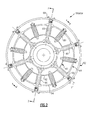
- the turbine section 28 generally includes static case structure 36MTF which is disclosed herein as a mid-turbine section of the gas turbine engine 20.
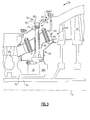
- the static structure 36MTF includes an annular inner turbine exhaust case 60, an annular outer turbine exhaust case 62, a mid-turbine frame (MTF) 64, a multiple of support tie rods 66, a respective multiple of tie rod nuts 68 and a multiple of spring biased tie-rod assemblies 80 ( Figures 3 and 4 ).
- the annular inner turbine exhaust case 60 typically supports a bearing system 38 as well as other components such as seal cartridge structures 38S within which the inner and outer shafts 40, 50 rotate.
- the support tie rods 66 are utilized to mount the mid-turbine frame 64 within the annular inner turbine exhaust case 60 and the annular outer turbine exhaust case 62.
- Each of the support tie rods 66 may be fastened to the annular inner turbine exhaust case 60 through a multiple of fasteners 70 such that the annular outer turbine exhaust case 62 is spaced relative thereto.
- Each of the support tie rods 66 are fastened to the annular outer turbine exhaust case 62 by the respective tie rod nut 68 which is threaded via an inner diameter thread 72 to an outer diameter thread 74 of an end section 76 of each support tie rod 66.
- Each tie rod nut 68 is then secured to the annular outer turbine exhaust case 62 with one or more fasteners 78 which extend thru holes 79 in the tie rod nut 68 as generally understood. It should be understood that various attachment arrangements may alternatively or additionally be utilized.
- the mid-turbine frame (MTF) 64 generally includes a multiple of airfoils 90, an inner ring 92, and an outer ring 94 manufactured of a ceramic matrix composite (CMC) material typically in a ring-strut ring full hoop structure.
- CMC ceramic matrix composite
- the inner ring 92 and the outer ring 94 utilize the hoop strength characteristics of the CMC to form a full hoop shroud in a ring-strut-ring structure.
- the term full hoop is defined herein as an uninterrupted member which surround the airfoils. It should be appreciated that examples of CMC material for componentry discussed herein may include, but are not limited to, for example, S200 and SiC/SiC.
- mid-turbine frame (MTF) 64 in the disclosed embodiment, it should also be understood that the concepts described herein may be applied to other sections such as high pressure turbines, high pressure compressors, low pressure compressors, as well as intermediate pressure turbines and intermediate pressure compressors of a three-spool architecture gas turbine engine.
- MTF mid-turbine frame
- each airfoil 90 generally includes an airfoil portion 96 with a generally concave shaped portion which forms a pressure side 102 and a generally convex shaped portion which forms a suction side 104 between a leading edge 98 and a trailing edge 100.
- Each airfoil portion 96 may include a fillet section 106, 108 to provide a transition between the airfoil portion 96 and a platform segment 110, 112.
- the platform segment 110, 112 may include unidirectional plys which are aligned tows with or without weave, as well as additional or alternative fabric plies to obtain a thicker platform segment if so required.
- the platform segment 110, 112 are surrounded by the inner ring 92 and the outer ring 94.
- either or both of the platform segments segment 110, 112 may be of a circumferential complementary geometry such as a chevron-shape to provide a complementary abutting edge engagement for each adjacent platform segment to define the inner and outer core gas path. That is, the airfoil 90 are assembled in an adjacent complementary manner with the respectively adjacent platform segments 110, 112 to form a full hoop unitary structure to form a ring of airfoils which are then surrounded by the inner ring 92 and outer ring 94 ( Figures 3 and 4 ).
- the pressure side 102 and the suction side 104 may be formed from a respective multiple of CMC plies formed around or along a pressure vessel 118 and an insert 120. That is, the pressure vessel 118 and the insert 120 provide internal support structure within the airfoil portion 96. This internal support structure may be located in each or only some of the airfoil portions 96.
- the pressure vessel 118 may be formed as a monolithic ceramic material such as a silicon carbide, silicon nitride or alternatively from a multiple of CMC plies which are wrapped to form a hollow tube in cross-section.
- the pressure vessel 118 strengthens the CMC airfoil 90 to resist the differential pressure generated between the core flow along the airfoil portion 96 and the secondary cooling flow which may be communicated through the airfoil portion 96.
- other passages may be formed through the mid-turbine frame (MTF) 64 separate from the airfoils 90 to provide a path for wire harnesses, conduits, or other systems.
- MTF mid-turbine frame
- the insert 120 may also be formed as a monolithic or a multiple of CMC plies to define an aperture 122 to receive the spring biased tie-rod assemblies 80 ( Figure 6 ) which apply a compressive force to the mid-turbine frame (MTF) 64. That is, the insert 120 operates to reinforce the airfoil portion 96 and react the compressive force generated by the spring biased tie-rod assemblies 80. It should be appreciated that the spring biased tie-rod assembly 80 may be oriented in an opposite or alternative direction.
- each of the spring biased tie-rod assemblies 80 generally include a tie rod 124, a split retainer 126A, 126B, a spring seat 128, 130, and a spring 132.
- the tie rod 124 may be manufactured of monolithic ceramic material with flared end sections 134A, 134B which may be frustro-conical.
- the tie-rod 124 may alternatively be formed of a tow which is a collection of fibers such as a silicon based fiber, a uni-tape, or cloth that is formed as a tube or rod along a longitudinal axis T of the tie-rod 124.
- the tie rod 124 mounts through the insert 120 along a longitudinal axis T.
- the split retainer 126A, 126B and the spring seat 128, 130 may be manufactured of a low thermal conductivity material such as the monolithic ceramic materials.
- the end sections 134A, 134B interface with the split retainers 126A, 126B (also shown in Figures 7 and 8 ).
- the split ring 126B and the spring seat 128 are received within a reinforced pocket 136A, 136B formed in the respective outer ring 94 and inner ring 92.
- the reinforced pocket 136 may be formed by a localized ply buildup that may be, for example between 1.5- 2 times the nominal thickness of the outer ring 94.
- the split retainer 126A abuts the flared end section of the spring seat 130 and is thereby trapped therein.
- the spring seat 128 is also received within a respective reinforced pocket 136B formed in the outer ring 94 which may also be formed by a localized ply buildup similar to that of the inner ring 92.
- the spring seat 128, 130 are formed as full rings.
- the spring 132 is captured by the spring seats 128, 130 to maintain the split retainer 126A together to generate a tension along the axis T.
- the tension along the tie rod 124 thereby maintains the mid-turbine frame (MTF) 64 in compression and to essentially clamp the CMC airfoils 90 between the CMC inner ring 92 and the CMC outer ring 94.
- the spring 132 creates a preload on the tie-rod 124 so that it is always in tension.
- the MTF assembly therefore, is always in compression, regardless of the thermal expansion and pressure loads.
- Such compression reduces the potential for delamination and minimize the stress riser associated with the displaced layers as plys in compression, or otherwise constrained, are less likely to delaminate at a given load.
- the compression also reduces the leakage between the airfoil and the inner and outer rings.
- a large axial pressure load typically exists across the mid-turbine case due to higher pressure upstream in the high pressure turbine 54 (HPT) versus the lower pressures downstream in the low pressure turbine 46 (LPT).
- the spring biased tie-rod assemblies 80 provide a truss like structure that more effectively resists this load (and reduces axial deflection). Reductions in the axial deflection limits as well as provision of a unitary mid-turbine frame (MTF) 64 facilitates centering of the bearing rolling elements on their races in the bearing systems 38 as well as provide a leak-proof annular structure. It should be understood that only a few support tie rods 66 may be required as compared to the spring biased tie rod assemblies 80 which may be located in each and every CMC airfoil 90. That is, some CMC airfoils 90 may include both a support tie rod 66 and a spring biased tie rod assembly 80.
Landscapes
- Engineering & Computer Science (AREA)
- Mechanical Engineering (AREA)
- General Engineering & Computer Science (AREA)
- Turbine Rotor Nozzle Sealing (AREA)
Applications Claiming Priority (1)
| Application Number | Priority Date | Filing Date | Title |
|---|---|---|---|
| US13/275,276 US9200536B2 (en) | 2011-10-17 | 2011-10-17 | Mid turbine frame (MTF) for a gas turbine engine |
Publications (3)
| Publication Number | Publication Date |
|---|---|
| EP2584152A2 true EP2584152A2 (fr) | 2013-04-24 |
| EP2584152A3 EP2584152A3 (fr) | 2016-11-02 |
| EP2584152B1 EP2584152B1 (fr) | 2019-04-17 |
Family
ID=47080286
Family Applications (1)
| Application Number | Title | Priority Date | Filing Date |
|---|---|---|---|
| EP12187969.6A Active EP2584152B1 (fr) | 2011-10-17 | 2012-10-10 | Cadre de turbine intermédiaire (MTF) pour un moteur à turbine à gaz |
Country Status (2)
| Country | Link |
|---|---|
| US (2) | US9200536B2 (fr) |
| EP (1) | EP2584152B1 (fr) |
Cited By (8)
| Publication number | Priority date | Publication date | Assignee | Title |
|---|---|---|---|---|
| EP3009601A1 (fr) * | 2014-09-30 | 2016-04-20 | United Technologies Corporation | Ensemble d'aube avec entretoise et tirant |
| EP3081761A1 (fr) * | 2015-04-13 | 2016-10-19 | United Technologies Corporation | Module interturbine et turbine à gaz avec un module interturbine |
| EP2959119A4 (fr) * | 2013-02-22 | 2016-10-26 | Structure de fixation de moteur de turbine à gaz et procédé associé | |
| US20160341054A1 (en) * | 2014-02-03 | 2016-11-24 | United Technologies Corporation | Gas turbine engine cooling fluid composite tube |
| EP3208433A1 (fr) * | 2016-02-22 | 2017-08-23 | MTU Aero Engines GmbH | Carter intermédiaire de turbine et système d'étancheification en matière composite en fibres à céramique |
| US20180328230A1 (en) * | 2015-08-31 | 2018-11-15 | Kawasaki Jukogyo Kabushiki Kaisha | Exhaust diffuser |
| US10947864B2 (en) * | 2016-09-12 | 2021-03-16 | Siemens Energy Global GmbH & Co. KG | Gas turbine with separate cooling for turbine and exhaust casing |
| FR3108673A1 (fr) * | 2020-03-27 | 2021-10-01 | Safran Aircraft Engines | Turbine de turbomachine a distributeur en cmc avec panachage de mats pleins a la couronne |
Families Citing this family (45)
| Publication number | Priority date | Publication date | Assignee | Title |
|---|---|---|---|---|
| US20140003920A1 (en) * | 2012-07-02 | 2014-01-02 | United Technologies Corporation | Flow metering anti-rotation outer diameter (od) hex nut |
| US9217371B2 (en) * | 2012-07-13 | 2015-12-22 | United Technologies Corporation | Mid-turbine frame with tensioned spokes |
| US9222413B2 (en) * | 2012-07-13 | 2015-12-29 | United Technologies Corporation | Mid-turbine frame with threaded spokes |
| US9482115B2 (en) * | 2012-08-23 | 2016-11-01 | United Technologies Corporation | Turbine engine support assembly including self anti-rotating bushing |
| US9945411B2 (en) * | 2012-08-31 | 2018-04-17 | United Technologies Corporation | Self-anti-rotating dual lock washer |
| WO2014137574A1 (fr) * | 2013-03-05 | 2014-09-12 | United Technologies Corporation | Tige de carter de turbine intermédiaire et collerette de carter de turbine |
| WO2015069358A2 (fr) | 2013-09-11 | 2015-05-14 | United Technologies Corporation | Revêtement céramique pour carter de sortie de turbine |
| CA2944563C (fr) | 2014-04-11 | 2018-11-20 | General Electric Company | Ensemble de carenage de cadre central de turbine |
| US20160201512A1 (en) * | 2015-01-09 | 2016-07-14 | United Technologies Corporation | Gas turbine engine mid-turbine frame tie rod arrangement |
| US9790860B2 (en) | 2015-01-16 | 2017-10-17 | United Technologies Corporation | Cooling passages for a mid-turbine frame |
| US9915171B2 (en) | 2015-01-16 | 2018-03-13 | United Technologies Corporation | Cooling passages for a mid-turbine frame |
| US10371010B2 (en) | 2015-01-16 | 2019-08-06 | United Technologies Corporation | Tie rod for a mid-turbine frame |
| US10309308B2 (en) * | 2015-01-16 | 2019-06-04 | United Technologies Corporation | Cooling passages for a mid-turbine frame |
| US9920651B2 (en) | 2015-01-16 | 2018-03-20 | United Technologies Corporation | Cooling passages for a mid-turbine frame |
| US9856750B2 (en) | 2015-01-16 | 2018-01-02 | United Technologies Corporation | Cooling passages for a mid-turbine frame |
| US9995171B2 (en) | 2015-01-16 | 2018-06-12 | United Technologies Corporation | Cooling passages for a mid-turbine frame |
| US10392974B2 (en) | 2015-02-03 | 2019-08-27 | United Technologies Corporation | Mid-turbine frame assembly |
| US10655482B2 (en) | 2015-02-05 | 2020-05-19 | Rolls-Royce Corporation | Vane assemblies for gas turbine engines |
| US9803502B2 (en) | 2015-02-09 | 2017-10-31 | United Technologies Corporation | Cooling passages for a mid-turbine frame |
| US10087785B2 (en) | 2015-02-09 | 2018-10-02 | United Technologies Corporation | Mid-turbine frame assembly for a gas turbine engine |
| US9951624B2 (en) | 2015-02-09 | 2018-04-24 | United Technologies Corporation | Clinch nut bolt hole geometry |
| US9879604B2 (en) | 2015-03-11 | 2018-01-30 | United Technologies Corporation | Cooling passages for a mid-turbine frame |
| US9732628B2 (en) | 2015-03-20 | 2017-08-15 | United Technologies Corporation | Cooling passages for a mid-turbine frame |
| US9915170B2 (en) * | 2015-03-20 | 2018-03-13 | United Technologies Corporation | Cooling passages for a mid-turbine frame |
| US9885254B2 (en) | 2015-04-24 | 2018-02-06 | United Technologies Corporation | Mid turbine frame including a sealed torque box |
| US10247035B2 (en) | 2015-07-24 | 2019-04-02 | Pratt & Whitney Canada Corp. | Spoke locking architecture |
| CA2936180C (fr) | 2015-07-24 | 2025-05-06 | Pratt & Whitney Canada Corp. | Système et procédé de refroidissement à plusieurs rayons |
| US10443449B2 (en) | 2015-07-24 | 2019-10-15 | Pratt & Whitney Canada Corp. | Spoke mounting arrangement |
| EP3141702A1 (fr) * | 2015-09-14 | 2017-03-15 | Siemens Aktiengesellschaft | Segment d'aube directrice de turbine à gaz et procédé de fabrication |
| US10443415B2 (en) * | 2016-03-30 | 2019-10-15 | General Electric Company | Flowpath assembly for a gas turbine engine |
| ES2769074T3 (es) * | 2017-06-01 | 2020-06-24 | MTU Aero Engines AG | Carcasa intermedia para turbina con elemento de centrado |
| US10598046B2 (en) * | 2018-07-11 | 2020-03-24 | United Technologies Corporation | Support straps and method of assembly for gas turbine engine |
| US10767497B2 (en) * | 2018-09-07 | 2020-09-08 | Rolls-Royce Corporation | Turbine vane assembly with ceramic matrix composite components |
| DE102018132892A1 (de) * | 2018-12-19 | 2020-06-25 | Rolls-Royce Deutschland Ltd & Co Kg | Zwischengehäusestruktur für eine Verdichtervorrichtung eines Gasturbinentriebwerks und ein Gasturbinentriebwerk |
| US10941669B2 (en) * | 2018-12-21 | 2021-03-09 | Raytheon Technologies Corporation | Diffuser case support structure |
| US10823011B2 (en) | 2019-02-07 | 2020-11-03 | Raytheon Technologies Corporation | Turbine engine tie rod systems |
| US10954802B2 (en) * | 2019-04-23 | 2021-03-23 | Rolls-Royce Plc | Turbine section assembly with ceramic matrix composite vane |
| US11008880B2 (en) * | 2019-04-23 | 2021-05-18 | Rolls-Royce Plc | Turbine section assembly with ceramic matrix composite vane |
| FR3097264B1 (fr) * | 2019-06-12 | 2021-05-28 | Safran Aircraft Engines | Turbine de turbomachine à distributeur en CMC avec reprise d’effort |
| US11242762B2 (en) * | 2019-11-21 | 2022-02-08 | Raytheon Technologies Corporation | Vane with collar |
| US11492733B2 (en) * | 2020-02-21 | 2022-11-08 | Raytheon Technologies Corporation | Weave control grid |
| KR102367002B1 (ko) | 2020-08-28 | 2022-02-23 | 두산중공업 주식회사 | 타이로드의 인장 조립구조와 이를 포함하는 가스 터빈 및 타이로드의 인장 조립방법 |
| US11719130B2 (en) | 2021-05-06 | 2023-08-08 | Raytheon Technologies Corporation | Vane system with continuous support ring |
| US11913348B1 (en) * | 2022-10-12 | 2024-02-27 | Rtx Corporation | Gas turbine engine vane and spar combination with variable air flow path |
| US20260063049A1 (en) * | 2024-08-29 | 2026-03-05 | Rtx Corporation | Fan exit guide vane load carrying tension member with damper |
Family Cites Families (20)
| Publication number | Priority date | Publication date | Assignee | Title |
|---|---|---|---|---|
| US3558237A (en) * | 1969-06-25 | 1971-01-26 | Gen Motors Corp | Variable turbine nozzles |
| US4645415A (en) * | 1983-12-23 | 1987-02-24 | United Technologies Corporation | Air cooler for providing buffer air to a bearing compartment |
| US4987736A (en) * | 1988-12-14 | 1991-01-29 | General Electric Company | Lightweight gas turbine engine frame with free-floating heat shield |
| US5511940A (en) * | 1995-01-06 | 1996-04-30 | Solar Turbines Incorporated | Ceramic turbine nozzle |
| US6000906A (en) * | 1997-09-12 | 1999-12-14 | Alliedsignal Inc. | Ceramic airfoil |
| US7093359B2 (en) | 2002-09-17 | 2006-08-22 | Siemens Westinghouse Power Corporation | Composite structure formed by CMC-on-insulation process |
| US7094021B2 (en) * | 2004-02-02 | 2006-08-22 | General Electric Company | Gas turbine flowpath structure |
| US7153096B2 (en) * | 2004-12-02 | 2006-12-26 | Siemens Power Generation, Inc. | Stacked laminate CMC turbine vane |
| US7452182B2 (en) * | 2005-04-07 | 2008-11-18 | Siemens Energy, Inc. | Multi-piece turbine vane assembly |
| US7510371B2 (en) * | 2005-06-06 | 2009-03-31 | General Electric Company | Forward tilted turbine nozzle |
| US7874059B2 (en) * | 2006-01-12 | 2011-01-25 | Siemens Energy, Inc. | Attachment for ceramic matrix composite component |
| US20080060755A1 (en) | 2006-09-13 | 2008-03-13 | General Electric Corporation | composite corner and method for making composite corner |
| US7753643B2 (en) * | 2006-09-22 | 2010-07-13 | Siemens Energy, Inc. | Stacked laminate bolted ring segment |
| US7600979B2 (en) * | 2006-11-28 | 2009-10-13 | General Electric Company | CMC articles having small complex features |
| US7824151B2 (en) | 2006-12-06 | 2010-11-02 | United Technologies Corporation | Zero running clearance centrifugal compressor |
| US7824152B2 (en) * | 2007-05-09 | 2010-11-02 | Siemens Energy, Inc. | Multivane segment mounting arrangement for a gas turbine |
| US8292580B2 (en) | 2008-09-18 | 2012-10-23 | Siemens Energy, Inc. | CMC vane assembly apparatus and method |
| US8251651B2 (en) | 2009-01-28 | 2012-08-28 | United Technologies Corporation | Segmented ceramic matrix composite turbine airfoil component |
| US20100200189A1 (en) * | 2009-02-12 | 2010-08-12 | General Electric Company | Method of fabricating turbine airfoils and tip structures therefor |
| US8371127B2 (en) * | 2009-10-01 | 2013-02-12 | Pratt & Whitney Canada Corp. | Cooling air system for mid turbine frame |
-
2011
- 2011-10-17 US US13/275,276 patent/US9200536B2/en not_active Expired - Fee Related
-
2012
- 2012-10-10 EP EP12187969.6A patent/EP2584152B1/fr active Active
-
2015
- 2015-09-08 US US14/847,363 patent/US10036281B2/en active Active
Non-Patent Citations (1)
| Title |
|---|
| None |
Cited By (16)
| Publication number | Priority date | Publication date | Assignee | Title |
|---|---|---|---|---|
| EP2959119A4 (fr) * | 2013-02-22 | 2016-10-26 | Structure de fixation de moteur de turbine à gaz et procédé associé | |
| US10774687B2 (en) | 2013-02-22 | 2020-09-15 | Raytheon Technologies Corporation | Gas turbine engine attachment structure and method therefor |
| US10151218B2 (en) | 2013-02-22 | 2018-12-11 | United Technologies Corporation | Gas turbine engine attachment structure and method therefor |
| US10662792B2 (en) * | 2014-02-03 | 2020-05-26 | Raytheon Technologies Corporation | Gas turbine engine cooling fluid composite tube |
| US20160341054A1 (en) * | 2014-02-03 | 2016-11-24 | United Technologies Corporation | Gas turbine engine cooling fluid composite tube |
| EP3102808A4 (fr) * | 2014-02-03 | 2017-09-06 | United Technologies Corporation | Tube composite de liquide de refroidissement d'un moteur à turbine à gaz |
| US10107117B2 (en) | 2014-09-30 | 2018-10-23 | United Technologies Corporation | Airfoil assembly with spacer and tie-spar |
| EP3009601A1 (fr) * | 2014-09-30 | 2016-04-20 | United Technologies Corporation | Ensemble d'aube avec entretoise et tirant |
| US10465540B2 (en) | 2014-09-30 | 2019-11-05 | United Technologies Corporation | Airfoil assembly with spacer and tie-spar |
| EP3081761A1 (fr) * | 2015-04-13 | 2016-10-19 | United Technologies Corporation | Module interturbine et turbine à gaz avec un module interturbine |
| US9771829B2 (en) | 2015-04-13 | 2017-09-26 | United Technologies Corporation | Cutouts in gas turbine structures for deflection control |
| US20180328230A1 (en) * | 2015-08-31 | 2018-11-15 | Kawasaki Jukogyo Kabushiki Kaisha | Exhaust diffuser |
| US10851676B2 (en) * | 2015-08-31 | 2020-12-01 | Kawasaki Jukogyo Kabushiki Kaisha | Exhaust diffuser |
| EP3208433A1 (fr) * | 2016-02-22 | 2017-08-23 | MTU Aero Engines GmbH | Carter intermédiaire de turbine et système d'étancheification en matière composite en fibres à céramique |
| US10947864B2 (en) * | 2016-09-12 | 2021-03-16 | Siemens Energy Global GmbH & Co. KG | Gas turbine with separate cooling for turbine and exhaust casing |
| FR3108673A1 (fr) * | 2020-03-27 | 2021-10-01 | Safran Aircraft Engines | Turbine de turbomachine a distributeur en cmc avec panachage de mats pleins a la couronne |
Also Published As
| Publication number | Publication date |
|---|---|
| EP2584152B1 (fr) | 2019-04-17 |
| US10036281B2 (en) | 2018-07-31 |
| EP2584152A3 (fr) | 2016-11-02 |
| US20130094951A1 (en) | 2013-04-18 |
| US20150377067A1 (en) | 2015-12-31 |
| US9200536B2 (en) | 2015-12-01 |
Similar Documents
| Publication | Publication Date | Title |
|---|---|---|
| EP2584152B1 (fr) | Cadre de turbine intermédiaire (MTF) pour un moteur à turbine à gaz | |
| EP2565395B1 (fr) | Barre d'accouplement pour moteur à turbine à gaz | |
| US9335051B2 (en) | Ceramic matrix composite combustor vane ring assembly | |
| US8967961B2 (en) | Ceramic matrix composite airfoil structure with trailing edge support for a gas turbine engine | |
| US9194252B2 (en) | Turbine frame fairing for a gas turbine engine | |
| US10184402B2 (en) | Ceramic matrix composite turbine exhaust case for a gas turbine engine | |
| US11732597B2 (en) | Double box composite seal assembly with insert for gas turbine engine | |
| US12158087B2 (en) | Fairing assembly | |
| EP3913197A1 (fr) | Assemblages pour le transfert des charges de compression dans les brides des composants composites de moteur de turbine à gaz | |
| US11359507B2 (en) | Double box composite seal assembly with fiber density arrangement for gas turbine engine | |
| EP3263841B1 (fr) | Bossage de carter de turbine | |
| EP3543479A1 (fr) | Ensemble de support de palier flottant | |
| US20150377073A1 (en) | Titanium aluminide turbine exhaust structure | |
| US12258881B2 (en) | Turbine section with ceramic support rings and ceramic vane arc segments |
Legal Events
| Date | Code | Title | Description |
|---|---|---|---|
| PUAI | Public reference made under article 153(3) epc to a published international application that has entered the european phase |
Free format text: ORIGINAL CODE: 0009012 |
|
| AK | Designated contracting states |
Kind code of ref document: A2 Designated state(s): AL AT BE BG CH CY CZ DE DK EE ES FI FR GB GR HR HU IE IS IT LI LT LU LV MC MK MT NL NO PL PT RO RS SE SI SK SM TR |
|
| AX | Request for extension of the european patent |
Extension state: BA ME |
|
| PUAL | Search report despatched |
Free format text: ORIGINAL CODE: 0009013 |
|
| RAP1 | Party data changed (applicant data changed or rights of an application transferred) |
Owner name: UNITED TECHNOLOGIES CORPORATION |
|
| AK | Designated contracting states |
Kind code of ref document: A3 Designated state(s): AL AT BE BG CH CY CZ DE DK EE ES FI FR GB GR HR HU IE IS IT LI LT LU LV MC MK MT NL NO PL PT RO RS SE SI SK SM TR |
|
| AX | Request for extension of the european patent |
Extension state: BA ME |
|
| RIC1 | Information provided on ipc code assigned before grant |
Ipc: F01D 9/04 20060101ALI20160923BHEP Ipc: F01D 25/16 20060101AFI20160923BHEP |
|
| STAA | Information on the status of an ep patent application or granted ep patent |
Free format text: STATUS: REQUEST FOR EXAMINATION WAS MADE |
|
| 17P | Request for examination filed |
Effective date: 20170502 |
|
| RBV | Designated contracting states (corrected) |
Designated state(s): AL AT BE BG CH CY CZ DE DK EE ES FI FR GB GR HR HU IE IS IT LI LT LU LV MC MK MT NL NO PL PT RO RS SE SI SK SM TR |
|
| GRAP | Despatch of communication of intention to grant a patent |
Free format text: ORIGINAL CODE: EPIDOSNIGR1 |
|
| STAA | Information on the status of an ep patent application or granted ep patent |
Free format text: STATUS: GRANT OF PATENT IS INTENDED |
|
| RIC1 | Information provided on ipc code assigned before grant |
Ipc: F01D 9/04 20060101ALI20181010BHEP Ipc: F01D 25/16 20060101AFI20181010BHEP |
|
| INTG | Intention to grant announced |
Effective date: 20181029 |
|
| GRAS | Grant fee paid |
Free format text: ORIGINAL CODE: EPIDOSNIGR3 |
|
| GRAA | (expected) grant |
Free format text: ORIGINAL CODE: 0009210 |
|
| STAA | Information on the status of an ep patent application or granted ep patent |
Free format text: STATUS: THE PATENT HAS BEEN GRANTED |
|
| AK | Designated contracting states |
Kind code of ref document: B1 Designated state(s): AL AT BE BG CH CY CZ DE DK EE ES FI FR GB GR HR HU IE IS IT LI LT LU LV MC MK MT NL NO PL PT RO RS SE SI SK SM TR |
|
| REG | Reference to a national code |
Ref country code: GB Ref legal event code: FG4D |
|
| REG | Reference to a national code |
Ref country code: CH Ref legal event code: EP |
|
| REG | Reference to a national code |
Ref country code: DE Ref legal event code: R096 Ref document number: 602012059037 Country of ref document: DE |
|
| REG | Reference to a national code |
Ref country code: AT Ref legal event code: REF Ref document number: 1121777 Country of ref document: AT Kind code of ref document: T Effective date: 20190515 Ref country code: IE Ref legal event code: FG4D |
|
| REG | Reference to a national code |
Ref country code: NL Ref legal event code: MP Effective date: 20190417 |
|
| REG | Reference to a national code |
Ref country code: LT Ref legal event code: MG4D |
|
| PG25 | Lapsed in a contracting state [announced via postgrant information from national office to epo] |
Ref country code: NL Free format text: LAPSE BECAUSE OF FAILURE TO SUBMIT A TRANSLATION OF THE DESCRIPTION OR TO PAY THE FEE WITHIN THE PRESCRIBED TIME-LIMIT Effective date: 20190417 |
|
| PG25 | Lapsed in a contracting state [announced via postgrant information from national office to epo] |
Ref country code: NO Free format text: LAPSE BECAUSE OF FAILURE TO SUBMIT A TRANSLATION OF THE DESCRIPTION OR TO PAY THE FEE WITHIN THE PRESCRIBED TIME-LIMIT Effective date: 20190717 Ref country code: HR Free format text: LAPSE BECAUSE OF FAILURE TO SUBMIT A TRANSLATION OF THE DESCRIPTION OR TO PAY THE FEE WITHIN THE PRESCRIBED TIME-LIMIT Effective date: 20190417 Ref country code: LT Free format text: LAPSE BECAUSE OF FAILURE TO SUBMIT A TRANSLATION OF THE DESCRIPTION OR TO PAY THE FEE WITHIN THE PRESCRIBED TIME-LIMIT Effective date: 20190417 Ref country code: ES Free format text: LAPSE BECAUSE OF FAILURE TO SUBMIT A TRANSLATION OF THE DESCRIPTION OR TO PAY THE FEE WITHIN THE PRESCRIBED TIME-LIMIT Effective date: 20190417 Ref country code: PT Free format text: LAPSE BECAUSE OF FAILURE TO SUBMIT A TRANSLATION OF THE DESCRIPTION OR TO PAY THE FEE WITHIN THE PRESCRIBED TIME-LIMIT Effective date: 20190817 Ref country code: AL Free format text: LAPSE BECAUSE OF FAILURE TO SUBMIT A TRANSLATION OF THE DESCRIPTION OR TO PAY THE FEE WITHIN THE PRESCRIBED TIME-LIMIT Effective date: 20190417 Ref country code: SE Free format text: LAPSE BECAUSE OF FAILURE TO SUBMIT A TRANSLATION OF THE DESCRIPTION OR TO PAY THE FEE WITHIN THE PRESCRIBED TIME-LIMIT Effective date: 20190417 Ref country code: FI Free format text: LAPSE BECAUSE OF FAILURE TO SUBMIT A TRANSLATION OF THE DESCRIPTION OR TO PAY THE FEE WITHIN THE PRESCRIBED TIME-LIMIT Effective date: 20190417 |
|
| PG25 | Lapsed in a contracting state [announced via postgrant information from national office to epo] |
Ref country code: LV Free format text: LAPSE BECAUSE OF FAILURE TO SUBMIT A TRANSLATION OF THE DESCRIPTION OR TO PAY THE FEE WITHIN THE PRESCRIBED TIME-LIMIT Effective date: 20190417 Ref country code: GR Free format text: LAPSE BECAUSE OF FAILURE TO SUBMIT A TRANSLATION OF THE DESCRIPTION OR TO PAY THE FEE WITHIN THE PRESCRIBED TIME-LIMIT Effective date: 20190718 Ref country code: PL Free format text: LAPSE BECAUSE OF FAILURE TO SUBMIT A TRANSLATION OF THE DESCRIPTION OR TO PAY THE FEE WITHIN THE PRESCRIBED TIME-LIMIT Effective date: 20190417 Ref country code: RS Free format text: LAPSE BECAUSE OF FAILURE TO SUBMIT A TRANSLATION OF THE DESCRIPTION OR TO PAY THE FEE WITHIN THE PRESCRIBED TIME-LIMIT Effective date: 20190417 Ref country code: BG Free format text: LAPSE BECAUSE OF FAILURE TO SUBMIT A TRANSLATION OF THE DESCRIPTION OR TO PAY THE FEE WITHIN THE PRESCRIBED TIME-LIMIT Effective date: 20190717 |
|
| REG | Reference to a national code |
Ref country code: AT Ref legal event code: MK05 Ref document number: 1121777 Country of ref document: AT Kind code of ref document: T Effective date: 20190417 |
|
| PG25 | Lapsed in a contracting state [announced via postgrant information from national office to epo] |
Ref country code: IS Free format text: LAPSE BECAUSE OF FAILURE TO SUBMIT A TRANSLATION OF THE DESCRIPTION OR TO PAY THE FEE WITHIN THE PRESCRIBED TIME-LIMIT Effective date: 20190817 |
|
| REG | Reference to a national code |
Ref country code: DE Ref legal event code: R097 Ref document number: 602012059037 Country of ref document: DE |
|
| PG25 | Lapsed in a contracting state [announced via postgrant information from national office to epo] |
Ref country code: SK Free format text: LAPSE BECAUSE OF FAILURE TO SUBMIT A TRANSLATION OF THE DESCRIPTION OR TO PAY THE FEE WITHIN THE PRESCRIBED TIME-LIMIT Effective date: 20190417 Ref country code: RO Free format text: LAPSE BECAUSE OF FAILURE TO SUBMIT A TRANSLATION OF THE DESCRIPTION OR TO PAY THE FEE WITHIN THE PRESCRIBED TIME-LIMIT Effective date: 20190417 Ref country code: CZ Free format text: LAPSE BECAUSE OF FAILURE TO SUBMIT A TRANSLATION OF THE DESCRIPTION OR TO PAY THE FEE WITHIN THE PRESCRIBED TIME-LIMIT Effective date: 20190417 Ref country code: EE Free format text: LAPSE BECAUSE OF FAILURE TO SUBMIT A TRANSLATION OF THE DESCRIPTION OR TO PAY THE FEE WITHIN THE PRESCRIBED TIME-LIMIT Effective date: 20190417 Ref country code: DK Free format text: LAPSE BECAUSE OF FAILURE TO SUBMIT A TRANSLATION OF THE DESCRIPTION OR TO PAY THE FEE WITHIN THE PRESCRIBED TIME-LIMIT Effective date: 20190417 Ref country code: AT Free format text: LAPSE BECAUSE OF FAILURE TO SUBMIT A TRANSLATION OF THE DESCRIPTION OR TO PAY THE FEE WITHIN THE PRESCRIBED TIME-LIMIT Effective date: 20190417 |
|
| PLBE | No opposition filed within time limit |
Free format text: ORIGINAL CODE: 0009261 |
|
| STAA | Information on the status of an ep patent application or granted ep patent |
Free format text: STATUS: NO OPPOSITION FILED WITHIN TIME LIMIT |
|
| PG25 | Lapsed in a contracting state [announced via postgrant information from national office to epo] |
Ref country code: IT Free format text: LAPSE BECAUSE OF FAILURE TO SUBMIT A TRANSLATION OF THE DESCRIPTION OR TO PAY THE FEE WITHIN THE PRESCRIBED TIME-LIMIT Effective date: 20190417 Ref country code: SM Free format text: LAPSE BECAUSE OF FAILURE TO SUBMIT A TRANSLATION OF THE DESCRIPTION OR TO PAY THE FEE WITHIN THE PRESCRIBED TIME-LIMIT Effective date: 20190417 |
|
| 26N | No opposition filed |
Effective date: 20200120 |
|
| PG25 | Lapsed in a contracting state [announced via postgrant information from national office to epo] |
Ref country code: TR Free format text: LAPSE BECAUSE OF FAILURE TO SUBMIT A TRANSLATION OF THE DESCRIPTION OR TO PAY THE FEE WITHIN THE PRESCRIBED TIME-LIMIT Effective date: 20190417 |
|
| PG25 | Lapsed in a contracting state [announced via postgrant information from national office to epo] |
Ref country code: MC Free format text: LAPSE BECAUSE OF FAILURE TO SUBMIT A TRANSLATION OF THE DESCRIPTION OR TO PAY THE FEE WITHIN THE PRESCRIBED TIME-LIMIT Effective date: 20190417 Ref country code: SI Free format text: LAPSE BECAUSE OF FAILURE TO SUBMIT A TRANSLATION OF THE DESCRIPTION OR TO PAY THE FEE WITHIN THE PRESCRIBED TIME-LIMIT Effective date: 20190417 |
|
| REG | Reference to a national code |
Ref country code: CH Ref legal event code: PL |
|
| PG25 | Lapsed in a contracting state [announced via postgrant information from national office to epo] |
Ref country code: LU Free format text: LAPSE BECAUSE OF NON-PAYMENT OF DUE FEES Effective date: 20191010 Ref country code: LI Free format text: LAPSE BECAUSE OF NON-PAYMENT OF DUE FEES Effective date: 20191031 Ref country code: CH Free format text: LAPSE BECAUSE OF NON-PAYMENT OF DUE FEES Effective date: 20191031 |
|
| REG | Reference to a national code |
Ref country code: BE Ref legal event code: MM Effective date: 20191031 |
|
| PG25 | Lapsed in a contracting state [announced via postgrant information from national office to epo] |
Ref country code: BE Free format text: LAPSE BECAUSE OF NON-PAYMENT OF DUE FEES Effective date: 20191031 |
|
| PG25 | Lapsed in a contracting state [announced via postgrant information from national office to epo] |
Ref country code: IE Free format text: LAPSE BECAUSE OF NON-PAYMENT OF DUE FEES Effective date: 20191010 |
|
| PG25 | Lapsed in a contracting state [announced via postgrant information from national office to epo] |
Ref country code: CY Free format text: LAPSE BECAUSE OF FAILURE TO SUBMIT A TRANSLATION OF THE DESCRIPTION OR TO PAY THE FEE WITHIN THE PRESCRIBED TIME-LIMIT Effective date: 20190417 |
|
| PG25 | Lapsed in a contracting state [announced via postgrant information from national office to epo] |
Ref country code: HU Free format text: LAPSE BECAUSE OF FAILURE TO SUBMIT A TRANSLATION OF THE DESCRIPTION OR TO PAY THE FEE WITHIN THE PRESCRIBED TIME-LIMIT; INVALID AB INITIO Effective date: 20121010 Ref country code: MT Free format text: LAPSE BECAUSE OF FAILURE TO SUBMIT A TRANSLATION OF THE DESCRIPTION OR TO PAY THE FEE WITHIN THE PRESCRIBED TIME-LIMIT Effective date: 20190417 |
|
| PG25 | Lapsed in a contracting state [announced via postgrant information from national office to epo] |
Ref country code: MK Free format text: LAPSE BECAUSE OF FAILURE TO SUBMIT A TRANSLATION OF THE DESCRIPTION OR TO PAY THE FEE WITHIN THE PRESCRIBED TIME-LIMIT Effective date: 20190417 |
|
| REG | Reference to a national code |
Ref country code: DE Ref legal event code: R081 Ref document number: 602012059037 Country of ref document: DE Owner name: RAYTHEON TECHNOLOGIES CORPORATION (N.D.GES.D.S, US Free format text: FORMER OWNER: UNITED TECHNOLOGIES CORPORATION, FARMINGTON, CONN., US Ref country code: DE Ref legal event code: R081 Ref document number: 602012059037 Country of ref document: DE Owner name: RTX CORPORATION (N.D.GES.D. STAATES DELAWARE),, US Free format text: FORMER OWNER: UNITED TECHNOLOGIES CORPORATION, FARMINGTON, CONN., US |
|
| P01 | Opt-out of the competence of the unified patent court (upc) registered |
Effective date: 20230520 |
|
| PGFP | Annual fee paid to national office [announced via postgrant information from national office to epo] |
Ref country code: GB Payment date: 20250923 Year of fee payment: 14 |
|
| PGFP | Annual fee paid to national office [announced via postgrant information from national office to epo] |
Ref country code: FR Payment date: 20250923 Year of fee payment: 14 |
|
| REG | Reference to a national code |
Ref country code: DE Ref legal event code: R081 Ref document number: 602012059037 Country of ref document: DE Owner name: RTX CORPORATION (N.D.GES.D. STAATES DELAWARE),, US Free format text: FORMER OWNER: RAYTHEON TECHNOLOGIES CORPORATION (N.D.GES.D.STAATES DELAWARE), ARLINGTON, VA, US |
|
| PGFP | Annual fee paid to national office [announced via postgrant information from national office to epo] |
Ref country code: DE Payment date: 20250923 Year of fee payment: 14 |