EP3009601A1 - Ensemble d'aube avec entretoise et tirant - Google Patents
Ensemble d'aube avec entretoise et tirant Download PDFInfo
- Publication number
- EP3009601A1 EP3009601A1 EP15187602.6A EP15187602A EP3009601A1 EP 3009601 A1 EP3009601 A1 EP 3009601A1 EP 15187602 A EP15187602 A EP 15187602A EP 3009601 A1 EP3009601 A1 EP 3009601A1
- Authority
- EP
- European Patent Office
- Prior art keywords
- airfoil
- tie
- spar
- spacer portion
- platforms
- Prior art date
- Legal status (The legal status is an assumption and is not a legal conclusion. Google has not performed a legal analysis and makes no representation as to the accuracy of the status listed.)
- Granted
Links
Images


Classifications
-
- F—MECHANICAL ENGINEERING; LIGHTING; HEATING; WEAPONS; BLASTING
- F01—MACHINES OR ENGINES IN GENERAL; ENGINE PLANTS IN GENERAL; STEAM ENGINES
- F01D—NON-POSITIVE DISPLACEMENT MACHINES OR ENGINES, e.g. STEAM TURBINES
- F01D9/00—Stators
- F01D9/02—Nozzles; Nozzle boxes; Stator blades; Guide conduits, e.g. individual nozzles
- F01D9/04—Nozzles; Nozzle boxes; Stator blades; Guide conduits, e.g. individual nozzles forming ring or sector
- F01D9/041—Nozzles; Nozzle boxes; Stator blades; Guide conduits, e.g. individual nozzles forming ring or sector using blades
-
- F—MECHANICAL ENGINEERING; LIGHTING; HEATING; WEAPONS; BLASTING
- F01—MACHINES OR ENGINES IN GENERAL; ENGINE PLANTS IN GENERAL; STEAM ENGINES
- F01D—NON-POSITIVE DISPLACEMENT MACHINES OR ENGINES, e.g. STEAM TURBINES
- F01D25/00—Component parts, details, or accessories, not provided for in, or of interest apart from, other groups
- F01D25/24—Casings; Casing parts, e.g. diaphragms, casing fastenings
- F01D25/246—Fastening of diaphragms or stator-rings
-
- F—MECHANICAL ENGINEERING; LIGHTING; HEATING; WEAPONS; BLASTING
- F01—MACHINES OR ENGINES IN GENERAL; ENGINE PLANTS IN GENERAL; STEAM ENGINES
- F01D—NON-POSITIVE DISPLACEMENT MACHINES OR ENGINES, e.g. STEAM TURBINES
- F01D5/00—Blades; Blade-carrying members; Heating, heat-insulating, cooling or antivibration means on the blades or the members
- F01D5/12—Blades
- F01D5/28—Selecting particular materials; Particular measures relating thereto; Measures against erosion or corrosion
- F01D5/284—Selection of ceramic materials
-
- F—MECHANICAL ENGINEERING; LIGHTING; HEATING; WEAPONS; BLASTING
- F01—MACHINES OR ENGINES IN GENERAL; ENGINE PLANTS IN GENERAL; STEAM ENGINES
- F01D—NON-POSITIVE DISPLACEMENT MACHINES OR ENGINES, e.g. STEAM TURBINES
- F01D9/00—Stators
- F01D9/02—Nozzles; Nozzle boxes; Stator blades; Guide conduits, e.g. individual nozzles
- F01D9/04—Nozzles; Nozzle boxes; Stator blades; Guide conduits, e.g. individual nozzles forming ring or sector
- F01D9/042—Nozzles; Nozzle boxes; Stator blades; Guide conduits, e.g. individual nozzles forming ring or sector fixing blades to stators
-
- F—MECHANICAL ENGINEERING; LIGHTING; HEATING; WEAPONS; BLASTING
- F05—INDEXING SCHEMES RELATING TO ENGINES OR PUMPS IN VARIOUS SUBCLASSES OF CLASSES F01-F04
- F05D—INDEXING SCHEME FOR ASPECTS RELATING TO NON-POSITIVE-DISPLACEMENT MACHINES OR ENGINES, GAS-TURBINES OR JET-PROPULSION PLANTS
- F05D2220/00—Application
- F05D2220/30—Application in turbines
- F05D2220/32—Application in turbines in gas turbines
-
- F—MECHANICAL ENGINEERING; LIGHTING; HEATING; WEAPONS; BLASTING
- F05—INDEXING SCHEMES RELATING TO ENGINES OR PUMPS IN VARIOUS SUBCLASSES OF CLASSES F01-F04
- F05D—INDEXING SCHEME FOR ASPECTS RELATING TO NON-POSITIVE-DISPLACEMENT MACHINES OR ENGINES, GAS-TURBINES OR JET-PROPULSION PLANTS
- F05D2230/00—Manufacture
- F05D2230/50—Building or constructing in particular ways
- F05D2230/51—Building or constructing in particular ways in a modular way, e.g. using several identical or complementary parts or features
-
- F—MECHANICAL ENGINEERING; LIGHTING; HEATING; WEAPONS; BLASTING
- F05—INDEXING SCHEMES RELATING TO ENGINES OR PUMPS IN VARIOUS SUBCLASSES OF CLASSES F01-F04
- F05D—INDEXING SCHEME FOR ASPECTS RELATING TO NON-POSITIVE-DISPLACEMENT MACHINES OR ENGINES, GAS-TURBINES OR JET-PROPULSION PLANTS
- F05D2230/00—Manufacture
- F05D2230/60—Assembly methods
- F05D2230/64—Assembly methods using positioning or alignment devices for aligning or centring, e.g. pins
- F05D2230/642—Assembly methods using positioning or alignment devices for aligning or centring, e.g. pins using maintaining alignment while permitting differential dilatation
-
- F—MECHANICAL ENGINEERING; LIGHTING; HEATING; WEAPONS; BLASTING
- F05—INDEXING SCHEMES RELATING TO ENGINES OR PUMPS IN VARIOUS SUBCLASSES OF CLASSES F01-F04
- F05D—INDEXING SCHEME FOR ASPECTS RELATING TO NON-POSITIVE-DISPLACEMENT MACHINES OR ENGINES, GAS-TURBINES OR JET-PROPULSION PLANTS
- F05D2240/00—Components
- F05D2240/10—Stators
- F05D2240/12—Fluid guiding means, e.g. vanes
-
- F—MECHANICAL ENGINEERING; LIGHTING; HEATING; WEAPONS; BLASTING
- F05—INDEXING SCHEMES RELATING TO ENGINES OR PUMPS IN VARIOUS SUBCLASSES OF CLASSES F01-F04
- F05D—INDEXING SCHEME FOR ASPECTS RELATING TO NON-POSITIVE-DISPLACEMENT MACHINES OR ENGINES, GAS-TURBINES OR JET-PROPULSION PLANTS
- F05D2240/00—Components
- F05D2240/80—Platforms for stationary or moving blades
-
- F—MECHANICAL ENGINEERING; LIGHTING; HEATING; WEAPONS; BLASTING
- F05—INDEXING SCHEMES RELATING TO ENGINES OR PUMPS IN VARIOUS SUBCLASSES OF CLASSES F01-F04
- F05D—INDEXING SCHEME FOR ASPECTS RELATING TO NON-POSITIVE-DISPLACEMENT MACHINES OR ENGINES, GAS-TURBINES OR JET-PROPULSION PLANTS
- F05D2260/00—Function
- F05D2260/30—Retaining components in desired mutual position
- F05D2260/31—Retaining bolts or nuts
-
- F—MECHANICAL ENGINEERING; LIGHTING; HEATING; WEAPONS; BLASTING
- F05—INDEXING SCHEMES RELATING TO ENGINES OR PUMPS IN VARIOUS SUBCLASSES OF CLASSES F01-F04
- F05D—INDEXING SCHEME FOR ASPECTS RELATING TO NON-POSITIVE-DISPLACEMENT MACHINES OR ENGINES, GAS-TURBINES OR JET-PROPULSION PLANTS
- F05D2300/00—Materials; Properties thereof
- F05D2300/50—Intrinsic material properties or characteristics
- F05D2300/502—Thermal properties
- F05D2300/5021—Expansivity
-
- Y—GENERAL TAGGING OF NEW TECHNOLOGICAL DEVELOPMENTS; GENERAL TAGGING OF CROSS-SECTIONAL TECHNOLOGIES SPANNING OVER SEVERAL SECTIONS OF THE IPC; TECHNICAL SUBJECTS COVERED BY FORMER USPC CROSS-REFERENCE ART COLLECTIONS [XRACs] AND DIGESTS
- Y02—TECHNOLOGIES OR APPLICATIONS FOR MITIGATION OR ADAPTATION AGAINST CLIMATE CHANGE
- Y02T—CLIMATE CHANGE MITIGATION TECHNOLOGIES RELATED TO TRANSPORTATION
- Y02T50/00—Aeronautics or air transport
- Y02T50/60—Efficient propulsion technologies, e.g. for aircraft
Definitions
- a gas turbine engine typically includes a fan section, a compressor section, a combustor section and a turbine section. Air entering the compressor section is compressed and delivered into the combustion section where it is mixed with fuel and ignited to generate a high-speed exhaust gas flow. The high-speed exhaust gas flow expands through the turbine section to drive the compressor and the fan section.
- the compressor section typically includes low and high pressure compressors, and the turbine section includes low and high pressure turbines.
- the high pressure turbine drives the high pressure compressor through an outer shaft to form a high spool
- the low pressure turbine drives the low pressure compressor through an inner shaft to form a low spool.
- the fan section may also be driven by the low inner shaft.
- a direct drive gas turbine engine includes a fan section driven by the low spool such that the low pressure compressor, low pressure turbine and fan section rotate at a common speed in a common direction.
- An airfoil assembly includes at least one airfoil that has a hollow interior and first and second platforms between which the airfoil is disposed. At least one tie-spar extends along an axis through the first platform, the hollow interior of the airfoil, and the second platform. There is a thermal expansion difference D between a thermal expansion T1 of the tie-spar in the axial direction and a combined thermal expansion T2 of the airfoil and the first and second platforms in the axial direction.
- At least one spacer portion is arranged on the tie-spar, and the spacer portion has a thermal expansion T3 in the axial direction that is greater than the thermal expansion difference D such that the spacer portion maintains the tie-spar under tension and clamps the first and second platforms on the airfoil.
- the spacer portion has an aspect ratio of length-to-width of greater than one, with the length being along the axial direction and the width being perpendicular to the axial direction.
- each of the first and second platforms extends partially in the hollow interior of the airfoil.
- the spacer portion includes a central through-hole, through which the tie-spar is received, and a majority of the length of the tie-spar is within the through-hole.
- the spacer portion is integral with one of the first and second platforms as a monolithic piece.
- the spacer portion is outboard of the first and second platforms with respect to the hollow interior of the airfoil.
- the at least one spacer portion includes two spacer portions, one of which is located near a first end of the tie-spar and the other of which is located near a second opposed end of the tie-spar.
- the hollow interior of the airfoil has multiple cavities
- the at least one tie-spar includes multiple tie-spars that extend, respectively, through the multiple cavities.
- the exterior of the tie-spar and the interior of the spacer portion each include a thermal barrier coating.
- a further embodiment of any of the foregoing embodiments includes a baffle in the hollow interior of the airfoil and through which the tie-spar extends.
- the baffle extends from the hollow interior of the airfoil to an attachment portion external of the hollow interior.
- a further embodiment of any of the foregoing embodiments includes a clip that abuts a bearing face of the tie-spacer and a surface of the spacer portion to lock the tie-spar under tension.
- a further embodiment of any of the foregoing embodiments includes a classified spacer mounted on the tie-spar.
- the airfoil includes a radial wall that has protruding radial arms that partially extend around one of the first and second platforms.
- a gas turbine engine according to an example of the present disclosure includes an airfoil assembly of any the foregoing embodiments.
- a method for making an airfoil assembly of any the foregoing embodiments includes arranging at least one tie-spar to extend along an axis through a first platform, a hollow interior of an airfoil, and a second platform, with a thermal expansion difference D between a thermal expansion T1 of the tie-spar in the axial direction and a combined thermal expansion T2 of the airfoil and the first and second platforms in the axial direction; and maintaining the tie-spar under tension to clamp the first and second platforms on the airfoil by using at least one spacer portion arranged on the tie-spar, and the spacer portion has a thermal expansion T3 in the axial direction that is greater than the thermal expansion difference D to maintain the tie-spar under tension and clamp the first and second platforms on the airfoil.
- FIG. 1 schematically illustrates a gas turbine engine 20.
- the gas turbine engine 20 is disclosed herein as a two-spool turbofan that generally incorporates a fan section 22, a compressor section 24, a combustor section 26 and a turbine section 28.
- Alternative engines might include an augmentor section (not shown) among other systems or features.
- the fan section 22 drives air along a bypass flow path B in a bypass duct defined within a nacelle 15, while the compressor section 24 drives air along a core flow path C for compression and communication into the combustor section 26 then expansion through the turbine section 28.
- the exemplary engine 20 generally includes a low speed spool 30 and a high speed spool 32 mounted for rotation about an engine central longitudinal axis A relative to an engine static structure 36 via several bearing systems 38. It should be understood that various bearing systems 38 at various locations may alternatively or additionally be provided, and the location of bearing systems 38 may be varied as appropriate to the application.
- the low speed spool 30 generally includes an inner shaft 40 that interconnects a fan 42, a first (or low) pressure compressor 44 and a first (or low) pressure turbine 46.
- the inner shaft 40 is connected to the fan 42 through a speed change mechanism, which in exemplary gas turbine engine 20 is illustrated as a geared architecture 48 to drive the fan 42 at a lower speed than the low speed spool 30.
- the high speed spool 32 includes an outer shaft 50 that interconnects a second (or high) pressure compressor 52 and a second (or high) pressure turbine 54.
- a combustor 56 is arranged in exemplary gas turbine 20 between the high pressure compressor 52 and the high pressure turbine 54.
- a mid-turbine frame 57 of the engine static structure 36 is arranged generally between the high pressure turbine 54 and the low pressure turbine 46.
- the mid-turbine frame 57 further supports bearing systems 38 in the turbine section 28.
- the inner shaft 40 and the outer shaft 50 are concentric and rotate via bearing systems 38 about the engine central longitudinal axis A which is collinear with their longitudinal axes.
- the core airflow is compressed by the low pressure compressor 44 then the high pressure compressor 52, mixed and burned with fuel in the combustor 56, then expanded over the high pressure turbine 54 and low pressure turbine 46.
- the mid-turbine frame 57 includes airfoils 59 which are in the core airflow path C.
- the turbines 46, 54 rotationally drive the respective low speed spool 30 and high speed spool 32 in response to the expansion.
- gear system 48 may be located aft of combustor section 26 or even aft of turbine section 28, and fan section 22 may be positioned forward or aft of the location of gear system 48.
- Low pressure turbine 46 pressure ratio is pressure measured prior to inlet of low pressure turbine 46 as related to the pressure at the outlet of the low pressure turbine 46 prior to an exhaust nozzle.
- the geared architecture 48 may be an epicycle gear train, such as a planetary gear system or other gear system, with a gear reduction ratio of greater than about 2.3:1. It should be understood, however, that the above parameters are only exemplary of one embodiment of a geared architecture engine and that the present invention is applicable to other gas turbine engines including direct drive turbofans.
- the fan section 22 of the engine 20 is designed for a particular flight condition -- typically cruise at about 0.8 Mach and about 35,000 feet (10,668 metres).
- the flight condition of 0.8 Mach and 35,000 ft (10,668 m), with the engine at its best fuel consumption - also known as "bucket cruise Thrust Specific Fuel Consumption ('TSFC')" - is the industry standard parameter of Ibm of fuel being burned divided by lbf of thrust the engine produces at that minimum point.
- "Low fan pressure ratio” is the pressure ratio across the fan blade alone, without a Fan Exit Guide Vane (“FEGV”) system.
- the low fan pressure ratio as disclosed herein according to one non-limiting embodiment is less than about 1.45.
- Low corrected fan tip speed is the actual fan tip speed in ft/sec divided by an industry standard temperature correction of [(Tram °R) / (518.7 °R)] 0.5 .
- the "Low corrected fan tip speed” as disclosed herein according to one non-limiting embodiment is less than about 1150 ft / second (350.52 m/second).
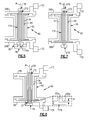
- the engine 20 also includes an airfoil assembly 60, which is shown in isolated view in Figure 2 .
- the airfoil assembly 60 is located in the turbine section 28 of the engine 20.
- the examples herein are not limited to the turbine section 28 and may be applied to other sections of the engine 20.
- the airfoil assembly 60 includes at least one airfoil 62 that has a hollow interior 64.
- the airfoil 62 can have a leading end, a trailing end, and pressure and a suction sides joining the leading and trailing ends.
- the airfoil assembly 60 could alternatively include additional airfoils 62.
- the airfoil assembly 60 can be an arc segment of a full annular vane assembly, for example, where each arc segment includes multiple airfoil vanes.
- the airfoil 62 includes a radially outer wall 62a and a radially inner wall 62b, relative to the engine central axis A.
- the radially inner and outer walls 62a/62b bound the core gas path C.
- the airfoil 62 is mechanically trapped/clamped between first and second platforms 66/68.
- At least one tie-spar 70 extends along an axis A1 through the first platform 66, the hollow interior 64 of the airfoil 62, and the second platform 68.
- At least one spacer portion 72 is arranged on the tie-spar 70.
- the airfoil assembly includes two such spacer portions 72, with one at either end of the tie-spar 70.
- the tie-spar 70 is secured to clamp the spacer portions 72, the first and second platforms 66/68, and the airfoil 62 together in a radial stack.
- the airfoil assembly can be affixed with a case structure CS, which mechanically supports the airfoil assembly 60 in the engine 20.
- the airfoil assembly 60 can be affixed to the case structure CS using mechanical hooks, fasteners, or the like.
- High-temperature materials are desired for the airfoil 62.
- such materials often have low ductility and low coefficient of thermal expansion ("CTE").
- CTE coefficient of thermal expansion
- the low ductility can make a component more susceptible to tensile stresses relative to higher ductility superalloys, and low CTE can contribute to thermally-induced stresses and lack of sufficient mechanical constraint with surrounding components that have different CTE.
- the airfoil assembly 60 provides an arrangement that permits use of low ductility, low CTE materials in the airfoil 62 while mitigating intolerable thermal and mechanical stresses and correctly positioning the component during operation, for example.
- the airfoil 62 is formed of a relatively low ductility, low CTE material in comparison to nickel-based alloy that is more conventionally used in turbine sections.
- Example low ductility, low CTE material can include, but is not limited to, monolithic ceramic material, ceramic matrix composites, and molybdenum-based alloys.
- the first and second platforms 66/68 and spacer portion 72 are formed of higher ductility, higher CTE materials, such as nickel-based alloys.
- the first and second platforms 66/68 can bear aerodynamic loads borne from the airfoil 62 to reduce stress on the airfoil, while the airfoil 62 bears the high temperatures and thermally protects the first and second platforms 66/68.
- the components of the airfoil assembly 60 thermally expand according to their individual CTE. Because the airfoil 62 is formed of a low CTE material, the airfoil 62 thermally expands along the axis A1 in an amount less than the thermal expansion of the tie-spar 70 and the platforms 66/68. That is, there is a thermal expansion difference D between a thermal expansion T1 of the tie-spar 70 in the axial direction A1 and a combined thermal expansion T2 of the airfoil 62 and the first and second platforms 66/68 in the same axial direction A1.
- each of the spacer portions 72 has an aspect ratio of length-to-width(diameter) of greater than one, with the length being along the axis A1 and the width being perpendicular to the axis A1.
- the elongation of the spacer portions 72 serves to increase thermal expansion of the spacer portions 72, while shorter spacer portions 72 would expand less for a given temperature increase.
- the spacer portions 72 function as thermal springs in the airfoil assembly 60 to maintain the tie-spar 70 in tension over wide operating temperature conditions in the engine 20.
- Figure 3 shows another example of the airfoil assembly 60.
- like reference numerals designate like elements where appropriate and reference numerals with the addition of one-hundred or multiples thereof designate modified elements that are understood to incorporate the same features and benefits of the corresponding elements.
- the first and second platforms 166/168 are relatively flat and the spacer portion 172 is shorter than the spacer portion 72 as shown in Figure 2 .
- the spacer portion 172 does not extend in the hollow interior 64 of the airfoil 62 and is thus outboard of the platform 166 with respect to the hollow interior 64.
- the tie-spar 170 includes a threaded end 170a that is secured with a threaded end cap 78.
- a classified spacer 80 is mechanically trapped between the threaded end cap 78 and the platform 268.
- the classified spacer is a cylindrical piece that is received onto the tie-spar 372.
- the classified spacer 80 can alternatively be located elsewhere along the stack of the airfoil assembly 60.
- a classified spacer is one which is selected from a group of different, preset size classes in accordance with a determined spacing in the stack. For example, manufacturing tolerances in the components of the airfoil assembly 60 can lead to a variation in spacing in the stack.
- the classified spacer 80 can be selected from the size classes in accordance with spacing determined from such tolerances.
- FIG 8 shows another example of the airfoil assembly 60 that is somewhat similar to that of Figure 4 except that in this example the spacer portions 472 are integrated into the platforms 366 and 466.
- each of the platforms 366/466 is a single, distinct piece that is monolithic and has a relatively enlarged portion that serves as the spacer portions 472.
- the relatively enlarged potions provide the thermal expansion T3 in the axial direction A1 that is greater than the thermal expansion difference D, discussed above.
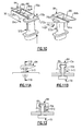
- FIG 9 shows another example airfoil assembly 60, but rather than a threaded end cap or the like, the tie-spar 70 is secured at one end with a clip 84.
- the spacer portion 572 includes a flange 572a to facilitate mounting of the clip 84.
- the clip 84 is a wedge clip that can be slidably received along the flange 572a such that spaced apart arms 84a/84b of the clip 84 are received about an enlarged end 70a of the tie-spar 70.
- the flange 572a Upon sliding the clip 84 over the enlarged end 70a and across the flange 572a, the flange 572a is received into the under-recess 90, thus locking the clip 84 on the spacer portion 572.
- the locking of the enlarged end 70a in the recess 88 and the locking of the flange 572a in the under-recess 90 serves to secure the tie-spar 70 and the spacer portion 572 together.
- FIGs 11A and 11B show additional views of the clip 84 secured on the tie-spar 70 and spacer portion 572.
- the enlarged end 70a of the tie-spar 70 includes sloped bearing surfaces 70b that engage the sloped surfaces 86 of the arms 84a/84b.
- the bearing surfaces 70b and the surfaces 86 are flat rather than sloped.
- Figure 13 shows a portion of the airfoil 62 and platform 66.
- the platform 66 is free of direct contact with the airfoil 62, and a spacer 89 is arranged there between to prevent contact.
- the material of the platform 66 is a superalloy and the material of the airfoil 62 is a refractory metal-based alloy or ceramic-based material, such materials can react if in direct contact.
- molybdenum such as from as a molybdenum-based alloy of the airfoil 62, can react with nickel-based alloys. Such reactions may debit the properties of an airfoil assembly.
- the spacer 89 is provided there between and chemically isolates the platform 66 from the airfoil 62.
- the spacer 89 is cobalt.
- additional such spacers 89 can be used in any of the airfoil assemblies 60 disclosed herein.
- such spacers 89 can also be used between any second platform 68 and the airfoil 62.
- the spacer 88 can be excluded such that the platform 66 and the airfoil 62 are in direct, intimate contact.
- the spacer 89 can be bonded to the platform 66, the airfoil 62, or both, rather than being mechanically trapped.
- Figure 14 shows selected portions of another example airfoil assembly 60.
- a portion of the hollow interior 64 of the airfoil 62 is shown in axial view with respect to axis A1, with the spacer 672 and tie-spar 370 extending there through.
- the spacer portion 672 and tie-spar 370 are sized such that there is a clearance gap CG there between.
- the clearance gap is annular.
- the exterior of the tie-spar 370 and the interior of the spacer portion 672, i.e., the surfaces that border the clearance gap include a thermal barrier coating 92.
- the thermal barrier coating 92 can be a ceramic-based material, such as but not limited to, a stabilized zirconia material.
- Figures 15A, 15B, 15C, 15D, 15E, and 15F show further examples, respectively, of airfoil assemblies 60 and tie-spars 70.
- the airfoil 62 is represented by a plurality of cavities, namely cavity X, Y, and Z. Cavity Z is at the leading edge of the airfoil and cavity X is at the trailing edge, while cavity Y is an intermediate cavity.
- the tie-spars 70 can have any of various cross-sectional geometries.
- the tie-spar 70 has a circular cross-section.
- the tie-spar 70 has a rectangular cross-section.
- FIGs 16A, 16B, and 16C show further examples of the baffle 76.
- the baffle 76 extends in the hollow interior 64 of the airfoil 62 but protrudes out from the hollow interior 64 such that lateral arms 76a and 76b are mechanically captured between the airfoil 62 and the platform 66.
- the lateral arms 76a and 76b include hooks 76c that interlock with corresponding recesses 76d in the platform 66 to mechanically secure the baffle 76.
- the lateral arms 76a and 76b include hooks 76b that interlock with protrusions 76e on the outer surface of the airfoils 62.
- FIG 17 shows another example with two airfoil assemblies 60.
- the airfoil assemblies 60 are circumferentially side-by-side in the depiction.
- the radially outer wall 62a of the airfoil 62 includes protruding radial arms 62c and the radially inner wall 62b of the airfoil includes protruding radial arms 62d.
- only radial arms 62c or only radial arms 62d could be used.
- the radial arms 62c/62d partially wrap or extend, respectively, around the platforms 66/68.
- the partial wrapping shields the platforms 66/68 from the core gas path C, thus reducing thermal distortion and exposure to high temperature excursions. Additionally, the circumferential sides of the arms 62c/62d serve as mate faces between neighboring airfoil assemblies in the engine 20.
Landscapes
- Engineering & Computer Science (AREA)
- Mechanical Engineering (AREA)
- General Engineering & Computer Science (AREA)
- Chemical & Material Sciences (AREA)
- Ceramic Engineering (AREA)
- Materials Engineering (AREA)
- Structures Of Non-Positive Displacement Pumps (AREA)
- Turbine Rotor Nozzle Sealing (AREA)
Applications Claiming Priority (1)
| Application Number | Priority Date | Filing Date | Title |
|---|---|---|---|
| US201462057748P | 2014-09-30 | 2014-09-30 |
Publications (2)
| Publication Number | Publication Date |
|---|---|
| EP3009601A1 true EP3009601A1 (fr) | 2016-04-20 |
| EP3009601B1 EP3009601B1 (fr) | 2019-08-14 |
Family
ID=54251372
Family Applications (1)
| Application Number | Title | Priority Date | Filing Date |
|---|---|---|---|
| EP15187602.6A Active EP3009601B1 (fr) | 2014-09-30 | 2015-09-30 | Ensemble d'aube avec entretoise et tirant |
Country Status (2)
| Country | Link |
|---|---|
| US (2) | US10107117B2 (fr) |
| EP (1) | EP3009601B1 (fr) |
Cited By (6)
| Publication number | Priority date | Publication date | Assignee | Title |
|---|---|---|---|---|
| US20160341054A1 (en) * | 2014-02-03 | 2016-11-24 | United Technologies Corporation | Gas turbine engine cooling fluid composite tube |
| EP3269938A1 (fr) * | 2016-07-13 | 2018-01-17 | General Electric Company | Système et procédé d'assemblage de carénage d'aube à contrainte réduite |
| FR3061928A1 (fr) * | 2017-01-18 | 2018-07-20 | Safran Aircraft Engines | Turbine de turbomachine comprenant un etage distributeur en materiau composite a matrice ceramique |
| FR3080146A1 (fr) * | 2018-04-17 | 2019-10-18 | Safran Aircraft Engines | Distributeur en cmc avec reprise d'effort |
| US10947864B2 (en) * | 2016-09-12 | 2021-03-16 | Siemens Energy Global GmbH & Co. KG | Gas turbine with separate cooling for turbine and exhaust casing |
| EP3819464A1 (fr) * | 2019-11-08 | 2021-05-12 | Raytheon Technologies Corporation | Aube avec joint et plaque de retenue |
Families Citing this family (43)
| Publication number | Priority date | Publication date | Assignee | Title |
|---|---|---|---|---|
| US20160169033A1 (en) * | 2014-12-15 | 2016-06-16 | General Electric Company | Apparatus and system for ceramic matrix composite attachment |
| US10982564B2 (en) | 2014-12-15 | 2021-04-20 | General Electric Company | Apparatus and system for ceramic matrix composite attachment |
| US10012092B2 (en) * | 2015-08-12 | 2018-07-03 | United Technologies Corporation | Low turn loss baffle flow diverter |
| US10746038B2 (en) | 2016-11-17 | 2020-08-18 | Raytheon Technologies Corporation | Airfoil with airfoil piece having radial seal |
| US10711794B2 (en) | 2016-11-17 | 2020-07-14 | Raytheon Technologies Corporation | Airfoil with geometrically segmented coating section having mechanical secondary bonding feature |
| US10711624B2 (en) | 2016-11-17 | 2020-07-14 | Raytheon Technologies Corporation | Airfoil with geometrically segmented coating section |
| US10480334B2 (en) | 2016-11-17 | 2019-11-19 | United Technologies Corporation | Airfoil with geometrically segmented coating section |
| US10309238B2 (en) | 2016-11-17 | 2019-06-04 | United Technologies Corporation | Turbine engine component with geometrically segmented coating section and cooling passage |
| US10436062B2 (en) | 2016-11-17 | 2019-10-08 | United Technologies Corporation | Article having ceramic wall with flow turbulators |
| US10436049B2 (en) | 2016-11-17 | 2019-10-08 | United Technologies Corporation | Airfoil with dual profile leading end |
| US10808554B2 (en) | 2016-11-17 | 2020-10-20 | Raytheon Technologies Corporation | Method for making ceramic turbine engine article |
| US10731495B2 (en) | 2016-11-17 | 2020-08-04 | Raytheon Technologies Corporation | Airfoil with panel having perimeter seal |
| US10598029B2 (en) | 2016-11-17 | 2020-03-24 | United Technologies Corporation | Airfoil with panel and side edge cooling |
| US10408082B2 (en) | 2016-11-17 | 2019-09-10 | United Technologies Corporation | Airfoil with retention pocket holding airfoil piece |
| US10408090B2 (en) | 2016-11-17 | 2019-09-10 | United Technologies Corporation | Gas turbine engine article with panel retained by preloaded compliant member |
| US10415407B2 (en) | 2016-11-17 | 2019-09-17 | United Technologies Corporation | Airfoil pieces secured with endwall section |
| US10428663B2 (en) | 2016-11-17 | 2019-10-01 | United Technologies Corporation | Airfoil with tie member and spring |
| US10605088B2 (en) | 2016-11-17 | 2020-03-31 | United Technologies Corporation | Airfoil endwall with partial integral airfoil wall |
| US10677091B2 (en) | 2016-11-17 | 2020-06-09 | Raytheon Technologies Corporation | Airfoil with sealed baffle |
| US10711616B2 (en) | 2016-11-17 | 2020-07-14 | Raytheon Technologies Corporation | Airfoil having endwall panels |
| US10502070B2 (en) | 2016-11-17 | 2019-12-10 | United Technologies Corporation | Airfoil with laterally insertable baffle |
| US10309226B2 (en) | 2016-11-17 | 2019-06-04 | United Technologies Corporation | Airfoil having panels |
| US10767487B2 (en) | 2016-11-17 | 2020-09-08 | Raytheon Technologies Corporation | Airfoil with panel having flow guide |
| US10662779B2 (en) | 2016-11-17 | 2020-05-26 | Raytheon Technologies Corporation | Gas turbine engine component with degradation cooling scheme |
| US10662782B2 (en) | 2016-11-17 | 2020-05-26 | Raytheon Technologies Corporation | Airfoil with airfoil piece having axial seal |
| US10570765B2 (en) | 2016-11-17 | 2020-02-25 | United Technologies Corporation | Endwall arc segments with cover across joint |
| US10598025B2 (en) | 2016-11-17 | 2020-03-24 | United Technologies Corporation | Airfoil with rods adjacent a core structure |
| US10677079B2 (en) | 2016-11-17 | 2020-06-09 | Raytheon Technologies Corporation | Airfoil with ceramic airfoil piece having internal cooling circuit |
| US10458262B2 (en) | 2016-11-17 | 2019-10-29 | United Technologies Corporation | Airfoil with seal between endwall and airfoil section |
| US10428658B2 (en) | 2016-11-17 | 2019-10-01 | United Technologies Corporation | Airfoil with panel fastened to core structure |
| US10480331B2 (en) | 2016-11-17 | 2019-11-19 | United Technologies Corporation | Airfoil having panel with geometrically segmented coating |
| US10830071B2 (en) * | 2017-01-23 | 2020-11-10 | General Electric Company | System and method for the hybrid construction of multi-piece parts |
| US10557362B2 (en) | 2017-03-30 | 2020-02-11 | General Electric Company | Method and system for a pressure activated cap seal |
| FR3080145B1 (fr) * | 2018-04-17 | 2020-05-01 | Safran Aircraft Engines | Distributeur en cmc avec reprise d'effort par une pince etanche |
| US10774662B2 (en) * | 2018-07-17 | 2020-09-15 | Rolls-Royce Corporation | Separable turbine vane stage |
| US11143105B2 (en) | 2018-12-19 | 2021-10-12 | Unison Industries, Llc | Mounting assembly and fan casing assembly |
| US11261747B2 (en) * | 2019-05-17 | 2022-03-01 | Rolls-Royce Plc | Ceramic matrix composite vane with added platform |
| US11255194B2 (en) | 2020-02-11 | 2022-02-22 | Raytheon Technologies Corporation | Vane arc segment platform flange with cap |
| US11359497B1 (en) | 2020-12-21 | 2022-06-14 | Raytheon Technologies Corporation | Vane with baffle and recessed spar |
| US11448096B2 (en) * | 2021-01-15 | 2022-09-20 | Raytheon Technologies Corporation | Vane arc segment support platform with curved radial channel |
| US11732596B2 (en) | 2021-12-22 | 2023-08-22 | Rolls-Royce Plc | Ceramic matrix composite turbine vane assembly having minimalistic support spars |
| CN117307258A (zh) * | 2022-06-21 | 2023-12-29 | 中国航发商用航空发动机有限责任公司 | 一种涡轮导叶结构 |
| CN119914368A (zh) * | 2023-10-30 | 2025-05-02 | 中国航发商用航空发动机有限责任公司 | 涡轮导叶装配结构 |
Citations (4)
| Publication number | Priority date | Publication date | Assignee | Title |
|---|---|---|---|---|
| GB2094895A (en) * | 1981-03-16 | 1982-09-22 | Mtu Muenchen Gmbh | Turbine blade |
| JPS6166802A (ja) * | 1984-09-10 | 1986-04-05 | Mitsubishi Heavy Ind Ltd | ガスタ−ビンのタ−ビン翼 |
| US5538380A (en) * | 1994-06-27 | 1996-07-23 | Solar Turbines Incorporated | Metallic nut for use with ceramic threads |
| EP2584152A2 (fr) * | 2011-10-17 | 2013-04-24 | United Technologies Corporation | Cadre de turbine intermédiaire (MTF) pour un moteur à turbine à gaz |
Family Cites Families (5)
| Publication number | Priority date | Publication date | Assignee | Title |
|---|---|---|---|---|
| US7329087B2 (en) | 2005-09-19 | 2008-02-12 | General Electric Company | Seal-less CMC vane to platform interfaces |
| US8313275B2 (en) | 2010-08-13 | 2012-11-20 | Ohio Valley Precision, Inc. | Wedge fastener |
| US9587514B2 (en) | 2012-07-13 | 2017-03-07 | United Technologies Corporation | Vane insertable tie rods with keyed connections |
| US9222413B2 (en) | 2012-07-13 | 2015-12-29 | United Technologies Corporation | Mid-turbine frame with threaded spokes |
| US20140255174A1 (en) | 2012-12-21 | 2014-09-11 | United Technologies Corporation | Manufacture of full ring strut vane pack |
-
2015
- 2015-08-28 US US14/838,412 patent/US10107117B2/en active Active
- 2015-09-30 EP EP15187602.6A patent/EP3009601B1/fr active Active
-
2018
- 2018-10-09 US US16/154,754 patent/US10465540B2/en active Active
Patent Citations (4)
| Publication number | Priority date | Publication date | Assignee | Title |
|---|---|---|---|---|
| GB2094895A (en) * | 1981-03-16 | 1982-09-22 | Mtu Muenchen Gmbh | Turbine blade |
| JPS6166802A (ja) * | 1984-09-10 | 1986-04-05 | Mitsubishi Heavy Ind Ltd | ガスタ−ビンのタ−ビン翼 |
| US5538380A (en) * | 1994-06-27 | 1996-07-23 | Solar Turbines Incorporated | Metallic nut for use with ceramic threads |
| EP2584152A2 (fr) * | 2011-10-17 | 2013-04-24 | United Technologies Corporation | Cadre de turbine intermédiaire (MTF) pour un moteur à turbine à gaz |
Cited By (12)
| Publication number | Priority date | Publication date | Assignee | Title |
|---|---|---|---|---|
| US20160341054A1 (en) * | 2014-02-03 | 2016-11-24 | United Technologies Corporation | Gas turbine engine cooling fluid composite tube |
| US10662792B2 (en) * | 2014-02-03 | 2020-05-26 | Raytheon Technologies Corporation | Gas turbine engine cooling fluid composite tube |
| EP3269938A1 (fr) * | 2016-07-13 | 2018-01-17 | General Electric Company | Système et procédé d'assemblage de carénage d'aube à contrainte réduite |
| US10947864B2 (en) * | 2016-09-12 | 2021-03-16 | Siemens Energy Global GmbH & Co. KG | Gas turbine with separate cooling for turbine and exhaust casing |
| FR3061928A1 (fr) * | 2017-01-18 | 2018-07-20 | Safran Aircraft Engines | Turbine de turbomachine comprenant un etage distributeur en materiau composite a matrice ceramique |
| FR3061929A1 (fr) * | 2017-01-18 | 2018-07-20 | Safran Aircraft Engines | Turbine de turbomachine comprenant un etage distributeur en materiau composite a matrice ceramique |
| US10738635B2 (en) | 2017-01-18 | 2020-08-11 | Safran Aircraft Engines | Turbine engine turbine including a nozzle stage made of ceramic matrix composite material |
| FR3080146A1 (fr) * | 2018-04-17 | 2019-10-18 | Safran Aircraft Engines | Distributeur en cmc avec reprise d'effort |
| WO2019202259A3 (fr) * | 2018-04-17 | 2020-01-09 | Safran Aircraft Engines | Distributeur en cmc avec reprise d'effort |
| US11391170B2 (en) | 2018-04-17 | 2022-07-19 | Safran Aircraft Engines | Load-bearing CMC nozzle diaphragm |
| EP3819464A1 (fr) * | 2019-11-08 | 2021-05-12 | Raytheon Technologies Corporation | Aube avec joint et plaque de retenue |
| US11174794B2 (en) | 2019-11-08 | 2021-11-16 | Raytheon Technologies Corporation | Vane with seal and retainer plate |
Also Published As
| Publication number | Publication date |
|---|---|
| US20190093490A1 (en) | 2019-03-28 |
| US20160090851A1 (en) | 2016-03-31 |
| US10107117B2 (en) | 2018-10-23 |
| US10465540B2 (en) | 2019-11-05 |
| EP3009601B1 (fr) | 2019-08-14 |
Similar Documents
| Publication | Publication Date | Title |
|---|---|---|
| US10465540B2 (en) | Airfoil assembly with spacer and tie-spar | |
| EP3000979B1 (fr) | Segment d'arc d'aube pincé ayant des caractéristiques de transmission de charge | |
| EP3650657B1 (fr) | Ensemble d'étanchéité avec plaque d'étanchéité d'impact | |
| EP2875224B1 (fr) | Commande de position radiale d'une structure supportée par une boîte | |
| EP3219935B1 (fr) | Joint d'air extérieur d'aube de moteur à turbine ayant un chariot transmetteur de charge | |
| EP3219933A1 (fr) | Joint d'aube externe étanche avec bouclier thermique segmenté | |
| EP3971391B1 (fr) | Aube de turbine à gaz en cmc avec longeron de support et déflecteur avec refroidissement par impact | |
| EP3219924B1 (fr) | Joint d'air extérieur d'aube de moteur à turbine avec plaque de couverture de transmission de charge | |
| EP4086436A1 (fr) | Assemblages d'une aube statorique d'une turbine á gaz | |
| EP3219934B1 (fr) | Ensemble d'étanchéité pour moteur de turbine à gaz | |
| EP3219930B1 (fr) | Joint d'étanchéité à l'air externe d'aube avec écran thermique | |
| EP3892822B1 (fr) | Système de support d'aube statorique | |
| EP3047108B1 (fr) | Ensemble de profil aérodynamique constitué par un matériau résistant aux températures élevées | |
| EP3805530B1 (fr) | Joint à l'air extérieur d'aubes pour moteur à turbine à gaz et procédé d'assemblage ou de démontage correspondant | |
| EP3751101A1 (fr) | Aube comportant des pièces d' aube en céramique et une étanchéité | |
| EP3708785B1 (fr) | Ensemble joint d'air extérieur d'aube avec support de joint avec fixations en queue d'aronde | |
| US12215606B2 (en) | Turbine engine with TOBI supporting vanes | |
| EP3808938B1 (fr) | Composant à profil aérodynamique avec une marge au bord de fuite comportant une échancrure | |
| EP3012412B1 (fr) | Moteur à turbine à gaz et procédé associé pour la maintenance d'une aube en plusieurs pièces déviant un flux |
Legal Events
| Date | Code | Title | Description |
|---|---|---|---|
| PUAI | Public reference made under article 153(3) epc to a published international application that has entered the european phase |
Free format text: ORIGINAL CODE: 0009012 |
|
| AK | Designated contracting states |
Kind code of ref document: A1 Designated state(s): AL AT BE BG CH CY CZ DE DK EE ES FI FR GB GR HR HU IE IS IT LI LT LU LV MC MK MT NL NO PL PT RO RS SE SI SK SM TR |
|
| AX | Request for extension of the european patent |
Extension state: BA ME |
|
| RAP1 | Party data changed (applicant data changed or rights of an application transferred) |
Owner name: UNITED TECHNOLOGIES CORPORATION |
|
| 17P | Request for examination filed |
Effective date: 20161020 |
|
| RBV | Designated contracting states (corrected) |
Designated state(s): AL AT BE BG CH CY CZ DE DK EE ES FI FR GB GR HR HU IE IS IT LI LT LU LV MC MK MT NL NO PL PT RO RS SE SI SK SM TR |
|
| GRAP | Despatch of communication of intention to grant a patent |
Free format text: ORIGINAL CODE: EPIDOSNIGR1 |
|
| STAA | Information on the status of an ep patent application or granted ep patent |
Free format text: STATUS: GRANT OF PATENT IS INTENDED |
|
| RIC1 | Information provided on ipc code assigned before grant |
Ipc: F01D 5/28 20060101AFI20180730BHEP Ipc: F01D 9/04 20060101ALI20180730BHEP Ipc: F01D 25/24 20060101ALI20180730BHEP |
|
| INTG | Intention to grant announced |
Effective date: 20180823 |
|
| RIN1 | Information on inventor provided before grant (corrected) |
Inventor name: DUBE, BRYAN P. Inventor name: CARR, JESSE M. |
|
| GRAJ | Information related to disapproval of communication of intention to grant by the applicant or resumption of examination proceedings by the epo deleted |
Free format text: ORIGINAL CODE: EPIDOSDIGR1 |
|
| STAA | Information on the status of an ep patent application or granted ep patent |
Free format text: STATUS: REQUEST FOR EXAMINATION WAS MADE |
|
| INTC | Intention to grant announced (deleted) | ||
| GRAP | Despatch of communication of intention to grant a patent |
Free format text: ORIGINAL CODE: EPIDOSNIGR1 |
|
| STAA | Information on the status of an ep patent application or granted ep patent |
Free format text: STATUS: GRANT OF PATENT IS INTENDED |
|
| INTG | Intention to grant announced |
Effective date: 20190221 |
|
| GRAS | Grant fee paid |
Free format text: ORIGINAL CODE: EPIDOSNIGR3 |
|
| GRAA | (expected) grant |
Free format text: ORIGINAL CODE: 0009210 |
|
| STAA | Information on the status of an ep patent application or granted ep patent |
Free format text: STATUS: THE PATENT HAS BEEN GRANTED |
|
| AK | Designated contracting states |
Kind code of ref document: B1 Designated state(s): AL AT BE BG CH CY CZ DE DK EE ES FI FR GB GR HR HU IE IS IT LI LT LU LV MC MK MT NL NO PL PT RO RS SE SI SK SM TR |
|
| REG | Reference to a national code |
Ref country code: GB Ref legal event code: FG4D |
|
| REG | Reference to a national code |
Ref country code: CH Ref legal event code: EP Ref country code: AT Ref legal event code: REF Ref document number: 1167269 Country of ref document: AT Kind code of ref document: T Effective date: 20190815 |
|
| REG | Reference to a national code |
Ref country code: IE Ref legal event code: FG4D |
|
| REG | Reference to a national code |
Ref country code: DE Ref legal event code: R096 Ref document number: 602015035714 Country of ref document: DE |
|
| REG | Reference to a national code |
Ref country code: NL Ref legal event code: MP Effective date: 20190814 |
|
| REG | Reference to a national code |
Ref country code: LT Ref legal event code: MG4D |
|
| PG25 | Lapsed in a contracting state [announced via postgrant information from national office to epo] |
Ref country code: LT Free format text: LAPSE BECAUSE OF FAILURE TO SUBMIT A TRANSLATION OF THE DESCRIPTION OR TO PAY THE FEE WITHIN THE PRESCRIBED TIME-LIMIT Effective date: 20190814 Ref country code: NL Free format text: LAPSE BECAUSE OF FAILURE TO SUBMIT A TRANSLATION OF THE DESCRIPTION OR TO PAY THE FEE WITHIN THE PRESCRIBED TIME-LIMIT Effective date: 20190814 Ref country code: BG Free format text: LAPSE BECAUSE OF FAILURE TO SUBMIT A TRANSLATION OF THE DESCRIPTION OR TO PAY THE FEE WITHIN THE PRESCRIBED TIME-LIMIT Effective date: 20191114 Ref country code: SE Free format text: LAPSE BECAUSE OF FAILURE TO SUBMIT A TRANSLATION OF THE DESCRIPTION OR TO PAY THE FEE WITHIN THE PRESCRIBED TIME-LIMIT Effective date: 20190814 Ref country code: NO Free format text: LAPSE BECAUSE OF FAILURE TO SUBMIT A TRANSLATION OF THE DESCRIPTION OR TO PAY THE FEE WITHIN THE PRESCRIBED TIME-LIMIT Effective date: 20191114 Ref country code: PT Free format text: LAPSE BECAUSE OF FAILURE TO SUBMIT A TRANSLATION OF THE DESCRIPTION OR TO PAY THE FEE WITHIN THE PRESCRIBED TIME-LIMIT Effective date: 20191216 Ref country code: HR Free format text: LAPSE BECAUSE OF FAILURE TO SUBMIT A TRANSLATION OF THE DESCRIPTION OR TO PAY THE FEE WITHIN THE PRESCRIBED TIME-LIMIT Effective date: 20190814 Ref country code: FI Free format text: LAPSE BECAUSE OF FAILURE TO SUBMIT A TRANSLATION OF THE DESCRIPTION OR TO PAY THE FEE WITHIN THE PRESCRIBED TIME-LIMIT Effective date: 20190814 |
|
| REG | Reference to a national code |
Ref country code: AT Ref legal event code: MK05 Ref document number: 1167269 Country of ref document: AT Kind code of ref document: T Effective date: 20190814 |
|
| PG25 | Lapsed in a contracting state [announced via postgrant information from national office to epo] |
Ref country code: IS Free format text: LAPSE BECAUSE OF FAILURE TO SUBMIT A TRANSLATION OF THE DESCRIPTION OR TO PAY THE FEE WITHIN THE PRESCRIBED TIME-LIMIT Effective date: 20191214 Ref country code: LV Free format text: LAPSE BECAUSE OF FAILURE TO SUBMIT A TRANSLATION OF THE DESCRIPTION OR TO PAY THE FEE WITHIN THE PRESCRIBED TIME-LIMIT Effective date: 20190814 Ref country code: RS Free format text: LAPSE BECAUSE OF FAILURE TO SUBMIT A TRANSLATION OF THE DESCRIPTION OR TO PAY THE FEE WITHIN THE PRESCRIBED TIME-LIMIT Effective date: 20190814 Ref country code: GR Free format text: LAPSE BECAUSE OF FAILURE TO SUBMIT A TRANSLATION OF THE DESCRIPTION OR TO PAY THE FEE WITHIN THE PRESCRIBED TIME-LIMIT Effective date: 20191115 Ref country code: ES Free format text: LAPSE BECAUSE OF FAILURE TO SUBMIT A TRANSLATION OF THE DESCRIPTION OR TO PAY THE FEE WITHIN THE PRESCRIBED TIME-LIMIT Effective date: 20190814 Ref country code: AL Free format text: LAPSE BECAUSE OF FAILURE TO SUBMIT A TRANSLATION OF THE DESCRIPTION OR TO PAY THE FEE WITHIN THE PRESCRIBED TIME-LIMIT Effective date: 20190814 |
|
| PG25 | Lapsed in a contracting state [announced via postgrant information from national office to epo] |
Ref country code: TR Free format text: LAPSE BECAUSE OF FAILURE TO SUBMIT A TRANSLATION OF THE DESCRIPTION OR TO PAY THE FEE WITHIN THE PRESCRIBED TIME-LIMIT Effective date: 20190814 |
|
| PG25 | Lapsed in a contracting state [announced via postgrant information from national office to epo] |
Ref country code: RO Free format text: LAPSE BECAUSE OF FAILURE TO SUBMIT A TRANSLATION OF THE DESCRIPTION OR TO PAY THE FEE WITHIN THE PRESCRIBED TIME-LIMIT Effective date: 20190814 Ref country code: DK Free format text: LAPSE BECAUSE OF FAILURE TO SUBMIT A TRANSLATION OF THE DESCRIPTION OR TO PAY THE FEE WITHIN THE PRESCRIBED TIME-LIMIT Effective date: 20190814 Ref country code: AT Free format text: LAPSE BECAUSE OF FAILURE TO SUBMIT A TRANSLATION OF THE DESCRIPTION OR TO PAY THE FEE WITHIN THE PRESCRIBED TIME-LIMIT Effective date: 20190814 Ref country code: EE Free format text: LAPSE BECAUSE OF FAILURE TO SUBMIT A TRANSLATION OF THE DESCRIPTION OR TO PAY THE FEE WITHIN THE PRESCRIBED TIME-LIMIT Effective date: 20190814 Ref country code: IT Free format text: LAPSE BECAUSE OF FAILURE TO SUBMIT A TRANSLATION OF THE DESCRIPTION OR TO PAY THE FEE WITHIN THE PRESCRIBED TIME-LIMIT Effective date: 20190814 Ref country code: PL Free format text: LAPSE BECAUSE OF FAILURE TO SUBMIT A TRANSLATION OF THE DESCRIPTION OR TO PAY THE FEE WITHIN THE PRESCRIBED TIME-LIMIT Effective date: 20190814 |
|
| PG25 | Lapsed in a contracting state [announced via postgrant information from national office to epo] |
Ref country code: SK Free format text: LAPSE BECAUSE OF FAILURE TO SUBMIT A TRANSLATION OF THE DESCRIPTION OR TO PAY THE FEE WITHIN THE PRESCRIBED TIME-LIMIT Effective date: 20190814 Ref country code: CZ Free format text: LAPSE BECAUSE OF FAILURE TO SUBMIT A TRANSLATION OF THE DESCRIPTION OR TO PAY THE FEE WITHIN THE PRESCRIBED TIME-LIMIT Effective date: 20190814 Ref country code: MC Free format text: LAPSE BECAUSE OF FAILURE TO SUBMIT A TRANSLATION OF THE DESCRIPTION OR TO PAY THE FEE WITHIN THE PRESCRIBED TIME-LIMIT Effective date: 20190814 Ref country code: IS Free format text: LAPSE BECAUSE OF FAILURE TO SUBMIT A TRANSLATION OF THE DESCRIPTION OR TO PAY THE FEE WITHIN THE PRESCRIBED TIME-LIMIT Effective date: 20200224 Ref country code: SM Free format text: LAPSE BECAUSE OF FAILURE TO SUBMIT A TRANSLATION OF THE DESCRIPTION OR TO PAY THE FEE WITHIN THE PRESCRIBED TIME-LIMIT Effective date: 20190814 |
|
| REG | Reference to a national code |
Ref country code: CH Ref legal event code: PL |
|
| REG | Reference to a national code |
Ref country code: DE Ref legal event code: R097 Ref document number: 602015035714 Country of ref document: DE |
|
| PLBE | No opposition filed within time limit |
Free format text: ORIGINAL CODE: 0009261 |
|
| STAA | Information on the status of an ep patent application or granted ep patent |
Free format text: STATUS: NO OPPOSITION FILED WITHIN TIME LIMIT |
|
| PG2D | Information on lapse in contracting state deleted |
Ref country code: IS |
|
| PG25 | Lapsed in a contracting state [announced via postgrant information from national office to epo] |
Ref country code: LI Free format text: LAPSE BECAUSE OF NON-PAYMENT OF DUE FEES Effective date: 20190930 Ref country code: CH Free format text: LAPSE BECAUSE OF NON-PAYMENT OF DUE FEES Effective date: 20190930 Ref country code: LU Free format text: LAPSE BECAUSE OF NON-PAYMENT OF DUE FEES Effective date: 20190930 Ref country code: IE Free format text: LAPSE BECAUSE OF NON-PAYMENT OF DUE FEES Effective date: 20190930 |
|
| 26N | No opposition filed |
Effective date: 20200603 |
|
| REG | Reference to a national code |
Ref country code: BE Ref legal event code: MM Effective date: 20190930 |
|
| PG25 | Lapsed in a contracting state [announced via postgrant information from national office to epo] |
Ref country code: BE Free format text: LAPSE BECAUSE OF NON-PAYMENT OF DUE FEES Effective date: 20190930 Ref country code: SI Free format text: LAPSE BECAUSE OF FAILURE TO SUBMIT A TRANSLATION OF THE DESCRIPTION OR TO PAY THE FEE WITHIN THE PRESCRIBED TIME-LIMIT Effective date: 20190814 |
|
| PG25 | Lapsed in a contracting state [announced via postgrant information from national office to epo] |
Ref country code: CY Free format text: LAPSE BECAUSE OF FAILURE TO SUBMIT A TRANSLATION OF THE DESCRIPTION OR TO PAY THE FEE WITHIN THE PRESCRIBED TIME-LIMIT Effective date: 20190814 |
|
| PG25 | Lapsed in a contracting state [announced via postgrant information from national office to epo] |
Ref country code: MT Free format text: LAPSE BECAUSE OF FAILURE TO SUBMIT A TRANSLATION OF THE DESCRIPTION OR TO PAY THE FEE WITHIN THE PRESCRIBED TIME-LIMIT Effective date: 20190814 Ref country code: HU Free format text: LAPSE BECAUSE OF FAILURE TO SUBMIT A TRANSLATION OF THE DESCRIPTION OR TO PAY THE FEE WITHIN THE PRESCRIBED TIME-LIMIT; INVALID AB INITIO Effective date: 20150930 |
|
| PG25 | Lapsed in a contracting state [announced via postgrant information from national office to epo] |
Ref country code: MK Free format text: LAPSE BECAUSE OF FAILURE TO SUBMIT A TRANSLATION OF THE DESCRIPTION OR TO PAY THE FEE WITHIN THE PRESCRIBED TIME-LIMIT Effective date: 20190814 |
|
| REG | Reference to a national code |
Ref country code: DE Ref legal event code: R081 Ref document number: 602015035714 Country of ref document: DE Owner name: RAYTHEON TECHNOLOGIES CORPORATION (N.D.GES.D.S, US Free format text: FORMER OWNER: UNITED TECHNOLOGIES CORPORATION, FARMINGTON, CONN., US Ref country code: DE Ref legal event code: R081 Ref document number: 602015035714 Country of ref document: DE Owner name: RTX CORPORATION (N.D.GES.D. STAATES DELAWARE),, US Free format text: FORMER OWNER: UNITED TECHNOLOGIES CORPORATION, FARMINGTON, CONN., US |
|
| P01 | Opt-out of the competence of the unified patent court (upc) registered |
Effective date: 20230520 |
|
| PGFP | Annual fee paid to national office [announced via postgrant information from national office to epo] |
Ref country code: DE Payment date: 20250820 Year of fee payment: 11 |
|
| PGFP | Annual fee paid to national office [announced via postgrant information from national office to epo] |
Ref country code: GB Payment date: 20250822 Year of fee payment: 11 |
|
| PGFP | Annual fee paid to national office [announced via postgrant information from national office to epo] |
Ref country code: FR Payment date: 20250820 Year of fee payment: 11 |
|
| REG | Reference to a national code |
Ref country code: DE Ref legal event code: R081 Ref document number: 602015035714 Country of ref document: DE Owner name: RTX CORPORATION (N.D.GES.D. STAATES DELAWARE),, US Free format text: FORMER OWNER: RAYTHEON TECHNOLOGIES CORPORATION (N.D.GES.D.STAATES DELAWARE), ARLINGTON, VA, US |