EP2584232A2 - Dispositif de stockage de produits en vrac ou fluides - Google Patents
Dispositif de stockage de produits en vrac ou fluides Download PDFInfo
- Publication number
- EP2584232A2 EP2584232A2 EP12006989.3A EP12006989A EP2584232A2 EP 2584232 A2 EP2584232 A2 EP 2584232A2 EP 12006989 A EP12006989 A EP 12006989A EP 2584232 A2 EP2584232 A2 EP 2584232A2
- Authority
- EP
- European Patent Office
- Prior art keywords
- siphon
- reservoir
- container
- inert gas
- level
- Prior art date
- Legal status (The legal status is an assumption and is not a legal conclusion. Google has not performed a legal analysis and makes no representation as to the accuracy of the status listed.)
- Withdrawn
Links
- 239000012530 fluid Substances 0.000 title 1
- 239000011261 inert gas Substances 0.000 claims abstract description 44
- 239000007788 liquid Substances 0.000 claims abstract description 39
- 239000007789 gas Substances 0.000 claims abstract description 34
- XKRFYHLGVUSROY-UHFFFAOYSA-N Argon Chemical compound [Ar] XKRFYHLGVUSROY-UHFFFAOYSA-N 0.000 claims abstract description 6
- IJGRMHOSHXDMSA-UHFFFAOYSA-N Atomic nitrogen Chemical compound N#N IJGRMHOSHXDMSA-UHFFFAOYSA-N 0.000 claims abstract description 6
- 229910052786 argon Inorganic materials 0.000 claims abstract description 3
- 238000007599 discharging Methods 0.000 claims abstract description 3
- 239000001307 helium Substances 0.000 claims abstract description 3
- 229910052734 helium Inorganic materials 0.000 claims abstract description 3
- SWQJXJOGLNCZEY-UHFFFAOYSA-N helium atom Chemical compound [He] SWQJXJOGLNCZEY-UHFFFAOYSA-N 0.000 claims abstract description 3
- 239000000203 mixture Substances 0.000 claims abstract description 3
- 229910052757 nitrogen Inorganic materials 0.000 claims abstract description 3
- 239000003814 drug Substances 0.000 claims description 10
- 229940079593 drug Drugs 0.000 claims description 8
- 230000009969 flowable effect Effects 0.000 claims description 7
- XLYOFNOQVPJJNP-UHFFFAOYSA-N water Substances O XLYOFNOQVPJJNP-UHFFFAOYSA-N 0.000 claims description 6
- 235000013305 food Nutrition 0.000 claims description 4
- OKTJSMMVPCPJKN-UHFFFAOYSA-N Carbon Chemical compound [C] OKTJSMMVPCPJKN-UHFFFAOYSA-N 0.000 claims description 3
- 229910052799 carbon Inorganic materials 0.000 claims description 3
- 238000000855 fermentation Methods 0.000 description 5
- 230000004151 fermentation Effects 0.000 description 5
- 230000004888 barrier function Effects 0.000 description 3
- 241000894006 Bacteria Species 0.000 description 2
- 244000052616 bacterial pathogen Species 0.000 description 2
- 238000010586 diagram Methods 0.000 description 2
- 238000007654 immersion Methods 0.000 description 2
- 238000007789 sealing Methods 0.000 description 2
- 239000013543 active substance Substances 0.000 description 1
- QVGXLLKOCUKJST-UHFFFAOYSA-N atomic oxygen Chemical compound [O] QVGXLLKOCUKJST-UHFFFAOYSA-N 0.000 description 1
- 230000000903 blocking effect Effects 0.000 description 1
- 238000010276 construction Methods 0.000 description 1
- 230000001590 oxidative effect Effects 0.000 description 1
- 239000001301 oxygen Substances 0.000 description 1
- 229910052760 oxygen Inorganic materials 0.000 description 1
- 230000035515 penetration Effects 0.000 description 1
- 230000001105 regulatory effect Effects 0.000 description 1
- 229910001220 stainless steel Inorganic materials 0.000 description 1
- 239000010935 stainless steel Substances 0.000 description 1
- 239000000126 substance Substances 0.000 description 1
Images


Classifications
-
- F—MECHANICAL ENGINEERING; LIGHTING; HEATING; WEAPONS; BLASTING
- F16—ENGINEERING ELEMENTS AND UNITS; GENERAL MEASURES FOR PRODUCING AND MAINTAINING EFFECTIVE FUNCTIONING OF MACHINES OR INSTALLATIONS; THERMAL INSULATION IN GENERAL
- F16K—VALVES; TAPS; COCKS; ACTUATING-FLOATS; DEVICES FOR VENTING OR AERATING
- F16K13/00—Other constructional types of cut-off apparatus; Arrangements for cutting-off
- F16K13/08—Arrangements for cutting-off not used
- F16K13/10—Arrangements for cutting-off not used by means of liquid or granular medium
-
- B—PERFORMING OPERATIONS; TRANSPORTING
- B65—CONVEYING; PACKING; STORING; HANDLING THIN OR FILAMENTARY MATERIAL
- B65D—CONTAINERS FOR STORAGE OR TRANSPORT OF ARTICLES OR MATERIALS, e.g. BAGS, BARRELS, BOTTLES, BOXES, CANS, CARTONS, CRATES, DRUMS, JARS, TANKS, HOPPERS, FORWARDING CONTAINERS; ACCESSORIES, CLOSURES, OR FITTINGS THEREFOR; PACKAGING ELEMENTS; PACKAGES
- B65D88/00—Large containers
- B65D88/74—Large containers having means for heating, cooling, aerating or other conditioning of contents
-
- F—MECHANICAL ENGINEERING; LIGHTING; HEATING; WEAPONS; BLASTING
- F16—ENGINEERING ELEMENTS AND UNITS; GENERAL MEASURES FOR PRODUCING AND MAINTAINING EFFECTIVE FUNCTIONING OF MACHINES OR INSTALLATIONS; THERMAL INSULATION IN GENERAL
- F16K—VALVES; TAPS; COCKS; ACTUATING-FLOATS; DEVICES FOR VENTING OR AERATING
- F16K17/00—Safety valves; Equalising valves, e.g. pressure relief valves
- F16K17/18—Safety valves; Equalising valves, e.g. pressure relief valves opening on surplus pressure on either side
- F16K17/19—Equalising valves predominantly for tanks
- F16K17/192—Equalising valves predominantly for tanks with closure member in the form of a movable liquid column
Definitions
- the invention relates to a device for storing pourable or flowable products.
- the device is intended in particular for storing foods, medicaments or active substances for medicaments in liquid form, which are to be stored inertly in large storage containers. It should always be possible to remove parts of the stored product or supply product to the reservoir.
- over / underpressure valves open automatically when a pressure builds up in the reservoir, which is above a predetermined upper threshold. This can deviate gas from the reservoir into the atmosphere. When the pressure in the reservoir drops below a predetermined lower threshold, then the over / under pressure valve opens again and air can enter the reservoir to restore pressure.
- overpressure and underpressure protection In biogas plants, fermentation tanks and gas storage tanks are provided with overpressure and underpressure protection, which is designed with a liquid seal.
- Such overpressure and underpressure protection has a closure chamber in which a sealing liquid is located in the lower region.
- a tube In this sealing liquid, a tube is immersed with one end, the tube opens with the other end in the atmosphere.
- the closure chamber Above the liquid level of the Closure liquid, the closure chamber is provided with an opening at which opens a line leading to the fermentation tank or gas storage. If an overpressure occurs in the fermentation vessel or gas reservoir, it presses the barrier liquid into the immersion tube connected to the atmosphere until the liquid level in the blocking chamber drops to the lower end of the immersion tube and gas can escape through the dip tube into the atmosphere.
- the invention has for its object to provide a device for storing pourable or flowable products, in which the products can be stored germ-free for a long time and it is always possible to deduct part of the product or add new product.
- the inert gas in the reservoir ensures that the product can be stored in the reservoir for a long time without being affected by a chemical or biological reaction.
- the product is prevented from coming into contact with oxygen and oxidizing, fermenting or decomposing. Therefore, the device according to the invention is suitable for storing sensitive products, such as foods, drugs or drugs.
- the siphon device fulfills two functions.
- the one function is the protection of a predetermined internal pressure in the reservoir.
- the other function is the completion of the communicating gas space in the reservoir and in the siphon against the atmosphere by means of the siphon liquid. This ensures that the gas exchange with the atmosphere remains low, no turbulence in this gas space arise and the product is reliably covered with an inert gas bubble.
- the inert gas has a density which differs from air, so that a boundary region is formed between the inert gas present in the storage container and the air in the siphon container. This boundary region can be arranged both in the reservoir, as well as in a connecting line between the reservoir and the siphon container and in the siphon container.
- the amount of inert gas is so dimensioned that the boundary region is located in a connecting line between the reservoir and the siphon container or in the siphon container.
- the density of the inert gas is less than the density of air.
- the connecting line between the reservoir and the siphon container preferably has a portion which is higher than the level of the siphon container. This means that the portion of the connecting line is arranged above an upper ceiling wall of the siphon container. If the inert gas is lighter than air, then preferably enough inert gas is introduced into the device that the inert gas bubble extends from the reservoir to this section of the connecting line lying above the level of the siphon container. If there is air in the siphon container, then the air, which is heavier than the inert gas, can not penetrate through this line section up into the inert gas bubble. The boundary layer between the inert gas and the air then forms in this section of the connecting line. This ensures that the product does not come into contact with air.
- the inert gas is preferably a gas or gas composition of a plurality of the gases of the group, argon, helium and nitrogen.
- a filter in particular a carbon filter, may be arranged so that the penetration of germs and bacteria into the siphon container is avoided.
- the siphon liquid is preferably water, in particular a germ-free, for example ionized water.
- the device according to the invention is mainly used for the storage of foods, drugs or drugs for drugs.
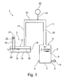
- the inventive device 1 for storing pourable or flowable products has a reservoir 2 for receiving the product and a siphon device 3.
- a bearing device 1 is schematically simplified and not to scale in Fig. 1 shown.
- the storage container 2 has a supply line 4, with which a product can be supplied to the storage container.
- the product is preferably pourable or flowable. It is especially a liquid.
- At the reservoir 2 opens a discharge line 5, with which the product can be removed from the reservoir 2.
- a feed pump 6 is arranged in the discharge line 5.
- the storage container 2 is typically formed as a stainless steel container with a bottom wall 7, side walls 8 and a top wall 9.
- a passage opening is provided, into which a connecting line 10 opens, which leads to the siphon device 3.
- the connecting line 10 extends with a first portion 11 of the top wall 9 of the reservoir 2 and then passes into a horizontal second section 12, from which then the connecting line 10 extends with a downwardly leading third portion 13 to the siphon 3.
- the siphon device 3 has a siphon container 14 with a bottom wall 15, side walls 16 and a top wall 17.
- the third portion 13 of the connecting line 10 opens at its lower end to the top wall 17 of the siphon container 14.
- the siphon container 14 is thus communicatively connected to the reservoir 2 via the connecting line 10.
- the siphon tank 14 is filled to a predetermined siphon level 18 with a siphon liquid.
- the siphon liquid is water, in particular a germ-free, preferably ionized water.
- a siphon tube 19 extends in the vertical direction through the top wall 17 of the siphon container 14 therethrough.
- the siphon tube 19 has a lower end 20 and an upper end 21.
- the lower end 20 is disposed below the siphon level 18.
- the upper end 21 is located outside the siphon tank 14 and ends in the atmosphere so that air can enter the siphon pipe 19 from above.
- a filter 22 is arranged at the upper end portion of the siphon tube 19.
- the filter 22 is a carbon filter that filters germs and bacteria from the air flowing through the siphon tube 19.
- An inert gas source 23 is connected to the connection line 10 by a line 24 for supplying to the device 1.
- the line 24 preferably opens at the highest point of the connecting line, when the inert gas is lighter than air, in order to displace air from the connecting line 10 and the reservoir 2 during commissioning can.
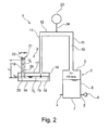
- Fig. 2 shows the storage device 1, wherein the gas in the reservoir 2, in the connecting line 10 and in the siphon container 14 has the maximum possible pressure.
- the space in the siphon container above the liquid level of the siphon liquid, in the connecting tube and in the reservoir above the product is filled with inert gas and, if necessary, air. Therefore, this space is referred to as gas space in the following.
- the level of the siphon liquid in the siphon container 14 is lowered relative to the siphon level 18. Part of the siphon liquid is pushed up by the pressure of the gas in the siphon tube 19. The siphon is lowered so far in the siphon tank 14 with the exception of the siphon tube 19, that the siphon mirror at the lower end 20 of the siphon tube 19 is located. This allows gas to enter through the lower end 20 into the siphon tube 19 and escape into the atmosphere. This is in Fig. 2 schematically represented by gas bubbles 25 in the siphon liquid in the siphon tube 19.
- the volume of the liquid V 1 received in the siphon tube 19 is equal to the volume of the symphonic liquid V 2 displaced in the siphon container 14 with the exception of the siphon tube 19.
- a predetermined height h 1 is established in the siphon tube 19 of the liquid column, which is defined by the cross-sectional area of the siphon tube 19 and the base area or cross-sectional area of the siphon container 14 and the distance between the siphon level 18 and the lower end 20 of the siphon tube 19.
- This height of the liquid column determines the maximum pressure which may be present in the gas contained in the storage device 1.
- the level of the siphon liquid is raised relative to the siphon level 18 to a predetermined height h 3 .
- the volume of the liquid V 3 displaced from the siphon tube 19 corresponds to the volume V 4 of the siphon liquid in the siphon container 14 with the exception of the siphon tube 19 in the region between the siphon level 18 and the siphon level at the height h 3 .
- This volume is determined by the parameters of the cross-sectional area of the siphon tube 19, the cross-sectional area of the siphon container 14, and the height between the siphon level 18 and the lower end 20 of the siphon tube 19.
- This volume correlates with the height h 3 , by which the level of the siphon liquid is raised relative to the siphon level 18.
- the height difference composed of the height h 3 and the height h 2 determines the maximum necessary pressure for supplying air from the atmosphere into the bearing device 1. Thus, the maximum negative pressure or minimum pressure in the bearing device 1 can be clearly determined by these parameters.
- the present embodiment is designed such that, in the event of overpressure, a liquid column h 1 in the siphon tube 19 adjusts to 458.7 mm. This corresponds to a pressure of 4500 Pa or 45 mbar (ü).
- the height h 3 is substantially smaller than the height h 2 , which is why approximately the height h 3 can be neglected.
- the height is set to 20.4 mm, whereby a maximum negative pressure of 200 Pa (2 mbar (g)) is effected.
- inert gas is supplied from the inert gas source 23 via the line 24 to the connecting line 10 and the storage container 2.
- the inert gas which is preferably lighter than air, displaces the air downwards.
- the discharge line 5 is opened in the reservoir 2, so that the air can escape to the outside. If the discharge line 5 is closed, then air is displaced from the connecting line and out of the siphon container through the siphon tube 19.
- the air contained in the storage device 1 can be almost completely displaced by the inert gas. However, it is not necessary that the siphon container 14, the air is completely displaced. It is completely sufficient that a boundary layer between the inert gas and the air in the region of the vertical third section 13 of the connecting line 10 is established. When pressure fluctuations due to a changing filling level in the reservoir 2, only the position of this interface changes in the region of the vertical, third portion 13 of the connecting line 10.
- the third portion 13 of the connecting line is formed with a large cross-section or as a large-volume hollow body, so that is ensured even with a gas exchange with the environment that the boundary layer between the inert gas and the air can not get out of the range of the vertical third portion 13 of the connecting line 10.
- Fig. 4 shows a siphon device 3 for a storage device according to the invention.
- the siphon container 14 has a bottom wall 15, side walls 16 and a top wall 17.
- the siphon tube 19 extends downwardly from the ceiling wall 17 and has a lower end 20 and an upper end 21.
- the upper end 21 is flush with the top wall 17 of the siphon container 14.
- a chamber 27 is provided which has the same cross-sectional area as the siphon container 14 and the side has an opening on which a pipe socket 28 is seated is open, so that atmospheric air can penetrate into the pipe socket 28.
- the filter (not shown in Fig. 4 ).
- a further pipe socket 29 is seated below the chamber 27, below the chamber 27, an opening is provided on the side wall 16 adjacent to the top wall 17, on which a further pipe socket 29 is seated.
- This pipe socket 29 is provided to be connected to a connecting line leading to a reservoir, so that gas can penetrate through the pipe socket 29 in the siphon container 14 at overpressure in the reservoir or at negative pressure in the reservoir gas from the siphon container 14 in can escape the reservoir.
- the siphon container 14 is filled with siphon liquid up to the siphon level 18.
- another pipe socket 30 opens the siphon 14, the one to a Lens 31 leads, through which the liquid level of the siphon liquid can be detected.
- Fig. 5 shows a further embodiment of a siphon device 3, similar to the siphon from Fig. 4 is formed, which is why the same parts are provided with the same reference numerals.
- the pipe socket 28 communicating with the atmosphere is formed on the upper ceiling wall and the chamber 27.
- the pipe socket 29 according to Fig. 4 omitted, since the siphon device 3 is disposed immediately adjacent to the reservoir 2 and communicates with this only via an opening 32.
- the connecting line of the embodiments explained above is omitted in this embodiment.
- Fig. 6 shows a further embodiment of a storage device according to the invention 1.
- the storage device according to Fig. 6 is similar to the one in Fig. 1 formed bearing device, which is why the same parts are designated by the same reference numerals and will not be explained again.
- This storage device has a siphon container 14, which in contrast to the embodiment of Fig. 1 However, here only serves as overpressure / vacuum safety valve.
- the inert gas source 23 is in the embodiment according to Fig. 6 connected via a respect to the connecting line 10 separately guided line 33 to the reservoir 2.
- a pressure reduction valve 34 is arranged, which reduces the existing pressure in the source 23 in the inert gas to the desired level in the reservoir 2 pressure level. It may also be appropriate to arrange two pressure reducing valves consecutively in the conduit 33 in order to gradually reduce the pressure.
- the reservoir 2 is connected to a further line 35 in which a pressure relief valve 36 is arranged.
- the pressure relief valve 36 is designed such that it opens automatically at a predetermined pressure in the reservoir 2 and gas can escape into the atmosphere.
- inert gas is thus added or removed to the storage container 2 as required.
- the siphon device 3 in this case forms an over / underpressure safety valve, if one of the valves in the lines 33, 35 in particular the pressure relief valve 36 should not work correctly.
- the siphon device 3 is a very simple, reliable and cost-effective safety valve that does not require power or has moving mechanical parts. Only the siphon level 18 must be checked at regular intervals.
- the embodiment according to Fig. 1 differs from the one after Fig. 6 in that the entire supply and removal of the inert gas takes place via the connecting line 10, wherein the siphon device at the same time the function of the safety valve and the pressure relief valve 36 has held.
- the embodiment according to Fig. 1 Above all, it is expedient if the amount of inert gas to be supplied and removed is rather small. For larger inert gas to be exchanged, the embodiment is after Fig. 6 advantageous.
Landscapes
- Engineering & Computer Science (AREA)
- General Engineering & Computer Science (AREA)
- Mechanical Engineering (AREA)
- Vacuum Packaging (AREA)
- Basic Packing Technique (AREA)
Applications Claiming Priority (1)
| Application Number | Priority Date | Filing Date | Title |
|---|---|---|---|
| DE201110116500 DE102011116500A1 (de) | 2011-10-20 | 2011-10-20 | Vorrichtung zum Lagern von schütt- oder fließfähigen Produkten |
Publications (2)
| Publication Number | Publication Date |
|---|---|
| EP2584232A2 true EP2584232A2 (fr) | 2013-04-24 |
| EP2584232A3 EP2584232A3 (fr) | 2014-04-09 |
Family
ID=47040520
Family Applications (1)
| Application Number | Title | Priority Date | Filing Date |
|---|---|---|---|
| EP12006989.3A Withdrawn EP2584232A3 (fr) | 2011-10-20 | 2012-10-09 | Dispositif de stockage de produits en vrac ou fluides |
Country Status (2)
| Country | Link |
|---|---|
| EP (1) | EP2584232A3 (fr) |
| DE (1) | DE102011116500A1 (fr) |
Cited By (2)
| Publication number | Priority date | Publication date | Assignee | Title |
|---|---|---|---|---|
| EP4080124A1 (fr) * | 2021-04-22 | 2022-10-26 | Hitachi Energy Switzerland AG | Cuve d'expansion pour un système de refroidissement |
| RU231042U1 (ru) * | 2024-05-31 | 2024-12-28 | Федеральное государственное бюджетное образовательное учреждение высшего образования "Саратовский государственный технический университет имени Гагарина Ю.А." | Гидравлический предохранительный клапан |
Family Cites Families (8)
| Publication number | Priority date | Publication date | Assignee | Title |
|---|---|---|---|---|
| US1563199A (en) * | 1920-11-11 | 1925-11-24 | Parkersburg Rig & Reel Co | Gas-tight steel tank |
| US1518486A (en) * | 1923-03-23 | 1924-12-09 | David F Youngblood | Relief device for oil tanks |
| FR2333726A1 (fr) * | 1975-12-01 | 1977-07-01 | Desrayaud Charles | Dispositif de securite pour cuves a vin et analogues |
| US4193967A (en) * | 1978-10-16 | 1980-03-18 | Merichem Company | Liquid sealing apparatus for sealing vapors in a tank |
| GB2215436A (en) * | 1988-02-29 | 1989-09-20 | Secr Defence | Pressure limitation method |
| US6199577B1 (en) * | 1999-03-12 | 2001-03-13 | Seh America, Inc. | Pressure relief system for chemical storage tanks |
| DE19951270C1 (de) * | 1999-10-25 | 2001-03-15 | Krupp Uhde Gmbh | Verfahren und Vorrichtung zur Beatmung von Tankanlagen |
| US8141577B2 (en) * | 2006-08-01 | 2012-03-27 | Franklin Fueling Systems, Inc. | Liquid filled pressure/vacuum valve for petroleum underground storage tanks |
-
2011
- 2011-10-20 DE DE201110116500 patent/DE102011116500A1/de not_active Withdrawn
-
2012
- 2012-10-09 EP EP12006989.3A patent/EP2584232A3/fr not_active Withdrawn
Non-Patent Citations (1)
| Title |
|---|
| None |
Cited By (2)
| Publication number | Priority date | Publication date | Assignee | Title |
|---|---|---|---|---|
| EP4080124A1 (fr) * | 2021-04-22 | 2022-10-26 | Hitachi Energy Switzerland AG | Cuve d'expansion pour un système de refroidissement |
| RU231042U1 (ru) * | 2024-05-31 | 2024-12-28 | Федеральное государственное бюджетное образовательное учреждение высшего образования "Саратовский государственный технический университет имени Гагарина Ю.А." | Гидравлический предохранительный клапан |
Also Published As
| Publication number | Publication date |
|---|---|
| DE102011116500A1 (de) | 2013-04-25 |
| EP2584232A3 (fr) | 2014-04-09 |
Similar Documents
| Publication | Publication Date | Title |
|---|---|---|
| DE3431107C2 (de) | Verfahren und Vorrichtung zum Füllen von Flaschen o.dgl. | |
| EP2307306B1 (fr) | Système de remplissage pour remplir des bouteilles ou récipients similaires et machine de remplissage correspondante | |
| AT391310B (de) | Einrichtung zum ausschank von unter druck stehenden getraenken, insbesondere bier | |
| EP0414075A1 (fr) | Dispositif de remplissage de récipients | |
| WO2011091956A1 (fr) | Procédé et système de remplissage sous pression de récipients | |
| EP2768762B1 (fr) | Procédé et machine de remplissage de bouteilles avec un produit à conditionner liquide | |
| EP1544156A1 (fr) | Tête de remplissage avec canal separé d'évacuation des gaz | |
| EP0081826A2 (fr) | Dispositif pour purger des condensats et similaires hors de systèmes sous pression | |
| DE3612453A1 (de) | Vorrichtung zur kultivierung von zellkulturen | |
| DE602005001543T2 (de) | Füllorgan mit ersetzbaren Ausläufen | |
| DE69316683T2 (de) | Flexibler innenbeutel für atmosphärischen behälter, dienend als verschluss der entlüftungsöffnung | |
| DE3913871A1 (de) | Kraftstofftank fuer kraftfahrzeuge und dergleichen | |
| DE102009035345A1 (de) | Tiefentnahmegerät für Flüssigkeitsproben | |
| EP2584232A2 (fr) | Dispositif de stockage de produits en vrac ou fluides | |
| DE102012201645A1 (de) | Ausdehnungs- und entgasungsvorrichtung zum anschluss an ein kreislaufsystem, insbesondere das kreislaufsystem einer gebäudeheizung | |
| DE1286458B (de) | OElspeichereinrichtung auf See | |
| EP2388311A1 (fr) | Réservoir de gaz | |
| AT509070B1 (de) | Vorrichtung und verfahren zum abfüllen von flüssigkeiten | |
| DE102008004426A1 (de) | Messvorrichtung und Messverfahren zur automatisierten Messung der Eigenschaften des in einer Biogasanlage befindlichen Faulschlamms | |
| EP4068955B1 (fr) | Alimentation en gaz co2 au moyen d'un récipient de gaz sous pression d'aquarium avec un substrat nutritif | |
| DE2435011C2 (de) | Einrichtung zum luftfreien Füllen und Verschließen von Transportbehältern für Bier, insbesondere von Bierflaschen | |
| EP1983240B1 (fr) | Agencement de soupape pour récipients | |
| DE102010046818B3 (de) | Fettpresse, insbesondere für eine Fettschmieranlage und Verfahren zum Zuführen von Fett zu einer mit Fett zu schmierenden Vorrichtung | |
| AT10126U1 (de) | Gärspund | |
| EP3345862B1 (fr) | Système de remplissage et procédé de remplissage de récipients cylindriques |
Legal Events
| Date | Code | Title | Description |
|---|---|---|---|
| PUAI | Public reference made under article 153(3) epc to a published international application that has entered the european phase |
Free format text: ORIGINAL CODE: 0009012 |
|
| AK | Designated contracting states |
Kind code of ref document: A2 Designated state(s): AL AT BE BG CH CY CZ DE DK EE ES FI FR GB GR HR HU IE IS IT LI LT LU LV MC MK MT NL NO PL PT RO RS SE SI SK SM TR |
|
| AX | Request for extension of the european patent |
Extension state: BA ME |
|
| PUAL | Search report despatched |
Free format text: ORIGINAL CODE: 0009013 |
|
| AK | Designated contracting states |
Kind code of ref document: A3 Designated state(s): AL AT BE BG CH CY CZ DE DK EE ES FI FR GB GR HR HU IE IS IT LI LT LU LV MC MK MT NL NO PL PT RO RS SE SI SK SM TR |
|
| AX | Request for extension of the european patent |
Extension state: BA ME |
|
| RIC1 | Information provided on ipc code assigned before grant |
Ipc: F16K 13/10 20060101AFI20140305BHEP Ipc: B65D 90/34 20060101ALI20140305BHEP Ipc: F16K 17/192 20060101ALI20140305BHEP |
|
| STAA | Information on the status of an ep patent application or granted ep patent |
Free format text: STATUS: THE APPLICATION IS DEEMED TO BE WITHDRAWN |
|
| 18D | Application deemed to be withdrawn |
Effective date: 20141010 |