EP2584342A1 - Procédé de mesures optiques quantitatives et appareil de laboratoire - Google Patents
Procédé de mesures optiques quantitatives et appareil de laboratoire Download PDFInfo
- Publication number
- EP2584342A1 EP2584342A1 EP11008334.2A EP11008334A EP2584342A1 EP 2584342 A1 EP2584342 A1 EP 2584342A1 EP 11008334 A EP11008334 A EP 11008334A EP 2584342 A1 EP2584342 A1 EP 2584342A1
- Authority
- EP
- European Patent Office
- Prior art keywords
- sample
- ref
- analyte
- light
- fix
- Prior art date
- Legal status (The legal status is an assumption and is not a legal conclusion. Google has not performed a legal analysis and makes no representation as to the accuracy of the status listed.)
- Granted
Links
Images


Classifications
-
- G—PHYSICS
- G01—MEASURING; TESTING
- G01N—INVESTIGATING OR ANALYSING MATERIALS BY DETERMINING THEIR CHEMICAL OR PHYSICAL PROPERTIES
- G01N21/00—Investigating or analysing materials by the use of optical means, i.e. using sub-millimetre waves, infrared, visible or ultraviolet light
- G01N21/62—Systems in which the material investigated is excited whereby it emits light or causes a change in wavelength of the incident light
- G01N21/63—Systems in which the material investigated is excited whereby it emits light or causes a change in wavelength of the incident light optically excited
- G01N21/64—Fluorescence; Phosphorescence
- G01N21/6486—Measuring fluorescence of biological material, e.g. DNA, RNA, cells
-
- G—PHYSICS
- G01—MEASURING; TESTING
- G01N—INVESTIGATING OR ANALYSING MATERIALS BY DETERMINING THEIR CHEMICAL OR PHYSICAL PROPERTIES
- G01N21/00—Investigating or analysing materials by the use of optical means, i.e. using sub-millimetre waves, infrared, visible or ultraviolet light
- G01N21/62—Systems in which the material investigated is excited whereby it emits light or causes a change in wavelength of the incident light
- G01N21/63—Systems in which the material investigated is excited whereby it emits light or causes a change in wavelength of the incident light optically excited
- G01N21/64—Fluorescence; Phosphorescence
- G01N21/6428—Measuring fluorescence of fluorescent products of reactions or of fluorochrome labelled reactive substances, e.g. measuring quenching effects, using measuring "optrodes"
-
- G—PHYSICS
- G01—MEASURING; TESTING
- G01N—INVESTIGATING OR ANALYSING MATERIALS BY DETERMINING THEIR CHEMICAL OR PHYSICAL PROPERTIES
- G01N21/00—Investigating or analysing materials by the use of optical means, i.e. using sub-millimetre waves, infrared, visible or ultraviolet light
- G01N21/62—Systems in which the material investigated is excited whereby it emits light or causes a change in wavelength of the incident light
- G01N21/63—Systems in which the material investigated is excited whereby it emits light or causes a change in wavelength of the incident light optically excited
- G01N21/64—Fluorescence; Phosphorescence
- G01N21/645—Specially adapted constructive features of fluorimeters
- G01N21/6452—Individual samples arranged in a regular 2D-array, e.g. multiwell plates
-
- G—PHYSICS
- G01—MEASURING; TESTING
- G01N—INVESTIGATING OR ANALYSING MATERIALS BY DETERMINING THEIR CHEMICAL OR PHYSICAL PROPERTIES
- G01N21/00—Investigating or analysing materials by the use of optical means, i.e. using sub-millimetre waves, infrared, visible or ultraviolet light
- G01N21/17—Systems in which incident light is modified in accordance with the properties of the material investigated
- G01N21/25—Colour; Spectral properties, i.e. comparison of effect of material on the light at two or more different wavelengths or wavelength bands
- G01N21/27—Colour; Spectral properties, i.e. comparison of effect of material on the light at two or more different wavelengths or wavelength bands using photo-electric detection ; circuits for computing concentration
- G01N21/274—Calibration, base line adjustment, drift correction
-
- G—PHYSICS
- G01—MEASURING; TESTING
- G01N—INVESTIGATING OR ANALYSING MATERIALS BY DETERMINING THEIR CHEMICAL OR PHYSICAL PROPERTIES
- G01N2201/00—Features of devices classified in G01N21/00
- G01N2201/06—Illumination; Optics
- G01N2201/062—LED's
-
- G—PHYSICS
- G01—MEASURING; TESTING
- G01N—INVESTIGATING OR ANALYSING MATERIALS BY DETERMINING THEIR CHEMICAL OR PHYSICAL PROPERTIES
- G01N2201/00—Features of devices classified in G01N21/00
- G01N2201/12—Circuits of general importance; Signal processing
- G01N2201/124—Sensitivity
-
- G—PHYSICS
- G01—MEASURING; TESTING
- G01N—INVESTIGATING OR ANALYSING MATERIALS BY DETERMINING THEIR CHEMICAL OR PHYSICAL PROPERTIES
- G01N2201/00—Features of devices classified in G01N21/00
- G01N2201/12—Circuits of general importance; Signal processing
- G01N2201/127—Calibration; base line adjustment; drift compensation
Definitions
- the invention relates to a method for quantitative optical measurements and a laboratory apparatus, which applies said method.
- Such methods are used, in particular, in chemical, biochemical, biological or biomedical laboratory environments to determine the concentration of chemical, biochemical, biological or biomedical analytes in sample solutions.
- a typical principle of such optical measurements is based on the measurement of fluorescent light.
- the analyte is marked by a fluorescence marker, which can be excited by the excitation light of a light source.
- the fluorescence marker receives the light and emits a sample light, typically at a different wavelength (fluorescence).
- the intensity of the detected sample light is used to derive the concentration of the analyte in the solution.
- the concentration of the analyte is proportional to the detected intensity and can be determined using a calibration factor.
- a calibration factor can be predetermined, e.g.
- Laboratory apparatus which use the measurement of fluorescence light are, for example, fluorometer, which determine the intensity of fluorescence sample light, fluorescence spectrometers, which determine the intensity of fluorescence sample light in dependence on the wavelength of the excitation light, or realtime PCR instruments, which monitor the progress of a polymerase chain reaction (PCR) by observing the fluorescent light from the PCR samples over the time.
- fluorometer which determine the intensity of fluorescence sample light
- fluorescence spectrometers which determine the intensity of fluorescence sample light in dependence on the wavelength of the excitation light
- realtime PCR instruments which monitor the progress of a polymerase chain reaction (PCR) by observing the fluorescent light from the PCR samples over the time.
- the electric photodetectors which are typically used as detector devices in laboratory apparatus for performing optical measurements, are limited to specific ranges of detectable light intensities for a predetermined set of operational parameters of the laboratory apparatus and, in particular, the detector device. Intensities within said ranges can be detected without changing the set of operational parameters.
- the set of operational parameters of the detector device has to be varied. Typically, electric gain is used to vary the sensitivity of a detector device. Alternatively, the intensity of the excitation light is varied to simulate a variation of the sensitivity parameter of the laboratory apparatus.
- sensitivity parameter which is suitable to measure the intensity of the incident sample light.
- the detector device automatically determines the - more or less correct - intensity in regard to the sensitivity parameter, which was applied during the measurement.
- the intensity I is proportional to the value of the sensitivity parameter S, at least in a substantially linear area of the function I(S).
- I(S) depends, as a rule, also on the wavelength, at which the sample light is detected by the detector device.
- the detector devices can use internal corrections to apply the correct relations between intensity and sensitivity.
- the correction may by valid for the detector device alone, but may need further modification when the detector device is part of a laboratory apparatus.
- a laboratory device the combination of a detector device with the measurement setup of a laboratory devices, including the light sources, filters, means for guiding the optical path will lead to a situation, where the use of different sensitivity parameters leads to a reduced accuracy of the intensities evaluated by the detector device.
- the accuracy of a comparison of the intensities, which are detected at different sensitivity parameters is reduced, because a precise calibration of the whole laboratory apparatus is missing.
- One possibility of increasing the accuracy of a comparison of the intensities, which are measured for different analytes, is to use only a single value of the sensitivity parameter for the operation of the detector device.
- the range of intensities, which can be detected by the detector device is limited by noise effects and signal saturation effects such that a small range only is available for the measurement.
- the optimal sensitivity parameter has to be found before, for example manually by the user.
- the method according to the invention is a method for the quantitative optical measurement of a characteristic property of at least one analyte in at least one laboratory sample, in particular for the fluorescence measurement of at least one biochemical or biological sample, the method using a laboratory apparatus, which has at least one light source and at least one detector device, the apparatus utilizing at least sensitivity parameter S, which controls the capability of the laboratory apparatus to detect a signal by means of the at lest one detector device, the method using source light for causing the at least one sample to emit a sample light, and the at least one detector device for detecting sample light and the method utilizing the at least one sensitivity parameter S to detect the corresponding at least one intensity I of the sample light, preferably utilizing at least two different sensitivity parameters S and detecting the corresponding at least two intensities I of the sample light, the method comprising the steps:
- the reference point preferably, is a standardization point, which preferably is the same for at least one analyte (or at least two analytes), which, in particular, is measured utilizing at least two different sensitivity parameters S. Furthermore, the reference point, preferably, is the same for at least one predetermined characteristical wavelength of detection. Preferably, one standardization point is used for each characteristical wavelength of detection.
- the quantity Q1 is the slope of a straight interpolation line or regression line, which is adapted to (S_m1; I_m1) and multiple reference points (S_n1, I_n1), which are determined using the same first analyte.
- the relation I(S) is considered to by dependent also on the characteristical wavelength of the sample light, which is detected by the detector device.
- the at least one sample is illuminated with source light, which has at least one characteristical wavelength ⁇ _s, which is the wavelength, where the source light intensity I( ⁇ _s) has a maximum.
- the source light can be monochromatic, which means, it emits light substantially only at the characteristical wavelength.
- the detector device can be equipped with optical filters to detect only one or more predetermined spectral region(s) around a characteristical wavelength ⁇ of detection, which preferably corresponds to the characteristical emission wavelength, at which the spectrum of sample light has a maximum. This emission wavelength can be defined by the fluorescence of an analyte.
- the method comprises the step to let the detector device detect the intensity of the sample light in dependence on at least one predetermined characteristical wavelength of detection, and wherein the at least one reference point(s) (S_ref; I_ref) is respectively determined in dependence on the characteristical wavelength of detection, thus assigning the at least one reference point(s) (S_ref; I_ref) to each characteristical wavelength of detection.
- the method is applied, preferably, in chemical, biochemical, biological or biomedical laboratories to determine a characteristic property of at least one analyte in at least one sample.
- the characteristic property is the concentration of an analyte, preferably a chemical, biochemical, biological or biomedical analyte, in a sample, preferably a chemical, biochemical, biological or biomedical sample.
- each sample having at least one analyte or exactly one analyte to be optically measured, preferably by a fluorescence measurement. It is also possible and preferred, that one sample is measured, which has two or more analytes to be measured.
- a laboratory apparatus for performing the method of the invention can be configured to hold one sample, which, for example, can be exchanged by the user by another sample to be measured, or to hold multiple samples, for measuring multiple samples arranged in the laboratory apparatus, in parallel or sequentially.
- the method provides that a specific sensitivity parameter is chosen, preferably automatically, preferably semi-automatically or preferably manually, for a specific concentration of the analyte in the sample, such that the sensitivity parameter allows to operate the detector device in a linear range, where the measured intensity I is substantially linear to the sensitivity parameter S.
- a specific sensitivity parameter is chosen, preferably automatically, preferably semi-automatically or preferably manually, for a specific concentration of the analyte in the sample, such that the sensitivity parameter allows to operate the detector device in a linear range, where the measured intensity I is substantially linear to the sensitivity parameter S.
- each sample with each analyte is measured with a specific sensitivity parameter.
- the concentration is derived from the slope C_m1 of a straight line, which runs through the reference point and the measured point (S_m1; I _ m1) or which is a regression line through multiple reference points and the measured point.
- a single standardization point (S_fix; I_fix), which preferably is determined prior to the measurement of the samples, is used for the measurement of different analytes, preferably in different samples, preferably for least at one predetermined characteristical wavelength of detection of the detector device, wherein preferably one individual standardization point (S_fix; I_fix) is assigned to one characteristical wavelength of detection.
- I_1(S) is determined by variation of S and detecting the associated intensity I_1(S).
- the dataset (S; I_1) should contain at least two points (S; I_1).
- the dataset (S; I_1) contains a plurality of points (S; I_1).
- the method of determining I_1 (S) can comprise a conventional regression or interpolation method for fitting a function I_1 (S) to the measured pairs of values (S; I_1).
- the standardization point (S_fix; I_fix) can be shared by all calculations C_m1, C_m2, C_m3, C_m4, ... C_mN of a measurement of a number of N (N>0) analytes. This further improves the overall accuracy of a comparison of different intensities, which are related to measurements at different sensitivity parameters S_m1, S_m2, S_m3, S_m4, ... S_mM, wherein M can be a number, which preferably is smaller than or equal to N.
- an optical standard sample is an optical sample, which is predetermined and representative for a certain concentration of an analyte, in particular representative for a certain concentration of a fluorescence marker.
- optical standard samples are available as a set of samples, wherein an optically interacting (e.g. by fluorescence) substance is contained in each sample with a different predetermined concentration.
- standard samples can be prepared by the user, e.g. by dissolving a sample analyte in a solution at different predetermined concentrations.
- the parameter c1 can be determined using a conventional calibration method.
- the method according to the invention comprises the further steps:
- the method according to the invention preferably comprises the further step of comparing the first sample value C_m1 and the second sample value C_m2 for determining a comparison value.
- a comparison can be performed, for example, by calculating a difference, for example, for receiving a result which is proportional to (C_m1 - C_m2). Further, a comparison can be performed, for example, by calculating a division operation, for example, for receiving a result which is proportional to (C_m1 / C_m2). Other comparison operations are possible.
- S_2_0 and I_2_0 are the parameters for defining the straight line, which can be determined using the dataset (S; I_2).
- I_2(S) is calculated by variation of S and detecting the associated intensity I_2(S).
- the method of determining I_2(S) can comprise a conventional regression or interpolation method for fitting a function I_2(S) to the measured pairs of values (S; I_2).
- I_2(S) the use of two straight lines I_1 (S) and I_2(S) has proved to achieve sufficient accuracy for a comparison operation of different intensities, measured for different analytes at different sensititvity parameters.
- the method of determining a standardization point comprises the steps:
- I_3(S) c3 * (S - S_3_0) + I_3_0, wherein c3 is a factor depending on the third optical standard sample, and which can be received by conventional calibration methods.
- S_3_0 and I_3_0 are the parameters for defining the straight line, which can be determined using the dataset (S; I_3).
- the method of determining I_3(S) can comprise a conventional regression or interpolation method for fitting a function I_3(S) to the measured pairs of values (S; I_3).
- any mathematical method can be used, preferably, which defines the intersection point to be an estimated intersection point.
- the mathematical estimation method can be a geometrical method, or a method which averages the coordinates of the intersection points of pairs of functions, or any other regression method.
- the mathematical estimation method provides the following steps:
- At least three or exactly three optical standard samples are used to determine three straight line functions I_1(S), I-2(S) and I_3(S), and wherein the mathematical estimation method provides the following steps:
- the method according to the invention comprises the modified steps of determining at least one reference point (S_ref; I_ref):
- the dataset can comprise two ore more points (S_mi; I_mi).
- the value C_m1 can further be derived from the slope of the straight line, which runs through multiple points (S_ni; I_ni) of measurements of the first analyte: preferably, multiple reference points are determined using the detected intensities I_n1 of the sample light assigned to the first analyte at different sensitivity parameters S_n1, wherein a conventional regression method is used to define a regression line through the measured point (S_m1; I_m1) and the multiple reference points (S_n1; I_n1), and wherein the first analyte value C_m1 is derived from the slope c_i of the regression line, wherein C_m1 is in particular proportional to c_i.
- C_m0 can be determined by performing a measurement of the background radiation, e.g.
- a background fluorescence measurement using the laboratory apparatus for performing the method, which contains the same sample holder, sample receptacle and preferably the solution, which solution is the same used for solving the analyte.
- the sample can be defined as the analyte with the solution, in which the analyte is solved.
- CON1 is proportional to C_m1 or to (C_m1 - C_m0).
- the sensitivity parameter can be understood to be any operational parameter of a laboratory apparatus, which has a detector device, which parameter controls the capability of the laboratory apparatus to detect a signal by means of a detector device.
- "sensitivity" of a sensor is defined as an output voltage change for a defined change in input.
- the sensitivity parameter is varied by variation of at least one operational parameter of the detector device, e.g. an electronic gain factor of an electrical detector device, e.g. a photometer.
- the sensitivity parameter is varied by variation of the intensity of the source light, which is used to measure the at least one analyte in the at least one sample.
- the value of the detected signal is increased, which means that the effect of increasing the intensity of the light source is equivalent to increasing the sensitivity of a sensor.
- the laboratory apparatus for quantitative optical measurements of a characteristic property of at least one analyte in at least one laboratory sample, in particular fluorescence measurements of at least one biochemical or biological sample, comprising at least one light source for illuminating the at least one sample with source light, at least one detector device for detecting sample light, and an electric control device, wherein the electric control device is configured to at least automatically calculate in dependence on Q1, using the method according to the invention or one of its preferred embodiments, the first analyte value C_m1, which is characteristic for a property of the first analyte, in particular for a concentration of the first analyte in the at least one sample.
- the method according to the invention is implemented by the apparatus or the control device, preferably by utilizing a computer program code, which preferably is stored on a memory device, e.g. optical data disc or a flash memory.
- a laboratory apparatus according to the invention is configured to store said computer program code in a data memory of the laboratory apparatus.
- said computer program code is executable and the laboratory apparatus according to the invention is configured to execute the computer program code for applying the method according to the invention.
- the laboratory apparatus according to the invention is configured to be a fluorometer, or a fluorescence spectrometer, or a realtime PCR instrument.
- Other preferred method steps can be derived from the description of the functions of the laboratory apparatus according to the invention.
- the laboratory apparatus preferably comprises other components, e.g. a sample holder area for accommodating a sample holder, for holding at least one sample vessel, in particular for holding single vessels, e.g. sample tubes, capped or uncapped, or for holding multiple sample receptacles, e.g. microtiter plates or PCR-plates, user interfaces, e.g. a keyboard, display or a touchscreen, data exchange interfaces and connections.
- the laboratory apparatus, in particular the sample holder can comprise temperature devices, e.g. Peltier elements, for heating and/or cooling the sample holder, and/or thermosen-sors.
- the laboratory apparatus and the electric control device can comprise electric control loops for controlling the temperature of the sample holder or the samples, respectively.
- the laboratory apparatus is configured to apply a temperature program to the sample holder, e.g. for repeatedly adjust the temperature of the sample holder through different temperature levels (thermal cycling).
- the laboratory apparatus is configured to be a thermocycler for performing realtime PCR.
- a preferred use of the method according to the invention or the laboratory apparatus according to the invention is to optically measure the fluorescence light of biochemical samples or biological samples, in particular PCR samples.
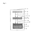
- Fig. 1 a laboratory device 1 according to the invention, which is configured to apply the method 10, which is shown in Fig. 2 .
- the laboratory apparatus is a fluorescence spectrometer 1 for performing fluorescence measurements of multiple biochemical or biological samples, e.g. PCR-samples.
- the laboratory apparatus has a light source 2, which is configured to emit light at one excitation wavelength of 470 nm, in the case of the embodiment, in particular to emit the light 3 to a first sample 5 within a sample holder 4, and to subsequently or simultaneously emit light 3' to each analyte in each sample of the sample holder.
- the embodiment of the laboratory apparatus works in the same way, if only one sample receptacle is provided, which contains two reagents.
- the laboratory apparatus further comprises the detector device 7, which has at least one photodetector 8 for detecting the sample lights 6, 6', and for providing electrical signals, which quantify the intensity of a sample light 6, 6'.
- the detector device 7 is a commercial FluoSens-module, QIAGEN GmbH, Germany.
- the sensitivity parameter of the FluoSens-module can be changed by controlling the intensity of light sources (LED which emit the excitation light).
- the photodetector has two characteristical wavelengths of detection, which are 520 nm and 560 nm, in the embodiment.
- the detector device or the laboratory apparatus have an electric control device 9.
- the electric control device 9 preferably, comprises a microprocessor, or at least a CPU and memory, in particular RAM and solid memory.
- the electric control device is configured, preferably, for applying the method according to the invention, in particular the method 10 or 20.
- the electric control device comprises programmable circuits, which are programmed to perform the method according to the invention.
- Said programming can be a software programming, which uses a computer program code.
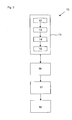
- Fig. 2 shows a flow diagram of the method 10 for the quantitative fluorescence measurements of at least one biochemical or biological sample 5.
- the typical task is to determine the concentrations of multiple analytes in multiple separate samples or one single sample and to accurately compare the determined concentrations.
- the method 10 is suitable to achieve a sufficient accuracy of such a measurement with subsequent comparison of the detected concentrations of the analytes.
- the method 10 is run automatically by the laboratory apparatus 1 and provides said accurate measurements without any substantial additional user interaction, which is comfortable for the user and increases the efficiency of the work flow in a laboratory.
- the method 10 provides an adjustment step 11 of the laboratory apparatus.
- Said adjustment provides the use of three optical standard samples, e.g. user prepared standard samples, for determining the reference point (S_ref; I_ref) in step 11, which is a standardization point (S_fix; I_fix).
- the single standardization point (S_fix; I_fix) is used to accurately determine the measured quantities C_m1 ... C_mN of multiple analytes, using multiple sensitivity parameters S_m1 ... S_mM.
- S_fix; I_fix two standardization points (S_fix; I_fix)-1 and (S_fix; I_fix)-2 are determined (not shown), wherein (S_fix; I_-fix)-1 is determined using the characteristical wavelength of 520 nm of the detector device for detecting only light at 520 nm (i.e. within a rather narrow spectrum around 520 nm), and (S_fix; I_fix)-2 is determined using the characteristical wavelength of 560 nm.
- the following steps are described for the measurement at 520 nm and have to be repeated for measuring at 560 nm, in the embodiment.
- a first dataset of multiple points (S_1; I_1) is determined, at the characteristical wavelength of 520 nm. This means that for the first optical standard sample a predetermined light intensity is illuminating the samples, and the excited sample light is detected by the detector device, while using multiple (at least two) different sensitivity parameters S_1. For each value of S_1, the intensity I_1 of the sample light is detected, measured and stored. The resulting dataset is graphically shown in the diagram of Fig. 3a .
- a first straight line I_1 (S) is fitted through the points of said dataset.
- two points of the dataset are sufficient to draw a line.
- Said estimation method can be conventional, using a conventional curve fitting method to fit a straight line through (or between) the points of the dataset, e.g. a fitting method using least squares approximation.
- at least (and/or a maximum of) 2, 3, 4, 5, 6, 7, 8, 9, 10, 11, 12, 13, 14, 15, 20, 25, 30, 35, 40, 50 or a different number of points are used for determining the dataset, which efficiently defines the straight line.
- additionally algorithms are provided for sorting out outliers, which occur due to noise or signal saturation.
- a second dataset of multiple points (S_2; I_2) is determined.
- S_2; I_2 the predetermined light intensity is illuminating the sample, and the excited sample light is detected by the detector device (at the same characteristical wavelengths), while using multiple (at least two) different sensitivity parameters S_2.
- S_2 the intensity I_2 of the sample light is detected, measured and stored.
- the resulting dataset is graphically shown in the diagram of Fig. 3b , in addition to the dataset (S_1; I_1).
- a third dataset of multiple points (S_3; I_3) is determined.
- S_3 the predetermined light intensity is illuminating the samples, and the excited sample light is detected by the detector device (at the same characteristical wavelengths), while using multiple (at least two) different sensitivity parameters S_3.
- S_3 the intensity I_3 of the sample light is detected, measured and stored.
- the resulting dataset is graphically shown in the diagram of Fig. 3c , in addition to the data-sets (S_1; I_1) and (S_2; I_2).
- step 15 of the determination of the standardization point the three intersection points IS1, IS2, IS3 of the three pairs of straight lines (I_1(S); I_2(S)), (I_2(S); I_3(S)), and (I_1(S); I_3(S)) are determined.
- the standardization point is determined to be the intersection point of the bisecting lines of the three angles of the triangle defined by the three intersection points IS1, IS2, IS3.
- the size of the area of the triangle can be used to evaluate the quality factor of the method of determining the standardization point.
- the intersection point is determined numerically, e.g. by the electric control device of a laboratory apparatus.
- the sensitivity S_m1 is automatically determined, which is suitable to measure the intensity of the sample light, which is assigned to the first analyte to be measured.
- the measurement starts with a default value of S_m1 and determines I_m1.
- a table e.g. the table in Fig. 4
- the step 16 automatically is repeated with another value of S_m1, until a valid value S_m1 is found.
- the intensity I_m1, which is associated to the valid value of S_m1 is stored.
- C_m1 is the slope of the straight line, which runs through the two points (S_fix; I_fix) and (S_m1; I_m1). This is graphically shown in Fig. 5 .
- a conventional calibration method can comprise the steps of providing a set of samples, which each contain a sample analyte in a predetermined concentration, and by recording the intensities, which correspond to the sample, in particular using a standard source light, which can have standard intensity, standard frequency, preferably using standard illumination and/or detection times and/or a standard output energy of the light source.
- the method steps 16 to 18 can be repeated for multiple samples and multiple analytes, using the same or another standardization point (S_fix; I_fix), for one of the characteristical wavelengths of detection or for multiple wavelength, to receive accurate results of the measurements, which can be accurately compared by calculation steps, in particular.
- S_fix standardization point
- I_fix standardization point
- Fig. 6 the alternative embodiment of the method according to the invention is shown, namely the method 20.
- the reference point is calculated in step 21 using the sample with the first analyte, instead of utilizing an optical standard sample.
- the method is preferably run at only one wavelength of detection, but can also be run once for each characteristical wavelength of detection.
- Method 20 comprises the step 22 of using at least one further sample light assigned to the first analyte for letting the detector device detect at least one reference light from the sample, by determining a dataset with the points (S_m1; I_m1) and (S_m2; I_m2) with pairs of the measured intensity I_m1 (I_m2)in dependence from the variable sensitivity parameter S_m1 (S_m2).
- the values S_m1, S_m2 are determined such that "valid" values of I_m1, I_m2 are detected, e.g. by using a table as shown in Fig.
- the two points are used, in step 23, to derive C_m1 as the slope of the straight line, which runs through the two points (S_m1; I_m1) and (S_m2; I_m2). This is graphically shown in Fig. 7 .
- a is a factor or function, which is predetermined by a conventional calibration method
- C_m0 the result of a measurement of the background fluorescence.
- multiple reference points S_n1; I_n1 can be used to even more precisely define the straight line and to derive the slope using conventional regression methods, which leads to a more precise measurement of CON1.
- the same method 20 can be applied to each analyte.
Landscapes
- Health & Medical Sciences (AREA)
- Immunology (AREA)
- Physics & Mathematics (AREA)
- Chemical & Material Sciences (AREA)
- Life Sciences & Earth Sciences (AREA)
- General Physics & Mathematics (AREA)
- Biochemistry (AREA)
- General Health & Medical Sciences (AREA)
- Analytical Chemistry (AREA)
- Nuclear Medicine, Radiotherapy & Molecular Imaging (AREA)
- Pathology (AREA)
- Optics & Photonics (AREA)
- Chemical Kinetics & Catalysis (AREA)
- Engineering & Computer Science (AREA)
- Biomedical Technology (AREA)
- Molecular Biology (AREA)
- Investigating, Analyzing Materials By Fluorescence Or Luminescence (AREA)
- Apparatus Associated With Microorganisms And Enzymes (AREA)
- Measuring Or Testing Involving Enzymes Or Micro-Organisms (AREA)
Priority Applications (5)
| Application Number | Priority Date | Filing Date | Title |
|---|---|---|---|
| EP11008334.2A EP2584342B1 (fr) | 2011-10-17 | 2011-10-17 | Procédé de mesures optiques quantitatives et appareil de laboratoire |
| PCT/EP2012/004328 WO2013056820A1 (fr) | 2011-10-17 | 2012-10-16 | Procédé de mesures optiques quantitatives et appareil de laboratoire |
| JP2014536136A JP5956587B2 (ja) | 2011-10-17 | 2012-10-16 | 定量的な光学的測定のための方法及び実験機器 |
| CN201280049653.8A CN103890564B (zh) | 2011-10-17 | 2012-10-16 | 用于定量光学测量的方法和实验室设备 |
| US14/352,031 US20140370509A1 (en) | 2011-10-17 | 2012-10-16 | Method for Quantitative Optical Measurements and Laboratory Apparatus |
Applications Claiming Priority (1)
| Application Number | Priority Date | Filing Date | Title |
|---|---|---|---|
| EP11008334.2A EP2584342B1 (fr) | 2011-10-17 | 2011-10-17 | Procédé de mesures optiques quantitatives et appareil de laboratoire |
Publications (2)
| Publication Number | Publication Date |
|---|---|
| EP2584342A1 true EP2584342A1 (fr) | 2013-04-24 |
| EP2584342B1 EP2584342B1 (fr) | 2020-03-18 |
Family
ID=45715007
Family Applications (1)
| Application Number | Title | Priority Date | Filing Date |
|---|---|---|---|
| EP11008334.2A Active EP2584342B1 (fr) | 2011-10-17 | 2011-10-17 | Procédé de mesures optiques quantitatives et appareil de laboratoire |
Country Status (5)
| Country | Link |
|---|---|
| US (1) | US20140370509A1 (fr) |
| EP (1) | EP2584342B1 (fr) |
| JP (1) | JP5956587B2 (fr) |
| CN (1) | CN103890564B (fr) |
| WO (1) | WO2013056820A1 (fr) |
Cited By (1)
| Publication number | Priority date | Publication date | Assignee | Title |
|---|---|---|---|---|
| US11561162B2 (en) | 2018-03-19 | 2023-01-24 | Sony Corporation | Information processing device, information processing system, and information processing method |
Families Citing this family (7)
| Publication number | Priority date | Publication date | Assignee | Title |
|---|---|---|---|---|
| WO2014038681A1 (fr) * | 2012-09-07 | 2014-03-13 | 国立大学法人京都大学 | Electrode pour pile primaire ou pile secondaire siège d'une réaction locale régulée, et pile primaire ou secondaire l'utilisant |
| EP2974656A1 (fr) * | 2014-07-14 | 2016-01-20 | Universität Zürich | Dispositif pour mesurer la concentration d'un analyte dans le sang ou les tissus d'un animal ou un humain, en particulier un enfant prématuré, avec un étalonnage automatique |
| US9945788B2 (en) * | 2015-02-06 | 2018-04-17 | Life Technologies Corporation | Methods and systems for determining optical regions of interest |
| RU2017131053A (ru) * | 2015-02-06 | 2019-03-12 | Лайф Текнолоджиз Корпорейшн | Способы и системы для нормирования приборов с помощью чистого красителя |
| CN112384130B (zh) * | 2018-06-28 | 2024-08-30 | 贝克顿·迪金森公司 | 用于标准化血液培养测量系统中的信号的系统和方法 |
| WO2020133257A1 (fr) * | 2018-12-28 | 2020-07-02 | 深圳迈瑞生物医疗电子股份有限公司 | Procédé de traitement de valeur de détection d'un objet en cours de mesure, analyseur d'hémocytes et support d'informations |
| CN121816504A (zh) | 2023-09-01 | 2026-04-07 | 艾本德欧洲股份有限公司 | 用于检测荧光的液体处理装置和方法 |
Citations (4)
| Publication number | Priority date | Publication date | Assignee | Title |
|---|---|---|---|---|
| US6075613A (en) * | 1999-02-26 | 2000-06-13 | General Scanning, Inc. | Optical scanner calibration device |
| US20030105195A1 (en) * | 2001-12-04 | 2003-06-05 | Holcomb Nelson R. | Devices for calibrating optical scanners and methods of using the same |
| EP1431745A1 (fr) * | 2002-12-20 | 2004-06-23 | Becton Dickinson and Company | Dispositif et procédés pour analyser une pluralité de colorants fluorescents en utilisant une pluralité de photodétecteurs à gain réglable |
| US20040217271A1 (en) * | 2001-06-25 | 2004-11-04 | Staton Kenneth L. | Scanning system with calibrated detection and method |
Family Cites Families (7)
| Publication number | Priority date | Publication date | Assignee | Title |
|---|---|---|---|---|
| JPH0758263B2 (ja) * | 1988-08-26 | 1995-06-21 | 株式会社日立製作所 | 自動蛍光光度計を用いる分析方法 |
| JPH1123467A (ja) * | 1997-06-30 | 1999-01-29 | Suzuki Motor Corp | 蛍光量測定装置 |
| US6078390A (en) * | 1998-05-04 | 2000-06-20 | General Scanning, Inc. | Scanning system and method of operation for automatically setting detection sensitivity |
| US6316774B1 (en) * | 1998-08-18 | 2001-11-13 | Molecular Devices Corporation | Optical system for a scanning fluorometer |
| JP3793729B2 (ja) * | 2002-02-13 | 2006-07-05 | 株式会社日立ハイテクノロジーズ | 蛍光画像検出方法及びその装置並びにdna検査方法及びその装置 |
| EP1394716A1 (fr) * | 2002-08-07 | 2004-03-03 | Université Libre de Bruxelles-Hôpital Erasme | Méthode, système et logiciel pour éviter la saturation de signaux dans la quantification de microréseaux de polynucléotides |
| JP5279481B2 (ja) * | 2008-12-25 | 2013-09-04 | 株式会社日立ハイテクノロジーズ | 核酸分析装置 |
-
2011
- 2011-10-17 EP EP11008334.2A patent/EP2584342B1/fr active Active
-
2012
- 2012-10-16 CN CN201280049653.8A patent/CN103890564B/zh active Active
- 2012-10-16 US US14/352,031 patent/US20140370509A1/en not_active Abandoned
- 2012-10-16 WO PCT/EP2012/004328 patent/WO2013056820A1/fr not_active Ceased
- 2012-10-16 JP JP2014536136A patent/JP5956587B2/ja not_active Expired - Fee Related
Patent Citations (4)
| Publication number | Priority date | Publication date | Assignee | Title |
|---|---|---|---|---|
| US6075613A (en) * | 1999-02-26 | 2000-06-13 | General Scanning, Inc. | Optical scanner calibration device |
| US20040217271A1 (en) * | 2001-06-25 | 2004-11-04 | Staton Kenneth L. | Scanning system with calibrated detection and method |
| US20030105195A1 (en) * | 2001-12-04 | 2003-06-05 | Holcomb Nelson R. | Devices for calibrating optical scanners and methods of using the same |
| EP1431745A1 (fr) * | 2002-12-20 | 2004-06-23 | Becton Dickinson and Company | Dispositif et procédés pour analyser une pluralité de colorants fluorescents en utilisant une pluralité de photodétecteurs à gain réglable |
Cited By (1)
| Publication number | Priority date | Publication date | Assignee | Title |
|---|---|---|---|---|
| US11561162B2 (en) | 2018-03-19 | 2023-01-24 | Sony Corporation | Information processing device, information processing system, and information processing method |
Also Published As
| Publication number | Publication date |
|---|---|
| JP2014534430A (ja) | 2014-12-18 |
| JP5956587B2 (ja) | 2016-07-27 |
| WO2013056820A1 (fr) | 2013-04-25 |
| EP2584342B1 (fr) | 2020-03-18 |
| CN103890564A (zh) | 2014-06-25 |
| US20140370509A1 (en) | 2014-12-18 |
| CN103890564B (zh) | 2016-12-14 |
Similar Documents
| Publication | Publication Date | Title |
|---|---|---|
| EP2584342B1 (fr) | Procédé de mesures optiques quantitatives et appareil de laboratoire | |
| RU2702577C2 (ru) | Системы и способы для биологического анализа | |
| CN102985807B (zh) | 流式粒子分析装置以及流式粒子分析方法 | |
| US9677934B2 (en) | Background correction in emission spectra | |
| EP2813839A1 (fr) | Procédé d'étalonnage de photométrie | |
| EP3182096B1 (fr) | Étalonnage et/ou détection d'erreurs dans un dispositif de mesure optique pour des échantillons biologiques | |
| EP3091350B1 (fr) | Analyseur d'échantillons et procédé d'analyse d'échantillons | |
| JP2008209350A (ja) | 血液凝固時間測定装置 | |
| US10856391B2 (en) | Method to correct signal light intensities measured by a detector of a detection unit in a laboratory instrument | |
| JP5209705B2 (ja) | 自動分析装置 | |
| CN113707219A (zh) | 用于分析核酸扩增反应的分析方法和系统 | |
| US10458997B2 (en) | Signal offset determination and correction | |
| WO2014175363A1 (fr) | Dispositif et procédé de mesure de concentration en composant | |
| AU2023259524A1 (en) | Methods and devices for obtaining silicon photomultiplier data. | |
| WO2010034017A2 (fr) | Systèmes et procédés de normalisation de signaux par diffusion raman | |
| CN106018364A (zh) | 一种植物油的判别方法 | |
| JP6314872B2 (ja) | 含有蛍光成分数決定方法及びその含有蛍光成分数決定方法を用いた分光蛍光光度計 | |
| WO2025221849A1 (fr) | Analyseur de réactif et procédé d'étalonnage de l'analyseur de réactif | |
| CN106461557B (zh) | 一种用于检测样本井所含的样本的设备和方法 | |
| JP2011117747A (ja) | シリカ濃度測定装置及びシリカ濃度測定方法 |
Legal Events
| Date | Code | Title | Description |
|---|---|---|---|
| PUAI | Public reference made under article 153(3) epc to a published international application that has entered the european phase |
Free format text: ORIGINAL CODE: 0009012 |
|
| AK | Designated contracting states |
Kind code of ref document: A1 Designated state(s): AL AT BE BG CH CY CZ DE DK EE ES FI FR GB GR HR HU IE IS IT LI LT LU LV MC MK MT NL NO PL PT RO RS SE SI SK SM TR |
|
| AX | Request for extension of the european patent |
Extension state: BA ME |
|
| 17P | Request for examination filed |
Effective date: 20130826 |
|
| RBV | Designated contracting states (corrected) |
Designated state(s): AL AT BE BG CH CY CZ DE DK EE ES FI FR GB GR HR HU IE IS IT LI LT LU LV MC MK MT NL NO PL PT RO RS SE SI SK SM TR |
|
| STAA | Information on the status of an ep patent application or granted ep patent |
Free format text: STATUS: EXAMINATION IS IN PROGRESS |
|
| 17Q | First examination report despatched |
Effective date: 20180821 |
|
| GRAP | Despatch of communication of intention to grant a patent |
Free format text: ORIGINAL CODE: EPIDOSNIGR1 |
|
| STAA | Information on the status of an ep patent application or granted ep patent |
Free format text: STATUS: GRANT OF PATENT IS INTENDED |
|
| RIC1 | Information provided on ipc code assigned before grant |
Ipc: G01N 21/64 20060101AFI20190325BHEP Ipc: G01N 21/27 20060101ALN20190325BHEP |
|
| INTG | Intention to grant announced |
Effective date: 20190423 |
|
| GRAJ | Information related to disapproval of communication of intention to grant by the applicant or resumption of examination proceedings by the epo deleted |
Free format text: ORIGINAL CODE: EPIDOSDIGR1 |
|
| STAA | Information on the status of an ep patent application or granted ep patent |
Free format text: STATUS: EXAMINATION IS IN PROGRESS |
|
| GRAP | Despatch of communication of intention to grant a patent |
Free format text: ORIGINAL CODE: EPIDOSNIGR1 |
|
| STAA | Information on the status of an ep patent application or granted ep patent |
Free format text: STATUS: GRANT OF PATENT IS INTENDED |
|
| INTC | Intention to grant announced (deleted) | ||
| RIC1 | Information provided on ipc code assigned before grant |
Ipc: G01N 21/64 20060101AFI20190909BHEP Ipc: G01N 21/27 20060101ALN20190909BHEP |
|
| INTG | Intention to grant announced |
Effective date: 20190930 |
|
| GRAS | Grant fee paid |
Free format text: ORIGINAL CODE: EPIDOSNIGR3 |
|
| GRAA | (expected) grant |
Free format text: ORIGINAL CODE: 0009210 |
|
| STAA | Information on the status of an ep patent application or granted ep patent |
Free format text: STATUS: THE PATENT HAS BEEN GRANTED |
|
| AK | Designated contracting states |
Kind code of ref document: B1 Designated state(s): AL AT BE BG CH CY CZ DE DK EE ES FI FR GB GR HR HU IE IS IT LI LT LU LV MC MK MT NL NO PL PT RO RS SE SI SK SM TR |
|
| REG | Reference to a national code |
Ref country code: GB Ref legal event code: FG4D |
|
| REG | Reference to a national code |
Ref country code: DE Ref legal event code: R096 Ref document number: 602011065624 Country of ref document: DE |
|
| REG | Reference to a national code |
Ref country code: AT Ref legal event code: REF Ref document number: 1246480 Country of ref document: AT Kind code of ref document: T Effective date: 20200415 Ref country code: IE Ref legal event code: FG4D |
|
| PG25 | Lapsed in a contracting state [announced via postgrant information from national office to epo] |
Ref country code: RS Free format text: LAPSE BECAUSE OF FAILURE TO SUBMIT A TRANSLATION OF THE DESCRIPTION OR TO PAY THE FEE WITHIN THE PRESCRIBED TIME-LIMIT Effective date: 20200318 Ref country code: NO Free format text: LAPSE BECAUSE OF FAILURE TO SUBMIT A TRANSLATION OF THE DESCRIPTION OR TO PAY THE FEE WITHIN THE PRESCRIBED TIME-LIMIT Effective date: 20200618 Ref country code: FI Free format text: LAPSE BECAUSE OF FAILURE TO SUBMIT A TRANSLATION OF THE DESCRIPTION OR TO PAY THE FEE WITHIN THE PRESCRIBED TIME-LIMIT Effective date: 20200318 |
|
| REG | Reference to a national code |
Ref country code: NL Ref legal event code: MP Effective date: 20200318 |
|
| PG25 | Lapsed in a contracting state [announced via postgrant information from national office to epo] |
Ref country code: GR Free format text: LAPSE BECAUSE OF FAILURE TO SUBMIT A TRANSLATION OF THE DESCRIPTION OR TO PAY THE FEE WITHIN THE PRESCRIBED TIME-LIMIT Effective date: 20200619 Ref country code: BG Free format text: LAPSE BECAUSE OF FAILURE TO SUBMIT A TRANSLATION OF THE DESCRIPTION OR TO PAY THE FEE WITHIN THE PRESCRIBED TIME-LIMIT Effective date: 20200618 Ref country code: HR Free format text: LAPSE BECAUSE OF FAILURE TO SUBMIT A TRANSLATION OF THE DESCRIPTION OR TO PAY THE FEE WITHIN THE PRESCRIBED TIME-LIMIT Effective date: 20200318 Ref country code: SE Free format text: LAPSE BECAUSE OF FAILURE TO SUBMIT A TRANSLATION OF THE DESCRIPTION OR TO PAY THE FEE WITHIN THE PRESCRIBED TIME-LIMIT Effective date: 20200318 Ref country code: LV Free format text: LAPSE BECAUSE OF FAILURE TO SUBMIT A TRANSLATION OF THE DESCRIPTION OR TO PAY THE FEE WITHIN THE PRESCRIBED TIME-LIMIT Effective date: 20200318 |
|
| REG | Reference to a national code |
Ref country code: LT Ref legal event code: MG4D |
|
| PG25 | Lapsed in a contracting state [announced via postgrant information from national office to epo] |
Ref country code: NL Free format text: LAPSE BECAUSE OF FAILURE TO SUBMIT A TRANSLATION OF THE DESCRIPTION OR TO PAY THE FEE WITHIN THE PRESCRIBED TIME-LIMIT Effective date: 20200318 |
|
| PG25 | Lapsed in a contracting state [announced via postgrant information from national office to epo] |
Ref country code: CZ Free format text: LAPSE BECAUSE OF FAILURE TO SUBMIT A TRANSLATION OF THE DESCRIPTION OR TO PAY THE FEE WITHIN THE PRESCRIBED TIME-LIMIT Effective date: 20200318 Ref country code: PT Free format text: LAPSE BECAUSE OF FAILURE TO SUBMIT A TRANSLATION OF THE DESCRIPTION OR TO PAY THE FEE WITHIN THE PRESCRIBED TIME-LIMIT Effective date: 20200812 Ref country code: RO Free format text: LAPSE BECAUSE OF FAILURE TO SUBMIT A TRANSLATION OF THE DESCRIPTION OR TO PAY THE FEE WITHIN THE PRESCRIBED TIME-LIMIT Effective date: 20200318 Ref country code: EE Free format text: LAPSE BECAUSE OF FAILURE TO SUBMIT A TRANSLATION OF THE DESCRIPTION OR TO PAY THE FEE WITHIN THE PRESCRIBED TIME-LIMIT Effective date: 20200318 Ref country code: SM Free format text: LAPSE BECAUSE OF FAILURE TO SUBMIT A TRANSLATION OF THE DESCRIPTION OR TO PAY THE FEE WITHIN THE PRESCRIBED TIME-LIMIT Effective date: 20200318 Ref country code: LT Free format text: LAPSE BECAUSE OF FAILURE TO SUBMIT A TRANSLATION OF THE DESCRIPTION OR TO PAY THE FEE WITHIN THE PRESCRIBED TIME-LIMIT Effective date: 20200318 Ref country code: IS Free format text: LAPSE BECAUSE OF FAILURE TO SUBMIT A TRANSLATION OF THE DESCRIPTION OR TO PAY THE FEE WITHIN THE PRESCRIBED TIME-LIMIT Effective date: 20200718 Ref country code: SK Free format text: LAPSE BECAUSE OF FAILURE TO SUBMIT A TRANSLATION OF THE DESCRIPTION OR TO PAY THE FEE WITHIN THE PRESCRIBED TIME-LIMIT Effective date: 20200318 |
|
| REG | Reference to a national code |
Ref country code: AT Ref legal event code: MK05 Ref document number: 1246480 Country of ref document: AT Kind code of ref document: T Effective date: 20200318 |
|
| REG | Reference to a national code |
Ref country code: DE Ref legal event code: R097 Ref document number: 602011065624 Country of ref document: DE |
|
| PLBE | No opposition filed within time limit |
Free format text: ORIGINAL CODE: 0009261 |
|
| STAA | Information on the status of an ep patent application or granted ep patent |
Free format text: STATUS: NO OPPOSITION FILED WITHIN TIME LIMIT |
|
| PG25 | Lapsed in a contracting state [announced via postgrant information from national office to epo] |
Ref country code: DK Free format text: LAPSE BECAUSE OF FAILURE TO SUBMIT A TRANSLATION OF THE DESCRIPTION OR TO PAY THE FEE WITHIN THE PRESCRIBED TIME-LIMIT Effective date: 20200318 Ref country code: AT Free format text: LAPSE BECAUSE OF FAILURE TO SUBMIT A TRANSLATION OF THE DESCRIPTION OR TO PAY THE FEE WITHIN THE PRESCRIBED TIME-LIMIT Effective date: 20200318 Ref country code: IT Free format text: LAPSE BECAUSE OF FAILURE TO SUBMIT A TRANSLATION OF THE DESCRIPTION OR TO PAY THE FEE WITHIN THE PRESCRIBED TIME-LIMIT Effective date: 20200318 Ref country code: ES Free format text: LAPSE BECAUSE OF FAILURE TO SUBMIT A TRANSLATION OF THE DESCRIPTION OR TO PAY THE FEE WITHIN THE PRESCRIBED TIME-LIMIT Effective date: 20200318 |
|
| 26N | No opposition filed |
Effective date: 20201221 |
|
| PG25 | Lapsed in a contracting state [announced via postgrant information from national office to epo] |
Ref country code: PL Free format text: LAPSE BECAUSE OF FAILURE TO SUBMIT A TRANSLATION OF THE DESCRIPTION OR TO PAY THE FEE WITHIN THE PRESCRIBED TIME-LIMIT Effective date: 20200318 |
|
| PG25 | Lapsed in a contracting state [announced via postgrant information from national office to epo] |
Ref country code: SI Free format text: LAPSE BECAUSE OF FAILURE TO SUBMIT A TRANSLATION OF THE DESCRIPTION OR TO PAY THE FEE WITHIN THE PRESCRIBED TIME-LIMIT Effective date: 20200318 |
|
| REG | Reference to a national code |
Ref country code: CH Ref legal event code: PL |
|
| PG25 | Lapsed in a contracting state [announced via postgrant information from national office to epo] |
Ref country code: MC Free format text: LAPSE BECAUSE OF FAILURE TO SUBMIT A TRANSLATION OF THE DESCRIPTION OR TO PAY THE FEE WITHIN THE PRESCRIBED TIME-LIMIT Effective date: 20200318 Ref country code: LU Free format text: LAPSE BECAUSE OF NON-PAYMENT OF DUE FEES Effective date: 20201017 |
|
| REG | Reference to a national code |
Ref country code: BE Ref legal event code: MM Effective date: 20201031 |
|
| PG25 | Lapsed in a contracting state [announced via postgrant information from national office to epo] |
Ref country code: CH Free format text: LAPSE BECAUSE OF NON-PAYMENT OF DUE FEES Effective date: 20201031 Ref country code: BE Free format text: LAPSE BECAUSE OF NON-PAYMENT OF DUE FEES Effective date: 20201031 Ref country code: LI Free format text: LAPSE BECAUSE OF NON-PAYMENT OF DUE FEES Effective date: 20201031 |
|
| PG25 | Lapsed in a contracting state [announced via postgrant information from national office to epo] |
Ref country code: IE Free format text: LAPSE BECAUSE OF NON-PAYMENT OF DUE FEES Effective date: 20201017 |
|
| PG25 | Lapsed in a contracting state [announced via postgrant information from national office to epo] |
Ref country code: TR Free format text: LAPSE BECAUSE OF FAILURE TO SUBMIT A TRANSLATION OF THE DESCRIPTION OR TO PAY THE FEE WITHIN THE PRESCRIBED TIME-LIMIT Effective date: 20200318 Ref country code: MT Free format text: LAPSE BECAUSE OF FAILURE TO SUBMIT A TRANSLATION OF THE DESCRIPTION OR TO PAY THE FEE WITHIN THE PRESCRIBED TIME-LIMIT Effective date: 20200318 Ref country code: CY Free format text: LAPSE BECAUSE OF FAILURE TO SUBMIT A TRANSLATION OF THE DESCRIPTION OR TO PAY THE FEE WITHIN THE PRESCRIBED TIME-LIMIT Effective date: 20200318 |
|
| PG25 | Lapsed in a contracting state [announced via postgrant information from national office to epo] |
Ref country code: MK Free format text: LAPSE BECAUSE OF FAILURE TO SUBMIT A TRANSLATION OF THE DESCRIPTION OR TO PAY THE FEE WITHIN THE PRESCRIBED TIME-LIMIT Effective date: 20200318 Ref country code: AL Free format text: LAPSE BECAUSE OF FAILURE TO SUBMIT A TRANSLATION OF THE DESCRIPTION OR TO PAY THE FEE WITHIN THE PRESCRIBED TIME-LIMIT Effective date: 20200318 |
|
| REG | Reference to a national code |
Ref country code: FR Ref legal event code: PLFP Year of fee payment: 12 |
|
| REG | Reference to a national code |
Ref country code: DE Ref legal event code: R081 Ref document number: 602011065624 Country of ref document: DE Owner name: EPPENDORF SE, DE Free format text: FORMER OWNER: EPPENDORF AG, 22339 HAMBURG, DE |
|
| P01 | Opt-out of the competence of the unified patent court (upc) registered |
Effective date: 20230527 |
|
| PGFP | Annual fee paid to national office [announced via postgrant information from national office to epo] |
Ref country code: GB Payment date: 20231020 Year of fee payment: 13 |
|
| PGFP | Annual fee paid to national office [announced via postgrant information from national office to epo] |
Ref country code: FR Payment date: 20231025 Year of fee payment: 13 Ref country code: DE Payment date: 20231020 Year of fee payment: 13 |
|
| REG | Reference to a national code |
Ref country code: DE Ref legal event code: R119 Ref document number: 602011065624 Country of ref document: DE |
|
| GBPC | Gb: european patent ceased through non-payment of renewal fee |
Effective date: 20241017 |
|
| PG25 | Lapsed in a contracting state [announced via postgrant information from national office to epo] |
Ref country code: DE Free format text: LAPSE BECAUSE OF NON-PAYMENT OF DUE FEES Effective date: 20250501 |
|
| PG25 | Lapsed in a contracting state [announced via postgrant information from national office to epo] |
Ref country code: GB Free format text: LAPSE BECAUSE OF NON-PAYMENT OF DUE FEES Effective date: 20241017 |
|
| PG25 | Lapsed in a contracting state [announced via postgrant information from national office to epo] |
Ref country code: FR Free format text: LAPSE BECAUSE OF NON-PAYMENT OF DUE FEES Effective date: 20241031 |