EP2585164B1 - Système de raccordement pour tuyau à deux lumières - Google Patents
Système de raccordement pour tuyau à deux lumières Download PDFInfo
- Publication number
- EP2585164B1 EP2585164B1 EP11733999.4A EP11733999A EP2585164B1 EP 2585164 B1 EP2585164 B1 EP 2585164B1 EP 11733999 A EP11733999 A EP 11733999A EP 2585164 B1 EP2585164 B1 EP 2585164B1
- Authority
- EP
- European Patent Office
- Prior art keywords
- pipe
- cones
- lumen
- internal
- cone
- Prior art date
- Legal status (The legal status is an assumption and is not a legal conclusion. Google has not performed a legal analysis and makes no representation as to the accuracy of the status listed.)
- Active
Links
Images
Classifications
-
- F—MECHANICAL ENGINEERING; LIGHTING; HEATING; WEAPONS; BLASTING
- F16—ENGINEERING ELEMENTS AND UNITS; GENERAL MEASURES FOR PRODUCING AND MAINTAINING EFFECTIVE FUNCTIONING OF MACHINES OR INSTALLATIONS; THERMAL INSULATION IN GENERAL
- F16L—PIPES; JOINTS OR FITTINGS FOR PIPES; SUPPORTS FOR PIPES, CABLES OR PROTECTIVE TUBING; MEANS FOR THERMAL INSULATION IN GENERAL
- F16L39/00—Joints or fittings for double-walled or multi-channel pipes or pipe assemblies
- F16L39/005—Joints or fittings for double-walled or multi-channel pipes or pipe assemblies for concentric pipes
-
- A—HUMAN NECESSITIES
- A61—MEDICAL OR VETERINARY SCIENCE; HYGIENE
- A61M—DEVICES FOR INTRODUCING MEDIA INTO, OR ONTO, THE BODY; DEVICES FOR TRANSDUCING BODY MEDIA OR FOR TAKING MEDIA FROM THE BODY; DEVICES FOR PRODUCING OR ENDING SLEEP OR STUPOR
- A61M3/00—Medical syringes, e.g. enemata; Irrigators
- A61M3/02—Enemata; Irrigators
- A61M3/0279—Cannula; Nozzles; Tips; their connection means
-
- A—HUMAN NECESSITIES
- A61—MEDICAL OR VETERINARY SCIENCE; HYGIENE
- A61M—DEVICES FOR INTRODUCING MEDIA INTO, OR ONTO, THE BODY; DEVICES FOR TRANSDUCING BODY MEDIA OR FOR TAKING MEDIA FROM THE BODY; DEVICES FOR PRODUCING OR ENDING SLEEP OR STUPOR
- A61M39/00—Tubes, tube connectors, tube couplings, valves, access sites or the like, specially adapted for medical use
- A61M39/10—Tube connectors; Tube couplings
- A61M39/1011—Locking means for securing connection; Additional tamper safeties
-
- A—HUMAN NECESSITIES
- A61—MEDICAL OR VETERINARY SCIENCE; HYGIENE
- A61M—DEVICES FOR INTRODUCING MEDIA INTO, OR ONTO, THE BODY; DEVICES FOR TRANSDUCING BODY MEDIA OR FOR TAKING MEDIA FROM THE BODY; DEVICES FOR PRODUCING OR ENDING SLEEP OR STUPOR
- A61M39/00—Tubes, tube connectors, tube couplings, valves, access sites or the like, specially adapted for medical use
- A61M39/10—Tube connectors; Tube couplings
- A61M39/105—Multi-channel connectors or couplings, e.g. for connecting multi-lumen tubes
Definitions
- the present invention relates to a connecting system for a pipe with two lumina.
- connection devices for pipes with several coaxial lumina are e.g. known from US 2003/028182 A1 , WO 2009/081178 A1 , US 5,681,063 A , EP 0 082 950 A2 and US 2002/0160640 A1 .
- Different applications can particularly require the simultaneous passage of a liquid, such as water, and a gas, such as air, through the same pipe.
- a pipe could be used, which has a first lumen situated along an axis and being limited by a cylindrical wall, serving to conduct water, the wall having a second lumen, cylindrical or non-cylindrical, which is used for the passage of air.
- This type of pipe makes it difficult to connect two sections of the pipe, or to connect an inlet section of the pipe to a device, particularly in the case where the connection has to be established without taking into account the angular orientation of the two parts, one in relation to the other, a round the axis of the pipe.
- a pipe provided with two lumina is sometimes used, for example, with an anal irrigation probe.
- an inflatable balloon must first of all be filled with air in order to position the probe in the rectum and to keep it there. The probe then allows the instillation of water for washing the rectum.
- a tank allows the pipe to be supplied with water and a pump with compressed air, but the probe itself is for single use, and a new probe must be connected to the pipe for each new session of colon cleansing.
- a quick and simple connecting device is therefore advantageous, and this all the more so since these probes are often used by paraplegic or tetraplegic patients, whose dexterity is limited. It is therefore desirable to be able to connect the probe to the end of the inlet pipe with maximum ease, without having to take into account the angular orientation of the said pipe in relation to the probe.
- the objective of the present invention is to create a connecting system for a pipe with two lumina, allowing simple connection without taking into account the angular orientation of the parts to connect.
- the objective is achieved in accordance with the invention by a connecting system according to claim 1.
- the present disclosure relates to a connecting system in two parts, for a pipe with a first lumen in the axis of the pipe, and a second lumen outside of the axis of the pipe, the first part having two coaxial cones as connecting elements, the first lumen leading to the first internal cone, and the second lumen leading to the space present between the first cone and the second cone.
- the second part of the connecting system has two coaxial cones as connecting elements, which are complementary to the two cones of the first part, the two cones of the first part co-operating in a water and/or airtight manner with the two cones of the second part, in order to establish a water and/or airtight continuity between the two lumina of the first and second part, respectively.
- the connecting system according to the invention is composed of two parts, of which one can be connected to a pipe with two lumina, and the other can either also be connected to a pipe with two lumina, or to a device such as an anal probe, which functions by means of two different fluids, air and water, for example.
- the first part of the connecting system has an internal, conical connecting element.
- the second part of the connecting system has a complementary cone, which, when the system is connected, co-operates in such a way with the cone of the first part that a water and/or airtight effect is obtained.
- the first lumen of the pipe which follows the axis of the latter, leads to the internal cone of the first part of the connecting system.
- the first part of the connecting system furthermore has an external cone positioned in a concentric manner in relation to the first, internal cone. A space therefore emerges between the internal and external cone, to which leads the second lumen of the pipe, which is situated outside of the axis.
- the second part of the connecting system has a cone which is complementary to the second cone of the first part, which, when it is connected, co-operates in such a way with the cone of the first part that a water and/or airtight effect is obtained.
- the external cones of the two parts of the connecting system thus close in a water and/or airtight manner the space between the internal and external cones, so that the fluid conducted through the second lumen of the pipe can thus progress into the corresponding opening of the other piece without loss or leak.
- the cones of the first part of the connecting system can have a diameter which decreases in the direction of the second part, in such a way that they can be inserted into the respective complementary cones of the second part during connection.
- the inverse embodiment is also possible, according to which, the cones of the second part can be inserted into the cones of the first part.
- a cone of one of the parts can also be inserted into the complementary cone of the second part, and the second cone can incorporate its complementary cone.
- At least one of two complementary connecting elements is made of elastically deformable material.
- the elastically deformable connecting element can thus be slightly deformed, in particular slightly expanded or squeezed when the complementary connecting element is connected, and the water and/or airtight effect is enhanced.
- This can for example be realized by using an elastically deformable material for one of the two parts of the connecting system, whereas the other part can be made of rigid material.
- both parts can be made of elastically deformable material, or any other combination is possible with at least one of two complementary connecting elements being elastically deformable.
- the first part of the connecting device can have two other coaxial connecting elements, of which at least one has a conical shape.
- the internal connection element is conical with increasing diameter which, and if the external connection element is cylindrical, the pipe can be slid against the internal conical connection element.
- the pipe is thus slightly widened by the cone, that is to say, its internal surface is applied against the internal cone, and thus its internal diameter is slightly increased, and a water and/or airtight effect is obtained.
- the widening of the internal diameter of the pipe leads to pressure of its external wall on the external cylindrical connecting element, so that the connection becomes fully water and/or airtight.
- the first lumen of the pipe leads to the internal cone, which communicates with the internal connecting cone of the second part of the connecting system.
- the second lumen of the pipe which is situated in the wall of the pipe, leads to a space situated between the two connecting elements.
- the internal connecting elements of the first part can preferably be maintained in the external connecting elements in a coaxial manner by means of connecting struts. Consequently, there is a space between the two cones, guaranteeing that the medium coming from the second lumen can run freely through the first part of the connecting device.
- connection of the first and second parts of the connecting system is preferably strengthened by a snap connection when the parts are connected.
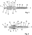
- Figure 1 shows an anal probe 14 with a supply system for water for intestinal cleansing and with an entry system for air to inflate the balloons 15 disposed at the level of the probe.
- the water supply operates along the axis A of the probe, the balloons 15 are divided in segments around the probe 14; they are shown non-inflated on the Figure and are adjacent to the probe. Consequently, the air inlet operates in an off-central manner.
- a pipe 3 is used to bring water, which pipe has a first cylindrical lumen 4 along its axis A which is limited by a wall 16.
- the wall 16 of the pipe 3 has a second lumen 5 serving for the passage of air.
- the pipe 3 is connected to the first part 1 of a connecting device in accordance with the invention, which consists of two parts 1, 2.
- the second part 2 of the connecting device is directly linked to the anal probe 14.
- the connecting device 1, 2 could alternatively be linked to other equipment or to another pipe, for example for creating an extension.
- the first part 1 of the connecting device on the connecting side towards the second part 2, has two coaxial cones 6, 7.
- the first lumen 4 of the pipe 3 of the water supply system leads to the internal cone 6.
- the second lumen 5 of the air supply system leads to the space 8 situated between the internal cone 6 and the external cone 7.
- the second part 2 of the connecting device has two coaxial cones 9, 10, which are complementary to the cones 6, 7 of the first part.
- the dimensions of the cones are such that, in order to connect the two parts of the connecting device, the two cones of the first part co-operate in a water and airtight manner with the two cones of the second part.
- the second part 2 is made of elastically deformable material, and the dimension of the cones 9, 10 are such that they are slightly expanded when the cones 6, 7 of the first part are inserted into them, and form a water and airtight connection when the device is in the connected position.
- the first part 1 of the connecting device also has two coaxial connecting elements 11, 12, both having conical shape in the example in this figure.
- the diameter of the internal cone 11 increases, whereas that of the external cone 12 reduces.
- the pipe 3 can thus be tightened with the central lumen 4 in a water and airtight manner against the internal cone 11.
- the external cone 12 surrounds external wall 16 of the pipe 3 in a water and airtight manner, in such a way that the lumen 5 situated in the wall 16 of the pipe 3 leads to the space 17 between the cones 11, 12.
- the internal connecting element comprising the two cones 11 and 6 is kept in the external connecting element comprising the cones 12 and 7. This is preferably achieved by means of connecting struts 22.
- the intermediary space 17 between the cones 11 and 12 and the intermediary space 8 between the cones 6 and 7 can thus communicate with one another. The air arriving through the lumen 5 of the pipe 3 into the intermediary space 17 is thus lead into the first part 1 of the connecting system.
- Figure 2 shows the embodiment from Figure 1 in the connected position. It can be seen that the two internal cones 6, 9 are inserted in such a way that the water of the central lumen 4 of the pipe 3 circulates through the lumen 18 of the probe and can flow through the orifices 19.
- the space 8 between the internal cone 6 and the external cone 7 of the first part 1 of the connecting device is closed by the connecting elements 9, 10 of the first part, so that the air which comes out here through the lumen 5 of the pipe 3 is transported by the channel 20 of the probe 14 and inflates the balloon 15 situated on the probe 14.
- connection of the two parts 1, 2 of the connecting system is strengthened by means of a snap mechanism 13, 14. Pressure on the push-button 21 allows for the assembly to be released, releasing the teeth 14 in the groove 13 of the second part 2 for separating the two parts 1, 2.
Landscapes
- Health & Medical Sciences (AREA)
- Heart & Thoracic Surgery (AREA)
- Engineering & Computer Science (AREA)
- General Health & Medical Sciences (AREA)
- Veterinary Medicine (AREA)
- Hematology (AREA)
- Life Sciences & Earth Sciences (AREA)
- Animal Behavior & Ethology (AREA)
- Anesthesiology (AREA)
- Public Health (AREA)
- Biomedical Technology (AREA)
- Pulmonology (AREA)
- General Engineering & Computer Science (AREA)
- Mechanical Engineering (AREA)
- Surgical Instruments (AREA)
- Infusion, Injection, And Reservoir Apparatuses (AREA)
- Endoscopes (AREA)
- Quick-Acting Or Multi-Walled Pipe Joints (AREA)
- Pipe Accessories (AREA)
Claims (9)
- Système de raccord à deux pièces (1, 2) destiné à un tuyau (3) comprenant une première lumière (4) dans l'axe (A) du tuyau et une seconde lumière (5) dans la paroi (16) du tuyau,
la première pièce (1) présentant comme éléments de raccord deux cônes coaxiaux (6, 7), la première lumière (4) menant au premier cône interne (6) et la seconde lumière (5) à l'espace (8) présent entre le premier cône (6) et le second cône (7), la seconde pièce (2) présentant comme éléments de raccord deux cônes coaxiaux (9, 10) complémentaires aux deux cônes (6, 7) de la première pièce (1),
les deux cônes (6, 7) de la première pièce (1) coopérant de manière étanche à l'eau et/ou à l'air avec les deux cônes (9, 10) de la seconde pièce (2) afin de raccorder les deux pièces (1, 2)
caractérisé en ce que
la première pièce a un élément de raccord interne (11) et un élément de raccord externe (12) pour raccorder le tuyau (3), lesdits éléments de raccord interne et externe (11, 12) étant coaxiaux, en ce que l'élément de raccord externe (12) est adapté pour entourer la paroi externe (16) du tuyau (3) de manière étanche à l'eau et à l'air de sorte que la lumière (5) située dans la paroi (16) du tuyau (3) mène à l'espace (17) entre les éléments de raccord (11,12), et en ce que au moins l'élément de raccord interne (11) est de forme conique. - Système de raccord selon la revendication 1, caractérisé en ce que les cônes (6, 7) de la première pièce (1) peuvent être insérés de manière étanche à l'air et /ou à l'eau dans les deux cônes (9, 10) de la seconde pièce (2).
- Système de raccord selon la revendication 1, caractérisé en ce que les cônes (9, 10) de la seconde pièce (2) peuvent être insérés de manière étanche à l'air et/ou à l'eau dans les deux cônes (6, 7) de la première pièce (1).
- Système de raccord selon l'une des revendications 1 à 3, caractérisé en ce que au moins un des deux éléments de raccord complémentaires (6, 9 ; 7, 10) sont fait en matériau élastiquement déformable.
- Système de raccord selon l'une des revendications 1 à 4, caractérisé en ce que l'élément de raccord interne (11) est de forme conique et de diamètre croissant.
- Système de raccord selon l'une des revendications 1 à 5, caractérisé en ce que l'élément de raccord externe (12) est de forme conique et de diamètre décroissant.
- Système de raccord selon l'une des revendications 1 à 5, caractérisé en ce que l'élément de raccord externe (12) est de forme cylindrique.
- Système de raccord selon l'une des revendications 1 à 7, caractérisé en ce que les éléments de raccord internes (6, 11) de la première pièce (1) sont maintenus de manière coaxiale dans les éléments de raccord externes (7, 12) de la première pièce au moyen de traverses de jonction (22).
- Système de raccord selon l'une des revendications 1 à 8, caractérisé en ce que la première pièce (1) et la seconde pièce (2) sont consolidées en position raccordée par l'intermédiaire d'un assemblage par encliquetage (13, 14).
Applications Claiming Priority (2)
| Application Number | Priority Date | Filing Date | Title |
|---|---|---|---|
| FR1002638A FR2961886B1 (fr) | 2010-06-23 | 2010-06-23 | Systeme de raccord a deux pieces destine a un tuyau a deux lumieres |
| PCT/EP2011/003089 WO2011160834A1 (fr) | 2010-06-23 | 2011-06-22 | Système de raccordement pour tuyau à deux lumières |
Publications (2)
| Publication Number | Publication Date |
|---|---|
| EP2585164A1 EP2585164A1 (fr) | 2013-05-01 |
| EP2585164B1 true EP2585164B1 (fr) | 2021-02-17 |
Family
ID=43502962
Family Applications (1)
| Application Number | Title | Priority Date | Filing Date |
|---|---|---|---|
| EP11733999.4A Active EP2585164B1 (fr) | 2010-06-23 | 2011-06-22 | Système de raccordement pour tuyau à deux lumières |
Country Status (10)
| Country | Link |
|---|---|
| US (1) | US20130099476A1 (fr) |
| EP (1) | EP2585164B1 (fr) |
| JP (1) | JP2013533016A (fr) |
| CN (1) | CN103328036A (fr) |
| DK (1) | DK2585164T3 (fr) |
| ES (1) | ES2868374T3 (fr) |
| FR (1) | FR2961886B1 (fr) |
| PT (1) | PT2585164T (fr) |
| RU (1) | RU2601682C2 (fr) |
| WO (1) | WO2011160834A1 (fr) |
Families Citing this family (3)
| Publication number | Priority date | Publication date | Assignee | Title |
|---|---|---|---|---|
| DK3593831T3 (da) | 2016-07-08 | 2023-10-16 | Hollister Inc | Væsketilførsel til en legemshuleirrigationsindretning |
| EP3532126B1 (fr) * | 2016-10-28 | 2021-03-10 | MBH-International A/S | Ensemble comprenant un cathéter et un composant d'accouplement pour accoupler le cathéter à des tubes, et appareil comprenant l'ensemble |
| NL2020013B1 (en) * | 2017-12-04 | 2019-06-11 | Crea Ip B V | Multi-lumen luer connector |
Citations (1)
| Publication number | Priority date | Publication date | Assignee | Title |
|---|---|---|---|---|
| US20020160640A1 (en) * | 2000-02-23 | 2002-10-31 | Nikolai Korpan | Connection assembly for conduits |
Family Cites Families (17)
| Publication number | Priority date | Publication date | Assignee | Title |
|---|---|---|---|---|
| US3588149A (en) * | 1969-08-13 | 1971-06-28 | Amp Inc | Vacuum or pressure coupling devices |
| DE2907832C2 (de) * | 1979-02-28 | 1984-05-17 | Fresenius AG, 6380 Bad Homburg | Verbindungseinrichtung zum Anschluß von Kanülen, Kathetern, Infusionsnadeln oder Schläuchen |
| JPS5794790U (fr) * | 1980-12-02 | 1982-06-10 | ||
| JPS5886133A (ja) * | 1981-11-19 | 1983-05-23 | オリンパス光学工業株式会社 | 内視鏡用送液装置 |
| CH653426A5 (de) * | 1981-11-26 | 1985-12-31 | Karrer Weber & Cie Ag | Verbindungsvorrichtung fuer sanitaerinstallationen mit flexibler, beiderends anschlussmittel aufweisender verbindungsleitung. |
| NL9002816A (nl) * | 1990-12-19 | 1992-07-16 | Single Buoy Moorings | Snelkoppeling en snelkoppelsamenstel. |
| US5810768A (en) * | 1995-06-07 | 1998-09-22 | Icu Medical, Inc. | Medical connector |
| US5681063A (en) * | 1995-11-28 | 1997-10-28 | E.R. Squibb & Sons, Inc. | Connector assembly for double tubing |
| DE19823177A1 (de) * | 1998-05-23 | 1999-11-25 | Bosch Gmbh Robert | Vorrichtung zum Verbinden zweier Teile |
| US20030028182A1 (en) * | 1999-04-21 | 2003-02-06 | Cryocath Technologies Inc. | Cryoablation catheter handle |
| GB9926538D0 (en) * | 1999-11-09 | 2000-01-12 | Kci Medical Ltd | Multi-lumen connector |
| DK1556125T3 (da) * | 2002-10-23 | 2006-12-27 | Coloplast As | En koblingsindretning |
| US20050015075A1 (en) * | 2003-07-14 | 2005-01-20 | B & D Research And Development Inc. | Coupling device for medical lines |
| US8002313B2 (en) * | 2006-04-25 | 2011-08-23 | Kci Licensing, Inc. | Inline swivel connection for multi-lumen tubing |
| US9057468B2 (en) * | 2007-11-27 | 2015-06-16 | Covidien Lp | Wedge coupling |
| GB0724790D0 (en) * | 2007-12-20 | 2008-01-30 | Smith & Nephew | Connectors |
| US8708376B2 (en) * | 2008-10-10 | 2014-04-29 | Deka Products Limited Partnership | Medium connector |
-
2010
- 2010-06-23 FR FR1002638A patent/FR2961886B1/fr active Active
-
2011
- 2011-06-22 DK DK11733999.4T patent/DK2585164T3/da active
- 2011-06-22 CN CN2011800404870A patent/CN103328036A/zh active Pending
- 2011-06-22 EP EP11733999.4A patent/EP2585164B1/fr active Active
- 2011-06-22 RU RU2013104313/14A patent/RU2601682C2/ru active
- 2011-06-22 WO PCT/EP2011/003089 patent/WO2011160834A1/fr not_active Ceased
- 2011-06-22 ES ES11733999T patent/ES2868374T3/es active Active
- 2011-06-22 JP JP2013515768A patent/JP2013533016A/ja active Pending
- 2011-06-22 US US13/806,758 patent/US20130099476A1/en not_active Abandoned
- 2011-06-22 PT PT117339994T patent/PT2585164T/pt unknown
Patent Citations (1)
| Publication number | Priority date | Publication date | Assignee | Title |
|---|---|---|---|---|
| US20020160640A1 (en) * | 2000-02-23 | 2002-10-31 | Nikolai Korpan | Connection assembly for conduits |
Also Published As
| Publication number | Publication date |
|---|---|
| RU2013104313A (ru) | 2014-07-27 |
| PT2585164T (pt) | 2021-05-10 |
| FR2961886A1 (fr) | 2011-12-30 |
| US20130099476A1 (en) | 2013-04-25 |
| WO2011160834A1 (fr) | 2011-12-29 |
| CN103328036A (zh) | 2013-09-25 |
| RU2601682C2 (ru) | 2016-11-10 |
| FR2961886B1 (fr) | 2012-08-10 |
| JP2013533016A (ja) | 2013-08-22 |
| EP2585164A1 (fr) | 2013-05-01 |
| DK2585164T3 (da) | 2021-05-10 |
| ES2868374T3 (es) | 2021-10-21 |
Similar Documents
| Publication | Publication Date | Title |
|---|---|---|
| US9402979B2 (en) | Releasable torque device | |
| US5836967A (en) | Catheter assembly | |
| US5578016A (en) | Stopcock | |
| US9089363B2 (en) | Arthroscopic cannula dams for fluid control | |
| JP2008511414A5 (fr) | ||
| CN103402573A (zh) | 具有抗变形的导丝管腔的窄轮廓导液管 | |
| EP2585164B1 (fr) | Système de raccordement pour tuyau à deux lumières | |
| US20160303310A1 (en) | Suction-irrigation head | |
| JP2005535380A5 (fr) | ||
| JP6654140B2 (ja) | 医療用コネクタ | |
| EP3020444B1 (fr) | Cathéter | |
| US10426935B2 (en) | Reinforced syringe body | |
| EP2341972B1 (fr) | Structure de cathéter | |
| US20100106051A1 (en) | Single lumen catheter with separate tubes therein | |
| CN110454978B (zh) | 进水装置及热水器 | |
| JP2015536757A5 (fr) | ||
| CN105476670B (zh) | 一种管径可调节的鞘管 | |
| CN207356061U (zh) | 一种内窥镜用外套管 | |
| CN208591446U (zh) | 一种气动式血管扩张器 | |
| EP3067119B1 (fr) | Appareil d'éjection de fluide à grande distance | |
| CN212438547U (zh) | 一种可变多通道管及可变内窥镜 | |
| CN121243518B (zh) | 一种自调节胸腔引流管 | |
| CN218106563U (zh) | 一种新型三腔导尿管 | |
| CN204563046U (zh) | 一种用于胸腔引流瓶的多功能转换接头 | |
| CN212679067U (zh) | 一种多通道管及多通道内窥镜 |
Legal Events
| Date | Code | Title | Description |
|---|---|---|---|
| PUAI | Public reference made under article 153(3) epc to a published international application that has entered the european phase |
Free format text: ORIGINAL CODE: 0009012 |
|
| 17P | Request for examination filed |
Effective date: 20130122 |
|
| AK | Designated contracting states |
Kind code of ref document: A1 Designated state(s): AL AT BE BG CH CY CZ DE DK EE ES FI FR GB GR HR HU IE IS IT LI LT LU LV MC MK MT NL NO PL PT RO RS SE SI SK SM TR |
|
| DAX | Request for extension of the european patent (deleted) | ||
| 17Q | First examination report despatched |
Effective date: 20140303 |
|
| STAA | Information on the status of an ep patent application or granted ep patent |
Free format text: STATUS: EXAMINATION IS IN PROGRESS |
|
| REG | Reference to a national code |
Ref country code: DE Ref legal event code: R079 Ref document number: 602011070127 Country of ref document: DE Free format text: PREVIOUS MAIN CLASS: A61M0039100000 Ipc: A61M0003020000 |
|
| GRAP | Despatch of communication of intention to grant a patent |
Free format text: ORIGINAL CODE: EPIDOSNIGR1 |
|
| STAA | Information on the status of an ep patent application or granted ep patent |
Free format text: STATUS: GRANT OF PATENT IS INTENDED |
|
| RIC1 | Information provided on ipc code assigned before grant |
Ipc: F16L 39/00 20060101ALI20200806BHEP Ipc: A61M 39/10 20060101ALI20200806BHEP Ipc: A61M 3/02 20060101AFI20200806BHEP |
|
| INTG | Intention to grant announced |
Effective date: 20200901 |
|
| RIN1 | Information on inventor provided before grant (corrected) |
Inventor name: CHEVEREAU, LIONEL Inventor name: COLLIN, REMI |
|
| GRAS | Grant fee paid |
Free format text: ORIGINAL CODE: EPIDOSNIGR3 |
|
| GRAA | (expected) grant |
Free format text: ORIGINAL CODE: 0009210 |
|
| STAA | Information on the status of an ep patent application or granted ep patent |
Free format text: STATUS: THE PATENT HAS BEEN GRANTED |
|
| AK | Designated contracting states |
Kind code of ref document: B1 Designated state(s): AL AT BE BG CH CY CZ DE DK EE ES FI FR GB GR HR HU IE IS IT LI LT LU LV MC MK MT NL NO PL PT RO RS SE SI SK SM TR |
|
| RAP1 | Party data changed (applicant data changed or rights of an application transferred) |
Owner name: B. BRAUN MEDICAL SAS |
|
| REG | Reference to a national code |
Ref country code: GB Ref legal event code: FG4D |
|
| REG | Reference to a national code |
Ref country code: CH Ref legal event code: EP |
|
| REG | Reference to a national code |
Ref country code: DE Ref legal event code: R096 Ref document number: 602011070127 Country of ref document: DE |
|
| REG | Reference to a national code |
Ref country code: AT Ref legal event code: REF Ref document number: 1360622 Country of ref document: AT Kind code of ref document: T Effective date: 20210315 |
|
| REG | Reference to a national code |
Ref country code: IE Ref legal event code: FG4D |
|
| REG | Reference to a national code |
Ref country code: DK Ref legal event code: T3 Effective date: 20210504 Ref country code: PT Ref legal event code: SC4A Ref document number: 2585164 Country of ref document: PT Date of ref document: 20210510 Kind code of ref document: T Free format text: AVAILABILITY OF NATIONAL TRANSLATION Effective date: 20210503 |
|
| REG | Reference to a national code |
Ref country code: SE Ref legal event code: TRGR |
|
| REG | Reference to a national code |
Ref country code: NL Ref legal event code: FP |
|
| REG | Reference to a national code |
Ref country code: LT Ref legal event code: MG9D |
|
| PG25 | Lapsed in a contracting state [announced via postgrant information from national office to epo] |
Ref country code: LT Free format text: LAPSE BECAUSE OF FAILURE TO SUBMIT A TRANSLATION OF THE DESCRIPTION OR TO PAY THE FEE WITHIN THE PRESCRIBED TIME-LIMIT Effective date: 20210217 Ref country code: HR Free format text: LAPSE BECAUSE OF FAILURE TO SUBMIT A TRANSLATION OF THE DESCRIPTION OR TO PAY THE FEE WITHIN THE PRESCRIBED TIME-LIMIT Effective date: 20210217 Ref country code: GR Free format text: LAPSE BECAUSE OF FAILURE TO SUBMIT A TRANSLATION OF THE DESCRIPTION OR TO PAY THE FEE WITHIN THE PRESCRIBED TIME-LIMIT Effective date: 20210518 Ref country code: FI Free format text: LAPSE BECAUSE OF FAILURE TO SUBMIT A TRANSLATION OF THE DESCRIPTION OR TO PAY THE FEE WITHIN THE PRESCRIBED TIME-LIMIT Effective date: 20210217 Ref country code: NO Free format text: LAPSE BECAUSE OF FAILURE TO SUBMIT A TRANSLATION OF THE DESCRIPTION OR TO PAY THE FEE WITHIN THE PRESCRIBED TIME-LIMIT Effective date: 20210517 Ref country code: BG Free format text: LAPSE BECAUSE OF FAILURE TO SUBMIT A TRANSLATION OF THE DESCRIPTION OR TO PAY THE FEE WITHIN THE PRESCRIBED TIME-LIMIT Effective date: 20210517 |
|
| REG | Reference to a national code |
Ref country code: AT Ref legal event code: MK05 Ref document number: 1360622 Country of ref document: AT Kind code of ref document: T Effective date: 20210217 |
|
| PG25 | Lapsed in a contracting state [announced via postgrant information from national office to epo] |
Ref country code: PL Free format text: LAPSE BECAUSE OF FAILURE TO SUBMIT A TRANSLATION OF THE DESCRIPTION OR TO PAY THE FEE WITHIN THE PRESCRIBED TIME-LIMIT Effective date: 20210217 Ref country code: LV Free format text: LAPSE BECAUSE OF FAILURE TO SUBMIT A TRANSLATION OF THE DESCRIPTION OR TO PAY THE FEE WITHIN THE PRESCRIBED TIME-LIMIT Effective date: 20210217 Ref country code: RS Free format text: LAPSE BECAUSE OF FAILURE TO SUBMIT A TRANSLATION OF THE DESCRIPTION OR TO PAY THE FEE WITHIN THE PRESCRIBED TIME-LIMIT Effective date: 20210217 |
|
| PG25 | Lapsed in a contracting state [announced via postgrant information from national office to epo] |
Ref country code: IS Free format text: LAPSE BECAUSE OF FAILURE TO SUBMIT A TRANSLATION OF THE DESCRIPTION OR TO PAY THE FEE WITHIN THE PRESCRIBED TIME-LIMIT Effective date: 20210617 |
|
| REG | Reference to a national code |
Ref country code: ES Ref legal event code: FG2A Ref document number: 2868374 Country of ref document: ES Kind code of ref document: T3 Effective date: 20211021 |
|
| PG25 | Lapsed in a contracting state [announced via postgrant information from national office to epo] |
Ref country code: EE Free format text: LAPSE BECAUSE OF FAILURE TO SUBMIT A TRANSLATION OF THE DESCRIPTION OR TO PAY THE FEE WITHIN THE PRESCRIBED TIME-LIMIT Effective date: 20210217 Ref country code: SM Free format text: LAPSE BECAUSE OF FAILURE TO SUBMIT A TRANSLATION OF THE DESCRIPTION OR TO PAY THE FEE WITHIN THE PRESCRIBED TIME-LIMIT Effective date: 20210217 Ref country code: AT Free format text: LAPSE BECAUSE OF FAILURE TO SUBMIT A TRANSLATION OF THE DESCRIPTION OR TO PAY THE FEE WITHIN THE PRESCRIBED TIME-LIMIT Effective date: 20210217 |
|
| REG | Reference to a national code |
Ref country code: DE Ref legal event code: R097 Ref document number: 602011070127 Country of ref document: DE |
|
| PG25 | Lapsed in a contracting state [announced via postgrant information from national office to epo] |
Ref country code: RO Free format text: LAPSE BECAUSE OF FAILURE TO SUBMIT A TRANSLATION OF THE DESCRIPTION OR TO PAY THE FEE WITHIN THE PRESCRIBED TIME-LIMIT Effective date: 20210217 Ref country code: SK Free format text: LAPSE BECAUSE OF FAILURE TO SUBMIT A TRANSLATION OF THE DESCRIPTION OR TO PAY THE FEE WITHIN THE PRESCRIBED TIME-LIMIT Effective date: 20210217 |
|
| PLBE | No opposition filed within time limit |
Free format text: ORIGINAL CODE: 0009261 |
|
| STAA | Information on the status of an ep patent application or granted ep patent |
Free format text: STATUS: NO OPPOSITION FILED WITHIN TIME LIMIT |
|
| 26N | No opposition filed |
Effective date: 20211118 |
|
| PG25 | Lapsed in a contracting state [announced via postgrant information from national office to epo] |
Ref country code: AL Free format text: LAPSE BECAUSE OF FAILURE TO SUBMIT A TRANSLATION OF THE DESCRIPTION OR TO PAY THE FEE WITHIN THE PRESCRIBED TIME-LIMIT Effective date: 20210217 Ref country code: MC Free format text: LAPSE BECAUSE OF FAILURE TO SUBMIT A TRANSLATION OF THE DESCRIPTION OR TO PAY THE FEE WITHIN THE PRESCRIBED TIME-LIMIT Effective date: 20210217 |
|
| REG | Reference to a national code |
Ref country code: CH Ref legal event code: PL |
|
| PG25 | Lapsed in a contracting state [announced via postgrant information from national office to epo] |
Ref country code: SI Free format text: LAPSE BECAUSE OF FAILURE TO SUBMIT A TRANSLATION OF THE DESCRIPTION OR TO PAY THE FEE WITHIN THE PRESCRIBED TIME-LIMIT Effective date: 20210217 |
|
| REG | Reference to a national code |
Ref country code: BE Ref legal event code: MM Effective date: 20210630 |
|
| PG25 | Lapsed in a contracting state [announced via postgrant information from national office to epo] |
Ref country code: LU Free format text: LAPSE BECAUSE OF NON-PAYMENT OF DUE FEES Effective date: 20210622 |
|
| PG25 | Lapsed in a contracting state [announced via postgrant information from national office to epo] |
Ref country code: LI Free format text: LAPSE BECAUSE OF NON-PAYMENT OF DUE FEES Effective date: 20210630 Ref country code: CH Free format text: LAPSE BECAUSE OF NON-PAYMENT OF DUE FEES Effective date: 20210630 |
|
| PG25 | Lapsed in a contracting state [announced via postgrant information from national office to epo] |
Ref country code: IS Free format text: LAPSE BECAUSE OF FAILURE TO SUBMIT A TRANSLATION OF THE DESCRIPTION OR TO PAY THE FEE WITHIN THE PRESCRIBED TIME-LIMIT Effective date: 20210617 |
|
| PG25 | Lapsed in a contracting state [announced via postgrant information from national office to epo] |
Ref country code: BE Free format text: LAPSE BECAUSE OF NON-PAYMENT OF DUE FEES Effective date: 20210630 |
|
| PG25 | Lapsed in a contracting state [announced via postgrant information from national office to epo] |
Ref country code: HU Free format text: LAPSE BECAUSE OF FAILURE TO SUBMIT A TRANSLATION OF THE DESCRIPTION OR TO PAY THE FEE WITHIN THE PRESCRIBED TIME-LIMIT; INVALID AB INITIO Effective date: 20110622 Ref country code: CY Free format text: LAPSE BECAUSE OF FAILURE TO SUBMIT A TRANSLATION OF THE DESCRIPTION OR TO PAY THE FEE WITHIN THE PRESCRIBED TIME-LIMIT Effective date: 20210217 |
|
| P01 | Opt-out of the competence of the unified patent court (upc) registered |
Effective date: 20231012 |
|
| PG25 | Lapsed in a contracting state [announced via postgrant information from national office to epo] |
Ref country code: MK Free format text: LAPSE BECAUSE OF FAILURE TO SUBMIT A TRANSLATION OF THE DESCRIPTION OR TO PAY THE FEE WITHIN THE PRESCRIBED TIME-LIMIT Effective date: 20210217 |
|
| PGFP | Annual fee paid to national office [announced via postgrant information from national office to epo] |
Ref country code: TR Payment date: 20240611 Year of fee payment: 14 |
|
| PG25 | Lapsed in a contracting state [announced via postgrant information from national office to epo] |
Ref country code: MT Free format text: LAPSE BECAUSE OF FAILURE TO SUBMIT A TRANSLATION OF THE DESCRIPTION OR TO PAY THE FEE WITHIN THE PRESCRIBED TIME-LIMIT Effective date: 20210217 |
|
| PGFP | Annual fee paid to national office [announced via postgrant information from national office to epo] |
Ref country code: DE Payment date: 20250618 Year of fee payment: 15 |
|
| PGFP | Annual fee paid to national office [announced via postgrant information from national office to epo] |
Ref country code: GB Payment date: 20250620 Year of fee payment: 15 Ref country code: DK Payment date: 20250618 Year of fee payment: 15 |
|
| PGFP | Annual fee paid to national office [announced via postgrant information from national office to epo] |
Ref country code: NL Payment date: 20250618 Year of fee payment: 15 |
|
| PGFP | Annual fee paid to national office [announced via postgrant information from national office to epo] |
Ref country code: PT Payment date: 20250606 Year of fee payment: 15 |
|
| PGFP | Annual fee paid to national office [announced via postgrant information from national office to epo] |
Ref country code: FR Payment date: 20250626 Year of fee payment: 15 |
|
| PGFP | Annual fee paid to national office [announced via postgrant information from national office to epo] |
Ref country code: CZ Payment date: 20250610 Year of fee payment: 15 |
|
| PGFP | Annual fee paid to national office [announced via postgrant information from national office to epo] |
Ref country code: IE Payment date: 20250618 Year of fee payment: 15 |
|
| PGFP | Annual fee paid to national office [announced via postgrant information from national office to epo] |
Ref country code: SE Payment date: 20250618 Year of fee payment: 15 |
|
| PGFP | Annual fee paid to national office [announced via postgrant information from national office to epo] |
Ref country code: ES Payment date: 20250718 Year of fee payment: 15 |
|
| PGFP | Annual fee paid to national office [announced via postgrant information from national office to epo] |
Ref country code: IT Payment date: 20250630 Year of fee payment: 15 |