EP2586142B1 - Placement déterministe de paquets à estampille temporelle utilisant une discontinuité périodique - Google Patents
Placement déterministe de paquets à estampille temporelle utilisant une discontinuité périodique Download PDFInfo
- Publication number
- EP2586142B1 EP2586142B1 EP11741344.3A EP11741344A EP2586142B1 EP 2586142 B1 EP2586142 B1 EP 2586142B1 EP 11741344 A EP11741344 A EP 11741344A EP 2586142 B1 EP2586142 B1 EP 2586142B1
- Authority
- EP
- European Patent Office
- Prior art keywords
- packets
- timestamp
- timestamps
- packet
- ethernet
- Prior art date
- Legal status (The legal status is an assumption and is not a legal conclusion. Google has not performed a legal analysis and makes no representation as to the accuracy of the status listed.)
- Not-in-force
Links
- 230000000737 periodic effect Effects 0.000 title claims description 54
- 230000005540 biological transmission Effects 0.000 claims description 45
- 238000000034 method Methods 0.000 claims description 28
- 239000004744 fabric Substances 0.000 claims description 11
- 230000003139 buffering effect Effects 0.000 claims description 4
- 238000013507 mapping Methods 0.000 claims description 3
- 230000006735 deficit Effects 0.000 description 15
- 238000010586 diagram Methods 0.000 description 7
- 230000006872 improvement Effects 0.000 description 7
- 230000001934 delay Effects 0.000 description 5
- 230000032258 transport Effects 0.000 description 4
- 238000007726 management method Methods 0.000 description 3
- 230000008569 process Effects 0.000 description 3
- 230000001360 synchronised effect Effects 0.000 description 3
- 238000013459 approach Methods 0.000 description 2
- 238000005516 engineering process Methods 0.000 description 2
- 230000006855 networking Effects 0.000 description 2
- 230000002441 reversible effect Effects 0.000 description 2
- 230000011664 signaling Effects 0.000 description 2
- 230000006978 adaptation Effects 0.000 description 1
- 239000000654 additive Substances 0.000 description 1
- 230000000996 additive effect Effects 0.000 description 1
- 230000004075 alteration Effects 0.000 description 1
- 230000000903 blocking effect Effects 0.000 description 1
- 238000004891 communication Methods 0.000 description 1
- 238000013500 data storage Methods 0.000 description 1
- 230000001419 dependent effect Effects 0.000 description 1
- 230000000694 effects Effects 0.000 description 1
- 238000012423 maintenance Methods 0.000 description 1
- 238000012986 modification Methods 0.000 description 1
- 230000004048 modification Effects 0.000 description 1
- 230000003287 optical effect Effects 0.000 description 1
- 238000012545 processing Methods 0.000 description 1
- 230000008707 rearrangement Effects 0.000 description 1
- 230000009467 reduction Effects 0.000 description 1
- 230000003068 static effect Effects 0.000 description 1
- 238000006467 substitution reaction Methods 0.000 description 1
Images



Classifications
-
- H—ELECTRICITY
- H04—ELECTRIC COMMUNICATION TECHNIQUE
- H04J—MULTIPLEX COMMUNICATION
- H04J3/00—Time-division multiplex systems
- H04J3/02—Details
- H04J3/06—Synchronising arrangements
- H04J3/0635—Clock or time synchronisation in a network
- H04J3/0638—Clock or time synchronisation among nodes; Internode synchronisation
- H04J3/0658—Clock or time synchronisation among packet nodes
- H04J3/0661—Clock or time synchronisation among packet nodes using timestamps
- H04J3/0667—Bidirectional timestamps, e.g. NTP or PTP for compensation of clock drift and for compensation of propagation delays
-
- H—ELECTRICITY
- H04—ELECTRIC COMMUNICATION TECHNIQUE
- H04J—MULTIPLEX COMMUNICATION
- H04J3/00—Time-division multiplex systems
- H04J3/02—Details
- H04J3/06—Synchronising arrangements
- H04J3/0635—Clock or time synchronisation in a network
- H04J3/0638—Clock or time synchronisation among nodes; Internode synchronisation
- H04J3/0658—Clock or time synchronisation among packet nodes
- H04J3/0673—Clock or time synchronisation among packet nodes using intermediate nodes, e.g. modification of a received timestamp before further transmission to the next packet node, e.g. including internal delay time or residence time into the packet
Definitions
- Ethernet is the preferred protocol for many types of networks because it is flexible, decentralized, and scalable.
- Ethernet comprises a family of frame-based computer networking technologies for local area networks (LANs), and defines a number of wiring and signaling standards for the Physical Layer of the Open Systems Interconnection (OSI) networking model and a common addressing format and Media Access Control (MAC) at the Data Link Layer.
- OSI Open Systems Interconnection
- MAC Media Access Control
- Ethernet is flexible in that it allows variable-sized data packets to be transported across different types of mediums using various nodes each having different transmission speeds.
- the nodes synchronize their transmissions by exchanging a plurality of timing references or timestamps.
- EP 1 630 979 A1 discloses a method, system and base station for providing time synchronisation between local clocks located in nodes within a network and a central clock.
- the proposed invention allows for a more precise time synchronisation to take place in a simple and cost effective manner between a central unit and at least two remote units, without having to modify the transport infrastructure of the system.
- the central unit upon reception of a global time from a network clock will update its respective local clock. It will then calculate a regularity of the reception of the clock synchronisation message to the remote units, which in turn on reception of the clock synchronisation message will update their local clock.
- D2 discloses a method and system for increasing the precision of the time synchronization among a plurality of host nodes in a packet-switch by reducing transmission delay variation in the network.
- Each host node is provided with a distinct set of transmission times selected from a global schedule in such a way as to avoid concurrent transmission of the messages by the plurality of host nodes.
- the host node will send a time-synchronization message to another host node, then the another host node will use the information in the received message to adjust the local clock.
- each host node transmits its time-synchronization message according to a distinct set of transmission times selected from a global schedule. In this way, time-synchronization messages from different host node will not arrive at network switches at the same time, thus eliminating queuing at the network switches.
- the disclosure includes an apparatus comprising a timestamp support logic component configured to identify a plurality of timestamps for a plurality of network nodes on a single link on the single link and align the timestamps in a plurality of corresponding time slots for the network nodes within a periodic transmission time window and a scheduler coupled to the timestamp support logic component and configured to align a plurality of packets that do not comprise timestamps in a corresponding time slot subsequent to the time slots for the timestamps in the periodic transmission time window.
- the disclosure includes a network apparatus implemented method comprising receiving a plurality of Ethernet packets comprising timestamp packets and other packets, identifying and mapping each of the timestamp packets to a corresponding designated network node on the same egress link, buffering each of the Ethernet packets for a determined time to align the Ethernet packets within a plurality of corresponding time slots in a virtual periodic time window for transmission, and transmitting each of the Ethernet packets after the determined time expires.
- Synchronous operation of geographically distributed network nodes is typically performed by distributing timing references to the various nodes, e.g., using a single frequency domain.
- Timing references may be distributed in a star fashion, e.g., from a single point to all the network nodes to be synchronized.
- this approach may require the deployment, operation, and maintenance of an extensive clock distribution network that is separate and parallel to the network transporting the actual bearer traffic.
- Such a distribution approach may require cascading the clock references from network node to network node, where each network node acts as a repeater, since a full point-to-multipoint inter-connectivity of these network nodes is typically not implemented.
- Timing references To support the distribution and synchronization of timing references over packet-mode networks that may exhibit different Layer 1 characteristics, it is further desirable to perform the synchronization and distribution of timing references using timestamps transported at Layer 2.
- Layer 2 Layer two timestamp-based scheme is described in the Institute of Electrical and Electronics Engineers (IEEE) standard 1588. In IEEE 1588 and similar other timestamp-based schemes, distribution and synchronization of both frequency and phase is possible. Typically, the use of forwarded timestamps only is sufficient for frequency synchronization.
- a phase synchronization may require a closed-loop scheme where the round-trip of the timestamp is measured and then divided by two to derive a transport delay offset that is used to adjust the phase at the destination to provide phase alignment of multiple nodes within a network.
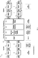
- FIG. 1 illustrates an embodiment of a network node 100 that may forward a plurality of timestamps in a network, e.g., using the Layer 2 timestamp-based scheme of IEEE 1588 for time synchronization and distribution.
- the network node 100 may be used in Ethernet networks to forward Ethernet packets 110, including timestamp references (e.g., timestamp packets).
- the network node 100 may be used in Time Domain Division (TDM) based networks, LANs, Passive Optical Networks (PONs), Digital Subscriber Line (DSL) systems, or any networks that use clocks/timing references to synchronize transmissions.
- TDM Time Domain Division
- PONs Passive Optical Networks
- DSL Digital Subscriber Line
- the network node 100 may comprise a plurality of physical layer (PHY) units 120 and MAC units 130 for each of a plurality of ingress ports and a plurality of egress ports, as shown in FIG. 1 .
- the ingress and egress ports may be coupled to other network nodes (not shown) in the network.
- the network node 100 may also comprise a connection admission control (CAC) block 140, a plurality of switching and forwarding tables 150, a plurality of output queues 160, and one or more output multiplexers (Mux) 170, all of which may be positioned between the ingress ports and the egress ports, for instance in a switch fabric 190.
- the units and blocks above may process the Ethernet packets 110 (including timestamp references or packets), e.g., at Layer 2, using hardware, software, or both.
- the PHY units 120 may be configured to receive the Ethernet packet 110, decapsulate/decode the packets at the PHY (Ethernet) layer, and send the packets at the MAC layer to the MAC units 130.
- the MAC units 130 may decapsulate/decode the packets at the MAC layer and obtain the timestamp references, also referred to herein interchangeably as timestamps.
- the packets may then be forwarded to the CAC block 140, which may be configured to identify the links or channels that correspond to the packets, e.g., using logical link identifiers (LLIDs) in the packets.
- LLIDs logical link identifiers
- the CAC block 140 may also be configured to identify the start of each frame or packet, e.g., using a start of frame delimiter (SFD) in the packet.
- the switching and forwarding tables 150 may be used to forward the packets based on their destination addresses and/or source addresses, implement address learning, and discard packets with unknown addresses.
- the output queues 160 may be used to queue or buffer the incoming packets before forwarding.
- the output multiplexer(s) 170 may be configured to multiplex incoming data into outgoing data blocks.
- the outgoing packets may then be processed by the MAC units 130 and then the PHY units 120 before being forwarded via the corresponding egress ports, e.g., to another network node.
- the MAC units 130 may encapsulate/encode the packets at the MAC layer and the PHY units 120 may then encapsulate/encode the packets at the PHY or Ethernet layer.
- the time references obtained from the Ethernet packets 110 may be processed to implement time synchronization and distribution, e.g., according to IEEE 1588.
- the path of the Ethernet packets (at Layer 2) in the network node 100 may be subject to a plurality of impairments that may affect the timing or alignment of the timestamps in the packets, and thus may affect the accuracy of the frequency/phase synchronization and distribution in the network.
- the timestamp impairments may be caused by possible PHY rate adaptation, e.g., at the PHY units 120.
- the PHY units 120 may add or remove typically un-used octets to make up for +/-100 parts per million (ppm), clock operation and/or other link delay variations.
- the timestamp impairments may also be caused by store-and-forward or cut-through operation selection, e.g., at the MAC units 130.
- the store-and-forward mode of operation for general packet traffic may contribute to packet delay variation (PDV) for timestamp packets due to the variable size of Ethernet packets.
- the store-and-forward or cut-through operation selection may require differential treatment of timestamp packets.
- the timestamp impairments may also be introduced when CAC parameters are set for general packet traffic, e.g., at the CAC block 140. Setting the CAC parameters may also require differential treatment of timestamp packets. Further, a non-blocking switching fabric and static forwarding of timestamp packets may be required for proper operation of timestamp-based synchronization, e.g., at the switching and forwarding tables 150. Otherwise, more timestamp impairments may be introduced. Traffic management issues may also contribute to the impairments. For instance, to optimize the performance of timestamp packets, differentiated traffic management rules may be required, e.g., at the output queues 160.
- Ethernet packets compliant with IEEE 802.3 standard may range from about 64 octets to about 2,000 octets in size. This range of packets may comprise actual packet sizes that may be in common use in the industry and comprise more than about 9,600 octets and Ethernet "idle" signaling units (SUs) that comprise about two octets.
- SUs Ethernet "idle" signaling units
- the various impairments above may be additive.
- the position or alignment of the timestamps may become less deterministic and affect the accuracy of the timestamp-based synchronization method.
- the undesired effects of such impairments may not be efficiently handled using current time synchronization and distribution schemes, such as based on IEEE 1588.
- the system and method may create and synchronize a periodic time window for the transmissions of timestamps in the outgoing direction of packet-mode participating links, e.g., on the egress of each of the participating nodes within a packet-mode network.
- the periodic time window may overcome expected timing errors due to the impairments above.
- a fixed assignment/scheduling may also be applied in the periodic time window for a plurality of timestamps designated for a plurality of network nodes, which may all be transmitted on the same link.
- the fixed assignment/scheduling may simplify the timing synchronization and distribution for multiple nodes in the network. Such system may improve timing synchronization and distribution in the network and may be used for frequency and/or phase clock adjustment. The implementation details and aspects are further described below.
- the system and method may be implemented for Ethernet packet-mode links and networks and may also be used in other networks and transport technologies, e.g., other statistically-multiplexed packet-mode networks.
- the timestamp impairments introduced by the network node components may cause misalignment of the timestamps in the transmitted packets between the network nodes.
- the network nodes may receive the timestamps out of order or at delays that may cause errors in the timing (frequency/phase) synchronization and distribution scheme.
- the network nodes may be configured to transmit a plurality of timestamps, e.g., for a plurality of designated network nodes on a link, periodically within a virtual periodic time window.
- the timestamps may be assigned a plurality of time slots or locations within the periodic time window, and the remaining portion of the periodic time window may be used to transmit other Ethernet packets.
- the timestamps may be sent within their assigned time slots in the periodic time window by buffering and then forwarding the timestamps appropriately.
- the length of the periodic time window may be determined to allow sufficient buffering time for the timestamps to prevent or substantially reduce any delays, misalignments, and/or contentions due to the impairments of the network node.
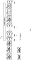
- FIG. 2 illustrates an embodiment of a periodic time window 200, which may be a virtual periodic time window used to control and regulate the transmission of the timestamps between the network nodes.
- the periodic time window 200 may comprise, at the start of the periodic time window 200, a plurality of timestamps or timing references 240 (e.g., TS 1, TS2, ..., TSn, where n is an integer) that may be separated by a plurality of idle symbols 215.
- the periodic time window 200 may also comprise other Ethernet traffic (e.g., packets) 210, a packet guard-band 220, and a PHY guard-band 230, which may succeed the timestamps 240 in that order (as shown in FIG. 2 ).
- the other Ethernet traffic 210 may also be separated from the timestamps 240 and the packet guard-band 220 by idle symbols 215.
- the periodic time window 200 may be virtual in the sense that the time slots 240, the other Ethernet traffic 210, the packet guard-band 220, and the PHY guard-band 230 may be transmitted in that order periodically, including the idle symbols 215.
- the transmission of the components of the periodic time window 200 may be repeated substantially periodically from the egress ports of the network nodes based on the determined length or time duration of the periodic time window 200.
- the start of the transmissions of the timestamps 240 may be determined by the length or time duration of the packet guard-band 220 and the PHY guard-band 230.
- the packet guard-band 220 may be a time pause where no transmissions may occur.
- the time duration of the packet guard-band 220 may be determined to be greater than or about equal to the largest Ethernet frame or packet transmission supported by the network, e.g., the largest allowed time to transmit one or a plurality of Ethernet packets continuously without interruption, including the minimum required inter-packet gap between packet transmissions.
- the minimum required inter-packet gap for Ethernet networks may be equal to about 12 octets.
- the PHY guard-band 230 may comprise one or more idle symbols that may have a longer time duration of the idle symbols 215.
- the time duration of the PHY guard-band 230 may be determined to be greater than or about equal to the sum of the minimum required inter-packet gap and at least one maximum possible expected PHY adjustment (e.g., by a PHY unit 120) that may occur.
- the maximum PHY adjustment may be dependent on the PHY scheme used in the network node, e.g., on the order of about four octets.
- each of the timestamps 240 may be allocated in a deterministic manner in the periodic time window 200 to a plurality of corresponding time slots.
- the time slots may be assigned to a plurality of network nodes on the same link in the network.
- a network node may transmit the timestamps 240 periodically, where each timestamp 240 may be designated according to its positioning in the periodic time window 200 to another corresponding network node on the link.
- the timestamps TS 1, TS2, ..., and TSn may be transmitted in that order in the periodic time window 200 and correspond to a plurality of network nodes that comprise a first node, a second node, ..., and an n-th node, in that same order on the link.
- the transmitted timestamps 240 may not be arranged in the same sequence of the corresponding nodes on the link if the network nodes are aware of the mapping between the time slots of the timestamp 240 in the periodic time window 200 and the corresponding designated nodes on the link.
- Each network node that has a designated timestamp 240 may receive the corresponding timestamp 240, use it in the timing synchronization and distribution scheme, and forward the remaining timestamps to the next network node on the link.
- the network node may also add a timestamp 240 in an allocated time slot in the periodic time window 200 and forward the added timestamp 240 with the remaining traffic to the next network node on the link.
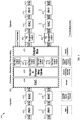
- FIG. 3 illustrates an embodiment of a network node 300 that may forward a plurality of timestamps in a network, e.g., at Layer 2.
- the network node 300 may also transmit a plurality of timestamps designated for a plurality of network nodes on a link in a periodic time window, e.g., the periodic time window 200.
- the network node 300 may be used in Ethernet networks to forward Ethernet packets 310, including timestamp references (e.g., timestamp packets).
- the network node 300 may be used in TDM based networks, LANs, PONs, DSL systems, or any networks that use clocks/timing references to synchronize transmissions.
- the network node 300 may comprise a plurality of PHY units 320 and MAC units 330 for each of a plurality of ingress ports and a plurality of egress ports, as shown in FIG. 3 .
- the ingress and egress ports may be coupled to other network nodes (not shown) in the network.
- the network node 300 may also comprise a CAC block 340, a plurality of switching and forwarding tables 350, a plurality of output queues 360, and one or more output multiplexers 370, all of which may be positioned between the ingress ports and the egress ports for instance in a switch fabric 390.
- the units and blocks above may process the Ethernet packets 310 (including timestamp references or packets), e.g., at Layer 2, using hardware, software, or both.
- the components above of the network node 300 may be configured substantially similar to the corresponding components of the network node 100.
- the network node 300 may comprise a plurality of timestamp (TS) support logic units 380 at the egress ports, between the MAC units 330 and the PHY units 320.
- the TS support logic units 380 may be used to buffer and transmit the timestamps and other Ethernet traffic in the periodic time window to compensate for possible impairments from the components of the network node 300.
- the TS support logic units 380 may compensate for possible impairments between the MAC units 330 and the PHY units 320.
- the TS support logic units 380 may also guarantee that the timestamps in the periodic time window are assigned to the corresponding time slots designated for the corresponding network nodes on the same link.
- the TS support logic 380 may be implemented using hardware, software, or both.
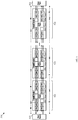
- FIG. 4 illustrates an embodiment of another network node 400 that may forward a plurality of timestamps in a network, e.g., at Layer 2.
- the network node 400 may also transmit a plurality of timestamps designated for a plurality of network nodes on a link in a periodic time window, e.g., the periodic time window 200.
- the network node 400 may be used in Ethernet networks, TDM based networks, LANs, PONs, DSL systems, or any networks that use clocks/timing references to synchronize transmissions.
- the network node 400 may comprise a plurality of PHY units 420 and MAC units 430 for each of a plurality of ingress ports and a plurality of egress ports, as shown in FIG. 4 .
- the ingress and egress ports may be coupled to other network nodes (not shown) in the network.
- the network node 400 may also comprise a CAC block 440, a plurality of switching and forwarding tables 450, a plurality of output queues 460, and one or more output multiplexers 470, all of which may be positioned between the ingress ports and the egress ports for instance in a switch fabric 490.
- the components of the network node 400 may process a plurality of Ethernet packets 410 (including timestamp references or packets), e.g., at Layer 2, using hardware, software, or both, and may be configured substantially similar to the corresponding components of the network node 100.
- the network node 400 may comprise a plurality of TS support logic units 480 at the egress ports, between the output multiplexer(s) 470 and the MAC units 430, which may be configured substantially similar to the TS support logic units 380.
- the TS support logic units 480 may compensate for possible impairments that may occur between the output multiplexer(s) 470 and the MAC units 430, and may be implemented using hardware, software, or both.
- FIG. 5 illustrates an embodiment of a timestamp forwarding scheme 500, which may use the periodic timestamp transmission scheme above, e.g., the periodic time window 200.
- the timestamp forwarding scheme 500 may be implemented using a plurality of network nodes 520, a clock source node 510, and a clock termination node 580.
- the network nodes 520 may comprise a plurality of network nodes 400, network nodes 500, and/or similarly configured network nodes.
- each of the network nodes 520 may comprise a plurality of components similar to the components of the network nodes 400 or 500, including a TS support logic unit (not shown) and a scheduler 522 coupled to the TS support logic unit.
- the TS support logic unit and the scheduler 522 may be both positioned between a switch fabric 590 and a MAC unit 530 at each egress port.
- the scheduler 522 may be positioned between the switch fabric 590 and the MAC unit 530, and the TS support logic unit may be positioned between the MAC unit 530 and a PHY unit 525.
- the switch fabric 590, the MAC unit 530, and the PHY unit 525 may be configured substantially similar to the switch fabric 190, the MAC unit 130, and the PHY unit 120, respectively.
- the TS support logic unit and the scheduler 522 may be both positioned between the MAC unit 530 and the PHY unit 525 at each egress port
- the clock source node 510 may be configured to generate and send a plurality of timestamps or time references, e.g., in Ethernet packets, in a forward direction to the clock termination node 530 via the network nodes 520.
- the timestamps may comprise an initial transmission time that may be synchronized with a master clock or absolute clock timing at the clock source node 510.
- Each of the network nodes 520 may use a corresponding timestamp in a periodic time window to adjust its clock timing.
- the timestamps may be received and processed by the clock termination node 530, where a reception or arrival time may be added in the timestamps before returning the timestamps back in a reverse direction to the clock source node 510.
- the clock source node 510 may then receive the returned timestamps and use the initial transmission time and the arrival time in the timestamps to calculate a roundtrip delay, which may then be used to adjust frequency and/or phase timing for the network nodes 520, the clock termination node 530, and possibly the clock source node 510.
- the offset delay may be about half the sum of a plurality forward offset delays between the nodes (e.g., F0, F1, ..., FN, where N is an integer) and a plurality of reverse offset delays (e.g., R0, R1, ..., RN).
- the clock source nodes 510 and/or the clock termination node 530 may be configured substantially similar to the network nodes 520. For instance, any two of the network nodes 520 may act as the clock source node 510 and the clock termination node 530.
- the scheduler 522 may be configured to guarantee that Ethernet packets that do not comprise timestamps are buffered in the network nodes 520 and temporarily kept from being forwarded to the egress port to ensure proper alignment of such Ethernet packets in the periodic time window.
- the scheduler 522 may receive the Ethernet packets that are not timestamp packets from the switch fabric 590, used to buffer or hold the Ethernet packets until the timestamps allocated to the periodic time window are sent out, and then send the Ethernet packets in the allocated time slot (e.g., as the other Ethernet traffic 210).
- the TS support logic unit at each of the network nodes 520 may be configured substantially similar to the TS support logic unit 380 or 480. Specifically, the TS support logic unit may identify and classify the timestamp packets on per flow (per link) basis and be used to buffer the timestamp packets until the packets may be sent in the corresponding assigned time slots per flow. Thus, the timestamp packets may be transmitted in a deterministic and periodic manner with no or substantially reduced (minimal) transmission link contention, where some contention with Ethernet idle SUs may still occur.
- This reduction in transmission link contention may be substantial in comparison to typical possible contentions, e.g., for a sum of about 2,000 Ethernet packets and about 12 idle SUs for IEEE 802.3 compliant Ethernet frames or a sum of about 9,600 Ethernet packets and about 12 idle SUs for standard Ethernet frame transmissions.
- Table 1 summarizes some of the improvements achieved using the periodic timestamp transmission scheme.
- the values in Table 1 show improvements for a plurality of Ethernet type networks, including 10 Megabit per second (Mbps) Ethernet (Eth-10), 100 Mbps or Fast Ethernet (FastE), one Gigabit per second (Gbps) Ethernet (GigE), and 10 Gbps Ethernet (10GE). The values show that, in all the included cases, the positioning of the timestamp packets may be improved by more than about 99 percent.
- Table 1 Improvements achieved using the periodic timestamp transmission scheme.
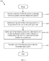
- FIG. 6 illustrates an embodiment of a periodic timestamp transmission method 600 that may be implemented by a network node, such as the network node 300, 400, or 520.
- the periodic timestamp transmission method 600 may be used to transmit a plurality of timestamps on a link periodically and assigned time slots corresponding to a plurality of nodes on the link.
- the method 600 may begin at block 610, where a plurality of Ethernet packets comprising timestamp packets and other data/control packets may be received.
- the Ethernet packets may comprise Ethernet data packets, other timestamp packets, and idle SUs.
- each of the timestamp packets may be identified and mapped to a designated network node on the same egress link.
- the timestamp packets may comprise destination addresses, node identifiers, and/or any other types of identities that may be used to identify the designated corresponding network nodes and the egress link.
- the timestamp packets may be aligned to a plurality of consecutive time slots that match in sequence the designated network nodes on the link.
- each of the Ethernet packets may be buffered for a determined time to align the Ethernet packets within a plurality of corresponding time slots in a virtual periodic time window for transmission, e.g., such as the periodic time window 200.
- the timestamp packets may be buffered, e.g., using the TS support logic unit 380 or 480, to align the timestamp packets at the start of the periodic time window preceding the other data/control packets.
- Each of the timestamp packets may be buffered to align the timestamp packets in corresponding time slots designated for network nodes designated to receive the corresponding timestamps on the same egress link.
- Each of the data/control packets may be buffered, e.g., using the scheduler 522, to align the data/control packets in a corresponding time slot subsequent to the time slots of the timestamp packets and preceding one or more guard-bands in the periodic time window to compensate for PHY, MAC, and/or other impairments in the network node that may cause packet contention.
- each of the buffered Ethernet packets may be transmitted after the determined time expires. The method 600 may then end.
- FIG. 7 illustrates an embodiment of a transmitter/receiver unit 700, which may be any device that transports packets through a network.
- the transmitter/receiver unit 700 may be located in any of the network components described above.
- the transmitted/receiver unit 700 may comprise one or more ingress ports or units 710 for receiving packets, objects, or Type Length Values (TLVs) from other network components, logic circuitry 720 to determine which network components to send the packets to, and one or more egress ports or units 730 for transmitting frames to the other network components.
- TLVs Type Length Values
- FIG. 8 illustrates a typical, general-purpose network component 800 suitable for implementing one or more embodiments of the components disclosed herein.
- the network component 800 includes a processor 802 (which may be referred to as a central processor unit or CPU) that is in communication with memory devices including secondary storage 804, read only memory (ROM) 806, random access memory (RAM) 808, input/output (I/O) devices 810, and network connectivity devices 812.
- the processor 802 may be implemented as one or more CPU chips, or may be part of one or more application specific integrated circuits (ASICs).
- ASICs application specific integrated circuits
- the secondary storage 804 is typically comprised of one or more disk drives or tape drives and is used for non-volatile storage of data and as an over-flow data storage device if RAM 808 is not large enough to hold all working data. Secondary storage 804 may be used to store programs that are loaded into RAM 808 when such programs are selected for execution.
- the ROM 806 is used to store instructions and perhaps data that are read during program execution. ROM 806 is a non-volatile memory device that typically has a small memory capacity relative to the larger memory capacity of secondary storage 804.
- the RAM 808 is used to store volatile data and perhaps to store instructions. Access to both ROM 806 and RAM 808 is typically faster than to second storage 804.
- R R l + k * (R u - R l ), wherein k is a variable ranging from 1 percent to 100 percent with a 1 percent increment, i.e., k is 1 percent, 2 percent, 3 percent, 4 percent, 5 percent, ..., 50 percent, 51 percent, 52 percent, ..., 95 percent, 96 percent, 97 percent, 98 percent, 99 percent, or 100 percent.
- any numerical range defined by two R numbers as defined in the above is also specifically disclosed.
Landscapes
- Engineering & Computer Science (AREA)
- Computer Networks & Wireless Communication (AREA)
- Signal Processing (AREA)
- Small-Scale Networks (AREA)
- Data Exchanges In Wide-Area Networks (AREA)
- Communication Control (AREA)
- Synchronisation In Digital Transmission Systems (AREA)
Claims (10)
- Appareil caractérisé par :un composant logique de support d'estampille temporelle (380, 480) configuré pour identifier une pluralité d'estampilles temporelles (240) pour une pluralité de noeuds de réseau sur une liaison unique et aligner les estampilles temporelles dans une pluralité d'intervalles de temps correspondants pour les noeuds de réseau sur la liaison unique à l'intérieur d'une fenêtre de temps de transmission périodique (200),l'estampille temporelle pour chaque noeud ayant une position unique pour son intervalle de temps correspondant à l'intérieur de la fenêtre de temps de transmission (200) ; etun planificateur (522) couplé au composant logique de support d'estampille temporelle (380, 480) et configuré pour aligner une pluralité de paquets qui ne comportent pas d'estampilles temporelles dans un intervalle de temps correspondant subséquent aux intervalles de temps pour les estampilles temporelles dans la fenêtre de temps de transmission périodique.
- Appareil selon la revendication 1, comprenant en outre :une unité de contrôle d'accès au support (MAC) (330, 430, 530) couplée au composant logique de support d'estampille temporelle (380, 480) ;une unité de couche physique (PHY) (320, 420, 525) couplée à l'unité MAC (330, 430, 530) ou au composant logique de support d'estampille temporelle (380, 480) ; et une matrice de commutation (390, 490) couplée au planificateur (522).
- Appareil selon la revendication 2, dans lequel le planificateur (522) et le composant logique de support d'estampille temporelle (380, 480) sont positionnés entre la matrice de commutation (390, 490) et l'unité MAC (330, 430, 530) ; ou
le planificateur (522) et le composant logique de support d'estampille temporelle (380, 480) sont positionnés entre l'unité MAC (330, 430, 530) et l'unité PHY (320, 420, 525). - Appareil selon la revendication 2, dans lequel le planificateur (522) est couplé au composant logique de support d'estampille temporelle (380, 480) par l'intermédiaire du l'unité MAC (330, 430, 530).
- Appareil selon la revendication 1, dans lequel la fenêtre de temps de transmission périodique (200) comprend les intervalles de temps pour les estampilles temporelles (240) au début de la fenêtre de temps de transmission périodique (200), l'intervalle de temps pour les paquets qui ne comportent pas d'estampilles temporelles, une bande de garde de paquet (220) pendant laquelle aucune transmission n'a lieu subséquemment à l'intervalle de temps des paquets qui ne comportent pas d'estampilles temporelles, et une bande de garde (230) de couche physique (PHY) qui comprend un ou plusieurs symboles inactifs subséquents à la bande de garde de paquet (220).
- Appareil selon la revendication 5, dans lequel la fenêtre de temps de transmission périodique (200) comprend en outre un symbole inactif (215) entre tous les deux intervalles de temps consécutifs pour les estampilles temporelles, un symbole inactif (215) entre les intervalles de temps pour les estampilles temporelles (240) et l'intervalle de temps pour les paquets qui ne comportent pas d'estampilles temporelles, et un symbole inactif (215) entre l'intervalle de temps pour les paquets qui ne comportent pas d'estampilles temporelles et la bande de garde de paquet (220).
- Procédé comprenant :recevoir une pluralité de paquets Ethernet comprenant des paquets d'estampille temporelle et d'autres paquets ;caractérisé par :identifier et mapper chacun des paquets d'estampille temporelle à un noeud de réseau désigné correspondant sur la même liaison de sortie ;mettre en mémoire tampon chacun des paquets Ethernet pendant un temps déterminé pour aligner les paquets Ethernet à l'intérieur d'une pluralité d'intervalles de temps correspondants dans une fenêtre de temps périodique virtuelle (200) pour une transmission ; ettransmettre chacun des paquets Ethernet après que le temps déterminé a expiré.
- Procédé selon la revendication 7, dans lequel les paquets d'estampille temporelle sont mappés à une pluralité de noeuds de réseau désignés correspondants en alignant les paquets d'estampille temporelle à une pluralité d'intervalles de temps consécutifs qui correspondent en séquence aux noeuds de réseau désignés sur la même liaison de sortie, ou les paquets d'estampille temporelle étant mappés à une pluralité de noeuds de réseau désignés correspondants en utilisant une pluralité d'identités correspondantes dans les paquets d'estampille temporelle pour identifier les noeuds de réseau désignés et la liaison de sortie.
- Procédé selon la revendication 7, dans lequel les paquets Ethernet sont mis en mémoire tampon pour permettre une bande de garde de paquet (220), pendant laquelle aucune transmission ne peut avoir lieu, et la bande de garde de paquet (220) ayant une durée de temps supérieure ou égale à une transmission de paquet Ethernet pris en charge par un plus grand réseau ou à une transmission de paquet comportant un intervalle inter-paquets minimum requis entre des transmissions de paquets.
- Procédé selon la revendication 9, dans lequel les paquets Ethernet sont en outre mis en mémoire tampon pour permettre une bande de garde (230) de couche physique (PHY) qui a une durée de temps supérieure ou égale à la somme de l'intervalle inter-paquets minimum requis et au moins un ajustement PHY attendu maximum possible.
Applications Claiming Priority (2)
| Application Number | Priority Date | Filing Date | Title |
|---|---|---|---|
| US36207410P | 2010-07-07 | 2010-07-07 | |
| PCT/US2011/043014 WO2012006311A1 (fr) | 2010-07-07 | 2011-07-06 | Placement déterministe de paquets à estampille temporelle utilisant une discontinuité périodique |
Publications (2)
| Publication Number | Publication Date |
|---|---|
| EP2586142A1 EP2586142A1 (fr) | 2013-05-01 |
| EP2586142B1 true EP2586142B1 (fr) | 2017-05-03 |
Family
ID=44629841
Family Applications (1)
| Application Number | Title | Priority Date | Filing Date |
|---|---|---|---|
| EP11741344.3A Not-in-force EP2586142B1 (fr) | 2010-07-07 | 2011-07-06 | Placement déterministe de paquets à estampille temporelle utilisant une discontinuité périodique |
Country Status (6)
| Country | Link |
|---|---|
| US (1) | US8842530B2 (fr) |
| EP (1) | EP2586142B1 (fr) |
| JP (1) | JP5395957B2 (fr) |
| CN (1) | CN102484548B (fr) |
| CA (1) | CA2760621C (fr) |
| WO (1) | WO2012006311A1 (fr) |
Families Citing this family (25)
| Publication number | Priority date | Publication date | Assignee | Title |
|---|---|---|---|---|
| KR20130127016A (ko) * | 2012-04-06 | 2013-11-22 | 한국전자통신연구원 | 멀티 스테이지 스위치에서의 패킷 플로우 제어 장치 및 방법 |
| CN104205852A (zh) * | 2012-04-13 | 2014-12-10 | 索尼公司 | 信息处理装置和方法以及程序 |
| EP3098995B1 (fr) * | 2014-03-10 | 2020-01-08 | Huawei Technologies Co., Ltd. | Procédé de transmission de données, dispositif émetteur et dispositif récepteur |
| CN109005019B (zh) * | 2014-12-31 | 2020-01-03 | 华为技术有限公司 | 信号发送和检测装置、系统及方法 |
| US9774458B2 (en) * | 2015-01-14 | 2017-09-26 | Alcatel-Lucent Usa Inc. | Method for transporting Ethernet and non-Ethernet traffic over the same medium |
| JP6607591B2 (ja) * | 2015-01-30 | 2019-11-20 | 日本電気株式会社 | 位相情報転送システム、位相情報送信装置、位相情報受信装置、および位相情報転送方法、ならびにプログラム |
| DE112015006136B4 (de) | 2015-03-19 | 2019-03-21 | Mitsubishi Electric Corporation | Kommunikationsvorrichtung und Netzwerksystem |
| CN104993919A (zh) * | 2015-07-02 | 2015-10-21 | 山东航天电子技术研究所 | 一种高效的自组网通信方法 |
| US9929928B1 (en) * | 2015-12-24 | 2018-03-27 | Microsemi Solutions (U.S.), Inc. | Packet transmitter and method for timestamping packets |
| EP3294014B1 (fr) * | 2016-09-08 | 2019-12-18 | ADVA Optical Networking SE | Procédé permettant de programmer une transmission de paquets dans un réseau |
| US11202268B2 (en) * | 2018-05-25 | 2021-12-14 | Solid, Inc. | Distributed antenna system and method of operation thereof |
| EP3591929A1 (fr) * | 2018-07-06 | 2020-01-08 | Nokia Solutions and Networks Oy | Garantie de fonctionnement d'un réseau de communication dans le cas d'un état anormal de la circulation |
| EP4082295B1 (fr) | 2020-01-21 | 2024-07-03 | Zeku Technology (Shanghai) Corp., Ltd. | Alignement et décodage de protocole de liaison descendante |
| EP4097984A4 (fr) * | 2020-01-30 | 2023-08-02 | ARRIS Enterprises LLC | Procédé et appareil de re-établissement de priorité de paquet vidéo wi-fi pour une diffusion en continu de transport mpeg en direct |
| CN113271653B (zh) | 2020-02-14 | 2022-06-10 | 华为技术有限公司 | 通信方法、装置及系统 |
| US10992419B1 (en) * | 2020-03-12 | 2021-04-27 | Nxp B.V. | Wireless communications device and method for performing an angle measurement |
| CN112419698B (zh) * | 2020-10-26 | 2022-05-17 | 浙江正泰仪器仪表有限责任公司 | 基于配电线报文规范的电能表数据传输方法、系统及装置 |
| CN112511283B (zh) * | 2020-11-12 | 2022-05-31 | 鹏城实验室 | 一种时间敏感网络的循环周期时隙计数方法及电子设备 |
| CN116615882B (zh) * | 2020-12-24 | 2024-06-21 | 高通股份有限公司 | 确定用于非周期性探通参考信号(srs)资源集的可用时隙 |
| CN113708903B (zh) * | 2021-07-09 | 2022-12-02 | 北京邮电大学 | 基于时间戳的信令确定性传输方法、装置、设备及介质 |
| US20240396656A1 (en) * | 2021-09-27 | 2024-11-28 | Telefonaktiebolaget Lm Ericsson (Publ) | Protocol for increased accuracy time stamping interworking on high speed ethernet links |
| CN116686324A (zh) * | 2021-12-29 | 2023-09-01 | 新华三技术有限公司 | 应用于确定性网中的csqf调度周期收集方法及装置 |
| US12199770B1 (en) * | 2022-07-29 | 2025-01-14 | Cadence Design Systems, Inc. | High accuracy timestamping of transmissions at physical layer of communication devices and systems |
| CN115460039B (zh) * | 2022-08-17 | 2023-07-11 | 珠海高凌信息科技股份有限公司 | 基于逻辑网络的大容量tdm交换系统和方法、存储介质 |
| CN115967922B (zh) * | 2023-03-16 | 2023-06-16 | 中铁第四勘察设计院集团有限公司 | 一种双制式网络的车地无线通信系统及方法 |
Family Cites Families (12)
| Publication number | Priority date | Publication date | Assignee | Title |
|---|---|---|---|---|
| EP0895378B1 (fr) * | 1996-05-07 | 2006-03-08 | Yamaha Corporation | Procédé et système de transmission de données audio avec signal d'horodatage |
| US6404770B1 (en) * | 1997-12-02 | 2002-06-11 | Yamaha Corporation | Data communication interface with adjustable-size buffer |
| US6247058B1 (en) | 1998-03-30 | 2001-06-12 | Hewlett-Packard Company | Method and apparatus for processing network packets using time stamps |
| US6272131B1 (en) * | 1998-06-11 | 2001-08-07 | Synchrodyne Networks, Inc. | Integrated data packet network using a common time reference |
| US6654345B1 (en) | 1998-11-05 | 2003-11-25 | Agere Systems Inc. | Single-bit timestamps for data transfer rate and delay guarantees in a packet network |
| US7486693B2 (en) * | 2001-12-14 | 2009-02-03 | General Electric Company | Time slot protocol |
| ATE418819T1 (de) | 2004-08-25 | 2009-01-15 | Nokia Siemens Networks Gmbh | Verfahren und system zur taktuhrenaktualisierung in komponenten eines kommunikationsnetzwerks |
| DE102005004464A1 (de) | 2005-01-31 | 2006-10-26 | Robert Bosch Gmbh | Verfahren zur Speicherung von Botschaften in einem Botschaftsspeicher und Botschaftsspeicher |
| US20080075019A1 (en) * | 2006-09-27 | 2008-03-27 | Petras Charles E | Data Mapping and Sorting Method in Network Communication |
| US7787486B2 (en) | 2006-11-13 | 2010-08-31 | Honeywell International Inc. | Method and system for achieving low jitter in real-time switched networks |
| US20080139212A1 (en) | 2006-12-07 | 2008-06-12 | Motorola, Inc. | Apparatus and method for interoperation of various radio links with a piconet link in a wireless device |
| CN101527687A (zh) | 2008-04-03 | 2009-09-09 | 中国人民解放军国防科学技术大学 | 基于时间压力的时间确定性数据交换装置 |
-
2011
- 2011-07-06 EP EP11741344.3A patent/EP2586142B1/fr not_active Not-in-force
- 2011-07-06 CA CA2760621A patent/CA2760621C/fr active Active
- 2011-07-06 WO PCT/US2011/043014 patent/WO2012006311A1/fr not_active Ceased
- 2011-07-06 CN CN201180001695.XA patent/CN102484548B/zh not_active Expired - Fee Related
- 2011-07-06 US US13/176,805 patent/US8842530B2/en active Active
- 2011-07-06 JP JP2012524002A patent/JP5395957B2/ja not_active Expired - Fee Related
Non-Patent Citations (1)
| Title |
|---|
| None * |
Also Published As
| Publication number | Publication date |
|---|---|
| CA2760621A1 (fr) | 2012-01-07 |
| EP2586142A1 (fr) | 2013-05-01 |
| CN102484548B (zh) | 2015-05-13 |
| WO2012006311A1 (fr) | 2012-01-12 |
| US8842530B2 (en) | 2014-09-23 |
| JP5395957B2 (ja) | 2014-01-22 |
| CA2760621C (fr) | 2016-11-01 |
| JP2012533266A (ja) | 2012-12-20 |
| US20120008646A1 (en) | 2012-01-12 |
| CN102484548A (zh) | 2012-05-30 |
Similar Documents
| Publication | Publication Date | Title |
|---|---|---|
| EP2586142B1 (fr) | Placement déterministe de paquets à estampille temporelle utilisant une discontinuité périodique | |
| US8571068B2 (en) | Network timing distribution and synchronization using virtual network delays | |
| EP3319251B1 (fr) | Appareil et procédé de transmission de paquets avec retard contrôlé | |
| CN101517944B (zh) | 向通信装置提供分组的方法、同步分组分配的方法和系统 | |
| CN101584164B (zh) | 闭环时钟同步 | |
| EP2382743B1 (fr) | Appareil et procédé permettant d'ordonnancer des paquets de synchronisation afin d'améliorer la distribution temporelle dans des réseaux de télécommunication | |
| WO2012003746A1 (fr) | Procédé et dispositif de réalisation d'horloge frontière | |
| EP3278518B1 (fr) | Noeud de réseau | |
| US8547864B2 (en) | Layer one path delay compensation | |
| CN110870285A (zh) | 在具有部分实时需求的数据网络中高性能数据传输的方法和执行该方法的装置 | |
| US20120099432A1 (en) | Decreasing jitter in packetized communication systems | |
| US10361962B2 (en) | Packet processing technique for a communication network | |
| Zou et al. | Options for time-sensitive networking for 5G fronthaul | |
| Schumacher et al. | Node to node synchronization accuracy requirements of dynamic frame packing | |
| CN102811168B (zh) | 同步网络交换机 | |
| Freire et al. | Analysis of controlled packet departure to support Ethernet fronthaul synchronization via PTP |
Legal Events
| Date | Code | Title | Description |
|---|---|---|---|
| PUAI | Public reference made under article 153(3) epc to a published international application that has entered the european phase |
Free format text: ORIGINAL CODE: 0009012 |
|
| 17P | Request for examination filed |
Effective date: 20111216 |
|
| AK | Designated contracting states |
Kind code of ref document: A1 Designated state(s): AL AT BE BG CH CY CZ DE DK EE ES FI FR GB GR HR HU IE IS IT LI LT LU LV MC MK MT NL NO PL PT RO RS SE SI SK SM TR |
|
| R17P | Request for examination filed (corrected) |
Effective date: 20111216 |
|
| 17Q | First examination report despatched |
Effective date: 20130703 |
|
| DAX | Request for extension of the european patent (deleted) | ||
| GRAP | Despatch of communication of intention to grant a patent |
Free format text: ORIGINAL CODE: EPIDOSNIGR1 |
|
| RIC1 | Information provided on ipc code assigned before grant |
Ipc: H04L 12/54 20060101ALI20161010BHEP Ipc: H04J 3/06 20060101AFI20161010BHEP |
|
| INTG | Intention to grant announced |
Effective date: 20161027 |
|
| GRAS | Grant fee paid |
Free format text: ORIGINAL CODE: EPIDOSNIGR3 |
|
| STAA | Information on the status of an ep patent application or granted ep patent |
Free format text: STATUS: GRANT OF PATENT IS INTENDED |
|
| GRAJ | Information related to disapproval of communication of intention to grant by the applicant or resumption of examination proceedings by the epo deleted |
Free format text: ORIGINAL CODE: EPIDOSDIGR1 |
|
| GRAL | Information related to payment of fee for publishing/printing deleted |
Free format text: ORIGINAL CODE: EPIDOSDIGR3 |
|
| STAA | Information on the status of an ep patent application or granted ep patent |
Free format text: STATUS: EXAMINATION IS IN PROGRESS |
|
| GRAR | Information related to intention to grant a patent recorded |
Free format text: ORIGINAL CODE: EPIDOSNIGR71 |
|
| STAA | Information on the status of an ep patent application or granted ep patent |
Free format text: STATUS: GRANT OF PATENT IS INTENDED |
|
| GRAA | (expected) grant |
Free format text: ORIGINAL CODE: 0009210 |
|
| STAA | Information on the status of an ep patent application or granted ep patent |
Free format text: STATUS: THE PATENT HAS BEEN GRANTED |
|
| INTC | Intention to grant announced (deleted) | ||
| AK | Designated contracting states |
Kind code of ref document: B1 Designated state(s): AL AT BE BG CH CY CZ DE DK EE ES FI FR GB GR HR HU IE IS IT LI LT LU LV MC MK MT NL NO PL PT RO RS SE SI SK SM TR |
|
| INTG | Intention to grant announced |
Effective date: 20170324 |
|
| REG | Reference to a national code |
Ref country code: GB Ref legal event code: FG4D |
|
| REG | Reference to a national code |
Ref country code: AT Ref legal event code: REF Ref document number: 891078 Country of ref document: AT Kind code of ref document: T Effective date: 20170515 Ref country code: CH Ref legal event code: EP |
|
| REG | Reference to a national code |
Ref country code: IE Ref legal event code: FG4D |
|
| REG | Reference to a national code |
Ref country code: FR Ref legal event code: PLFP Year of fee payment: 7 |
|
| REG | Reference to a national code |
Ref country code: DE Ref legal event code: R096 Ref document number: 602011037573 Country of ref document: DE |
|
| REG | Reference to a national code |
Ref country code: NL Ref legal event code: MP Effective date: 20170503 |
|
| REG | Reference to a national code |
Ref country code: AT Ref legal event code: MK05 Ref document number: 891078 Country of ref document: AT Kind code of ref document: T Effective date: 20170503 |
|
| REG | Reference to a national code |
Ref country code: LT Ref legal event code: MG4D |
|
| PG25 | Lapsed in a contracting state [announced via postgrant information from national office to epo] |
Ref country code: LT Free format text: LAPSE BECAUSE OF FAILURE TO SUBMIT A TRANSLATION OF THE DESCRIPTION OR TO PAY THE FEE WITHIN THE PRESCRIBED TIME-LIMIT Effective date: 20170503 Ref country code: HR Free format text: LAPSE BECAUSE OF FAILURE TO SUBMIT A TRANSLATION OF THE DESCRIPTION OR TO PAY THE FEE WITHIN THE PRESCRIBED TIME-LIMIT Effective date: 20170503 Ref country code: GR Free format text: LAPSE BECAUSE OF FAILURE TO SUBMIT A TRANSLATION OF THE DESCRIPTION OR TO PAY THE FEE WITHIN THE PRESCRIBED TIME-LIMIT Effective date: 20170804 Ref country code: FI Free format text: LAPSE BECAUSE OF FAILURE TO SUBMIT A TRANSLATION OF THE DESCRIPTION OR TO PAY THE FEE WITHIN THE PRESCRIBED TIME-LIMIT Effective date: 20170503 Ref country code: ES Free format text: LAPSE BECAUSE OF FAILURE TO SUBMIT A TRANSLATION OF THE DESCRIPTION OR TO PAY THE FEE WITHIN THE PRESCRIBED TIME-LIMIT Effective date: 20170503 Ref country code: AT Free format text: LAPSE BECAUSE OF FAILURE TO SUBMIT A TRANSLATION OF THE DESCRIPTION OR TO PAY THE FEE WITHIN THE PRESCRIBED TIME-LIMIT Effective date: 20170503 Ref country code: NO Free format text: LAPSE BECAUSE OF FAILURE TO SUBMIT A TRANSLATION OF THE DESCRIPTION OR TO PAY THE FEE WITHIN THE PRESCRIBED TIME-LIMIT Effective date: 20170803 |
|
| PG25 | Lapsed in a contracting state [announced via postgrant information from national office to epo] |
Ref country code: IS Free format text: LAPSE BECAUSE OF FAILURE TO SUBMIT A TRANSLATION OF THE DESCRIPTION OR TO PAY THE FEE WITHIN THE PRESCRIBED TIME-LIMIT Effective date: 20170903 Ref country code: RS Free format text: LAPSE BECAUSE OF FAILURE TO SUBMIT A TRANSLATION OF THE DESCRIPTION OR TO PAY THE FEE WITHIN THE PRESCRIBED TIME-LIMIT Effective date: 20170503 Ref country code: SE Free format text: LAPSE BECAUSE OF FAILURE TO SUBMIT A TRANSLATION OF THE DESCRIPTION OR TO PAY THE FEE WITHIN THE PRESCRIBED TIME-LIMIT Effective date: 20170503 Ref country code: BG Free format text: LAPSE BECAUSE OF FAILURE TO SUBMIT A TRANSLATION OF THE DESCRIPTION OR TO PAY THE FEE WITHIN THE PRESCRIBED TIME-LIMIT Effective date: 20170803 Ref country code: NL Free format text: LAPSE BECAUSE OF FAILURE TO SUBMIT A TRANSLATION OF THE DESCRIPTION OR TO PAY THE FEE WITHIN THE PRESCRIBED TIME-LIMIT Effective date: 20170503 Ref country code: LV Free format text: LAPSE BECAUSE OF FAILURE TO SUBMIT A TRANSLATION OF THE DESCRIPTION OR TO PAY THE FEE WITHIN THE PRESCRIBED TIME-LIMIT Effective date: 20170503 Ref country code: PL Free format text: LAPSE BECAUSE OF FAILURE TO SUBMIT A TRANSLATION OF THE DESCRIPTION OR TO PAY THE FEE WITHIN THE PRESCRIBED TIME-LIMIT Effective date: 20170503 |
|
| PG25 | Lapsed in a contracting state [announced via postgrant information from national office to epo] |
Ref country code: CZ Free format text: LAPSE BECAUSE OF FAILURE TO SUBMIT A TRANSLATION OF THE DESCRIPTION OR TO PAY THE FEE WITHIN THE PRESCRIBED TIME-LIMIT Effective date: 20170503 Ref country code: RO Free format text: LAPSE BECAUSE OF FAILURE TO SUBMIT A TRANSLATION OF THE DESCRIPTION OR TO PAY THE FEE WITHIN THE PRESCRIBED TIME-LIMIT Effective date: 20170503 Ref country code: DK Free format text: LAPSE BECAUSE OF FAILURE TO SUBMIT A TRANSLATION OF THE DESCRIPTION OR TO PAY THE FEE WITHIN THE PRESCRIBED TIME-LIMIT Effective date: 20170503 Ref country code: SK Free format text: LAPSE BECAUSE OF FAILURE TO SUBMIT A TRANSLATION OF THE DESCRIPTION OR TO PAY THE FEE WITHIN THE PRESCRIBED TIME-LIMIT Effective date: 20170503 Ref country code: EE Free format text: LAPSE BECAUSE OF FAILURE TO SUBMIT A TRANSLATION OF THE DESCRIPTION OR TO PAY THE FEE WITHIN THE PRESCRIBED TIME-LIMIT Effective date: 20170503 |
|
| REG | Reference to a national code |
Ref country code: DE Ref legal event code: R097 Ref document number: 602011037573 Country of ref document: DE |
|
| PG25 | Lapsed in a contracting state [announced via postgrant information from national office to epo] |
Ref country code: IT Free format text: LAPSE BECAUSE OF FAILURE TO SUBMIT A TRANSLATION OF THE DESCRIPTION OR TO PAY THE FEE WITHIN THE PRESCRIBED TIME-LIMIT Effective date: 20170503 Ref country code: SM Free format text: LAPSE BECAUSE OF FAILURE TO SUBMIT A TRANSLATION OF THE DESCRIPTION OR TO PAY THE FEE WITHIN THE PRESCRIBED TIME-LIMIT Effective date: 20170503 |
|
| REG | Reference to a national code |
Ref country code: CH Ref legal event code: PL |
|
| PLBE | No opposition filed within time limit |
Free format text: ORIGINAL CODE: 0009261 |
|
| STAA | Information on the status of an ep patent application or granted ep patent |
Free format text: STATUS: NO OPPOSITION FILED WITHIN TIME LIMIT |
|
| 26N | No opposition filed |
Effective date: 20180206 |
|
| REG | Reference to a national code |
Ref country code: IE Ref legal event code: MM4A |
|
| PG25 | Lapsed in a contracting state [announced via postgrant information from national office to epo] |
Ref country code: IE Free format text: LAPSE BECAUSE OF NON-PAYMENT OF DUE FEES Effective date: 20170706 Ref country code: LI Free format text: LAPSE BECAUSE OF NON-PAYMENT OF DUE FEES Effective date: 20170731 Ref country code: CH Free format text: LAPSE BECAUSE OF NON-PAYMENT OF DUE FEES Effective date: 20170731 |
|
| PG25 | Lapsed in a contracting state [announced via postgrant information from national office to epo] |
Ref country code: SI Free format text: LAPSE BECAUSE OF FAILURE TO SUBMIT A TRANSLATION OF THE DESCRIPTION OR TO PAY THE FEE WITHIN THE PRESCRIBED TIME-LIMIT Effective date: 20170503 |
|
| REG | Reference to a national code |
Ref country code: BE Ref legal event code: MM Effective date: 20170731 |
|
| REG | Reference to a national code |
Ref country code: FR Ref legal event code: PLFP Year of fee payment: 8 |
|
| PG25 | Lapsed in a contracting state [announced via postgrant information from national office to epo] |
Ref country code: LU Free format text: LAPSE BECAUSE OF NON-PAYMENT OF DUE FEES Effective date: 20170706 |
|
| PG25 | Lapsed in a contracting state [announced via postgrant information from national office to epo] |
Ref country code: BE Free format text: LAPSE BECAUSE OF NON-PAYMENT OF DUE FEES Effective date: 20170731 |
|
| PG25 | Lapsed in a contracting state [announced via postgrant information from national office to epo] |
Ref country code: MT Free format text: LAPSE BECAUSE OF NON-PAYMENT OF DUE FEES Effective date: 20170706 |
|
| PG25 | Lapsed in a contracting state [announced via postgrant information from national office to epo] |
Ref country code: HU Free format text: LAPSE BECAUSE OF FAILURE TO SUBMIT A TRANSLATION OF THE DESCRIPTION OR TO PAY THE FEE WITHIN THE PRESCRIBED TIME-LIMIT; INVALID AB INITIO Effective date: 20110706 Ref country code: MC Free format text: LAPSE BECAUSE OF FAILURE TO SUBMIT A TRANSLATION OF THE DESCRIPTION OR TO PAY THE FEE WITHIN THE PRESCRIBED TIME-LIMIT Effective date: 20170503 |
|
| PG25 | Lapsed in a contracting state [announced via postgrant information from national office to epo] |
Ref country code: CY Free format text: LAPSE BECAUSE OF NON-PAYMENT OF DUE FEES Effective date: 20170503 |
|
| PG25 | Lapsed in a contracting state [announced via postgrant information from national office to epo] |
Ref country code: MK Free format text: LAPSE BECAUSE OF FAILURE TO SUBMIT A TRANSLATION OF THE DESCRIPTION OR TO PAY THE FEE WITHIN THE PRESCRIBED TIME-LIMIT Effective date: 20170503 |
|
| PG25 | Lapsed in a contracting state [announced via postgrant information from national office to epo] |
Ref country code: TR Free format text: LAPSE BECAUSE OF FAILURE TO SUBMIT A TRANSLATION OF THE DESCRIPTION OR TO PAY THE FEE WITHIN THE PRESCRIBED TIME-LIMIT Effective date: 20170503 |
|
| PG25 | Lapsed in a contracting state [announced via postgrant information from national office to epo] |
Ref country code: PT Free format text: LAPSE BECAUSE OF FAILURE TO SUBMIT A TRANSLATION OF THE DESCRIPTION OR TO PAY THE FEE WITHIN THE PRESCRIBED TIME-LIMIT Effective date: 20170503 |
|
| PG25 | Lapsed in a contracting state [announced via postgrant information from national office to epo] |
Ref country code: AL Free format text: LAPSE BECAUSE OF FAILURE TO SUBMIT A TRANSLATION OF THE DESCRIPTION OR TO PAY THE FEE WITHIN THE PRESCRIBED TIME-LIMIT Effective date: 20170503 |
|
| PGFP | Annual fee paid to national office [announced via postgrant information from national office to epo] |
Ref country code: GB Payment date: 20220606 Year of fee payment: 12 |
|
| PGFP | Annual fee paid to national office [announced via postgrant information from national office to epo] |
Ref country code: FR Payment date: 20220609 Year of fee payment: 12 |
|
| PGFP | Annual fee paid to national office [announced via postgrant information from national office to epo] |
Ref country code: DE Payment date: 20220531 Year of fee payment: 12 |
|
| REG | Reference to a national code |
Ref country code: DE Ref legal event code: R119 Ref document number: 602011037573 Country of ref document: DE |
|
| GBPC | Gb: european patent ceased through non-payment of renewal fee |
Effective date: 20230706 |
|
| PG25 | Lapsed in a contracting state [announced via postgrant information from national office to epo] |
Ref country code: DE Free format text: LAPSE BECAUSE OF NON-PAYMENT OF DUE FEES Effective date: 20240201 Ref country code: GB Free format text: LAPSE BECAUSE OF NON-PAYMENT OF DUE FEES Effective date: 20230706 |
|
| PG25 | Lapsed in a contracting state [announced via postgrant information from national office to epo] |
Ref country code: FR Free format text: LAPSE BECAUSE OF NON-PAYMENT OF DUE FEES Effective date: 20230731 |