EP3294014B1 - Procédé permettant de programmer une transmission de paquets dans un réseau - Google Patents
Procédé permettant de programmer une transmission de paquets dans un réseau Download PDFInfo
- Publication number
- EP3294014B1 EP3294014B1 EP16187925.9A EP16187925A EP3294014B1 EP 3294014 B1 EP3294014 B1 EP 3294014B1 EP 16187925 A EP16187925 A EP 16187925A EP 3294014 B1 EP3294014 B1 EP 3294014B1
- Authority
- EP
- European Patent Office
- Prior art keywords
- network
- synchronization
- packets
- node
- section
- Prior art date
- Legal status (The legal status is an assumption and is not a legal conclusion. Google has not performed a legal analysis and makes no representation as to the accuracy of the status listed.)
- Active
Links
Images




Classifications
-
- H—ELECTRICITY
- H04—ELECTRIC COMMUNICATION TECHNIQUE
- H04W—WIRELESS COMMUNICATION NETWORKS
- H04W72/00—Local resource management
- H04W72/50—Allocation or scheduling criteria for wireless resources
- H04W72/52—Allocation or scheduling criteria for wireless resources based on load
-
- H—ELECTRICITY
- H04—ELECTRIC COMMUNICATION TECHNIQUE
- H04L—TRANSMISSION OF DIGITAL INFORMATION, e.g. TELEGRAPHIC COMMUNICATION
- H04L7/00—Arrangements for synchronising receiver with transmitter
- H04L7/0016—Arrangements for synchronising receiver with transmitter correction of synchronization errors
- H04L7/0033—Correction by delay
-
- H—ELECTRICITY
- H04—ELECTRIC COMMUNICATION TECHNIQUE
- H04W—WIRELESS COMMUNICATION NETWORKS
- H04W28/00—Network traffic management; Network resource management
- H04W28/02—Traffic management, e.g. flow control or congestion control
- H04W28/0289—Congestion control
-
- H—ELECTRICITY
- H04—ELECTRIC COMMUNICATION TECHNIQUE
- H04W—WIRELESS COMMUNICATION NETWORKS
- H04W56/00—Synchronisation arrangements
- H04W56/001—Synchronization between nodes
-
- H—ELECTRICITY
- H04—ELECTRIC COMMUNICATION TECHNIQUE
- H04W—WIRELESS COMMUNICATION NETWORKS
- H04W72/00—Local resource management
- H04W72/20—Control channels or signalling for resource management
-
- H—ELECTRICITY
- H04—ELECTRIC COMMUNICATION TECHNIQUE
- H04W—WIRELESS COMMUNICATION NETWORKS
- H04W8/00—Network data management
- H04W8/02—Processing of mobility data, e.g. registration information at HLR [Home Location Register] or VLR [Visitor Location Register]; Transfer of mobility data, e.g. between HLR, VLR or external networks
- H04W8/04—Registration at HLR or HSS [Home Subscriber Server]
-
- H—ELECTRICITY
- H04—ELECTRIC COMMUNICATION TECHNIQUE
- H04L—TRANSMISSION OF DIGITAL INFORMATION, e.g. TELEGRAPHIC COMMUNICATION
- H04L69/00—Network arrangements, protocols or services independent of the application payload and not provided for in the other groups of this subclass
- H04L69/30—Definitions, standards or architectural aspects of layered protocol stacks
- H04L69/32—Architecture of open systems interconnection [OSI] 7-layer type protocol stacks, e.g. the interfaces between the data link level and the physical level
- H04L69/322—Intralayer communication protocols among peer entities or protocol data unit [PDU] definitions
- H04L69/323—Intralayer communication protocols among peer entities or protocol data unit [PDU] definitions in the physical layer [OSI layer 1]
-
- H—ELECTRICITY
- H04—ELECTRIC COMMUNICATION TECHNIQUE
- H04L—TRANSMISSION OF DIGITAL INFORMATION, e.g. TELEGRAPHIC COMMUNICATION
- H04L69/00—Network arrangements, protocols or services independent of the application payload and not provided for in the other groups of this subclass
- H04L69/30—Definitions, standards or architectural aspects of layered protocol stacks
- H04L69/32—Architecture of open systems interconnection [OSI] 7-layer type protocol stacks, e.g. the interfaces between the data link level and the physical level
- H04L69/322—Intralayer communication protocols among peer entities or protocol data unit [PDU] definitions
- H04L69/324—Intralayer communication protocols among peer entities or protocol data unit [PDU] definitions in the data link layer [OSI layer 2], e.g. HDLC
-
- H—ELECTRICITY
- H04—ELECTRIC COMMUNICATION TECHNIQUE
- H04W—WIRELESS COMMUNICATION NETWORKS
- H04W88/00—Devices specially adapted for wireless communication networks, e.g. terminals, base stations or access point devices
- H04W88/08—Access point devices
- H04W88/085—Access point devices with remote components
Definitions
- a possible approach is to use boundary clocks to mitigate a packet delay variation caused by other interfering synchronization packets by partitioning a large network into network segments.
- Using transparent clocks mitigates variation induced by the residence time of a synchronization packet within a network bridge device by performing additional input and output timestamping.
- This conventional mechanism is also known as delay equalization.
- a disadvantage of the packet-based synchronization approaches like IEEE 1588 is that they are sensitive to packet delay variation and packet delay asymmetry caused by congestion or other reasons. For instance, the achievable precision for IEEE 1588v2 phase and time alignment is usually below 1 ⁇ s, if transparent clock mechanisms are applied. For instance, with Cisco Nexus 3000 switches a phase and time alignment below 500 ns can be reached. Further, IEEE 802.1AS can achieve an accuracy for phase and time synchronization below 500 ns.
- An advantage of the present invention is that the synchronization packets do not suffer any congestions since the specific time slots are reserved and allocated for the synchronization packets. Since there is no congestion this avoids any packet delay variation caused by queueing within the network.
- the congestion protected section of the common periodic time window further comprises a congestion protected data section partitioned into time slots dedicated to other packets being less sensitive or insensitive to delay variation.
- these other packets comprise data packets and/or control packets.
- the common periodic time window comprises the congestion protected section, an unpartitioned best effort section and an unpartitioned best effort guard section.
- This embodiment combines the advantage of having a zero congestion and packet delay for synchronization packets with the increased efficiency of using priority-based packet transmission.
- the unpartitioned best effort guard section comprises a physical layer and/or a link layer guard section having a size corresponding to a fragment size of a data fragment of packets transmitted in the unpartitioned best effort section.
- a latency introduced by the used common periodic time window is deterministic and is automatically compensated to minimize a delay variation within the network.
- the synchronization packet transmitted by a node of the network carries a time stamp generated by a time stamp generation unit of the respective node.
- the duration of the common periodic time window and/or the duration of the time slots is preconfigured.
- the duration of the common periodic time window and/or the duration of the time slot is adjusted adaptively during operation of the network.
- the network comprises at least one network segment having a time master node and at least one slave node.
- the time master node of the network segment transmits unidirectionally synchronization packets to a slave node of the network segment during a downlink time slot of a congestion protected synchronization section of the common periodic time window dedicated to the synchronization of the respective slave node and the slave node of the network segment in turn transmits unidirectionally synchronization packets to the time master node of said network segment during uplink time slots of the congestion protected synchronization section of the common periodic time window dedicated to the synchronization of the respective slave node.
- a slave node of a network segment of the network transmits unidirectionally data packets and/or control packets to another slave node of the same network segment of the network during a first time slot of the congestion protected data section of the common periodic time window dedicated to a bidirectional communication channel between both slave nodes of the network segment and wherein the other slave node of the network segment transmits unidirectionally data packets and/or control packets to the respective slave node during a second time slot of the congestion protected data section of the common periodic time window dedicated to the bidirectional communication channel between both slave nodes of said network segment of the network.
- packets exchanged between slave nodes of a network segment of the network are transmitted hop to hop via signal lines and network switches of the network, wherein an additional latency introduced by the signal lines and the network switches is minimized by shifting the time slots dedicated to the respective packets within the common periodic time window from hop to hop to compensate the additional latency.
- a start-up phase is provided as described above but the second step of the start-up phase is omitted.
- the second step of the start-up phase may be divided or partitioned into sub-steps whereby the length of the time-slot guard section is decreased from sub-step to sub-step in dependency on the synchronization accuracy.
- the invention further provides according to a further aspect a network comprising nodes each being adapted to perform a scheduling method according to the first aspect of the present invention.
- the network comprises an access network.
- the network comprises a fronthaul network.
- the network comprises a midhaul network.
- the network comprises a backhaul network.
- the network comprises a 5G mobile communication network.
- the network is a time-triggered network comprising one or several network segments each comprising a time master node and slave nodes synchronized to each other by a packet-based synchronization mechanism.
- the slave node of the network segment comprises a radio remote head, RRH.
- the slave nodes of the network segment comprise baseband units, BBU.
- the invention further provides according to a further aspect a node of a network, said node comprising ports each adapted to perform a scheduling method according to the first aspect of the present invention.
- a network 1 where the scheduling method according to the first aspect of the present invention can be employed can comprise several network nodes.
- Fig. 1 shows the topology of a small exemplary network 1 where a scheduling method according to the first aspect of the present invention can be used.
- the network comprises a single network segment comprising a master node 2 which can be formed by a time master node responsible for the timing within the single network segment of the packet switch network 1.
- the network 1 can comprise several network segments each having an associated master node 2.
- the master node 2 is adapted to provide synchronization of the nodes within the respective network segment of the network 1.
- the network 1 further comprises in the illustrated exemplary embodiment a network switch 3 forming also a network node of the network segment of the network 1. Further, different kinds of slave nodes can be connected to ports of the switch 3.
- the switch 3 can comprise a predetermined number of different ports. These ports can comprise ingress ports as well as egress ports.
- the network nodes comprise four slave nodes 4-1, 4-2, 4-3, 4-4 connected to ports of the switch 3.
- the first and the second slave node 4-1, 4-2 are formed by remote radio heads RRH1, RRH2 connected to ingress ports of the switch 3.
- the remaining nodes 4-3, 4-4 are formed in the illustrated embodiment by baseband units BBU1, BBU2 connected to egress ports of the switch 3.
- the master node 2 can comprise an IEEE 1588 master node.
- the network 1 as illustrated in Fig. 1 forms a time-triggered network where each endpoint and switch shares a same notion of time.
- the exemplary network 1 illustrated in Fig. 1 can employ a scheduling method according to the first aspect of the present invention.
- the employed scheduling method uses a common periodic time window CPTW having a congestion protected section CPS partitioned into time slots including time slots dedicated to packets being sensitive to delay variation.
- the packets sensitive to delay variation comprise in a possible embodiment synchronization packets or synchronization messages.
- the common periodic time window CPTW is partitioned into time slots. Parts of these time slots are allocated for the synchronization traffic for providing a packet-based synchronization mechanism between the time master node 2 and any device within the network segment to be synchronized, in particular the slave nodes 4-i.
- the other time slots of the common periodic time window CPTW can contain user data and/or control data.
- the scheduling method employing a partitioned time slot scheme results in that the synchronization packets do not suffer any congestions since specific time slots are exclusively reserved and allocated for the synchronization packets. Since there is almost no congestion for the synchronization packets any packet delay variation caused by queueing is avoided.
- the time slots dedicated to packets being sensitive to delay variation are time slots dedicated to synchronization packets or synchronization messages.
- the time slots dedicated to packets being sensitive to delay variations may comprise time slots for other kinds of sensitive packets for instance Voice over IP packets or any other packets being highly sensitive to delay variation.
- the scheduling method can be used for a small network 1 as illustrated in Fig. 1 but also for more complex or larger networks as illustrated in Fig. 2 having for instance a higher number of network switches 3-i.
- the network 1 comprises seven switches 3-1 to 3-7.
- the first remote radio head 4-1 forming a slave node of the network segment transmits data packets via network switches 3-1, 3-2, 3-3, 3-4, 3-5 to the first baseband unit 4-3 forming another a slave node of the network segment.
- the other remote radio head 4-2 transmits data packets via the network switches 3-1, 3-2, 3-6, 3-7 to the second baseband unit 4-4 of the network.
- a time delay variation TDV of the delay variation sensitive packets can be minimized.
- the scheduling method allows the integration and legacy compatibility of common public radio interface CPRI and Ethernet-based access networks.
- the time synchronization requirements for integrating CPRI are challenging.
- the time requirements can be different for different classes. For instance, for class A+ (MIMO, TX diversity), a timing error of less than 10 ns is required. For class A (contiguous carrier aggregation intra band), the timing error must be less than 45 ns.
- the scheduling method according to the first aspect of the present invention as employed by the exemplary networks 1 illustrated in Figs. 1 , 2 , fulfils the time synchronization requirements for any class specified by CPRI.
- the slave nodes which are synchronized by the master node 2 can communicate with each other by exchanging data and/or control packets via at least one switch 3 of the network segment.
- a first remote radio head slave node 4-1 can transmit data packets via one or several network switches to an associated baseband unit BBU 4-1 through a first signal path.
- a data packet transmitted by the remote radio head 1 (slave node 4-1) arrives at an ingress port of the first switch 3-1 and is forwarded from an egress port of the first switch 3-1 via a signal line to an ingress port of the next switch 3-2.
- the data packet travels through further ports along the switches 3-2, 3-3, 3-4, 3-5 until it reaches an ingress port of the associated baseband band unit node 4-3.
- All nodes of a network segment are synchronized to each other by the master timing node 2 of the network segment.
- the master node 2 can exchange synchronization packets with any other node of the network segment.
- the master node 2 can exchange in the illustrated embodiment synchronization packets with any other node of the network segment including the remote radio head nodes 4-1, 4-2, the baseband unit nodes 4-3, 4-4 and any switch 3-i of the network segment.
- the remote radio head nodes 4-1, 4-2 are slave nodes each having at least one egress port.
- the baseband unit nodes 4-3, 4-4 are slave nodes of the network segment each having an at least one ingress port.
- the switch nodes 3-i of the network segment can form also slave nodes each having at least one ingress port and at least one egress port.
- each port of a node within the network segment is adapted to perform the scheduling method according to the first aspect of the present invention. Accordingly, each port is adapted to perform a scheduling of a transmission of packets within the network segment using a common periodic time window CPTW having a congestion protected section CPS partitioned into time slots including time slots dedicated to packets being sensitive to delay variations, in particular synchronization packets.
- the common periodic time window CPTW is a global periodic time window known to each node within the network segment.
- the common periodic time window CPTW is a predetermined common periodic time window wherein the duration of the time slots is preconfigured.
- the common periodic time window CPTW can be adjusted adaptively during operation of the network 1.
- the common periodic time window CPTW comprises at least one congestion protected section CPS.
- the congestion protected section CPS is partitioned into time slots including for each node of the network segment within the network downlink time slots and uplink time slots dedicated to packets being sensitive to delay variation, in particular time slots dedicated to synchronization packets used by the timing master node 2 for synchronizing the nodes of the network segment with each other.
- the congestion protected section CPS of the common periodic time window CPTW used in the network segment of the network 1 comprises a congestion protected synchronization section CPSS partitioned for each node of the network 1 into downlink and uplink time slots dedicated to transmit synchronization packets for time synchronization and/or for frequency synchronization of the nodes within the network segments.
- the network 1 comprises a single network segment having a single timing master node 2.
- the network 1 can comprise several network segments connected to each other by network bridge elements wherein each connected network segment comprises its associated master timing node 2 for performing synchronization, i.e. time synchronization and/or frequency synchronization of the nodes of the respective network segment.
- the congestion protected section CPS of the common periodic time window CPTW used by the timing master node 2 of the respective network segment further comprises in a preferred embodiment a congestion protected data section CPDS partitioned into time slots wherein the time slots are dedicated to other packets being less sensitive or even insensitive to delay variation. These other packets can comprise for instance data packets and/or control packets exchanged between slave nodes of the network segment.
- the common periodic time window CPTW used within the respective network segment comprises the congestion protected section CPS, an unpartitioned best effort section BES and an unpartitioned best effort guard section BEGS.
- the unpartitioned best effort guard section BEGS can comprise a physical layer and/or a link layer guard section having a size which can correspond in a preferred embodiment to a fragment size of a data fragment of packets transmitted in the unpartitioned best effort section BES.
- each time slot of the congestion protected section CPS of the common periodic time window CPTW can comprise an associated time slot guard section.
- the packets being less sensitive or even insensitive to delay variation such as data packets and/or control packets can be prioritized in a possible embodiment according to assigned transmission priorities.
- the time latency introduced by the used common periodic time window CPTW is deterministic and can be automatically compensated to minimize the delay variation within the respective network segment of the network 1.
- each synchronization packet exchanged between network nodes of the network segment, in particular between the timing master node 2 and a slave node of the network segment can carry a time stamp which can be generated by a time stamp generation unit of the respective node.
- the time master node 2 of the network segment of the network 1 and a slave node of the same network segment can exchange synchronization packets with each other during time slots of the congestion protected synchronization section CPSS of the common periodic time window CPTW dedicated to the synchronization of the respective slave node.
- the time master node 2 of the network segment transmits unidirectionally synchronization packets to a slave node of the network segment during a downlink time slot of the congestion protected synchronization section CPSS of the common periodic time window CPTW dedicated to the synchronization of the respective slave node.
- the slave node transmits also unidirectionally synchronization packets back to the time master node 2 of the network segment during an uplink time slot of the congestion protected synchronization section CPSS of the common periodic time window CPTW of the network segment dedicated to the synchronization of the respective slave node.
- data packets and/or control packets can be exchanged between slave nodes of the network segment of the network 1 during at least one time slot of the congestion protected data section CPDS of the common periodic time window CPTW dedicated to a bidirectional communication channel CC between two slave nodes such as a remote radio head, RRH, slave node and a baseband unit, BBU, slave node of the network segment.
- a slave node of the network segment of the network 1 can transmit unidirectionally data packets and/or control packets to another slave node of the network segment during a predetermined first time slot of the congestion protected data section CPDS of the common periodic time window CPTW being dedicated to a bidirectional communication channel CC between both slave nodes of the network segment.
- the other slave node of the pair of network nodes of the network segment can transmit unidirectionally data packets and/or control packets back to the respective other slave node of the slave node pair during a predetermined second time slot of the congestion protected data section CPDS of the common periodic time window CPTW dedicated to a bidirectional communication channel CC between both slave nodes of the node pair within the network segment.
- the node pair can be formed by a remote radio head node such as node 4-1 illustrated in Figs. 1 , 2 and an associated baseband unit node such as node 4-3 illustrated in Figs. 1 , 2 .
- packets exchanged between slave nodes of a network segment are transmitted hop to hop via signal lines and network switches of the network segment. For instance, a packet transmitted by the remote radio head node 4-1 is transmitted via a signal line to a first switch 3-1 and then further hop to hop via further switches 3-2, 3-3, 3-4, 3-5 to the associated baseband unit node 4-3.
- the data packets can travel in a possible implementation via optical or electrical signal lines each introducing a tiny latency. Further, the processing of the packets within the switches can introduce further signal latency.
- the signal lines used for transmitting the data packets within the network segments are electrical signal lines.
- at least some of the signal lines used for transporting the packets within the network segment of the network 1 can comprise optical signal lines having optical fibers.
- an additional latency introduced by the signal lines of the network and by the network switches 3-i is minimized by shifting the time slots dedicated to the respective packets within the common periodic time window CPTW of the network segment from hop to hop to compensate the introduced additional latency.
- This allows to cover not only delay variation or latency variation but also to provide a lowest possible latency within the system. Additional delays introduced for instance by a cable length and switching delay per hop can be taken into account for the mechanism by managing the allocation of specific time slots for transmission of packets over multiple hops within a larger network as illustrated in Fig. 2 .
- a location of the time slots can be shifted or postponed slightly within the synchronized periodic time window from hop to hop to compensate for these additional delays.
- an introduced cable delay can be determined by a mechanism similar to a ranging mechanism between an Optical Network Unit ONU and an Optical Line Terminal OLT in Gigabit Passive Optical Networks GPON.
- the switching delay is deterministic since congestion is avoided by the design of the network 1. It will be noted that in larger networks, time slots only have to be reserved for packets passing over a particular node (e.g. a switch). For example, a packet from node 4-1 to node 4-3 does not pass via switch 3-6 and switch 3-7. Therefore, no allocation of slots has to be made for the switch nodes (or ports of the switch nodes) 3-6 and 3-7 for this transaction.
- a start-up phase is provided when performing a start-up of the respective network segment.
- any traffic except synchronization traffic is blocked and the synchronization traffic within the network segment comprising exchanged synchronization packets is handled in a best effort manner.
- a common or global periodic time window CPTW having at least one congestion protected section CPS is set up for the network segment.
- the congestion protected section CPS is partitioned into time slots for the synchronization traffic and comprises a time slot guard section.
- a normal operation with a scheduled transmission of packets within the common periodic time window CPTW having been set up in the second step is initiated.
- the start-up phase for the start-up of the respective network segment may omit or leave out the second step of the start-up phase in which a common or global periodic time window CPTW having at least one congestion protected section CPS is set up for the network segment.
- the second step of the start-up phase described above may be divided or portioned further into sub-steps whereby the length of the time-slot guard section is decreased from sub-step to sub-step in dependence on the synchronization accuracy.
- the network 1 as illustrated in the exemplary embodiments shown in Figs. 1 , 2 is in a preferred embodiment a time-triggered network comprising one or several network segments each comprising a time master node 2 and further nodes synchronized to each other by a packet-based synchronization mechanism.
- the network 1 can comprise end nodes connected via network switches.
- the end nodes or endpoints can comprise for instance remote radio head, RRH, nodes and/or baseband unit, BBU, nodes.
- the network 1 can comprise an access network, in particular an access network for a 5G mobile communication network.
- the network can also comprise a fronthaul network, a midhaul network and/or a backhaul network of a larger system.
- the scheduling method according to the first aspect of the present invention can be employed for any telecommunication system comprising a packet-based network segment.
- Fig. 3 shows a timing diagram to illustrate a possible exemplary embodiment of the scheduling method according to the first aspect of the present invention.
- the common periodic time window CPTW used in the network segment consists of a congestion protected section CPS.
- the congestion protected section CPS of the common periodic time window CPTW is partitioned into time slots S including time slots S dedicated to packets being sensitive to delay variation and including time slots S being dedicated to packets being less sensitive to delay variation or even insensitive to delay variation.
- the congestion protected section CPS comprises a congestion protected synchronization section CPSS and a congestion protected data section CPDS.
- the congestion protected synchronization section CPSS is partitioned for each node of the network into time slots S dedicated to packets being sensitive to delay variation, in particular to time slots dedicated to transport synchronization packets.
- the congestion protected synchronization section CPSS comprises for each endpoint node of the network segment a time slot S dedicated to exchange synchronization packets between the master node 2 of the network segment and the respective endpoint node forming a slave node of the network segment.
- the master node 2 may use dedicated time slots within the congestion protected synchronization section CPSS for performing a synchronization mechanism with the respective slave node.
- Fig. 1 the congestion protected synchronization section CPSS
- the network segment comprises four endpoint nodes 4-1, 4-2, 4-3, 4-4 connected with each other via a single switch element 3 of the network segment.
- the common periodic time window CPTW comprises in the illustrated embodiment a single congestion protected synchronization section CPSS comprising four time slots S1, S2, S3, S4 dedicated for the transport of synchronization packets between the master timing node 2 and the respective endpoint nodes 4-i.
- the first time slot S1 is dedicated for synchronization packets used for synchronizing the first endpoint node 4-1 which may be formed by a remote radio head node.
- the second time slot S2 is dedicated for the transport of synchronization packets used for synchronizing the second endpoint node 4-2 of the network segment which can be formed by another remote radio head node.
- the third time slot S3 within the congestion protected synchronization section CPSS is used for the transport of synchronization packets used for synchronizing the third endpoint node 4-3 of the network segment which can be formed by a baseband unit BBU1.
- the fourth time slot S4 is dedicated to synchronization packets exchanged between the master timing node 2 and the fourth endpoint node 4-4 which can be formed by another baseband unit BBU2.
- the length or duration of the synchronization time slots S1, S2, S3, S4 is equal.
- the time slots S dedicated to synchronization packets or specific nodes within the network segment can be different and can even be adaptive depending on the use case. For instance, the synchronization of a first type of slave nodes within the network segment can use another synchronization mechanism than used for synchronization of another type of network nodes within the network segment. For each different synchronization mechanism, the length of the time slots S dedicated for the transport of respective synchronization packets exchanged within the respective synchronization mechanism can be different and can be preconfigured accordingly.
- the common periodic time window CPTW comprises a single congestion protected section CPS which includes the congestion protected synchronization section CPSS and a congestion protected data section CPDS.
- the congestion protected data section CPDS is also partitioned into time slots S dedicated to other packets being less sensitive or even insensitive to delay variation. These other packets may comprise data packets and/or control packets transported between end point nodes 4-i of the network segment of the network 1.
- the time slot S5 is dedicated to transport data packets from node 4-1 to node 4-3, i.e. from the remote radio head node 4-1 to the associated baseband unit node 4-3.
- the sixth time slot S5 of the common periodic time window CPTW is dedicated in the illustrated embodiment to data packets transported from the second endpoint node 4-3 to the fourth endpoint node 4-4, i.e. from the second remote radio head node 4-2 to the associated baseband unit node 4-4 as illustrated in Fig. 1 .
- a time length of the time slots S5, S6 dedicated for transport of data and/or control packets comprise a higher length than the time slots S1 to S4 dedicated to transport synchronization packets. This is because synchronization packets used for synchronizing nodes with each other comprise normally a smaller length than data packets used for transporting data between nodes of the network segment.
- a synchronization packet may comprise a data length of 50 to 100 Byte whereas a data packet may comprise more than 1000 Byte.
- the length of the different time slots S dedicated to transmit data and/or control packets between endpoint nodes 4-i of the network segment can comprise equal length as illustrated in the timing diagram of Fig. 3 .
- the length of the time slots dedicated to different signal paths between endpoint nodes 4-i of the network segment can vary and be preconfigured according to the respective use case.
- the data packets are transmitted unidirectionally from a source node, i.e. a remote radio head node 4-1, to an associated destination node, i.e. baseband unit 4-3.
- the data packets and/or control packets can also be exchanged bidirectionally between two endpoint nodes 4-i of the network segment within assigned time slots of the congestion protected data section CPDS.
- the congestion protected synchronization section CPSS comprises four time slots S1 to S4 dedicated to transmit synchronization packets and the congestion protected data section CPDS comprises two time slots S5, S6 dedicated to the transmission of data packets.
- the time slots of the congestion protected synchronization section CPSS can also be interleaved with time slots of the congestion protected data section CPDS. For instance, time slot S5 dedicated for the transport of data packets from the first end node 4-1 to the third end node 4-3 can follow directly after synchronization time slots S1, S2 provided for the synchronization of the two endpoint nodes 4-1, 4-3.
- Fig. 4 shows a timing diagram of a further possible exemplary embodiment of the scheduling method according to the first aspect of the present invention.
- the common periodic time window CPTW comprises a congestion protected synchronization section CPSS wherein the congestion protected section CPS comprises a congestion protected synchronization section CPSS and a congestion protection data section CPDS.
- the congestion protected synchronization section CPSS is partitioned for each node of the network into downlink and uplink time slots dedicated to transmit synchronization packets used for time and/or frequency synchronization of the nodes of the network segment.
- the congestion protected data section CPDS is partitioned for each node of the network 1 into downlink and uplink time slots dedicated to transmit data packets unidirectionally.
- the congestion protected synchronization section CPSS is partitioned for each endpoint node 4-i of the network 1 illustrated in Figs. 1 , 2 into downlink and uplink time slots dedicated to transmit synchronization packets used for time and/or frequency synchronization of the respective nodes.
- the first time slot S1 is dedicated to transport exclusively only synchronization packets from the node to be synchronized 4-1, i.e. the remote radio head node RRH1 to the master clock node 2 of the network segment.
- the second time slot S2 is used exclusively for the transport of synchronization packets from the master time node 2 to the endpoint node 4-1.
- the third time slot S3 is used for the transport of synchronization packets from the endpoint node 4-3, i.e. from the baseband unit node BBU1 to the master node 2 of the network segment, whereas the fourth time slot S4 is used for the transport of the synchronization packets in the other direction, i.e. from the master node 2 to the endpoint node 4-3.
- the downlink and uplink time slots S5, S6 can be used for transport of synchronization packets between the master node 2 and the endpoint node 4-2.
- the time slots S7, S8 form downlink and uplink time slots which are used for the exchange of synchronization packets or synchronization messages between the master node 2 and the fourth endpoint node 4-4 of the network segment, i.e. the second baseband unit node BBU2.
- the congestion protected data section CPDS comprises in the implementation shown in Fig. 4 four time slots S9, S10, S11, S12.
- the first time slot S9 of the congestion protected data section CPDS is used for the transport of data packets from an endpoint node 4-1 to another endpoint node 4-3, for instance from a first remote radio head node RRH1 to its associated baseband unit node BBU1.
- the second time slot S10 of the congestion protected data section CPDS is reserved exclusively for the transport of data packets in the other direction, i.e. from the endpoint node 4-3 to the associated first endpoint node 4-1.
- the third time slot S11 of the congestion protected data section CPDS is reserved for the transport of data packets from the remote radio head node 4-2 to the associated baseband unit node 4-4.
- the fourth time slot S12 of the congestion protected data section CPDS is used for transport of data and/or control packets from the baseband unit node 4-4 to the remote radio head node 4-2 in the illustrated implementation.
- the embodiment illustrated in Fig. 4 provides a finer control and can increase the efficiency and performance of the network 1. It provides a time-triggered periodic window with finer granularity for the transport of synchronization and/or data packets in opposing directions between endpoint nodes 4 of the network segment.
- Fig. 4 provides unidirectional uplink and downlink time slots for synchronization packets and/or data packets.
- uplink and downlink time slots may be only used for the transport of synchronization packets whereas the time slots for the transport of packets between two nodes are not divided into uplink and downlink time slots similar to the embodiment illustrated in Fig. 3 .
- the uplink and downlink time slots used for synchronization packets and the uplink and/or downlink time slots used for data or control packets can be interleaved with each other.
- the first and second time slot S1, S2 used for the synchronization packets of the first endpoint node 4-1 and the synchronization time slots S3, S4 used for the synchronization of the associated endpoint node 4-3 may be followed directly by the time slots S9, S10 used for the data transport between both nodes.
- the synchronization slots may be nested or interleaved.
- a synchronization uplink time slot for node 4-1 to node 2 may be followed by another synchronization uplink time slot for node 4-3 to node 2 (e.g. S1 and S2).
- the downlink synchronization slot for node 2 to node 4-1 follows (S3) and thereafter the downlink synchronization slot for node 2 to node 4-3 (S4) follows.
- Another example is the nesting of synchronization time-slots with data time-slots.
- the uplink sync time-slot for node 4-2 to node 2 (S5), a data time-slot for node 4-1 to node 4-3 is inserted (S6).
- the downlink synchronization time-slot for node 2 to node 4-2 then follows (S7). Both examples allow the efficiency and network utilization to be increased further.
- the nesting and interleaving avoids the non-active wait time for the network while the receiving node (e.g. node 2) processes the request and prepares a response.
- the nesting and interleaving of the short synchronization time-slots is especially beneficial. However, if the processing time is longer, an interleaving or nesting of synchronization time-slots with longer data time is also advantageous.
- Fig. 5 shows a further possible exemplary embodiment of a scheduling method according to the present invention.
- the common periodic time window CPTW comprises a congestion protected section CPS, an unpartitioned best effort section BES and an unpartitioned best effort guard section BEGS.
- the congestion protected section CPS is used in the illustrated embodiment for traffic required by the packet-based synchronization mechanism, for instance by the packet-based synchronization mechanism according to IEEE 1588.
- the best effort section BES forms a data transport section containing the actual user traffic and control traffic.
- the best effort guard section BEGS contains no traffic but ensures that no data packet is sent that cannot be fit into the common periodic time window CPTW and would reach the congestion protected section CPS of the next common periodic time window CPTW thus causing a delay and delay variation of the corresponding synchronization packets.
- the congestion protected section CPS is partitioned into time slots which are allocated for the synchronization traffic between the timing master node 2 and the devices to be synchronized within the network segment.
- the best effort section BES forming the data section is not partitioned into time slots.
- the best effort section BES is covering a best effort data traffic or a priority-based schedule traffic (for example comprising VLAN tags or VLAN priority policing).
- the implementation illustrated in Fig. 5 has the advantage of providing an almost zero congestion of the synchronization packets with minimal delay for the synchronization but also provides a high efficiency and performance of the network segment for priority-based packet transmission.
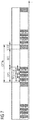
- Fig. 6 shows a timing diagram of a possible further exemplary embodiment of the scheduling method according to the first aspect of the present invention.
- each time slot S of the congestion protected section CPS of the common periodic time window CPTW comprises an associated time slot guard section.
- the congestion protected section CPS comprises four time slots S1, S2, S3, S4 used for synchronizing the endpoint nodes 4-1 to 4-4 of the exemplary network 1 shown in Figs. 1 , 2 .
- Each time slot S1, S2, S3, S4 of the congestion protected section CPS comprises an associated time slot guard section as illustrated in the timing diagram of Fig. 6 .
- the variant illustrated in Fig. 6 extends the previous shown variants by inserting small time slot guard sections in the protected section between the time slots S1, S2, S3, S4 and by extending slightly the best effort guard section BEGS.
- Fig. 7 shows a timing diagram for illustrating a further possible exemplary embodiment of the scheduling method according to the first aspect of the present invention.
- the embodiment uses a time-triggered periodic window CPTW with best effort section BES and a reduced best effort guard section BEGS.
- the variant illustrated in Fig. 7 extends the previous variants by applying a frame pre-emption technique to shrink the size of the best effort guard section BEGS.
- the best effort guard section BEGS can comprise a physical layer and/or a link layer guard section having a size corresponding to a fragment size of a data fragment of packets transmitted in the unpartitioned best effort section BES.
- a data packet transported in the best effort section BES can comprise eight data fragments each comprising 64 Byte.
- the best effort guard section BEGS comprises a size corresponding to the fragment size of the data fragment, i.e. 64 Byte.
- the illustrated embodiment further increases the efficiency and performance of the transmission system by shrinking the dead time of the guard section.
- fragments of the packet are sent out as long as they fit into the best-effort guard band. If a fragment does not fit into the best-effort guard section, it is pre-empted so that it cannot violate the periodic window and the congestion protected section.
- this example increases the transmission efficiency by decreasing the dead-time of the network where no traffic is allowed to flow.
- Fig. 8 shows a timing diagram for illustrating a further possible exemplary embodiment of the scheduling method according to the first aspect of the present invention.
- the previous variants of the scheduling method are extended by a method and system for bringing up or starting up the system in a start-up phase comprising several substeps.
- a first step 1 as illustrated in Fig. 8 of the start-up phase any traffic except synchronization traffic is blocked and the synchronization traffic comprising synchronization packets is handled in a best effort manner.
- a possible approach to accomplish this can be traffic filtering and gating similar to IEEE 802.1Qci.
- the synchronization packets are distributed by best effort handling.
- step 2 This can lead to congestions in the network which influences the accuracy of the packet-based time synchronization.
- step 2 this is taken into account in step 2 by setting up a periodic window scheduling, i.e. a common or global periodic time window CPTW within the network segments having a protected section that includes a large time slot guard section as illustrated in Fig. 8 .
- a periodic window scheduling i.e. a common or global periodic time window CPTW within the network segments having a protected section that includes a large time slot guard section as illustrated in Fig. 8 .
- the step 2 can be partitioned further into multiple substeps where the length of the time slot guard section is decreased from substep to substep.
- a normal operation with a scheduled transmission of packets within the common periodic time window CPTW is initiated as shown in Fig. 8 . Accordingly, a switchover to a normal operation mode is performed.
- This normal operation mode of the scheduling method according to the first aspect of the present invention is performed, i.e. the set-up common periodic time window CPTW comprises a congestion protected section CPS which is partitioned into time slots including time slots S dedicated to packets being sensitive to delay variation, in particular to synchronization packets.
- Fig. 9 shows a timing diagram for illustrating a possible exemplary embodiment for performing a time synchronization between nodes in a network segment.
- each network segment comprises a time master node 2 having a master time and slave nodes 3, 4 each having a slave time synchronized to each other by a packet-based synchronization mechanism.
- the synchronization packets transmitted to a node 3, 4 of the network segment can carry a time stamp T which may be generated by a time stamp generation unit of the respective node.
- the master node 2 comprising the master time transmits a synchronization packet to a slave node.
- the first synchronization packet does not carry a time stamp.
- the first synchronization packet can already comprise a time stamp T.
- the time stamps T known to the slave node are also illustrated.
- the slave node After having received a follow-up synchronization message from the master node 2, the slave node is aware of the time stamps T1, T2.
- the master node 2 After having sent a delay request message at time T3 to the master node 2, the master node 2 may send a delay response message carrying a time stamp T4 back to the slave node.
- the slave node knows four time stamps T1, T2, T3, T4 as illustrated in Fig. 9 .
- the slave node can adjust its internal clock according to the calculated mean path delay.
- Fig. 10 shows a further alternative implementation of a time synchronization mechanism which may be used for synchronizing nodes using the time scheduling method according to the first aspect of the present invention.
- An initiator such as the slave node 3 sends in the illustrated implementation a request message to a responder which can be formed by the master node. The request message is transmitted at time t1.
- the responder provides a time stamp when the message is received by the responder, i.e. time stamp T2. Then a response message is transmitted from the responder in opposite direction to the initiator.
- the response message carries the time stamp T2 and the time stamp T3 when the response message is sent back to the initiator. Further, the initiator provides a time stamp T4 upon receipt of the response message from the responder.
- a propagation delay is measured with the help of timestamping. Then, the node can correct the time offset.
- a globally synchronized and known periodic time window CPTW can comprise a congestion protected section CPS as a whole which is partitioned further in time slots S where dedicated time slots are allocated to packet delay variation sensitive data and dedicated time slots which are used for less or non-packet delay variation sensitive data.
- the scheduling method can be used in different kinds of networks, in particular in access networks of 5G mobile communication systems. Further, the scheduling method can be implemented in fronthaul networks, midhaul networks and/or backhaul networks.
- the invention further provides according to a third aspect a network node of a network wherein the node comprises ports each adapted to perform a scheduling method according to the first aspect of the present invention.
- the port is in a preferred embodiment an egress port of a network device or network element such as an endpoint node and/or a switch node or switching element of a network segment.
Landscapes
- Engineering & Computer Science (AREA)
- Computer Networks & Wireless Communication (AREA)
- Signal Processing (AREA)
- Databases & Information Systems (AREA)
- Mobile Radio Communication Systems (AREA)
- Synchronisation In Digital Transmission Systems (AREA)
- Small-Scale Networks (AREA)
Claims (23)
- Procédé de planification d'une transmission de paquets dans un réseau1.1 en utilisant une fenêtre temporelle périodique commune, CPTW, ayant une section protégée contre la congestion, CPS, divisée en créneaux temporels, S, incluant des créneaux temporels dédiés aux paquets sensibles à une variation de délai ;1.2 la fenêtre temporelle périodique commune, CPTW, étant une fenêtre temporelle périodique globale connue de chaque nœud du réseau ; et1.3 dans lequel la section protégée contre la congestion, CPS, de ladite fenêtre temporelle périodique commune, CPTW, comprend une section de synchronisation protégée contre la congestion, CPSS, divisée pour chaque nœud du réseau en créneaux temporels de liaison descendante et de liaison montante dédiés à la transmission de paquets de synchronisation utilisés pour la synchronisation temporelle et/ou fréquentielle desdits nœuds ; dans lequel1.4 les créneaux temporels dédiés aux paquets sensibles à une variation de délai sont les créneaux temporels de liaison descendante et de liaison montante dédiés à la transmission de paquets de synchronisation utilisés pour la synchronisation temporelle et/ou fréquentielle desdits nœuds.
- Procédé selon la revendication 1, dans lequel la section protégée contre la congestion, CPS, est divisée en créneaux temporels, S, incluant pour chaque nœud du réseau des créneaux temporels de liaison descendante et des créneaux temporels de liaison montante dédiés aux paquets sensibles à une variation de délai.
- Procédé selon l'une quelconque des revendications 1 à 2 précédentes, dans lequel la section protégée contre la congestion, CPS, de la fenêtre temporelle périodique commune, CPTW, comprend en outre une section de données protégée contre la congestion, CPDS, divisée en créneaux temporels, S, dédiés à d'autres paquets moins sensibles ou insensibles à une variation de délai,
lesdits autres paquets comprenant des paquets de données et/ou des paquets de commande. - Procédé selon l'une quelconque des revendications 1 à 3 précédentes, dans lequel la fenêtre temporelle périodique commune, CPTW, comprend la section protégée contre la congestion, CPS, une section de meilleur effort non partitionnée, BES, et une section de garde de meilleur effort non partitionnée, BEGS.
- Procédé selon la revendication 4, dans lequel la section de garde de meilleur effort non partitionnée, BEGS, comprend une couche physique et/ou une section de garde de couche de liaison ayant une taille correspondant à une taille de fragment d'un fragment de données de paquets transmis dans ladite section de meilleur effort non partitionnée, BES.
- Procédé selon l'une quelconque des revendications 1 à 5 précédentes, dans lequel chaque créneau temporel, S, de la section protégée contre la congestion, CPS, de la fenêtre temporelle périodique commune, CPTW, comprend une section de garde de créneau temporel associée.
- Procédé selon l'une quelconque des revendications 1 et 3 à 6 précédentes, dans lequel les paquets moins sensibles ou insensibles aux variations de délai sont classés par ordre de priorité en fonction des priorités de transmission attribuées.
- Procédé selon l'une quelconque des revendications 1 à 7 précédentes, dans lequel une latence introduite par la fenêtre temporelle périodique commune utilisée, CPTW, est déterministe et est automatiquement compensée pour minimiser une variation de délai dans le réseau.
- Procédé selon l'une quelconque des revendications 1 et 3 à 8 précédentes, dans lequel le paquet de synchronisation transmis par un nœud du réseau porte un horodatage généré par une unité de génération d'horodatage du nœud respectif.
- Procédé selon l'une quelconque des revendications 1 à 9 précédentes, dans lequel la durée de la fenêtre temporelle périodique commune, CPTW, et/ou la durée des créneaux temporels, S, est préconfigurée ou ajustée de manière adaptative pendant le fonctionnement du réseau.
- Procédé selon l'une quelconque des revendications 1 à 10 précédentes, dans lequel le réseau comprend au moins un segment de réseau ayant un nœud maître temporel et au moins un nœud esclave,
dans lequel le nœud maître temporel et le nœud esclave échangent des paquets de synchronisation l'un avec l'autre pendant des créneaux temporels, S, de la section de synchronisation protégée contre la congestion, CPSS, de ladite fenêtre temporelle périodique commune, CPTW, dédiés à la synchronisation du nœud esclave respectif. - Procédé selon la revendication 11, dans lequel le nœud maître temporel du segment de réseau transmet des paquets de synchronisation de manière unidirectionnelle à un nœud esclave dudit segment de réseau pendant un créneau temporel de liaison descendante d'une section de synchronisation protégée contre la congestion, CPSS, de ladite fenêtre temporelle périodique commune, CPTW, dédié à la synchronisation du nœud esclave respectif et dans lequel un nœud esclave du segment de réseau transmet des paquets de synchronisation de manière unidirectionnelle au nœud maître temporel dudit segment de réseau pendant un créneau temporel de liaison montante de la section de synchronisation protégée contre la congestion, CPSS, de ladite fenêtre temporelle périodique commune, CPTW, dédié à la synchronisation du nœud esclave respectif.
- Procédé selon l'une quelconque des revendications 3 à 12 précédentes, dans lequel les paquets de données et/ou les paquets de commande sont échangés entre des nœuds esclaves d'un segment de réseau du réseau pendant au moins un créneau temporel de la section de données protégée contre la congestion, CPDS, de ladite fenêtre temporelle périodique commune, CPTW, dédié à un canal de communication bidirectionnel entre les deux nœuds esclaves.
- Procédé selon la revendication 13, dans lequel un nœud esclave d'un segment de réseau transmet de manière unidirectionnelle des paquets de données et/ou des paquets de commande à un autre nœud esclave dudit segment de réseau pendant un premier créneau temporel de la section de données protégée contre la congestion, CPDS, de ladite fenêtre temporelle périodique commune, CPTW, dédié à un canal de communication bidirectionnelle, CC, entre les deux nœuds esclaves dudit segment de réseau et dans lequel l'autre nœud esclave du segment de réseau transmet de manière unidirectionnelle des paquets de données et/ou des paquets de commande au nœud esclave respectif pendant un deuxième créneau temporel de la section de données protégée contre la congestion, CPDS, de la fenêtre temporelle périodique commune, CPTW, dédié au canal de communication bidirectionnelle, CC, entre les deux nœuds esclaves dudit segment de réseau.
- Procédé selon l'une quelconque des revendications précédentes, dans lequel des paquets échangés entre des nœuds esclaves d'un segment de réseau sont transmis saut par saut via des lignes de signaux et des commutateurs de réseau du réseau,
dans lequel une latence supplémentaire introduite par les lignes de signaux et les commutateurs de réseau est minimisée en décalant les créneaux temporels dédiés aux paquets respectifs dans la fenêtre temporelle périodique commune, CPTW, saut par saut pour compenser la latence supplémentaire. - Procédé selon l'une quelconque des revendications 1 à 15 précédentes, comprenant une phase de démarrage,
dans lequel, dans une première étape de ladite phase de démarrage, tout trafic, à l'exception du trafic de synchronisation, est bloqué et le trafic de synchronisation comprenant des paquets de synchronisation est traité selon le principe du meilleur effort,
dans lequel, dans une deuxième étape de ladite phase de démarrage, une fenêtre temporelle périodique commune, CPTW, ayant une section protégée contre la congestion, CPS, divisée en créneaux temporels, S, pour le trafic de synchronisation et ayant une section de garde de créneau temporel est établie et dans lequel, dans une troisième étape de ladite phase de démarrage, un fonctionnement normal avec une transmission planifiée de paquets dans la fenêtre temporelle périodique commune CPTW, est initié. - Procédé selon l'une quelconque des revendications 1 à 15 précédentes, comprenant une phase de démarrage,
dans lequel, dans une première étape de ladite phase de démarrage, tout trafic, à l'exception du trafic de synchronisation, est bloqué et le trafic de synchronisation comprenant des paquets de synchronisation est traité selon le principe du meilleur effort, et
dans lequel, dans une autre étape de ladite phase de démarrage, un fonctionnement normal avec une transmission planifiée de paquets dans une fenêtre temporelle périodique commune, CPTW, est initié. - Procédé selon la revendication 16, dans lequel la deuxième étape de ladite phase de démarrage est en outre divisée en sous-étapes, la longueur de la section de garde de créneau temporel étant diminuée d'une sous-étape à l'autre en fonction de la précision de synchronisation.
- Réseau (1) comprenant des nœuds (2, 3, 4) dont chacun est adapté à exécuter un procédé de planification selon l'une quelconque des revendications 1 à 18 précédentes.
- Réseau selon la revendication 19, dans lequel le réseau (1) comprend :un réseau d'accès,un réseau fronthaul,un réseau midhaul,un réseau backhaul et/ouun réseau de communication mobile 5G.
- Réseau selon la revendication 19 ou 20, dans lequel le réseau (1) est un réseau à déclenchement temporel comprenant un ou plusieurs segments de réseau comprenant chacun un nœud maître temporel (2) et des nœuds esclaves (4) synchronisés entre eux par un mécanisme de synchronisation par paquets.
- Réseau selon la revendication 21, dans lequel le nœud esclave (4) comprend une tête radio distante, RRH, (4-1, 4-2) ou une unité de bande de base, BBU, (4-3, 4-4).
- Nœud d'un réseau (1), ledit nœud (2, 3, 4) comprenant des ports adaptés chacun à exécuter un procédé de planification selon l'une quelconque des revendications 1 à 18 précédentes.
Priority Applications (2)
| Application Number | Priority Date | Filing Date | Title |
|---|---|---|---|
| EP16187925.9A EP3294014B1 (fr) | 2016-09-08 | 2016-09-08 | Procédé permettant de programmer une transmission de paquets dans un réseau |
| US15/691,261 US10433325B2 (en) | 2016-09-08 | 2017-08-30 | Method for scheduling a transmission of packets within a network |
Applications Claiming Priority (1)
| Application Number | Priority Date | Filing Date | Title |
|---|---|---|---|
| EP16187925.9A EP3294014B1 (fr) | 2016-09-08 | 2016-09-08 | Procédé permettant de programmer une transmission de paquets dans un réseau |
Publications (2)
| Publication Number | Publication Date |
|---|---|
| EP3294014A1 EP3294014A1 (fr) | 2018-03-14 |
| EP3294014B1 true EP3294014B1 (fr) | 2019-12-18 |
Family
ID=56936287
Family Applications (1)
| Application Number | Title | Priority Date | Filing Date |
|---|---|---|---|
| EP16187925.9A Active EP3294014B1 (fr) | 2016-09-08 | 2016-09-08 | Procédé permettant de programmer une transmission de paquets dans un réseau |
Country Status (2)
| Country | Link |
|---|---|
| US (1) | US10433325B2 (fr) |
| EP (1) | EP3294014B1 (fr) |
Families Citing this family (22)
| Publication number | Priority date | Publication date | Assignee | Title |
|---|---|---|---|---|
| US10231256B2 (en) * | 2016-02-12 | 2019-03-12 | Microelectronics Technology Inc. | Method for radio source scheduling |
| EP3533253B1 (fr) * | 2016-10-26 | 2021-08-18 | Telefonaktiebolaget LM Ericsson (PUBL) | Régulation d'encombrement 5g |
| US10609054B2 (en) | 2017-04-07 | 2020-03-31 | Keysight Technologies Singapore (Sales) Pte. Ltd. | Methods, systems, and computer readable media for monitoring, adjusting, and utilizing latency associated with accessing distributed computing resources |
| WO2018189726A1 (fr) * | 2017-04-13 | 2018-10-18 | Telefonaktiebolaget Lm Ericsson (Publ) | Algorithme de planification distribuée pour cpri par ethernet |
| US10425321B2 (en) * | 2017-04-25 | 2019-09-24 | Keysight Technologies Singapore (Sales) Pte. Ltd. | Methods, systems, and computer readable media for testing time sensitive network (TSN) elements |
| WO2019091587A1 (fr) * | 2017-11-13 | 2019-05-16 | Telefonaktiebolaget Lm Ericsson (Publ) | Procédé et appareil pour gérer le transport de paquets sensibles au retard |
| CN108809617B (zh) * | 2018-04-18 | 2021-12-14 | 京信网络系统股份有限公司 | 一种时延补偿方法及终端 |
| US10785082B2 (en) | 2018-09-19 | 2020-09-22 | Solid, Inc. | Distributed antenna system-based on time sensitive network |
| US10912101B2 (en) * | 2018-11-12 | 2021-02-02 | General Electric Company | Frequency-based communication system and method |
| US10965392B2 (en) | 2019-01-25 | 2021-03-30 | Keysight Technologies, Inc. | Active network tap supporting time sensitive network (TSN) standards |
| US11563768B2 (en) | 2019-01-31 | 2023-01-24 | Keysight Technologies, Inc. | Methods, systems, and computer readable media for detecting and mitigating effects of timing attacks in time sensitive networks |
| US12185036B2 (en) * | 2019-04-29 | 2024-12-31 | Telefonaktiebolaget Lm Ericsson (Publ) | Method and apparatus for controlling transmission of an upstream packet traffic in a TDM PON-based fronthaul |
| US11502932B2 (en) | 2019-05-17 | 2022-11-15 | Keysight Technologies, Inc. | Indirect testing using impairment rules |
| DE102019005681A1 (de) * | 2019-08-13 | 2021-02-18 | Diehl Metering Systems Gmbh | Verfahren zum bidirektionalen Übertragen von Daten, insbesondere Sensordaten sowie funkfähiger Knoten |
| US11444831B2 (en) | 2020-01-17 | 2022-09-13 | Keysight Technologies, Inc. | Methods, systems, and computer readable media for measuring schedule update time for a time aware shaper implementation |
| CN113543082B (zh) * | 2020-04-22 | 2023-12-08 | 北京猎户星空科技有限公司 | 一种通信方法、装置、电子设备、系统以及介质 |
| WO2021257526A1 (fr) * | 2020-06-18 | 2021-12-23 | John Mezzalingua Associates, LLC | Réseau radio intégré à capacité de liaison fronthaul multi-opérateurs et multi-formats de signal |
| CN113595769B (zh) * | 2021-07-09 | 2022-06-07 | 武汉大学 | 一种跳变网络多节点网络延迟时间窗计算方法 |
| US12438814B2 (en) * | 2022-09-28 | 2025-10-07 | Mediatek Inc. | Wireless signal transmission management method and system |
| US11729019B1 (en) * | 2022-10-05 | 2023-08-15 | GM Global Technology Operations LLC | Systems and methods for scheduling periodic message transmission |
| CN116470981A (zh) * | 2023-03-31 | 2023-07-21 | 北京百度网讯科技有限公司 | 时间同步方法、装置、设备以及存储介质 |
| US12063287B1 (en) | 2023-04-27 | 2024-08-13 | Keysight Technologies, Inc. | Methods, systems, and computer readable media for determining an internal time of a time-sensitive networking (TSN) network card |
Family Cites Families (12)
| Publication number | Priority date | Publication date | Assignee | Title |
|---|---|---|---|---|
| FI110903B (fi) * | 2000-10-30 | 2003-04-15 | Nokia Corp | Lähetysten ajoittaminen tietoliikennejärjestelmässä |
| US8621313B2 (en) * | 2010-04-06 | 2013-12-31 | Canon Kabushiki Kaisha | Method and a device for adapting error protection in a communication network, and a method and device for detecting between two states of a communication network corresponding to different losses of data |
| EP2586142B1 (fr) * | 2010-07-07 | 2017-05-03 | Huawei Technologies Co., Ltd. | Placement déterministe de paquets à estampille temporelle utilisant une discontinuité périodique |
| FR2967535B1 (fr) * | 2010-11-15 | 2012-11-02 | Alcatel Lucent | Procede de synchronisation d'horloges maitre et esclave d'un reseau a commutation de paquets et a liaisons agregees entre noeuds, et dispositifs de synchronisation associes |
| KR20140053860A (ko) * | 2011-02-09 | 2014-05-08 | 인터디지탈 패튼 홀딩스, 인크 | 통합 코디네이터를 구비한 구성가능한 아키텍쳐 |
| US8787325B2 (en) * | 2012-09-19 | 2014-07-22 | St-Ericsson Sa | Scheduling best effort traffic with guaranteed latency traffic in a communications system having a bluetooth-like packet communication protocol |
| US20160212042A1 (en) * | 2013-08-19 | 2016-07-21 | Lg Electronics Inc. | Broadcast transmitting device, broadcast receiving device, operating method of the broadcast transmitting device, and operating method of the broadcast receiving device |
| US9451563B2 (en) * | 2014-10-16 | 2016-09-20 | Qualcomm Incorporated | Techniques for energy detection level adjustments |
| US9668194B2 (en) * | 2015-01-30 | 2017-05-30 | Huawei Technologies Co., Ltd. | System and method for coordinating device-to-device communications |
| WO2016126099A1 (fr) * | 2015-02-05 | 2016-08-11 | 엘지전자(주) | Procédé destiné à une rétroaction csi dans un système de communication sans fil et appareil s'y rapportant |
| WO2016168603A1 (fr) * | 2015-04-15 | 2016-10-20 | Nokia Solutions And Networks Oy | Concepts de réseau auto-organisateur pour liaison terrestre de petites cellules |
| US10305788B2 (en) * | 2016-06-30 | 2019-05-28 | Alcatel Lucent | Near-real-time and real-time communications |
-
2016
- 2016-09-08 EP EP16187925.9A patent/EP3294014B1/fr active Active
-
2017
- 2017-08-30 US US15/691,261 patent/US10433325B2/en active Active
Non-Patent Citations (1)
| Title |
|---|
| None * |
Also Published As
| Publication number | Publication date |
|---|---|
| US10433325B2 (en) | 2019-10-01 |
| EP3294014A1 (fr) | 2018-03-14 |
| US20180070373A1 (en) | 2018-03-08 |
Similar Documents
| Publication | Publication Date | Title |
|---|---|---|
| EP3294014B1 (fr) | Procédé permettant de programmer une transmission de paquets dans un réseau | |
| KR102800334B1 (ko) | 이동통신망에서 패킷 처리 방법 및 이를 수행하는 네트워크 엘리먼트 | |
| US9882823B2 (en) | Systems and methods for blocking transmission of a frame in a network device | |
| US9960872B2 (en) | Systems and methods for performing a soft-block of a queue based on a size of a remaining period of a guard band | |
| US8982897B2 (en) | Data block output apparatus, communication system, data block output method, and communication method | |
| US11088962B2 (en) | Method for performant data transmission in a data network with, in part, real-time requirements and apparatus for carrying out the method | |
| Alderisi et al. | Introducing support for scheduled traffic over IEEE audio video bridging networks | |
| CN110546926B (zh) | 减少时间敏感分组的分组延迟变化 | |
| US10764201B2 (en) | System and method for scheduling communications | |
| EP3278518B1 (fr) | Noeud de réseau | |
| US10924373B2 (en) | Optical line terminal of optical network and uplink scheduling method | |
| US10361962B2 (en) | Packet processing technique for a communication network | |
| US20120099432A1 (en) | Decreasing jitter in packetized communication systems | |
| EP2323317A1 (fr) | Procédé de commande de bande et dispositif de commande de bande pour dispositif de n ud | |
| US11785635B2 (en) | Communication system enabled to minimize negative communication effects | |
| EP3591929A1 (fr) | Garantie de fonctionnement d'un réseau de communication dans le cas d'un état anormal de la circulation | |
| EP3731575B1 (fr) | Procédé de synchronisation d'horloge de protocoles et réseau, station de base et équipements utilisateur | |
| US9853909B2 (en) | Methods and apparatus for traffic management in a communication network | |
| US20070025385A1 (en) | Residential ethernet node device for transmitting synchronous data using counter and synchronous data transmitting method thereof | |
| JP2018098548A (ja) | Ponシステム、olt、onuおよび通信方法 |
Legal Events
| Date | Code | Title | Description |
|---|---|---|---|
| PUAI | Public reference made under article 153(3) epc to a published international application that has entered the european phase |
Free format text: ORIGINAL CODE: 0009012 |
|
| STAA | Information on the status of an ep patent application or granted ep patent |
Free format text: STATUS: THE APPLICATION HAS BEEN PUBLISHED |
|
| AK | Designated contracting states |
Kind code of ref document: A1 Designated state(s): AL AT BE BG CH CY CZ DE DK EE ES FI FR GB GR HR HU IE IS IT LI LT LU LV MC MK MT NL NO PL PT RO RS SE SI SK SM TR |
|
| AX | Request for extension of the european patent |
Extension state: BA ME |
|
| STAA | Information on the status of an ep patent application or granted ep patent |
Free format text: STATUS: REQUEST FOR EXAMINATION WAS MADE |
|
| 17P | Request for examination filed |
Effective date: 20180412 |
|
| RBV | Designated contracting states (corrected) |
Designated state(s): AL AT BE BG CH CY CZ DE DK EE ES FI FR GB GR HR HU IE IS IT LI LT LU LV MC MK MT NL NO PL PT RO RS SE SI SK SM TR |
|
| STAA | Information on the status of an ep patent application or granted ep patent |
Free format text: STATUS: EXAMINATION IS IN PROGRESS |
|
| RIC1 | Information provided on ipc code assigned before grant |
Ipc: H04W 72/12 20090101ALI20190320BHEP Ipc: H04W 28/02 20090101ALI20190320BHEP Ipc: H04L 7/00 20060101ALI20190320BHEP Ipc: H04L 12/801 20130101ALI20190320BHEP Ipc: H04L 29/08 20060101ALI20190320BHEP Ipc: H04W 88/08 20090101ALN20190320BHEP Ipc: H04W 56/00 20090101AFI20190320BHEP |
|
| RIC1 | Information provided on ipc code assigned before grant |
Ipc: H04W 28/02 20090101ALI20190329BHEP Ipc: H04W 56/00 20090101AFI20190329BHEP Ipc: H04L 7/00 20060101ALI20190329BHEP Ipc: H04W 72/12 20090101ALI20190329BHEP Ipc: H04W 88/08 20090101ALN20190329BHEP Ipc: H04L 12/801 20130101ALI20190329BHEP Ipc: H04L 29/08 20060101ALI20190329BHEP |
|
| 17Q | First examination report despatched |
Effective date: 20190411 |
|
| GRAP | Despatch of communication of intention to grant a patent |
Free format text: ORIGINAL CODE: EPIDOSNIGR1 |
|
| STAA | Information on the status of an ep patent application or granted ep patent |
Free format text: STATUS: GRANT OF PATENT IS INTENDED |
|
| RIC1 | Information provided on ipc code assigned before grant |
Ipc: H04W 72/12 20090101ALI20190718BHEP Ipc: H04W 28/02 20090101ALI20190718BHEP Ipc: H04L 12/801 20130101ALI20190718BHEP Ipc: H04W 88/08 20090101ALN20190718BHEP Ipc: H04W 56/00 20090101AFI20190718BHEP Ipc: H04L 29/08 20060101ALI20190718BHEP Ipc: H04L 7/00 20060101ALI20190718BHEP |
|
| INTG | Intention to grant announced |
Effective date: 20190812 |
|
| GRAS | Grant fee paid |
Free format text: ORIGINAL CODE: EPIDOSNIGR3 |
|
| GRAA | (expected) grant |
Free format text: ORIGINAL CODE: 0009210 |
|
| STAA | Information on the status of an ep patent application or granted ep patent |
Free format text: STATUS: THE PATENT HAS BEEN GRANTED |
|
| AK | Designated contracting states |
Kind code of ref document: B1 Designated state(s): AL AT BE BG CH CY CZ DE DK EE ES FI FR GB GR HR HU IE IS IT LI LT LU LV MC MK MT NL NO PL PT RO RS SE SI SK SM TR |
|
| REG | Reference to a national code |
Ref country code: CH Ref legal event code: EP |
|
| REG | Reference to a national code |
Ref country code: IE Ref legal event code: FG4D |
|
| REG | Reference to a national code |
Ref country code: DE Ref legal event code: R096 Ref document number: 602016026289 Country of ref document: DE |
|
| REG | Reference to a national code |
Ref country code: AT Ref legal event code: REF Ref document number: 1216000 Country of ref document: AT Kind code of ref document: T Effective date: 20200115 |
|
| REG | Reference to a national code |
Ref country code: NL Ref legal event code: MP Effective date: 20191218 |
|
| PG25 | Lapsed in a contracting state [announced via postgrant information from national office to epo] |
Ref country code: SE Free format text: LAPSE BECAUSE OF FAILURE TO SUBMIT A TRANSLATION OF THE DESCRIPTION OR TO PAY THE FEE WITHIN THE PRESCRIBED TIME-LIMIT Effective date: 20191218 Ref country code: LV Free format text: LAPSE BECAUSE OF FAILURE TO SUBMIT A TRANSLATION OF THE DESCRIPTION OR TO PAY THE FEE WITHIN THE PRESCRIBED TIME-LIMIT Effective date: 20191218 Ref country code: BG Free format text: LAPSE BECAUSE OF FAILURE TO SUBMIT A TRANSLATION OF THE DESCRIPTION OR TO PAY THE FEE WITHIN THE PRESCRIBED TIME-LIMIT Effective date: 20200318 Ref country code: FI Free format text: LAPSE BECAUSE OF FAILURE TO SUBMIT A TRANSLATION OF THE DESCRIPTION OR TO PAY THE FEE WITHIN THE PRESCRIBED TIME-LIMIT Effective date: 20191218 Ref country code: GR Free format text: LAPSE BECAUSE OF FAILURE TO SUBMIT A TRANSLATION OF THE DESCRIPTION OR TO PAY THE FEE WITHIN THE PRESCRIBED TIME-LIMIT Effective date: 20200319 Ref country code: LT Free format text: LAPSE BECAUSE OF FAILURE TO SUBMIT A TRANSLATION OF THE DESCRIPTION OR TO PAY THE FEE WITHIN THE PRESCRIBED TIME-LIMIT Effective date: 20191218 Ref country code: NO Free format text: LAPSE BECAUSE OF FAILURE TO SUBMIT A TRANSLATION OF THE DESCRIPTION OR TO PAY THE FEE WITHIN THE PRESCRIBED TIME-LIMIT Effective date: 20200318 |
|
| REG | Reference to a national code |
Ref country code: LT Ref legal event code: MG4D |
|
| PG25 | Lapsed in a contracting state [announced via postgrant information from national office to epo] |
Ref country code: RS Free format text: LAPSE BECAUSE OF FAILURE TO SUBMIT A TRANSLATION OF THE DESCRIPTION OR TO PAY THE FEE WITHIN THE PRESCRIBED TIME-LIMIT Effective date: 20191218 Ref country code: HR Free format text: LAPSE BECAUSE OF FAILURE TO SUBMIT A TRANSLATION OF THE DESCRIPTION OR TO PAY THE FEE WITHIN THE PRESCRIBED TIME-LIMIT Effective date: 20191218 |
|
| PG25 | Lapsed in a contracting state [announced via postgrant information from national office to epo] |
Ref country code: AL Free format text: LAPSE BECAUSE OF FAILURE TO SUBMIT A TRANSLATION OF THE DESCRIPTION OR TO PAY THE FEE WITHIN THE PRESCRIBED TIME-LIMIT Effective date: 20191218 |
|
| PG25 | Lapsed in a contracting state [announced via postgrant information from national office to epo] |
Ref country code: CZ Free format text: LAPSE BECAUSE OF FAILURE TO SUBMIT A TRANSLATION OF THE DESCRIPTION OR TO PAY THE FEE WITHIN THE PRESCRIBED TIME-LIMIT Effective date: 20191218 Ref country code: RO Free format text: LAPSE BECAUSE OF FAILURE TO SUBMIT A TRANSLATION OF THE DESCRIPTION OR TO PAY THE FEE WITHIN THE PRESCRIBED TIME-LIMIT Effective date: 20191218 Ref country code: PT Free format text: LAPSE BECAUSE OF FAILURE TO SUBMIT A TRANSLATION OF THE DESCRIPTION OR TO PAY THE FEE WITHIN THE PRESCRIBED TIME-LIMIT Effective date: 20200513 Ref country code: NL Free format text: LAPSE BECAUSE OF FAILURE TO SUBMIT A TRANSLATION OF THE DESCRIPTION OR TO PAY THE FEE WITHIN THE PRESCRIBED TIME-LIMIT Effective date: 20191218 Ref country code: EE Free format text: LAPSE BECAUSE OF FAILURE TO SUBMIT A TRANSLATION OF THE DESCRIPTION OR TO PAY THE FEE WITHIN THE PRESCRIBED TIME-LIMIT Effective date: 20191218 |
|
| PG25 | Lapsed in a contracting state [announced via postgrant information from national office to epo] |
Ref country code: IS Free format text: LAPSE BECAUSE OF FAILURE TO SUBMIT A TRANSLATION OF THE DESCRIPTION OR TO PAY THE FEE WITHIN THE PRESCRIBED TIME-LIMIT Effective date: 20200418 Ref country code: SK Free format text: LAPSE BECAUSE OF FAILURE TO SUBMIT A TRANSLATION OF THE DESCRIPTION OR TO PAY THE FEE WITHIN THE PRESCRIBED TIME-LIMIT Effective date: 20191218 Ref country code: SM Free format text: LAPSE BECAUSE OF FAILURE TO SUBMIT A TRANSLATION OF THE DESCRIPTION OR TO PAY THE FEE WITHIN THE PRESCRIBED TIME-LIMIT Effective date: 20191218 |
|
| REG | Reference to a national code |
Ref country code: DE Ref legal event code: R097 Ref document number: 602016026289 Country of ref document: DE |
|
| REG | Reference to a national code |
Ref country code: AT Ref legal event code: MK05 Ref document number: 1216000 Country of ref document: AT Kind code of ref document: T Effective date: 20191218 |
|
| PLBE | No opposition filed within time limit |
Free format text: ORIGINAL CODE: 0009261 |
|
| STAA | Information on the status of an ep patent application or granted ep patent |
Free format text: STATUS: NO OPPOSITION FILED WITHIN TIME LIMIT |
|
| PG25 | Lapsed in a contracting state [announced via postgrant information from national office to epo] |
Ref country code: DK Free format text: LAPSE BECAUSE OF FAILURE TO SUBMIT A TRANSLATION OF THE DESCRIPTION OR TO PAY THE FEE WITHIN THE PRESCRIBED TIME-LIMIT Effective date: 20191218 Ref country code: ES Free format text: LAPSE BECAUSE OF FAILURE TO SUBMIT A TRANSLATION OF THE DESCRIPTION OR TO PAY THE FEE WITHIN THE PRESCRIBED TIME-LIMIT Effective date: 20191218 |
|
| 26N | No opposition filed |
Effective date: 20200921 |
|
| PG25 | Lapsed in a contracting state [announced via postgrant information from national office to epo] |
Ref country code: SI Free format text: LAPSE BECAUSE OF FAILURE TO SUBMIT A TRANSLATION OF THE DESCRIPTION OR TO PAY THE FEE WITHIN THE PRESCRIBED TIME-LIMIT Effective date: 20191218 Ref country code: AT Free format text: LAPSE BECAUSE OF FAILURE TO SUBMIT A TRANSLATION OF THE DESCRIPTION OR TO PAY THE FEE WITHIN THE PRESCRIBED TIME-LIMIT Effective date: 20191218 |
|
| PG25 | Lapsed in a contracting state [announced via postgrant information from national office to epo] |
Ref country code: IT Free format text: LAPSE BECAUSE OF FAILURE TO SUBMIT A TRANSLATION OF THE DESCRIPTION OR TO PAY THE FEE WITHIN THE PRESCRIBED TIME-LIMIT Effective date: 20191218 |
|
| PG25 | Lapsed in a contracting state [announced via postgrant information from national office to epo] |
Ref country code: PL Free format text: LAPSE BECAUSE OF FAILURE TO SUBMIT A TRANSLATION OF THE DESCRIPTION OR TO PAY THE FEE WITHIN THE PRESCRIBED TIME-LIMIT Effective date: 20191218 |
|
| REG | Reference to a national code |
Ref country code: CH Ref legal event code: PL |
|
| REG | Reference to a national code |
Ref country code: BE Ref legal event code: MM Effective date: 20200930 |
|
| PG25 | Lapsed in a contracting state [announced via postgrant information from national office to epo] |
Ref country code: LU Free format text: LAPSE BECAUSE OF NON-PAYMENT OF DUE FEES Effective date: 20200908 |
|
| PG25 | Lapsed in a contracting state [announced via postgrant information from national office to epo] |
Ref country code: FR Free format text: LAPSE BECAUSE OF NON-PAYMENT OF DUE FEES Effective date: 20200930 |
|
| PG25 | Lapsed in a contracting state [announced via postgrant information from national office to epo] |
Ref country code: LI Free format text: LAPSE BECAUSE OF NON-PAYMENT OF DUE FEES Effective date: 20200930 Ref country code: IE Free format text: LAPSE BECAUSE OF NON-PAYMENT OF DUE FEES Effective date: 20200908 Ref country code: BE Free format text: LAPSE BECAUSE OF NON-PAYMENT OF DUE FEES Effective date: 20200930 Ref country code: CH Free format text: LAPSE BECAUSE OF NON-PAYMENT OF DUE FEES Effective date: 20200930 |
|
| PG25 | Lapsed in a contracting state [announced via postgrant information from national office to epo] |
Ref country code: TR Free format text: LAPSE BECAUSE OF FAILURE TO SUBMIT A TRANSLATION OF THE DESCRIPTION OR TO PAY THE FEE WITHIN THE PRESCRIBED TIME-LIMIT Effective date: 20191218 Ref country code: MT Free format text: LAPSE BECAUSE OF FAILURE TO SUBMIT A TRANSLATION OF THE DESCRIPTION OR TO PAY THE FEE WITHIN THE PRESCRIBED TIME-LIMIT Effective date: 20191218 Ref country code: CY Free format text: LAPSE BECAUSE OF FAILURE TO SUBMIT A TRANSLATION OF THE DESCRIPTION OR TO PAY THE FEE WITHIN THE PRESCRIBED TIME-LIMIT Effective date: 20191218 |
|
| PG25 | Lapsed in a contracting state [announced via postgrant information from national office to epo] |
Ref country code: MK Free format text: LAPSE BECAUSE OF FAILURE TO SUBMIT A TRANSLATION OF THE DESCRIPTION OR TO PAY THE FEE WITHIN THE PRESCRIBED TIME-LIMIT Effective date: 20191218 Ref country code: MC Free format text: LAPSE BECAUSE OF FAILURE TO SUBMIT A TRANSLATION OF THE DESCRIPTION OR TO PAY THE FEE WITHIN THE PRESCRIBED TIME-LIMIT Effective date: 20191218 |
|
| P01 | Opt-out of the competence of the unified patent court (upc) registered |
Effective date: 20230630 |
|
| REG | Reference to a national code |
Ref country code: DE Ref legal event code: R081 Ref document number: 602016026289 Country of ref document: DE Owner name: ADTRAN NETWORKS SE, DE Free format text: FORMER OWNER: ADVA OPTICAL NETWORKING SE, 98617 MEININGEN, DE |
|
| PGFP | Annual fee paid to national office [announced via postgrant information from national office to epo] |
Ref country code: DE Payment date: 20250919 Year of fee payment: 10 |
|
| PGFP | Annual fee paid to national office [announced via postgrant information from national office to epo] |
Ref country code: GB Payment date: 20250923 Year of fee payment: 10 |