EP2586333B2 - Auszugsführung - Google Patents
Auszugsführung Download PDFInfo
- Publication number
- EP2586333B2 EP2586333B2 EP13152813.5A EP13152813A EP2586333B2 EP 2586333 B2 EP2586333 B2 EP 2586333B2 EP 13152813 A EP13152813 A EP 13152813A EP 2586333 B2 EP2586333 B2 EP 2586333B2
- Authority
- EP
- European Patent Office
- Prior art keywords
- lubricant
- pull
- rolling
- containing material
- rail
- Prior art date
- Legal status (The legal status is an assumption and is not a legal conclusion. Google has not performed a legal analysis and makes no representation as to the accuracy of the status listed.)
- Active
Links
Images




Classifications
-
- F—MECHANICAL ENGINEERING; LIGHTING; HEATING; WEAPONS; BLASTING
- F16—ENGINEERING ELEMENTS AND UNITS; GENERAL MEASURES FOR PRODUCING AND MAINTAINING EFFECTIVE FUNCTIONING OF MACHINES OR INSTALLATIONS; THERMAL INSULATION IN GENERAL
- F16C—SHAFTS; FLEXIBLE SHAFTS; ELEMENTS OR CRANKSHAFT MECHANISMS; ROTARY BODIES OTHER THAN GEARING ELEMENTS; BEARINGS
- F16C33/00—Parts of bearings; Special methods for making bearings or parts thereof
- F16C33/30—Parts of ball or roller bearings
- F16C33/38—Ball cages
- F16C33/44—Selection of substances
-
- A—HUMAN NECESSITIES
- A47—FURNITURE; DOMESTIC ARTICLES OR APPLIANCES; COFFEE MILLS; SPICE MILLS; SUCTION CLEANERS IN GENERAL
- A47B—TABLES; DESKS; OFFICE FURNITURE; CABINETS; DRAWERS; GENERAL DETAILS OF FURNITURE
- A47B88/00—Drawers for tables, cabinets or like furniture; Guides for drawers
- A47B88/40—Sliding drawers; Slides or guides therefor
- A47B88/483—Sliding drawers; Slides or guides therefor with single extensible guides or parts
- A47B88/487—Sliding drawers; Slides or guides therefor with single extensible guides or parts with rollers, ball bearings, wheels, or the like
-
- A—HUMAN NECESSITIES
- A47—FURNITURE; DOMESTIC ARTICLES OR APPLIANCES; COFFEE MILLS; SPICE MILLS; SUCTION CLEANERS IN GENERAL
- A47B—TABLES; DESKS; OFFICE FURNITURE; CABINETS; DRAWERS; GENERAL DETAILS OF FURNITURE
- A47B88/00—Drawers for tables, cabinets or like furniture; Guides for drawers
- A47B88/40—Sliding drawers; Slides or guides therefor
- A47B88/49—Sliding drawers; Slides or guides therefor with double extensible guides or parts
- A47B88/493—Sliding drawers; Slides or guides therefor with double extensible guides or parts with rollers, ball bearings, wheels, or the like
-
- F—MECHANICAL ENGINEERING; LIGHTING; HEATING; WEAPONS; BLASTING
- F16—ENGINEERING ELEMENTS AND UNITS; GENERAL MEASURES FOR PRODUCING AND MAINTAINING EFFECTIVE FUNCTIONING OF MACHINES OR INSTALLATIONS; THERMAL INSULATION IN GENERAL
- F16C—SHAFTS; FLEXIBLE SHAFTS; ELEMENTS OR CRANKSHAFT MECHANISMS; ROTARY BODIES OTHER THAN GEARING ELEMENTS; BEARINGS
- F16C29/00—Bearings for parts moving only linearly
- F16C29/04—Ball or roller bearings
-
- F—MECHANICAL ENGINEERING; LIGHTING; HEATING; WEAPONS; BLASTING
- F16—ENGINEERING ELEMENTS AND UNITS; GENERAL MEASURES FOR PRODUCING AND MAINTAINING EFFECTIVE FUNCTIONING OF MACHINES OR INSTALLATIONS; THERMAL INSULATION IN GENERAL
- F16C—SHAFTS; FLEXIBLE SHAFTS; ELEMENTS OR CRANKSHAFT MECHANISMS; ROTARY BODIES OTHER THAN GEARING ELEMENTS; BEARINGS
- F16C33/00—Parts of bearings; Special methods for making bearings or parts thereof
- F16C33/30—Parts of ball or roller bearings
- F16C33/38—Ball cages
- F16C33/3831—Ball cages with hybrid structure, i.e. with parts made of distinct materials
-
- F—MECHANICAL ENGINEERING; LIGHTING; HEATING; WEAPONS; BLASTING
- F16—ENGINEERING ELEMENTS AND UNITS; GENERAL MEASURES FOR PRODUCING AND MAINTAINING EFFECTIVE FUNCTIONING OF MACHINES OR INSTALLATIONS; THERMAL INSULATION IN GENERAL
- F16C—SHAFTS; FLEXIBLE SHAFTS; ELEMENTS OR CRANKSHAFT MECHANISMS; ROTARY BODIES OTHER THAN GEARING ELEMENTS; BEARINGS
- F16C33/00—Parts of bearings; Special methods for making bearings or parts thereof
- F16C33/30—Parts of ball or roller bearings
- F16C33/38—Ball cages
- F16C33/40—Ball cages for multiple rows of balls
-
- A—HUMAN NECESSITIES
- A47—FURNITURE; DOMESTIC ARTICLES OR APPLIANCES; COFFEE MILLS; SPICE MILLS; SUCTION CLEANERS IN GENERAL
- A47B—TABLES; DESKS; OFFICE FURNITURE; CABINETS; DRAWERS; GENERAL DETAILS OF FURNITURE
- A47B2210/00—General construction of drawers, guides and guide devices
- A47B2210/0002—Guide construction for drawers
- A47B2210/0029—Guide bearing means
- A47B2210/0032—Balls
- A47B2210/0035—Balls cages therefor, e.g. for telescopic slides
-
- Y—GENERAL TAGGING OF NEW TECHNOLOGICAL DEVELOPMENTS; GENERAL TAGGING OF CROSS-SECTIONAL TECHNOLOGIES SPANNING OVER SEVERAL SECTIONS OF THE IPC; TECHNICAL SUBJECTS COVERED BY FORMER USPC CROSS-REFERENCE ART COLLECTIONS [XRACs] AND DIGESTS
- Y10—TECHNICAL SUBJECTS COVERED BY FORMER USPC
- Y10T—TECHNICAL SUBJECTS COVERED BY FORMER US CLASSIFICATION
- Y10T29/00—Metal working
- Y10T29/49—Method of mechanical manufacture
- Y10T29/49636—Process for making bearing or component thereof
- Y10T29/49702—Lubricating
Definitions
- the present invention relates to a pull-out slide according to the preamble of claim 1.
- pull-out guides are lubricated for smooth movability of the movably mounted rails so that the rolling elements have improved running properties along the raceways and, moreover, the corrosion protection is increased.
- the running noises can be dampened by lubricating with grease.
- pull-out runners With pull-out runners, however, the problem arises that they are not sealed and there may be impairments due to foreign bodies or contamination.
- the lubrication can be removed unintentionally.
- the grease is usually applied during manufacture, although the dosage is difficult because a large part of the grease is applied to surfaces that never come into contact with the rolling elements. This is material-intensive, and an excess of grease can also negatively affect the running quality and function.
- the EP 1 589 291 A1 discloses a pull-out system for a household appliance in which a rolling element cage has a layer of lubricant between two rails.
- the purpose of the lubricant coating is to lubricate the rolling elements on the rolling element cage and the pull-out system.
- a pull-out guide for furniture in which the rolling elements are mounted in a rolling element cage which is at least partially made of a lubricant-containing material.
- the rolling elements can be lubricated in a targeted manner where there is a need for lubricant, namely on the moving surfaces of the rolling elements, which then ensure a certain wetting of the running surfaces on the rails. This prevents lubricant from reaching surfaces that do not need to be lubricated.
- the lubricant can be precisely metered over a long period of time, since the lubricant is not only applied once during production, but continuously while the pull-out guide is in use.
- Diffusion is based on the intrinsic thermal movement of particles.
- Particles can be atoms, molecules or charge carriers. In the present case, it is lubricant molecules.
- a macroscopic material transport is brought about by the fact that, in the case of an uneven distribution, statistically more particles move from the area of high concentration to the area of lower concentration than vice versa. This ensures that the drawer slide is lubricated until the concentration is equalized.
- the diffusion processes described can be based on Fick's laws.
- the rolling elements slide along the lubricant-containing material with a contact surface.
- the contact surface of the rolling elements can be wetted with lubricant, the rolling elements then ensuring distribution over the raceways.
- the lubricant-containing material can lubricate the rolling elements for a long period of time, since the lubricant contained in the material diffuses to the surface and a small proportion of the lubricant is transferred to the rolling elements with each movement of the rolling elements. This targeted lubrication of the rolling elements leads to optimal lubrication behavior.
- low-viscosity lubricants can also be used, e.g. oils that cannot be used in the production of the pull-out guide with a single lubrication.
- the lubricant can therefore preferably be used in a range of over 200.degree. C., in particular also in a range of over 400.degree. In the deep-freeze range, the lubricant can preferably be used in a range below -15 ° C, in particular also in a range below -40 ° C.
- a substance such as a wax that gradually releases the lubricant is also conceivable as a lubricant-containing material.
- the lubricant-containing material is a porous body made of sintered material or plastic, in which oil is stored as a lubricant.
- the stored oil can flow in through capillaries or specially set up channels.
- the body can absorb lubricant like a sponge and then gradually release it again when the pull-out guide is operated.
- All materials that have a higher strength than the lubricant-containing material can be used as carrier materials for the rolling element cage. You have to withstand the stresses and strains of using the pull-out slide.
- the rolling element cage has a plurality of pockets, into each of which a rolling element holder made of a lubricant-containing material is inserted. At least one rolling element is rotatably mounted in this rolling element holder.
- the rolling element holder can be fixed to the rolling element cage in a form-fitting, non-positive or material-locking manner, with a plurality of rolling elements preferably being embedded on a rolling element holder.
- a guide rail and at least one running rail are produced. Furthermore, at least one porous body, which forms at least part of a rolling element cage, is impregnated with lubricant.
- the guide rail, the rolling element cage and the at least one running rail are then combined to form a pull-out guide, the rolling elements and the running surfaces being lubricated by moving the at least one running rail relative to the guide rail.
- the drawer runner can be equipped with a center rail that extends the drawer so that it can be fully extended. This middle rail is then arranged between the guide rail and the running rail.
- a high-pressure process such as boiler pressure impregnation can be used.
- the lubricant is pressed into the porous material at pressures of up to 15 bar in order to preserve the lubricant-containing material.
- the roller body cage preferably comprises a strip-shaped carrier material on which a porous body is coated or mechanically fixed. This enables the pullout guide to be manufactured with a low mass, in particular if a plastic is used as the carrier material.
- the carrier material can be coated with a porous body on opposite end sides in order to form pockets on the porous bodies for receiving the rolling bodies.
- porous bodies as individual components from ceramic or metallic materials.
- a pull-out guide 1 comprises a guide rail 2 that can be mounted on a furniture body and a running rail 3 on which a drawer or other sliding element can be mounted.
- the running rail 3 is supported by means of rolling elements on a middle rail 4, which in turn is supported so as to be movable on the guide rail 2 by means of rolling elements 5. It is also possible to mount the running rail 3 on the guide rail 2 directly via rolling elements 5 without a center rail 4.
- the rolling elements 5 are mounted between the guide rail 2 and middle rail 4 and between the middle rail 4 and the running rail 3 in a rolling element cage 6 which is made in one piece from a lubricant-containing material.
- the rolling element cage 6 is formed from a porous body made of sintered material or plastic, in which oil is stored as a lubricant.
- the rolling elements 5 are encapsulated by the lubricant-containing material.
- the rolling element cage 6 thus largely fills the interior space between the guide rail 2 and the central rail 4 and the central rail 4 and the running rail 3, so that the rolling elements 5 are arranged so that they are protected from contamination.
- the lubricant can reach the contact surfaces of the rolling elements 5 through capillaries or corresponding channels in the rolling element cage 6, which then distribute the lubricant over the raceways 7.
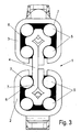
- a modified embodiment of a rolling element cage 10 which has a strip made of a carrier material with higher strength, in which individual recesses 13 are formed at two opposite ends. On each side, three spaced-apart recesses 13 are provided in the longitudinal direction, in each of which a spherical roller body 5 is received. In a plane perpendicular to the longitudinal direction, three rolling elements 5 are provided on the rolling element cage 10. Rolling element holders 11 made of a lubricant-containing material are provided in each recess 13 on the rolling element cage 10. The rolling element holders 11 can be fixed to the recesses 13 of the rolling element cage 10 with a positive, non-positive or material fit.
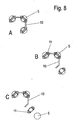
- the spherical rolling elements 5 can first be inserted into receptacles 12 of the rolling element holder 11.
- the rolling elements 5 can be fixed there in a latching manner, the rolling element holder 11 being designed in such a way that three receptacles 12 are provided and the rolling element holder 11 is then mounted on the corresponding recesses 13 of the rails of the rolling element cage 10. It is also possible to use more than three rolling elements with one rolling element holder 5, for example, to accommodate six or nine rolling elements 5.
- the rolling elements 5 rest with a contact surface on a lubricant-containing material, so that continuous lubrication takes place when the pull-out guide is used and the rolling elements 5 are moved.
- a guide rail and at least one running rail are first produced by punching and bending a metal sheet.
- one or more porous bodies which form or form at least part of a rolling body cage, are soaked with lubricant.
- the lubricant is then drawn into the porous body and can then be released again later.
- the impregnation process is preferably carried out over a period of between 10 and 30 hours, in particular 20 to 28 hours.
- the guide rail, the rolling element cage and the at least one running rail are then combined to form a pull-out guide, the rolling elements and the running surfaces being lubricated by moving the at least one running rail relative to the guide rail.
- the porous body for the rolling element cage can be produced from plastic by injection molding, in particular using the two-component injection molding process, in order to fix the plastic material to a carrier material at the same time.
Landscapes
- Engineering & Computer Science (AREA)
- General Engineering & Computer Science (AREA)
- Mechanical Engineering (AREA)
- Bearings For Parts Moving Linearly (AREA)
- Rolling Contact Bearings (AREA)
- Drawers Of Furniture (AREA)
Description
- Die vorliegende Erfindung betrifft eine Auszugsführung nach dem Oberbegriff des Anspruches 1.
- Es ist bekannt, dass Auszugsführungen für eine leichtgängige Verfahrbarkeit der verfahrbar gelagerten Schienen geschmiert werden, damit die Wälzkörper entlang der Laufbahnen verbesserte Laufeigenschaften aufweisen und zudem der Korrosionsschutz erhöht ist. Zudem lassen sich über eine Schmierung mit Fett die Laufgeräusche dämpfen. Bei Auszugsführungen tritt allerdings das Problem auf, dass diese nicht abgedichtet sind und es zu Beeinträchtigungen durch eindringende Fremdkörper oder Verschmutzungen kommen kann. Zudem kann die Schmierung ungewollt entfernt werden. Der Auftrag des Fettes erfolgt in der Regel bei der Herstellung, wobei die Dosierung schwierig ist, da ein Großteil des Fettes auf Flächen aufgetragen wird, die nie in Kontakt mit den Wälzkörpern kommen. Dies ist materialintensiv, wobei ein Fettüberschuss auch die Laufgüte und Funktion negativ beeinflussen kann.
- Die
EP 1 589 291 A1 offenbart ein Auszugssystem für ein Haushaltsgerät, bei dem ein Wälzkörperkäfig zwischen zwei Schienen eine Schmierstoffschicht aufweist. Durch die Schmierstoffbeschichtung sollen die die Wälzkörper an dem Wälzkörperkäfig und das Auszugssystem geschmiert werden. - Es ist daher Aufgabe der vorliegenden Erfindung, eine Auszugsführung für Möbel zu schaffen, die eine optimierte Schmierung aufweist.
- Diese Aufgabe wird mit einer Auszugsführung mit den Merkmalen des Anspruches 1 gelöst.
- Erfindungsgemäß wird eine Auszugsführung für Möbel bereitgestellt, bei der die Wälzkörper in einem Wälzkörperkäfig gelagert sind, der zumindest teilweise aus einem schmierstoffhaltigen Material besteht. Dadurch kann die Schmierung der Wälzkörper gezielt dort erfolgen, wo ein Schmierstoffbedarf besteht, nämlich an den bewegten Flächen der Wälzkörper, die dann für eine gewisse Benetzung der Laufflächen an den Schienen sorgen. Es wird vermieden, dass Schmierstoff auf Flächen gelangt, die nicht geschmiert werden müssen. Zudem kann eine exakte Dosierung des Schmierstoffes über eine lange Zeit erfolgen, da das Aufbringen von Schmierstoff nicht nur einmalig bei der Herstellung erfolgt, sondern kontinuierlich während einer Benutzung der Auszugsführung.
- Die thermische Eigenbewegung von Teilchen liegt der Diffusion zugrunde. Teilchen können Atome, Moleküle oder Ladungsträger sein. In dem vorliegenden Fall handelt es sich um Schmierstoff-Moleküle. Ein makroskopischer Stofftransport wird dadurch bewirkt, dass bei ungleichmäßiger Verteilung sich statistisch mehr Teilchen aus dem Bereich hoher Konzentration in den Bereich geringerer Konzentration bewegen als umgekehrt. Damit ist bis zum Konzentrationsausgleich eine Schmierung der Auszugsführung gewährleistet. Den beschriebenen Diffusionsvorgängen können die Fick'schen Gesetze zugrunde gelegt werden.
- Gemäß einer bevorzugten Ausgestaltung der Erfindung gleiten die Wälzkörper an dem schmierstoffhaltigen Material mit einer Kontaktfläche entlang. Dadurch kann die Kontaktfläche der Wälzkörper mit Schmierstoff benetzt werden, wobei die Wälzkörper dann für eine Verteilung auf die Laufbahnen sorgen. Das schmierstoffhaltige Material kann für einen langen Zeitraum die Wälzkörper schmieren, da der in dem Material enthaltene Schmierstoff an die Oberfläche diffundiert und insofern bei jeder Bewegung der Wälzkörper ein geringer Anteil des Schmierstoffes auf den Wälzkörper übertragen wird. Diese gezielte Schmierung der Wälzkörper führt zu einem optimalen Schmierverhalten. Insbesondere können auch niedrigviskose Schmierstoffe eingesetzt werden, z.B. Öle, die bei einer einmaligen Schmierung bei der Herstellung der Ausziehführung nicht eingesetzt werden können.
- Durch eine geringe Viskosität des Schmierstoffes kann ein großer Temperaturbereich für den Einsatz der Auszugsführungen abgedeckt werden. Somit können in Tiefkühlgeräten die gleichen Auszugsführungen wie in Backöfen eingesetzt werden. Durch die Einlagerung des Schmierstoffes in das schmierstoffhaltige Material tritt nach der Nutzung von Backofenfunktionen wie z.B. der Pyrolysefunktion wieder neuer Schmierstoff durch Diffusion an die Kontaktfläche zu dem Wälzkörper und bewirkt somit seine Schmierung. Der Schmierstoff ist daher vorzugsweise in einem Bereich von über 200°C, insbesondere auch in einem Bereich von über 400°C einsetzbar. Im Tiefkühlbereich ist der Schmierstoff vorzugsweise in einem Bereich unter -15°C einsetzbar, insbesondere auch in einem Bereich unter -40°C einsetzbar.
- Als schmierstoffhaltiges Material ist auch eine Substanz wie z.B. ein Wachs denkbar, die den Schmierstoff nach und nach freisetzt.
- In einer Ausgestaltung ist das schmierstoffhaltige Material ein poröser Körper aus Sintermaterial oder Kunststoff, in dem Öl als Schmierstoff eingelagert ist. Das eingelagerte Öl kann durch Kapillare oder extra eingerichtete Kanäle nachfließen. Der Körper kann nach Art eines Schwammes Schmierstoff aufnehmen und dann bei Betätigung der Auszugsführung nach und nach wieder abgeben.
- Als Trägermaterialien für den Wälzkörperkäfig können alle Materialien genutzt werden, die über eine höhere Festigkeit als das schmierstoffhaltige Material verfügen. Sie müssen den Belastungen bei der Verwendung der Auszugsführung standhalten.
- In der erfindungsgemäßen Ausgestaltung weist der Wälzkörperkäfig eine Vielzahl von Taschen auf, in die jeweils ein Wälzkörperhalter aus schmierstoffhaltigem Material eingefügt ist. In diesem Wälzkörperhalter ist mindestens ein Wälzkörper drehbar eingelagert. Der Wälzkörperhalter kann dabei form-, kraft oder stoffschlüssig an dem Wälzkörperkäfig festgelegt sein, wobei vorzugsweise an einem Wälzkörperhalter mehrere Wälzkörper eingelagert sind.
- Bei einem Verfahren zur Herstellung einer Auszugsführung werden zunächst eine Führungsschiene und mindestens eine Laufschiene hergestellt. Ferner wird mindestens ein poröser Körper, der zumindest einen Teil eines Wälzkörperkäfigs bildet mit Schmierstoff getränkt. Anschließend wird die Führungsschiene, der Wälzkörperkäfig und die mindestens eine Laufschiene zu einer Auszugsführung zusammengesetzt, wobei ein Schmieren der Wälzkörper und der Laufflächen durch Bewegen der mindestens einen Laufschiene relativ zu der Führungsschiene erfolgt. Ergänzend kann die Auszugsführung mit einer auszugsverlängernden Mittelschiene ausgestattet sein, um einen Vollauszug zu realisieren. Diese Mittelschiene wird dann zwischen Führungsschiene und Laufschiene angeordnet.
- Zur Beschleunigung der Sättigung des schmierstoffhaltigen Materials mit Schmierstoff kann ein Hochdruck-Verfahren wie z.B. eine Kesseldruckimprägnierung eingesetzt werden. Hierbei wird der Schmierstoff bei Drücken bis zu 15 bar in das poröse Material gepresst um das schmierstoffhaltige Material zu erhalten.
- Durch jede Betätigung der Auszugsführung wird eine Schmierung der Auszugsführung ausgelöst. Durch die Bewegung der Wälzkörper bzw. der Auszugsführung wird Schmierstoff in die Laufbahnen der Auszugsführung übertragen. Durch die Übertragung von Schmierstoff an der Kontaktfläche schmierstoffhaltiges Material zum Wälzköper bzw. zur Laufbahn der Auszugsführung sinkt die Schmierstoffkonzentration in der Nähe der Kontaktfläche im schmierstoffhaltigen Material. Durch weiter vorne beschriebene Diffusionsvorgänge erfolgt über einen gewissen Zeitraum ein Schmierstoff-Konzentrationsausgleich im schmierstoffhaltigen Material. Durch jede Betätigung der Auszugsführung werden diese Vorgänge erneut ausgelöst.
- Vorzugsweise umfasst der Wälzkörperkäfig ein leistenförmiges Trägermaterial, an dem ein poröser Körper beschichtet oder mechanisch festgelegt wird. Dies ermöglicht eine Herstellung der Auszugsführung mit einer geringen Masse, insbesondere wenn als Trägermaterial ein Kunststoff eingesetzt wird. Dabei kann das Trägermaterial an gegenüberliegenden Endseiten mit einem porösen Körper beschichtet werden um an den porösen Körpern Taschen zur Aufnahme der Wälzkörper auszubilden.
- Alternativ ist eine Fertigung der porösen Körper als Einzelkomponenten aus keramischen oder metallischen Werkstoffen denkbar.
- Die Erfindung wird nachfolgend anhand eines Ausführungsbeispieles mit Bezug auf die beigefügten Zeichnungen näher erläutert. Es zeigen:
- Figuren 1 - 3
- mehrere Ansichten eines Ausführungsbeispieles einer Auszugsführung; und
- Figuren 4 - 8
- mehrere Ansichten eines Ausführungsbeispieles eines Wälzkörperkäfigs einer erfindungsgemäßen Auszugsführung.
- Eine Auszugsführung 1 umfasst eine an einem Möbelkorpus montierbare Führungsschiene 2 und eine Laufschiene 3, an der ein Schubkasten oder anderes Schubelement montiert werden kann. Die Laufschiene 3 ist über Wälzkörper an einer Mittelschiene 4 gelagert, die wiederum über Wälzkörper 5 an der Führungsschiene 2 verfahrbar gelagert ist. Es ist auch möglich, an der Führungsschiene 2 die Laufschiene 3 direkt über Wälzkörper 5 ohne eine Mittelschiene 4 zu lagern.
- Bei der Auszugsführung 1 sind die Wälzkörper 5 zwischen Führungsschiene 2 und Mittelschiene 4 sowie der Mittelschiene 4 und der Laufschiene 3 in einem Wälzkörperkäfig 6 gelagert, der einstückig aus einem schmierstoffhaltigen Material hergestellt ist. Der Wälzkörperkäfig 6 ist aus einem porösen Körper aus Sintermaterial oder Kunststoff gebildet, in dem Öl als Schmierstoff eingelagert ist. Dabei sind die Wälzkörper 5 durch das schmierstoffhaltige Material umspritzt.
- Der Wälzkörperkäfig 6 füllt somit den Innenraum zwischen der Führungsschiene 2 und der Mittelschiene 4 sowie der Mittelschiene 4 und der Laufschiene 3 weitgehend aus, so dass die Wälzkörper 5 vor Verschmutzungen geschützt angeordnet sind. Zudem kann der Schmierstoff durch Kapillaren oder entsprechende Kanäle in dem Wälzkörperkäfig 6 auf die Kontaktflächen der Wälzkörper 5 gelangen, die dann den Schmierstoff auf die Laufbahnen 7 verteilen. Bei jeder Bewegung der Auszugsführung 1 werden die Wälzkörper 5 gedreht, so dass die Kontaktflächen der Wälzkörper 5, die an dem Wälzkörperkäfig 6 anliegen, geringfügig mit Schmierstoff benetzt werden. Dadurch erfolgt während der gesamten Lebensdauer der Auszugsführung 1 kontinuierlich eine Schmierung, die über einen sehr langen Zeitraum aufrecht erhalten werden kann.
- In den
Figuren 4 bis 8 ist eine modifizierte Ausführungsform eines Wälzkörperkäfigs 10 gezeigt, der eine Leiste aus einem Trägermaterial mit höherer Festigkeit aufweist, in der einzelne Aussparungen 13 an zwei gegenüberliegenden Enden ausgebildet sind. Auf jeder Seite sind in Längsrichtung drei voneinander beabstandete Aussparungen 13 vorgesehen, in denen jeweils ein kugelförmiger Wälzkörper 5 aufgenommen ist. In einer Ebene senkrecht zur Längsrichtung sind jeweils drei Wälzkörper 5 an dem Wälzkörperkäfig 10 vorgesehen. In jeder Aussparung 13 sind an dem Wälzkörperkäfig 10 Wälzkörperhalter 11 aus einem schmierstoffhaltigen Material vorgesehen. Die Wälzkörperhalter 11 können an den Aussparungen 13 des Wälzkörperkäfigs 10 form-, kraft- oder stoffschlüssig festgelegt sein. Wie in denFiguren 7 sowie8A bis 8C gezeigt ist, können die kugelförmigen Wälzkörper 5 zunächst in Aufnahmen 12 der Wälzkörperhalter 11 eingefügt werden. Dort können die Wälzkörper 5 rastend festgelegt sein, wobei der Wälzkörperhalter 11 so ausgebildet ist, dass drei Aufnahmen 12 vorgesehen sind und der Wälzkörperhalter 11 dann an den entsprechenden Aussparungen 13 der Schienen des Wälzkörperkäfigs 10 montiert wird. Es ist auch möglich, mit einem Wälzkörperhalter mehr als drei Wälzkörper 5, beispielsweise sechs oder neun Wälzkörper 5 aufzunehmen. - Auch bei diesem Ausführungsbeispiel liegen die Wälzkörper 5 mit einer Kontaktfläche an einem schmierstoffhaltigen Material an, so dass bei der Benutzung der Auszugsführung und Bewegung der Wälzkörper 5 eine kontinuierliche Schmierung erfolgt.
- Bei einem Verfahren zur Herstellung einer Auszugsführung werden zunächst eine Führungsschiene und mindestens eine Laufschiene durch Stanzen und Biegen eines Metallbleches hergestellt. Zudem werden ein oder mehrere poröse Körper, der oder die zumindest einen Teil eines Wälzkörperkäfigs bildet bzw. bilden, mit Schmierstoff getränkt. Der Schmierstoff zieht dann jeweils in den porösen Körper ein und kann dann später wieder abgegeben werden. Der Tränkvorgang wird vorzugsweise in einem Zeitraum zwischen 10 und 30 Stunden, insbesondere 20 bis 28 Stunden durchgeführt. Anschließend werden die Führungsschiene, der Wälzkörperkäfigs und die mindestens eine Laufschiene zu einer Auszugsführung zusammengesetzt, wobei ein Schmieren der Wälzkörper und der Laufflächen durch Bewegen der mindestens einen Laufschiene relativ zu der Führungsschiene erfolgt.
- Der poröse Körper für den Wälzkörperkäfig kann dabei aus Kunststoff durch Spritzguss hergestellt werden, insbesondere im zwei Komponenten Spritzgussverfahren, um das Kunststoffmaterial gleichzeitig an einem Trägermaterial festzulegen.
-
- 1
- Auszugsführung
- 2
- Führungsschiene
- 3
- Laufschiene
- 4
- Mittelschiene
- 5
- Wälzkörper
- 6
- Wälzkörperkäfig
- 7
- Laufbahnen
- 10
- Wälzkörperkäfig
- 11
- Wälzkörperhalter
- 12
- Aufnahmen
- 13
- Aussparung
Claims (5)
- Auszugsführung (1) für Möbel, mit einer an einem Möbelkorpus montierbaren Führungsschiene (2) und mindestens einer über Wälzkörper (5) an der Führungsschiene (2) verfahrbar gelagerten Laufschiene (3, 4), wobei die Laufschiene (3) über Wälzkörper (5) an einer Mittelschiene (4) gelagert ist, die wiederum über Wälzkörper (5) an der Führungsschiene (2) verfahrbar gelagert ist, wobei die Wälzkörper (5) in einem Wälzkörperkäfig (10) gelagert sind, der zumindest teilweise aus einem schmierstoffhaltigen Material besteht, dadurch gekennzeichnet, dass der Wälzkörperkäfig (10) eine Vielzahl von Taschen (13) aufweist, in die jeweils ein Wälzkörperhalter (11) aus schmierstoffhaltigem Material mit einem Wälzkörper (5) eingelagert ist.
- Auszugsführung nach Anspruch 1, dadurch gekennzeichnet, dass die Wälzkörper (5) an dem schmierstoffhaltigen Material mit einer Kontaktfläche entlang gleiten.
- Auszugsführung nach Anspruch 2, dadurch gekennzeichnet, dass über das schmierstoffhaltige Material die Wälzkörper bei einer Bewegung der Auszugsführung (1) an der Kontaktfläche benetzbar sind.
- Auszugsführung nach einem der Ansprüche 1 bis 3, dadurch gekennzeichnet, dass das schmierstoffhaltige Material ein poröser Körper (11) aus Sintermaterial oder Kunststoff ist, in dem Öl als Schmierstoff eingelagert ist.
- Auszugsführung nach Anspruch 1, dadurch gekennzeichnet, dass der Wälzkörperhalter (11) form-, kraft-, und / öder stoffschlüssig an dem Wälzkörperkäfig (10) festgelegt ist.
Priority Applications (1)
| Application Number | Priority Date | Filing Date | Title |
|---|---|---|---|
| PL13152813T PL2586333T5 (pl) | 2008-10-28 | 2009-10-16 | Prowadnica wysuwna |
Applications Claiming Priority (3)
| Application Number | Priority Date | Filing Date | Title |
|---|---|---|---|
| DE102008053504.4A DE102008053504B4 (de) | 2008-10-28 | 2008-10-28 | Auszugsführung für Möbel |
| EP09737406.0A EP2341797B1 (de) | 2008-10-28 | 2009-10-16 | Auszugsführung für möbel und verfahren zur herstellung einer auszugsführung |
| PCT/EP2009/063527 WO2010049283A1 (de) | 2008-10-28 | 2009-10-16 | Auszugsführung für möbel und verfahren zur herstellung einer auszugsführung |
Related Parent Applications (3)
| Application Number | Title | Priority Date | Filing Date |
|---|---|---|---|
| EP09737406.0 Division | 2009-10-16 | ||
| EP09737406.0A Division EP2341797B1 (de) | 2008-10-28 | 2009-10-16 | Auszugsführung für möbel und verfahren zur herstellung einer auszugsführung |
| EP09737406.0A Division-Into EP2341797B1 (de) | 2008-10-28 | 2009-10-16 | Auszugsführung für möbel und verfahren zur herstellung einer auszugsführung |
Publications (3)
| Publication Number | Publication Date |
|---|---|
| EP2586333A1 EP2586333A1 (de) | 2013-05-01 |
| EP2586333B1 EP2586333B1 (de) | 2014-12-10 |
| EP2586333B2 true EP2586333B2 (de) | 2021-06-02 |
Family
ID=41522390
Family Applications (2)
| Application Number | Title | Priority Date | Filing Date |
|---|---|---|---|
| EP13152813.5A Active EP2586333B2 (de) | 2008-10-28 | 2009-10-16 | Auszugsführung |
| EP09737406.0A Active EP2341797B1 (de) | 2008-10-28 | 2009-10-16 | Auszugsführung für möbel und verfahren zur herstellung einer auszugsführung |
Family Applications After (1)
| Application Number | Title | Priority Date | Filing Date |
|---|---|---|---|
| EP09737406.0A Active EP2341797B1 (de) | 2008-10-28 | 2009-10-16 | Auszugsführung für möbel und verfahren zur herstellung einer auszugsführung |
Country Status (8)
| Country | Link |
|---|---|
| US (1) | US20110194791A1 (de) |
| EP (2) | EP2586333B2 (de) |
| KR (2) | KR20160032258A (de) |
| CN (1) | CN102176846B (de) |
| DE (2) | DE102008053504B4 (de) |
| ES (2) | ES2571038T3 (de) |
| PL (2) | PL2341797T3 (de) |
| WO (1) | WO2010049283A1 (de) |
Families Citing this family (20)
| Publication number | Priority date | Publication date | Assignee | Title |
|---|---|---|---|---|
| GB201014390D0 (en) * | 2010-08-27 | 2010-10-13 | Accuride Int Ltd | Improvements in sliding supports and bearing ball retainers |
| DE102010041516A1 (de) * | 2010-09-28 | 2012-03-29 | BSH Bosch und Siemens Hausgeräte GmbH | Auszugsvorrichtung für zumindest einen Gargutträger eines Hausgeräts sowie Hausgerät mit einer derartigen Auszugsvorrichtung |
| DE102010061541A1 (de) * | 2010-12-23 | 2012-06-28 | Paul Hettich Gmbh & Co. Kg | Auszugsführung |
| DE102011120736B4 (de) | 2011-02-01 | 2021-08-12 | Laag S.R.L. | Auszugsführung für einen Backofen oder für eine Spülmaschine |
| CN103016521B (zh) * | 2011-09-23 | 2015-04-29 | 上银科技股份有限公司 | 有限行程的线性滑轨 |
| CN102512005A (zh) * | 2011-11-15 | 2012-06-27 | 雅固拉国际精密工业(苏州)有限公司 | 一种八排滚珠滑道装置 |
| DE102012106751B4 (de) * | 2012-07-25 | 2026-03-19 | Paul Hettich Gmbh & Co. Kg | Auszugsführung für relativ zueinander bewegbare Möbelteile |
| DE102012218006B4 (de) * | 2012-10-02 | 2024-07-25 | BSH Hausgeräte GmbH | Haushaltsgerät |
| DE102012218007A1 (de) * | 2012-10-02 | 2014-04-03 | BSH Bosch und Siemens Hausgeräte GmbH | Haushaltsgerät |
| US9651088B2 (en) * | 2013-06-11 | 2017-05-16 | Yoon Sig PARK | Ball retainer, slide apparatus comprising same and mold for manufacturing same |
| JP2015090187A (ja) * | 2013-11-06 | 2015-05-11 | 日本精工株式会社 | 転がり軸受案内装置 |
| DE102014225890A1 (de) * | 2014-12-15 | 2016-06-16 | BSH Hausgeräte GmbH | Auszugsystem und Haushaltsgargerät |
| US10420421B2 (en) | 2015-04-13 | 2019-09-24 | Segos Co., Ltd. | Slide unit for drawer |
| DE102016120251A1 (de) * | 2016-10-24 | 2018-04-26 | Paul Hettich Gmbh & Co. Kg | Auszugsführung und Verfahren zum Schmieren von Laufbahnen für Wälzkörper an Schienen einer Auszugsführung |
| CN107191481A (zh) * | 2017-08-04 | 2017-09-22 | 苏州弗士曼精密机械有限公司 | 一种滚珠花键 |
| DE102017130108A1 (de) * | 2017-12-15 | 2019-06-19 | Accuride International Gmbh | Teleskopschiene |
| KR20190090981A (ko) * | 2018-01-26 | 2019-08-05 | 삼성전자주식회사 | 가이드 레일과, 그것을 구비하는 수납장치 및 냉장고 |
| DE102020105225A1 (de) * | 2020-02-27 | 2021-09-02 | Paul Hettich Gmbh & Co. Kg | Auszugsführung |
| DE102023127183A1 (de) * | 2023-10-05 | 2025-04-10 | Grass Gmbh | Vorrichtung zur Führung eines beweglichen Möbelteils |
| CN120552713B (zh) * | 2025-07-30 | 2025-10-10 | 浙江奥捷汽车零部件有限公司 | 一种高载低阻腿托滑轨及汽车腿托 |
Citations (1)
| Publication number | Priority date | Publication date | Assignee | Title |
|---|---|---|---|---|
| DE3881901T2 (de) † | 1987-01-12 | 1993-12-16 | Matsushita Electric Ind Co Ltd | Lager mit Trockenschmierung. |
Family Cites Families (27)
| Publication number | Priority date | Publication date | Assignee | Title |
|---|---|---|---|---|
| GB190825276A (en) * | 1908-05-09 | 1909-06-03 | Roberto Incerti & Co | Improvements in and relating to Ball Bearings |
| GB580039A (en) * | 1945-07-31 | 1946-08-23 | Fischer Bearings Company Ltd | Improvements relating to cages for ball and roller bearings |
| US2569531A (en) * | 1947-02-04 | 1951-10-02 | Gen Motors Corp | Ball-bearing structure |
| US2822232A (en) * | 1954-03-05 | 1958-02-04 | Republic Steel Corp | Slide suspension for drawers |
| US2944865A (en) * | 1957-11-16 | 1960-07-12 | Happich G M B H Fa Geb | Ash-trays for vehicles |
| US3966273A (en) * | 1974-09-13 | 1976-06-29 | Hagen Magnus F | Synchronized and precision sequencing of ball retainer relationship to the inner and outer slide members |
| DE2838330A1 (de) * | 1978-08-31 | 1980-03-20 | Betzing Rudolf | Waelzlager mit die waelzkoerper fuehrenden elementen |
| JPS5979628U (ja) * | 1982-11-20 | 1984-05-29 | エヌエスケ−・トリントン株式会社 | 保持具付転動体 |
| US4654940A (en) * | 1984-11-26 | 1987-04-07 | Nippon Thompson Co., Ltd. | Rolling bearing made by thin steel plates for providing a rectilinear movement |
| DE3446328A1 (de) * | 1984-12-19 | 1986-07-10 | Anschuetz & Co Gmbh | Mit einer umlaufschmierung ausgeruestetes lager |
| IT1243108B (it) | 1990-01-24 | 1994-05-24 | Ronda Spa | Struttura di supporto scorrevole per cassetti, particolarmente per frigoriferi industriali |
| DE4024392A1 (de) * | 1990-08-01 | 1992-02-06 | Suspa Compart Ag | Verfahren zum herstellen einer gleitflaeche an einer aus kunststoff bestehenden fuehrungsbuechse fuer eine hoehenverstellbare stuhlsaeule |
| US5230570A (en) * | 1992-05-19 | 1993-07-27 | United Technologies Corporation | High performance rolling element bearing |
| IT1267041B1 (it) * | 1993-05-14 | 1997-01-24 | Compagnucci Spa | Guida ad aste telescopiche per componenti estraibili di mobili, formata da profili tubolari estrusi in alluminio |
| JPH0976371A (ja) * | 1995-09-12 | 1997-03-25 | Mitsubishi Electric Corp | 多孔質プラスチック軸受およびその製造方法 |
| JP3016735B2 (ja) * | 1996-10-01 | 2000-03-06 | 昌 松井 | 高速回転機器の転がり軸受装置 |
| NL1009410C2 (nl) * | 1998-06-15 | 1999-12-16 | Skf Eng & Res Centre Bv | Smeersysteem. |
| US6569816B2 (en) * | 2000-08-18 | 2003-05-27 | Ntn Corporation | Composition having lubricity and product comprising the composition |
| JP2002187773A (ja) * | 2000-12-15 | 2002-07-05 | Minebea Co Ltd | ベアリングリテーナ用材料 |
| DE10338899B3 (de) * | 2003-08-23 | 2005-01-27 | Lorenz, Gerhard, Dipl.-Ing. | Schmierstoff-Speicherelement für wartungsfreie Gleitlager, Gleitschienen u. dgl. |
| DE102004019104A1 (de) * | 2004-04-20 | 2005-11-24 | BSH Bosch und Siemens Hausgeräte GmbH | Auszugssystem für ein Haushaltsgerät |
| JP4541765B2 (ja) * | 2004-06-07 | 2010-09-08 | Ntn株式会社 | 転がり軸受用保持器および転がり軸受 |
| FR2898168B1 (fr) * | 2006-03-06 | 2009-03-06 | Snr Roulements Sa | Procede de lubrification au moyen d'une matrice poreuse comprenant un lubrifiant, roulement et dispositif de transmission de couple ainsi lubrifies |
| JP2008008475A (ja) * | 2006-06-30 | 2008-01-17 | Ntn Corp | 摺動式等速自在継手 |
| DE102006030228A1 (de) * | 2006-06-30 | 2008-01-03 | BSH Bosch und Siemens Hausgeräte GmbH | Haushaltsgreät und Auszugssystem für ein Haushaltsgerät |
| DE102006033124A1 (de) * | 2006-07-18 | 2008-01-24 | Schaeffler Kg | Wälzlager |
| FR2912479B1 (fr) * | 2007-02-09 | 2009-05-08 | Snr Roulements Sa | Cage de retention a reserve de lubrifiant solide comprenant un espace dans les logements de retention |
-
2008
- 2008-10-28 DE DE102008053504.4A patent/DE102008053504B4/de active Active
-
2009
- 2009-10-16 ES ES09737406T patent/ES2571038T3/es active Active
- 2009-10-16 EP EP13152813.5A patent/EP2586333B2/de active Active
- 2009-10-16 DE DE202009018812U patent/DE202009018812U1/de not_active Expired - Lifetime
- 2009-10-16 WO PCT/EP2009/063527 patent/WO2010049283A1/de not_active Ceased
- 2009-10-16 PL PL09737406T patent/PL2341797T3/pl unknown
- 2009-10-16 US US13/120,926 patent/US20110194791A1/en not_active Abandoned
- 2009-10-16 KR KR1020167005979A patent/KR20160032258A/ko not_active Ceased
- 2009-10-16 CN CN2009801397913A patent/CN102176846B/zh active Active
- 2009-10-16 EP EP09737406.0A patent/EP2341797B1/de active Active
- 2009-10-16 ES ES13152813.5T patent/ES2532234T3/es active Active
- 2009-10-16 PL PL13152813T patent/PL2586333T5/pl unknown
- 2009-10-16 KR KR1020117011921A patent/KR20110087304A/ko not_active Ceased
Patent Citations (1)
| Publication number | Priority date | Publication date | Assignee | Title |
|---|---|---|---|---|
| DE3881901T2 (de) † | 1987-01-12 | 1993-12-16 | Matsushita Electric Ind Co Ltd | Lager mit Trockenschmierung. |
Also Published As
| Publication number | Publication date |
|---|---|
| US20110194791A1 (en) | 2011-08-11 |
| EP2586333B1 (de) | 2014-12-10 |
| CN102176846A (zh) | 2011-09-07 |
| PL2586333T3 (pl) | 2015-05-29 |
| EP2586333A1 (de) | 2013-05-01 |
| DE102008053504B4 (de) | 2023-01-26 |
| EP2341797A1 (de) | 2011-07-13 |
| DE102008053504A1 (de) | 2010-04-29 |
| CN102176846B (zh) | 2013-12-11 |
| EP2341797B1 (de) | 2016-02-10 |
| ES2532234T3 (es) | 2015-03-25 |
| KR20160032258A (ko) | 2016-03-23 |
| DE202009018812U1 (de) | 2013-08-13 |
| PL2586333T5 (pl) | 2021-08-16 |
| WO2010049283A1 (de) | 2010-05-06 |
| KR20110087304A (ko) | 2011-08-02 |
| PL2341797T3 (pl) | 2016-07-29 |
| ES2571038T3 (es) | 2016-05-23 |
Similar Documents
| Publication | Publication Date | Title |
|---|---|---|
| EP2586333B1 (de) | Auszugsführung | |
| EP1589289B1 (de) | Auszugssystem für ein Haushaltsgerät | |
| EP2405786B1 (de) | Auszugsführung | |
| DE202011110428U1 (de) | Verbesserung bei Gleitführungen und Kugelkäfigen | |
| DE8903980U1 (de) | Wälzgelagerte Linearführungseinheit | |
| EP1873460B1 (de) | Haushaltsgerät und Auszugssystem für ein Haushaltsgerät | |
| EP2481990A1 (de) | Auszugsführung für einen Backofen oder für eine Spülmaschine | |
| EP1589291B1 (de) | Auszugssystem für ein Haushaltsgerät | |
| EP1022478A1 (de) | Linearbewegungsführung | |
| CH693461A5 (de) | Linearführung mit zwangsgeführtem Käfig. | |
| CH693366A5 (de) | Linearführung mit Zwangsführung des Käfigs. | |
| EP2342503B1 (de) | Auszugsführung und backofen | |
| WO2018077819A1 (de) | Auszugsführung und verfahren zum schmieren von laufbahnen für wälzkörper an schienen einer auszugsführung | |
| EP1589290B1 (de) | Auszugssystem für ein Haushaltsgerät | |
| DE102009016459A1 (de) | Schmiervorrichtung einer Linearführung und Verfahren zur Befüllung einer Schmiervorrichtung mit einem Schmierstoff | |
| EP2422099B1 (de) | Schmiervorrichtung und verfahren zur schmierung einer linearführung | |
| DE4210060A1 (de) | Waelzlager | |
| DE102005032887B3 (de) | Verfahren zur Herstellung einer Lageranordnung und Lageranordnung | |
| DE102012218006B4 (de) | Haushaltsgerät | |
| DE102017118848A1 (de) | Linearführungswagen für eine Führungsschiene eines Linearwälzlagers sowie Linearwälzlager mit dem Linearführungswagen | |
| DE102010041516A1 (de) | Auszugsvorrichtung für zumindest einen Gargutträger eines Hausgeräts sowie Hausgerät mit einer derartigen Auszugsvorrichtung | |
| DE102013113099B3 (de) | Linearschiene mit einer Schmierstruktur | |
| DE102007050475A1 (de) | Führungswagen für ein Linearwälzlager und Verwendung des Führungswagens | |
| DE10247959A1 (de) | Linear-Schiebeführung insbesondere für zueinander verschiebbare Komponenten von Bürostühlen | |
| DE102016204367A1 (de) | Wälzlagerung mit Schmiermittelversorgung |
Legal Events
| Date | Code | Title | Description |
|---|---|---|---|
| PUAI | Public reference made under article 153(3) epc to a published international application that has entered the european phase |
Free format text: ORIGINAL CODE: 0009012 |
|
| AC | Divisional application: reference to earlier application |
Ref document number: 2341797 Country of ref document: EP Kind code of ref document: P |
|
| AK | Designated contracting states |
Kind code of ref document: A1 Designated state(s): AT BE BG CH CY CZ DE DK EE ES FI FR GB GR HR HU IE IS IT LI LT LU LV MC MK MT NL NO PL PT RO SE SI SK SM TR |
|
| 17P | Request for examination filed |
Effective date: 20130503 |
|
| 17Q | First examination report despatched |
Effective date: 20130724 |
|
| GRAP | Despatch of communication of intention to grant a patent |
Free format text: ORIGINAL CODE: EPIDOSNIGR1 |
|
| INTG | Intention to grant announced |
Effective date: 20140722 |
|
| GRAS | Grant fee paid |
Free format text: ORIGINAL CODE: EPIDOSNIGR3 |
|
| GRAA | (expected) grant |
Free format text: ORIGINAL CODE: 0009210 |
|
| AC | Divisional application: reference to earlier application |
Ref document number: 2341797 Country of ref document: EP Kind code of ref document: P |
|
| AK | Designated contracting states |
Kind code of ref document: B1 Designated state(s): AT BE BG CH CY CZ DE DK EE ES FI FR GB GR HR HU IE IS IT LI LT LU LV MC MK MT NL NO PL PT RO SE SI SK SM TR |
|
| REG | Reference to a national code |
Ref country code: GB Ref legal event code: FG4D Free format text: NOT ENGLISH |
|
| REG | Reference to a national code |
Ref country code: CH Ref legal event code: EP |
|
| REG | Reference to a national code |
Ref country code: IE Ref legal event code: FG4D Free format text: LANGUAGE OF EP DOCUMENT: GERMAN |
|
| REG | Reference to a national code |
Ref country code: AT Ref legal event code: REF Ref document number: 700225 Country of ref document: AT Kind code of ref document: T Effective date: 20150115 |
|
| REG | Reference to a national code |
Ref country code: DE Ref legal event code: R096 Ref document number: 502009010348 Country of ref document: DE Effective date: 20150122 |
|
| REG | Reference to a national code |
Ref country code: ES Ref legal event code: FG2A Ref document number: 2532234 Country of ref document: ES Kind code of ref document: T3 Effective date: 20150325 |
|
| REG | Reference to a national code |
Ref country code: NL Ref legal event code: VDEP Effective date: 20141210 |
|
| REG | Reference to a national code |
Ref country code: NL Ref legal event code: VDEP Effective date: 20141210 |
|
| PG25 | Lapsed in a contracting state [announced via postgrant information from national office to epo] |
Ref country code: FI Free format text: LAPSE BECAUSE OF FAILURE TO SUBMIT A TRANSLATION OF THE DESCRIPTION OR TO PAY THE FEE WITHIN THE PRESCRIBED TIME-LIMIT Effective date: 20141210 Ref country code: NO Free format text: LAPSE BECAUSE OF FAILURE TO SUBMIT A TRANSLATION OF THE DESCRIPTION OR TO PAY THE FEE WITHIN THE PRESCRIBED TIME-LIMIT Effective date: 20150310 Ref country code: LT Free format text: LAPSE BECAUSE OF FAILURE TO SUBMIT A TRANSLATION OF THE DESCRIPTION OR TO PAY THE FEE WITHIN THE PRESCRIBED TIME-LIMIT Effective date: 20141210 |
|
| REG | Reference to a national code |
Ref country code: LT Ref legal event code: MG4D |
|
| PG25 | Lapsed in a contracting state [announced via postgrant information from national office to epo] |
Ref country code: HR Free format text: LAPSE BECAUSE OF FAILURE TO SUBMIT A TRANSLATION OF THE DESCRIPTION OR TO PAY THE FEE WITHIN THE PRESCRIBED TIME-LIMIT Effective date: 20141210 Ref country code: LV Free format text: LAPSE BECAUSE OF FAILURE TO SUBMIT A TRANSLATION OF THE DESCRIPTION OR TO PAY THE FEE WITHIN THE PRESCRIBED TIME-LIMIT Effective date: 20141210 Ref country code: GR Free format text: LAPSE BECAUSE OF FAILURE TO SUBMIT A TRANSLATION OF THE DESCRIPTION OR TO PAY THE FEE WITHIN THE PRESCRIBED TIME-LIMIT Effective date: 20150311 Ref country code: SE Free format text: LAPSE BECAUSE OF FAILURE TO SUBMIT A TRANSLATION OF THE DESCRIPTION OR TO PAY THE FEE WITHIN THE PRESCRIBED TIME-LIMIT Effective date: 20141210 |
|
| REG | Reference to a national code |
Ref country code: PL Ref legal event code: T3 |
|
| PG25 | Lapsed in a contracting state [announced via postgrant information from national office to epo] |
Ref country code: NL Free format text: LAPSE BECAUSE OF FAILURE TO SUBMIT A TRANSLATION OF THE DESCRIPTION OR TO PAY THE FEE WITHIN THE PRESCRIBED TIME-LIMIT Effective date: 20141210 |
|
| PG25 | Lapsed in a contracting state [announced via postgrant information from national office to epo] |
Ref country code: CZ Free format text: LAPSE BECAUSE OF FAILURE TO SUBMIT A TRANSLATION OF THE DESCRIPTION OR TO PAY THE FEE WITHIN THE PRESCRIBED TIME-LIMIT Effective date: 20141210 Ref country code: RO Free format text: LAPSE BECAUSE OF FAILURE TO SUBMIT A TRANSLATION OF THE DESCRIPTION OR TO PAY THE FEE WITHIN THE PRESCRIBED TIME-LIMIT Effective date: 20141210 Ref country code: SK Free format text: LAPSE BECAUSE OF FAILURE TO SUBMIT A TRANSLATION OF THE DESCRIPTION OR TO PAY THE FEE WITHIN THE PRESCRIBED TIME-LIMIT Effective date: 20141210 Ref country code: PT Free format text: LAPSE BECAUSE OF FAILURE TO SUBMIT A TRANSLATION OF THE DESCRIPTION OR TO PAY THE FEE WITHIN THE PRESCRIBED TIME-LIMIT Effective date: 20150410 Ref country code: EE Free format text: LAPSE BECAUSE OF FAILURE TO SUBMIT A TRANSLATION OF THE DESCRIPTION OR TO PAY THE FEE WITHIN THE PRESCRIBED TIME-LIMIT Effective date: 20141210 |
|
| PG25 | Lapsed in a contracting state [announced via postgrant information from national office to epo] |
Ref country code: IS Free format text: LAPSE BECAUSE OF FAILURE TO SUBMIT A TRANSLATION OF THE DESCRIPTION OR TO PAY THE FEE WITHIN THE PRESCRIBED TIME-LIMIT Effective date: 20150410 |
|
| REG | Reference to a national code |
Ref country code: DE Ref legal event code: R026 Ref document number: 502009010348 Country of ref document: DE |
|
| PLBI | Opposition filed |
Free format text: ORIGINAL CODE: 0009260 |
|
| 26 | Opposition filed |
Opponent name: ACCURIDE INTERNATIONAL GMBH Effective date: 20150904 |
|
| PLAX | Notice of opposition and request to file observation + time limit sent |
Free format text: ORIGINAL CODE: EPIDOSNOBS2 |
|
| PG25 | Lapsed in a contracting state [announced via postgrant information from national office to epo] |
Ref country code: DK Free format text: LAPSE BECAUSE OF FAILURE TO SUBMIT A TRANSLATION OF THE DESCRIPTION OR TO PAY THE FEE WITHIN THE PRESCRIBED TIME-LIMIT Effective date: 20141210 |
|
| PLBB | Reply of patent proprietor to notice(s) of opposition received |
Free format text: ORIGINAL CODE: EPIDOSNOBS3 |
|
| PG25 | Lapsed in a contracting state [announced via postgrant information from national office to epo] |
Ref country code: SI Free format text: LAPSE BECAUSE OF FAILURE TO SUBMIT A TRANSLATION OF THE DESCRIPTION OR TO PAY THE FEE WITHIN THE PRESCRIBED TIME-LIMIT Effective date: 20141210 |
|
| PG25 | Lapsed in a contracting state [announced via postgrant information from national office to epo] |
Ref country code: LU Free format text: LAPSE BECAUSE OF FAILURE TO SUBMIT A TRANSLATION OF THE DESCRIPTION OR TO PAY THE FEE WITHIN THE PRESCRIBED TIME-LIMIT Effective date: 20151016 |
|
| REG | Reference to a national code |
Ref country code: CH Ref legal event code: PL |
|
| GBPC | Gb: european patent ceased through non-payment of renewal fee |
Effective date: 20151016 |
|
| PG25 | Lapsed in a contracting state [announced via postgrant information from national office to epo] |
Ref country code: MC Free format text: LAPSE BECAUSE OF FAILURE TO SUBMIT A TRANSLATION OF THE DESCRIPTION OR TO PAY THE FEE WITHIN THE PRESCRIBED TIME-LIMIT Effective date: 20141210 |
|
| REG | Reference to a national code |
Ref country code: IE Ref legal event code: MM4A |
|
| PG25 | Lapsed in a contracting state [announced via postgrant information from national office to epo] |
Ref country code: LI Free format text: LAPSE BECAUSE OF NON-PAYMENT OF DUE FEES Effective date: 20151031 Ref country code: CH Free format text: LAPSE BECAUSE OF NON-PAYMENT OF DUE FEES Effective date: 20151031 Ref country code: GB Free format text: LAPSE BECAUSE OF NON-PAYMENT OF DUE FEES Effective date: 20151016 |
|
| REG | Reference to a national code |
Ref country code: FR Ref legal event code: ST Effective date: 20160630 |
|
| PG25 | Lapsed in a contracting state [announced via postgrant information from national office to epo] |
Ref country code: FR Free format text: LAPSE BECAUSE OF NON-PAYMENT OF DUE FEES Effective date: 20151102 |
|
| PG25 | Lapsed in a contracting state [announced via postgrant information from national office to epo] |
Ref country code: IE Free format text: LAPSE BECAUSE OF NON-PAYMENT OF DUE FEES Effective date: 20151016 |
|
| REG | Reference to a national code |
Ref country code: DE Ref legal event code: R079 Ref document number: 502009010348 Country of ref document: DE Free format text: PREVIOUS MAIN CLASS: A47B0088100000 Ipc: A47B0088493000 |
|
| REG | Reference to a national code |
Ref country code: AT Ref legal event code: MM01 Ref document number: 700225 Country of ref document: AT Kind code of ref document: T Effective date: 20151016 |
|
| PG25 | Lapsed in a contracting state [announced via postgrant information from national office to epo] |
Ref country code: AT Free format text: LAPSE BECAUSE OF NON-PAYMENT OF DUE FEES Effective date: 20151016 |
|
| PG25 | Lapsed in a contracting state [announced via postgrant information from national office to epo] |
Ref country code: HU Free format text: LAPSE BECAUSE OF FAILURE TO SUBMIT A TRANSLATION OF THE DESCRIPTION OR TO PAY THE FEE WITHIN THE PRESCRIBED TIME-LIMIT; INVALID AB INITIO Effective date: 20091016 Ref country code: BG Free format text: LAPSE BECAUSE OF FAILURE TO SUBMIT A TRANSLATION OF THE DESCRIPTION OR TO PAY THE FEE WITHIN THE PRESCRIBED TIME-LIMIT Effective date: 20141210 Ref country code: SM Free format text: LAPSE BECAUSE OF FAILURE TO SUBMIT A TRANSLATION OF THE DESCRIPTION OR TO PAY THE FEE WITHIN THE PRESCRIBED TIME-LIMIT Effective date: 20141210 |
|
| PG25 | Lapsed in a contracting state [announced via postgrant information from national office to epo] |
Ref country code: CY Free format text: LAPSE BECAUSE OF FAILURE TO SUBMIT A TRANSLATION OF THE DESCRIPTION OR TO PAY THE FEE WITHIN THE PRESCRIBED TIME-LIMIT Effective date: 20141210 |
|
| PG25 | Lapsed in a contracting state [announced via postgrant information from national office to epo] |
Ref country code: BE Free format text: LAPSE BECAUSE OF NON-PAYMENT OF DUE FEES Effective date: 20151031 |
|
| PG25 | Lapsed in a contracting state [announced via postgrant information from national office to epo] |
Ref country code: MT Free format text: LAPSE BECAUSE OF FAILURE TO SUBMIT A TRANSLATION OF THE DESCRIPTION OR TO PAY THE FEE WITHIN THE PRESCRIBED TIME-LIMIT Effective date: 20141210 |
|
| APBM | Appeal reference recorded |
Free format text: ORIGINAL CODE: EPIDOSNREFNO |
|
| APBP | Date of receipt of notice of appeal recorded |
Free format text: ORIGINAL CODE: EPIDOSNNOA2O |
|
| APAH | Appeal reference modified |
Free format text: ORIGINAL CODE: EPIDOSCREFNO |
|
| APBQ | Date of receipt of statement of grounds of appeal recorded |
Free format text: ORIGINAL CODE: EPIDOSNNOA3O |
|
| PGFP | Annual fee paid to national office [announced via postgrant information from national office to epo] |
Ref country code: ES Payment date: 20171103 Year of fee payment: 9 Ref country code: IT Payment date: 20171020 Year of fee payment: 9 |
|
| PG25 | Lapsed in a contracting state [announced via postgrant information from national office to epo] |
Ref country code: MK Free format text: LAPSE BECAUSE OF FAILURE TO SUBMIT A TRANSLATION OF THE DESCRIPTION OR TO PAY THE FEE WITHIN THE PRESCRIBED TIME-LIMIT Effective date: 20141210 |
|
| APAH | Appeal reference modified |
Free format text: ORIGINAL CODE: EPIDOSCREFNO |
|
| PG25 | Lapsed in a contracting state [announced via postgrant information from national office to epo] |
Ref country code: IT Free format text: LAPSE BECAUSE OF NON-PAYMENT OF DUE FEES Effective date: 20181016 |
|
| REG | Reference to a national code |
Ref country code: ES Ref legal event code: FD2A Effective date: 20191202 |
|
| APAH | Appeal reference modified |
Free format text: ORIGINAL CODE: EPIDOSCREFNO |
|
| PG25 | Lapsed in a contracting state [announced via postgrant information from national office to epo] |
Ref country code: ES Free format text: LAPSE BECAUSE OF NON-PAYMENT OF DUE FEES Effective date: 20181017 |
|
| APBU | Appeal procedure closed |
Free format text: ORIGINAL CODE: EPIDOSNNOA9O |
|
| PUAH | Patent maintained in amended form |
Free format text: ORIGINAL CODE: 0009272 |
|
| STAA | Information on the status of an ep patent application or granted ep patent |
Free format text: STATUS: PATENT MAINTAINED AS AMENDED |
|
| 27A | Patent maintained in amended form |
Effective date: 20210602 |
|
| AK | Designated contracting states |
Kind code of ref document: B2 Designated state(s): AT BE BG CH CY CZ DE DK EE ES FI FR GB GR HR HU IE IS IT LI LT LU LV MC MK MT NL NO PL PT RO SE SI SK SM TR |
|
| REG | Reference to a national code |
Ref country code: DE Ref legal event code: R102 Ref document number: 502009010348 Country of ref document: DE |
|
| P01 | Opt-out of the competence of the unified patent court (upc) registered |
Effective date: 20230414 |
|
| PGFP | Annual fee paid to national office [announced via postgrant information from national office to epo] |
Ref country code: DE Payment date: 20251020 Year of fee payment: 17 |
|
| PGFP | Annual fee paid to national office [announced via postgrant information from national office to epo] |
Ref country code: TR Payment date: 20251014 Year of fee payment: 17 |
|
| PGFP | Annual fee paid to national office [announced via postgrant information from national office to epo] |
Ref country code: PL Payment date: 20251003 Year of fee payment: 17 |