EP2586357A1 - Drying device for a dishwasher - Google Patents
Drying device for a dishwasher Download PDFInfo
- Publication number
- EP2586357A1 EP2586357A1 EP12190120.1A EP12190120A EP2586357A1 EP 2586357 A1 EP2586357 A1 EP 2586357A1 EP 12190120 A EP12190120 A EP 12190120A EP 2586357 A1 EP2586357 A1 EP 2586357A1
- Authority
- EP
- European Patent Office
- Prior art keywords
- casing
- dishwasher
- tube
- water supply
- water
- Prior art date
- Legal status (The legal status is an assumption and is not a legal conclusion. Google has not performed a legal analysis and makes no representation as to the accuracy of the status listed.)
- Withdrawn
Links
- 238000001035 drying Methods 0.000 title claims abstract description 10
- XLYOFNOQVPJJNP-UHFFFAOYSA-N water Substances O XLYOFNOQVPJJNP-UHFFFAOYSA-N 0.000 claims abstract description 20
- 238000009833 condensation Methods 0.000 claims abstract description 9
- 230000005494 condensation Effects 0.000 claims abstract description 9
- 238000000071 blow moulding Methods 0.000 claims description 2
- 238000001746 injection moulding Methods 0.000 claims description 2
- 238000005406 washing Methods 0.000 description 2
- 239000004743 Polypropylene Substances 0.000 description 1
- WYTGDNHDOZPMIW-RCBQFDQVSA-N alstonine Natural products C1=CC2=C3C=CC=CC3=NC2=C2N1C[C@H]1[C@H](C)OC=C(C(=O)OC)[C@H]1C2 WYTGDNHDOZPMIW-RCBQFDQVSA-N 0.000 description 1
- 230000015572 biosynthetic process Effects 0.000 description 1
- 239000012267 brine Substances 0.000 description 1
- 238000010276 construction Methods 0.000 description 1
- 239000007788 liquid Substances 0.000 description 1
- 238000004519 manufacturing process Methods 0.000 description 1
- 239000000463 material Substances 0.000 description 1
- 239000004033 plastic Substances 0.000 description 1
- -1 polypropylene Polymers 0.000 description 1
- 229920001155 polypropylene Polymers 0.000 description 1
- 230000008929 regeneration Effects 0.000 description 1
- 238000011069 regeneration method Methods 0.000 description 1
- HPALAKNZSZLMCH-UHFFFAOYSA-M sodium;chloride;hydrate Chemical compound O.[Na+].[Cl-] HPALAKNZSZLMCH-UHFFFAOYSA-M 0.000 description 1
- 238000011144 upstream manufacturing Methods 0.000 description 1
Images


Classifications
-
- A—HUMAN NECESSITIES
- A47—FURNITURE; DOMESTIC ARTICLES OR APPLIANCES; COFFEE MILLS; SPICE MILLS; SUCTION CLEANERS IN GENERAL
- A47L—DOMESTIC WASHING OR CLEANING; SUCTION CLEANERS IN GENERAL
- A47L15/00—Washing or rinsing machines for crockery or tableware
- A47L15/42—Details
- A47L15/48—Drying arrangements
- A47L15/483—Drying arrangements by using condensers
-
- A—HUMAN NECESSITIES
- A47—FURNITURE; DOMESTIC ARTICLES OR APPLIANCES; COFFEE MILLS; SPICE MILLS; SUCTION CLEANERS IN GENERAL
- A47L—DOMESTIC WASHING OR CLEANING; SUCTION CLEANERS IN GENERAL
- A47L15/00—Washing or rinsing machines for crockery or tableware
- A47L15/42—Details
- A47L15/4214—Water supply, recirculation or discharge arrangements; Devices therefor
- A47L15/4217—Fittings for water supply, e.g. valves or plumbing means to connect to cold or warm water lines, aquastops
Definitions
- the present invention relates to a drying device for dishwashers.
- a known device of this type comprises a receptacle made of plastic material, typically polypropylene, within which cold water is made to flow so as to cause the vapour formed in the washing chamber to condense on the outer surface of the receptacle.
- the object of the present invention is to provide a drying device which has an increased heat exchange surface while also having a low production cost.
- a drying device for dishwashers comprising a vapour condensation chamber formed within a casing and containing a corrugated tube within which there flows water for causing the condensation of vapour on its outer surface, wherein the aforesaid corrugated tube has a serpentine-shaped portion.
- the corrugated tube which is economical to be produced and which has a high surface area per unit of length, enabling the heat exchange to be increased.
- the tube contains a relatively small quantity of water, which, in the preferred case in which the tube forms a portion of the conduit for supplying water to the dishwasher, can easily be renewed by opening the main filling valve.
- the bends of the serpentine-shaped corrugated tube enable the heat exchange surface per unit of volume of the condensation chamber to be increased considerably, thereby significantly increasing the extent of the change from the vapour state to the liquid state.
- the device according to the invention can be produced in the form of an independent module, which can be mounted on a water supply device of the dishwasher, commonly called an air break, or in the form of an integral part of the air break.
- a further object of the present invention is a dishwasher comprising a drying device of the aforementioned type.
- a drying device for a dishwasher comprising a vapour condensation chamber 10, which is formed within a casing of flattened shape 12 and which contains a corrugated tube 14, is integrated into a water supply device commonly called an "air break" 16.
- the casing of flattened shape 12 forms a prolongation of the casing of the casing of the air break 16, while the corrugated tube 14 forms a portion of a water supply conduit.
- the ends of the tube 14 are fitted on to sleeves 18 which protrude into the casing of the air break 16, in such a way that the tube 14, which includes a serpentine-shaped portion 20 having a plurality of bends and held up by a support 22 within the chamber 10, acts as a connecting link between a first and a second section 24, 26 of the supply conduit, which form part of the air break 16.
- the air break itself has an entirely conventional structure and has an opening 28 which, when mounted at the side of a side wall of the washing chamber of the dishwasher, acts as a passage for the discharge of vapours which are formed during operation; the air break also has further sleeves 30, 32 for conveying water to be softened to a softener (not shown in the figures) and for sending the water required for the formation of a regeneration brine to the softener.
- the vapour entering the chamber 10 comes into contact with the outer surface of the tube 14, which is cold because of the presence of water within it, and the vapour is therefore able to condense.
- the corrugation of the surface of the tube 14 and its serpentine shape provide a large heat exchange surface, thus increasing the amount of condensation.
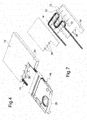
- FIG. 3 to 7 Another embodiment of the device according to the invention is shown in Figures 3 to 7 , in which numbers identical to those used in the preceding figures denote identical or equivalent parts.
- the drying device forms an independent module, which can be associated with a water supply device 16.
- the casing 12 is flat and is substantially rectangular in plan view, with a protuberance 34 at one end of one of the short sides.
- the casing 12 also has a plurality of resilient teeth 36 which are spaced apart, for fastening to the water supply device 16.
- the corrugated tube 14 forms a portion of a water supply conduit, located upstream of an air gap portion 27 formed in the device 16.
- the support 22 of the serpentine portion 20 of the tube 14 is formed by a series of strips offset from each other in two orthogonal directions, with recesses into which corresponding sections of the tube 14 can be fitted.
- the casing 12 ( Figure 6 ) can be made by blow moulding in one piece, into which the tube 14 with its support 22 is subsequently inserted.
- the casing 12 can be made by injection moulding in two pieces which are welded together subsequently.
Landscapes
- Engineering & Computer Science (AREA)
- Water Supply & Treatment (AREA)
- Washing And Drying Of Tableware (AREA)
Applications Claiming Priority (1)
| Application Number | Priority Date | Filing Date | Title |
|---|---|---|---|
| IT000985A ITTO20110985A1 (it) | 2011-10-28 | 2011-10-28 | Dispositivo di asciugatura per lavastoviglie |
Publications (1)
| Publication Number | Publication Date |
|---|---|
| EP2586357A1 true EP2586357A1 (en) | 2013-05-01 |
Family
ID=45757126
Family Applications (1)
| Application Number | Title | Priority Date | Filing Date |
|---|---|---|---|
| EP12190120.1A Withdrawn EP2586357A1 (en) | 2011-10-28 | 2012-10-26 | Drying device for a dishwasher |
Country Status (2)
| Country | Link |
|---|---|
| EP (1) | EP2586357A1 (it) |
| IT (1) | ITTO20110985A1 (it) |
Cited By (1)
| Publication number | Priority date | Publication date | Assignee | Title |
|---|---|---|---|---|
| US10750925B2 (en) | 2018-01-12 | 2020-08-25 | Whirlpool Corporation | Method of operating a dishwasher |
Citations (7)
| Publication number | Priority date | Publication date | Assignee | Title |
|---|---|---|---|---|
| DE1926049A1 (de) * | 1969-05-22 | 1970-11-26 | Kronwitter Geb Staiber | Verfahren zur Reinigung von Geschirr,insbesondere in Haushaltsgeschirrspuelmaschinen |
| US4995454A (en) * | 1989-11-17 | 1991-02-26 | Thompson Donovan S | Heat exchanger with corrugated tubes |
| EP0753282A1 (en) * | 1995-07-14 | 1997-01-15 | TECNOPLASTICA PREALPINA S.p.A. | A device for cooling and condensing the steam released from the washing drum of a dishwasher machine and the like |
| EP0978250A2 (en) * | 1998-08-06 | 2000-02-09 | Bitron S.p.A. | A device for drying the dishes at the end of the washing process of a dishwasher |
| US20050113698A1 (en) * | 2003-11-21 | 2005-05-26 | Kjell Kristoffersen | Ultrasound probe transceiver circuitry |
| EP1825800A2 (de) * | 2006-02-22 | 2007-08-29 | V-Zug AG | Geschirrspüler mit Mitteln zum Abziehen von Feuchte aus dem Bottich |
| DE102007007133A1 (de) * | 2007-02-13 | 2008-08-14 | Meiko Maschinenbau Gmbh & Co. Kg | Frontlader-Geschirrspülmaschine mit Wärmerückgewinnung |
-
2011
- 2011-10-28 IT IT000985A patent/ITTO20110985A1/it unknown
-
2012
- 2012-10-26 EP EP12190120.1A patent/EP2586357A1/en not_active Withdrawn
Patent Citations (7)
| Publication number | Priority date | Publication date | Assignee | Title |
|---|---|---|---|---|
| DE1926049A1 (de) * | 1969-05-22 | 1970-11-26 | Kronwitter Geb Staiber | Verfahren zur Reinigung von Geschirr,insbesondere in Haushaltsgeschirrspuelmaschinen |
| US4995454A (en) * | 1989-11-17 | 1991-02-26 | Thompson Donovan S | Heat exchanger with corrugated tubes |
| EP0753282A1 (en) * | 1995-07-14 | 1997-01-15 | TECNOPLASTICA PREALPINA S.p.A. | A device for cooling and condensing the steam released from the washing drum of a dishwasher machine and the like |
| EP0978250A2 (en) * | 1998-08-06 | 2000-02-09 | Bitron S.p.A. | A device for drying the dishes at the end of the washing process of a dishwasher |
| US20050113698A1 (en) * | 2003-11-21 | 2005-05-26 | Kjell Kristoffersen | Ultrasound probe transceiver circuitry |
| EP1825800A2 (de) * | 2006-02-22 | 2007-08-29 | V-Zug AG | Geschirrspüler mit Mitteln zum Abziehen von Feuchte aus dem Bottich |
| DE102007007133A1 (de) * | 2007-02-13 | 2008-08-14 | Meiko Maschinenbau Gmbh & Co. Kg | Frontlader-Geschirrspülmaschine mit Wärmerückgewinnung |
Cited By (2)
| Publication number | Priority date | Publication date | Assignee | Title |
|---|---|---|---|---|
| US10750925B2 (en) | 2018-01-12 | 2020-08-25 | Whirlpool Corporation | Method of operating a dishwasher |
| US10986977B2 (en) | 2018-01-12 | 2021-04-27 | Whirlpool Corporation | Method of operating a dishwasher |
Also Published As
| Publication number | Publication date |
|---|---|
| ITTO20110985A1 (it) | 2013-04-29 |
Similar Documents
| Publication | Publication Date | Title |
|---|---|---|
| CN107110489B (zh) | 蒸汽发生器 | |
| US7813628B2 (en) | Instantaneous steam boiler | |
| KR101764579B1 (ko) | 라디에이터 및 콘덴서 조립체 | |
| RU2570777C1 (ru) | Смывное устройство для бытового прибора для обработки белья и бытовой прибор с таким устройством | |
| CN107854084B (zh) | 用于水槽洗碗机的呼吸器和水槽洗碗机 | |
| CN206507915U (zh) | 洗碗机的冷凝干燥系统和具有其的洗碗机 | |
| CN104421921B (zh) | 蒸汽发生器及具有它的蒸汽烹饪器具 | |
| EP2586357A1 (en) | Drying device for a dishwasher | |
| GB2532768A (en) | Evaporator arrangement | |
| CN104781464A (zh) | 用于护理洗涤物件的家用器具的冲入组件以及用于护理洗涤物件的家用器具 | |
| EP2586354B1 (en) | Water supply device for a dishwasher | |
| CN114729498B (zh) | 用于蒸汽熨烫设备的板及相应的制造方法 | |
| CN104633913B (zh) | 电热水器 | |
| CN104011283B (zh) | 具有冲入壳和碱液容器的用于护理洗涤物件的家用器具 | |
| CN105088686A (zh) | 洗衣机及其自动投放系统 | |
| US20180008915A1 (en) | Filters for Appliances | |
| KR102748441B1 (ko) | 열교환기 | |
| RU2011108479A (ru) | Пылесос и вставная деталь пылесоса | |
| CN112361310A (zh) | 蒸汽发生器及蒸汽护理工具 | |
| US20180001240A1 (en) | Filters for Non-Plumbed Appliances | |
| CN107995853A (zh) | 用于洗碗机的集成部件 | |
| CN110960171A (zh) | 用于洗碗机的呼吸器和洗碗机 | |
| EP2586356B1 (en) | Water supply device | |
| US20180001239A1 (en) | Filters for Non-Plumbed Appliances | |
| CN104633914B (zh) | 电热水器 |
Legal Events
| Date | Code | Title | Description |
|---|---|---|---|
| PUAI | Public reference made under article 153(3) epc to a published international application that has entered the european phase |
Free format text: ORIGINAL CODE: 0009012 |
|
| AK | Designated contracting states |
Kind code of ref document: A1 Designated state(s): AL AT BE BG CH CY CZ DE DK EE ES FI FR GB GR HR HU IE IS IT LI LT LU LV MC MK MT NL NO PL PT RO RS SE SI SK SM TR |
|
| AX | Request for extension of the european patent |
Extension state: BA ME |
|
| 17P | Request for examination filed |
Effective date: 20131028 |
|
| RBV | Designated contracting states (corrected) |
Designated state(s): AL AT BE BG CH CY CZ DE DK EE ES FI FR GB GR HR HU IE IS IT LI LT LU LV MC MK MT NL NO PL PT RO RS SE SI SK SM TR |
|
| 17Q | First examination report despatched |
Effective date: 20140929 |
|
| STAA | Information on the status of an ep patent application or granted ep patent |
Free format text: STATUS: THE APPLICATION IS DEEMED TO BE WITHDRAWN |
|
| 18D | Application deemed to be withdrawn |
Effective date: 20151121 |