EP2586520A1 - Filtervorrichtung mit festem Chaosdurchflussinduzierer - Google Patents
Filtervorrichtung mit festem Chaosdurchflussinduzierer Download PDFInfo
- Publication number
- EP2586520A1 EP2586520A1 EP12002934.3A EP12002934A EP2586520A1 EP 2586520 A1 EP2586520 A1 EP 2586520A1 EP 12002934 A EP12002934 A EP 12002934A EP 2586520 A1 EP2586520 A1 EP 2586520A1
- Authority
- EP
- European Patent Office
- Prior art keywords
- chaos
- induction unit
- chaos flow
- unit bodies
- filtering apparatus
- Prior art date
- Legal status (The legal status is an assumption and is not a legal conclusion. Google has not performed a legal analysis and makes no representation as to the accuracy of the status listed.)
- Withdrawn
Links
- 238000001914 filtration Methods 0.000 title claims abstract description 74
- 239000000411 inducer Substances 0.000 title abstract description 34
- 239000012528 membrane Substances 0.000 claims abstract description 78
- 238000000926 separation method Methods 0.000 claims abstract description 58
- 230000006698 induction Effects 0.000 claims description 111
- XLYOFNOQVPJJNP-UHFFFAOYSA-N water Substances O XLYOFNOQVPJJNP-UHFFFAOYSA-N 0.000 claims description 57
- 230000001939 inductive effect Effects 0.000 claims description 41
- 230000008093 supporting effect Effects 0.000 claims description 4
- 239000002245 particle Substances 0.000 description 73
- 239000012530 fluid Substances 0.000 description 35
- 238000000034 method Methods 0.000 description 29
- 238000004458 analytical method Methods 0.000 description 27
- 230000008859 change Effects 0.000 description 23
- 238000005516 engineering process Methods 0.000 description 23
- 230000008569 process Effects 0.000 description 17
- 230000000694 effects Effects 0.000 description 16
- 230000000739 chaotic effect Effects 0.000 description 15
- 238000013461 design Methods 0.000 description 14
- 238000012360 testing method Methods 0.000 description 13
- 230000008901 benefit Effects 0.000 description 11
- 230000033001 locomotion Effects 0.000 description 11
- 230000004907 flux Effects 0.000 description 9
- 238000004519 manufacturing process Methods 0.000 description 9
- 238000005406 washing Methods 0.000 description 9
- 239000000356 contaminant Substances 0.000 description 8
- 230000001965 increasing effect Effects 0.000 description 8
- 238000011109 contamination Methods 0.000 description 7
- 235000012206 bottled water Nutrition 0.000 description 6
- 239000003651 drinking water Substances 0.000 description 6
- 230000007423 decrease Effects 0.000 description 5
- 238000009826 distribution Methods 0.000 description 4
- 238000011156 evaluation Methods 0.000 description 4
- 238000005206 flow analysis Methods 0.000 description 4
- 239000011148 porous material Substances 0.000 description 4
- 238000007599 discharging Methods 0.000 description 3
- 238000003780 insertion Methods 0.000 description 3
- 230000037431 insertion Effects 0.000 description 3
- 238000009434 installation Methods 0.000 description 3
- 244000144972 livestock Species 0.000 description 3
- 239000007787 solid Substances 0.000 description 3
- 239000000126 substance Substances 0.000 description 3
- 239000002351 wastewater Substances 0.000 description 3
- 238000005299 abrasion Methods 0.000 description 2
- 230000003247 decreasing effect Effects 0.000 description 2
- 230000006866 deterioration Effects 0.000 description 2
- 230000001976 improved effect Effects 0.000 description 2
- 238000005374 membrane filtration Methods 0.000 description 2
- 238000011160 research Methods 0.000 description 2
- 238000001223 reverse osmosis Methods 0.000 description 2
- 241000894006 Bacteria Species 0.000 description 1
- 241000223935 Cryptosporidium Species 0.000 description 1
- 241000224466 Giardia Species 0.000 description 1
- CBENFWSGALASAD-UHFFFAOYSA-N Ozone Chemical compound [O-][O+]=O CBENFWSGALASAD-UHFFFAOYSA-N 0.000 description 1
- XLYOFNOQVPJJNP-PWCQTSIFSA-N Tritiated water Chemical compound [3H]O[3H] XLYOFNOQVPJJNP-PWCQTSIFSA-N 0.000 description 1
- 238000009825 accumulation Methods 0.000 description 1
- 230000000903 blocking effect Effects 0.000 description 1
- 238000004140 cleaning Methods 0.000 description 1
- 239000003086 colorant Substances 0.000 description 1
- 238000010612 desalination reaction Methods 0.000 description 1
- 238000011161 development Methods 0.000 description 1
- 230000018109 developmental process Effects 0.000 description 1
- 239000006185 dispersion Substances 0.000 description 1
- 239000010840 domestic wastewater Substances 0.000 description 1
- 238000005183 dynamical system Methods 0.000 description 1
- 238000005265 energy consumption Methods 0.000 description 1
- 230000002708 enhancing effect Effects 0.000 description 1
- 239000000383 hazardous chemical Substances 0.000 description 1
- 239000010842 industrial wastewater Substances 0.000 description 1
- 235000000396 iron Nutrition 0.000 description 1
- 238000003475 lamination Methods 0.000 description 1
- 238000012986 modification Methods 0.000 description 1
- 230000004048 modification Effects 0.000 description 1
- 238000005457 optimization Methods 0.000 description 1
- 230000002265 prevention Effects 0.000 description 1
- 230000001737 promoting effect Effects 0.000 description 1
- 238000011002 quantification Methods 0.000 description 1
- 238000011158 quantitative evaluation Methods 0.000 description 1
- 239000004576 sand Substances 0.000 description 1
- 239000013535 sea water Substances 0.000 description 1
- 230000035939 shock Effects 0.000 description 1
- 238000004065 wastewater treatment Methods 0.000 description 1
Images







Classifications
-
- B—PERFORMING OPERATIONS; TRANSPORTING
- B01—PHYSICAL OR CHEMICAL PROCESSES OR APPARATUS IN GENERAL
- B01D—SEPARATION
- B01D65/00—Accessories or auxiliary operations, in general, for separation processes or apparatus using semi-permeable membranes
- B01D65/08—Prevention of membrane fouling or of concentration polarisation
-
- B—PERFORMING OPERATIONS; TRANSPORTING
- B01—PHYSICAL OR CHEMICAL PROCESSES OR APPARATUS IN GENERAL
- B01D—SEPARATION
- B01D35/00—Filtering devices having features not specifically covered by groups B01D24/00 - B01D33/00, or for applications not specifically covered by groups B01D24/00 - B01D33/00; Auxiliary devices for filtration; Filter housing constructions
-
- B—PERFORMING OPERATIONS; TRANSPORTING
- B01—PHYSICAL OR CHEMICAL PROCESSES OR APPARATUS IN GENERAL
- B01D—SEPARATION
- B01D63/00—Apparatus in general for separation processes using semi-permeable membranes
- B01D63/06—Tubular membrane modules
-
- C—CHEMISTRY; METALLURGY
- C02—TREATMENT OF WATER, WASTE WATER, SEWAGE, OR SLUDGE
- C02F—TREATMENT OF WATER, WASTE WATER, SEWAGE, OR SLUDGE
- C02F1/00—Treatment of water, waste water, or sewage
- C02F1/44—Treatment of water, waste water, or sewage by dialysis, osmosis or reverse osmosis
-
- B—PERFORMING OPERATIONS; TRANSPORTING
- B01—PHYSICAL OR CHEMICAL PROCESSES OR APPARATUS IN GENERAL
- B01D—SEPARATION
- B01D2321/00—Details relating to membrane cleaning, regeneration, sterilization or to the prevention of fouling
- B01D2321/20—By influencing the flow
- B01D2321/2008—By influencing the flow statically
- B01D2321/2016—Static mixers; Turbulence generators
Definitions
- the present invention relates to a filtering apparatus having a fixed-type chaos-flow inducer.
- Filtration technology is widely used from potable water production and waste water treatment. Especially the potable water contamination accidents occurred in United States in 1993 and in Japan in 1996 became the decisive opportunity for the introduction of membrane process in the potable water treatment process. At present, the filtration technology utilizing membrane is being expanded further.
- a membrane is a film with fine pores smaller than few ⁇ ms.
- the membrane removes contaminants by Sieve effect, in which the membrane passes particles smaller than the pore on the surface and blocks the particles bigger than the pore. It is an environment-friendly treatment process because safe potable water is produced by almost perfectly removing the hazardous substances in water such as organic/inorganic substances, crypto-parasites and bacteria. The process also uses fewer amounts of chemicals than the existing water treatment processes.
- the precision filter membrane and the ultra filter membrane are used in potable water production and treatment of domestic/industrial wastewater.
- the nano filter membrane and the reverse-osmosis filter membrane are used to produce pure water, which contains negligible amount of contaminants.
- the membrane is used since it is easy to secure the fixed quality of water. Especially in Korea, there are wide variations in the quality of raw water in the four seasons. In spring and fall, raw water gets impact of tide. In summer, water has high degree of muddiness. In winter, water temperature is very low. Therefore, it is almost impossible to secure constant quality of water through existing sand filtering methods. There are other advance methods utilizing UV or ozone; however, they also have their own issues. Especially the recent issues of protozoa such as Giardia and Cryptosporidium cannot be resolved by existing methods and it is difficult to secure stable water quality. The membrane solves most of these issues and it is possible to produce fixed quality of water without getting serious impact from the raw water quality or the existence of protozoa. The easy operation and management of membrane water treatment are other advantages.
- the membrane filtration process may be fully automated. Most of potable water production and self cleaning processes may be performed by the automatic operation. Therefore, it is useful even when specialized process-managing manpower is insufficient.
- the membrane filtration process also has a disadvantage that contaminants accumulate and clog the membrane as filtration goes on and the filtration efficiency decreases. Therefore, the membrane process has a limitation that the membrane needs to be effectively washed at the proper timings. Accordingly, there have been various studies and efforts on the effective washing of the membrane.
- the contamination-prevention technology of membrane there are clogging-prevention technology by fluid velocity (hereafter called fluid velocity utilizing technology), clogging-prevention technology by vibration and turbulence (hereafter vibration utilizing technology) and clogging-prevention technology utilizing swirl (hereafter swirl utilizing technology).
- fluid velocity utilizing technology clogging-prevention technology by vibration and turbulence
- swirl utilizing technology clogging-prevention technology utilizing swirl
- the membrane contamination is prevented by maintaining the linear velocity of fluid in the membrane fast or using compressed air.
- These technologies achieve some effects in the low-concentration environment; however, it is difficult to achieve required washing efficiency in the high concentration environment.
- the membrane is not properly washed and remains clogged, which results in the requirement of membrane replacement or washing by chemicals.
- the membrane operation is also abnormally performed.
- swirl is generated on the fluid flowing around the membrane and the contaminants are removed from the membrane by the swirl.
- the clogging-prevention technology utilizing swirl provides with better surface flow than the fluid velocity utilizing technology or the vibration utilizing technology. Therefore, the swirl utilizing technology has an advantage in preventing contamination in high concentration environment and maintaining stable membrane capability.
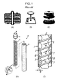
- FIG. 1 shows conventional devices that are mass-produced by applying the clogging-prevention technology utilizing swirl. However, these devices also have various issues which have to be resolved.
- the device shown in FIG. 1(A) is the device developed by the DTRO Company in Germany. The device prevents membrane contamination by promoting turbulence using a protruded internal structure. It is high pressure structure and mainly used in sea water desalination. However, the device in FIG. 1(A) has incomplete turbulence forming capability and it is not proper to be used in high-concentration environment.
- a device shown in FIG. 1(B) is developed by the VSEP Company in United States.
- the device prevents membrane contamination by shear wave directly created by mechanical vibration.
- the device in FIG. 1(B) has excellent contamination prevention capability but has an issue of frequent mechanical troubles since durability is decreased by the fatigue impact on the structure due to vibration. Substantial energy is wasted due to use of separate driving power.
- a device in FIG. 1(C) is developed in Korea. It generates rotating swirl by a rotor that does not have contact with the membrane. The device creates powerful kinetic energy effect on the membrane surface using smaller energy.
- the device in FIG. 1(C) has an advantage that it has excellent membrane contamination-prevention capability through powerful swirl.
- the manufacturing cost is high because of its complicated structure. Therefore, it is difficult to be extensively used in actual fields unless the manufacturing cost decreases.
- FIG. 1(D) and FIG. 1(E) show KR Patent No. 0916940 ("Filtration device equipped with spiral support device", 2009.09.04) and US Patent No. 5628909 ("Membrane filters with corkscrew vortex generating means", 1997.05.13).
- the above-mentioned devices generate swirl by inserting a column with spiral-type groove or structure in which flat irons are twisted in spiral-shape in the circular pipes.
- These devices generates swirl by inserting a fixed-shape structure in the circular pipes. They have advantages of low manufacturing cost in application to the fields but have a limitation that swirl is not sufficiently generated. In addition, there is an operation inconvenience that the devices need to be disassembled for washing and replacement since the fixed-shape structure is adopted.
- An embodiment of the present invention is to provide a filtering apparatus for saving energy as well as sufficiently washing a separation membrane in an environment of high concentration by efficiently generating chaos flow by using a structure of a fixed type.
- a filtering apparatus 100 including: at least one flowing portion 110, which original water is brought into and flows in; a separation membrane 120 provided on wall surface of the flowing portion 110 to be supported and passing and filtering the original water brought in the flowing portion 110; an accommodating portion 130, which accommodates the flowing portion 110 inside and which the filtered water formed filtering the original water by the separation membrane 120 flows in and is discharged from, wherein a chaos flow inducing portion 140 for generating chaos flow is arrayed to be fixed inside the flowing portion 110, and a plurality of separable chaos flow induction unit bodies 145 are arrayed in serial in a main flow direction to form at least one line in the chaos flow inducing portion 140.
- array angles of the chaos flow induction unit bodies 145 in the extended direction have at least one value.
- array angles of the chaos flow induction unit bodies 145 adjacent to the predetermined chaos flow induction unit body 145 are vertical to the array angle of the predetermined chaos flow induction unit body 145.
- the chaos flow induction unit bodies 145 are separately arrayed at more than one predetermined interval(s).
- chaos flow inducing portion 140 more than two chaos flow induction unit bodies 145 are densely arrayed to make a set and each set of the chaos flow induction unit bodies 145 are separately arrayed at more than one predetermined interval(s).
- the chaos flow inducing portion 140 further comprises a separation supporter 144 for separately fixing and supporting the chaos flow induction unit bodies 145.
- the serial array direction of the chaos flow induction unit bodies 145 is an extended direction
- the chaos flow induction unit bodies 145 includes a plane portion 141 formed in a direction, which is parallel to the extended direction, and at least one protruded portion 142 formed to be protruded from each of an upper surface and a lower surface of the plane portion 141.
- the protruded portions 142 are arrayed to form inclination angles of 0° to 90° to the extended direction. In the chaos flow induction unit bodies 145, the protruded portions 142 are arrayed to form inclination angles of 30° to 60° to the extended direction.
- the protruded portion 142 formed on the upper surface of the plane portion 141 has an inclination angle, which is different from that of the protruded portion 142 formed on the lower surface of the plane portion 141.
- the plane portion 141 and the protruded portion 142 are formed to be disassembled and assembled.
- the number of the protruded portions 142 formed on the plane portion 141 varies.
- a filtering apparatus with a separation membrane used in a field of water treatment has an effect of sufficiently washing a separation membrane in an environment of high concentration by removing contaminant accumulated in the separation membrane by generation of swirl, thereby maximizing efficiency in filtering.
- the filtering apparatus of the present invention has an effect of efficiently generating chaos flow by designing and applying an optimal chaos flow inducing shape through flow analysis. Accordingly, there is an advantage that the filtering apparatus is flexibly used in an environment of high concentration.
- the filtering apparatus has an advantage that a desired chaos flow inducing portion may be installed without limitation by shapes or sizes of the filtering apparatus by forming arrangement of a plurality of chaos flow induction unit bodies where chaos flow inducing portions are formed to be detachable. Also, there is an advantage that an operation condition desired by a designer is easily realized by controlling occurrence of chaos flow through arrangement interval of the chaos flow induction unit bodies.
- the filtering apparatus generates swirl through a fixed-type structure, which does not require external power differently from prior arts that require additional power for a driving device for rotation or generation of vibration. Accordingly, the filtering apparatus minimizes cost for operation since there is no energy consumption for driving. Also, the filtering apparatus has superior durability to the prior arts by solving problems such as damages or abrasion due to vibration occurring at the time of driving. Therefore, management of the driving portion such as replace of consumable supplies due to abrasion is not required and replacement life of the device due to deterioration extends, thereby minimizing resources such as manpower, time and cost for operation and making the filtering apparatus economical.
- filtering apparatus 110 flowing portion 120: separation membrane 130: accommodating portion 140: chaos-flow inducer 141: plane portion 142: protruded portion 143: groove 144: separation supporter 145: chaos flow induction unit body
- the present invention suggests the filtering apparatus that performance in removing particles is remarkably improved by generating stronger chaos flow than the prior part when swirl is generated in original water with a fixed structure.
- a mixing effect is rapidly increased by introducing chaotic advection.
- the present invention intents to design an optimal shape of a chaos-flow inducer by applying a numerical analysis technique to flow analysis of a chaotic mixer (Reference: Kang, T. G. and Kwon, T. H., 2004, "Colored particle tracking method for mixing analysis of chaotic micromixers," J. Micromech. Microeng. Vol. 14, pp.891-899 ).
- the present invention assumes that any unit shape is formed to be periodically repeated in a shape of an inducer generating such a chaos flow.
- a unit shape is formed to be periodically repeated in a shape of a conventional swirl generator shown in FIG. 1(D), (E) .
- a velocity field may be efficiently computed by reducing a size of a flow device based on periodicity of the shape itself in the flow device with the above-mentioned form.
- a boundary condition and an incompressible normal state Navier-Stokes equation for obtaining a velocity field are represented by Equation 1 below.
- Equation 2 A condition such as following Equation 2 as a boundary condition for satisfying periodicity of the velocity field is introduced.
- Line 3 of Equation 1 shows a condition that a velocity becomes 0 in a wall surface.
- Lines 4 and 5 of Equation 1 show a condition such as a pressure difference between the inlet and the outlet. Equation 2 shows the same velocity condition in the inlet and the outlet.
- the Navier-Stokes equation is one of representative non-linear equations, a linearized solution is not obtained through the Navier-Stokes equation.
- Flow is generally analyzed based on a numeral analysis technique.
- a velocity field is obtained by using an analysis code based on a finite element method.
- a mixing phenomenon is examined in a kinematical viewpoint of fluid particles without respect to spread of the fluid particles.
- particles having different colors according to the type of fluids are tracked based on the velocity field, which is computed from the inlet to the outlet of the micro-mixer.
- a color given to each particle as information showing the type of fluid plays a key role in visualizing a mixing phenomenon together with position information of the particle. Equation 3 needs to be solved to track the position of the particle.
- Equation 3 x and u represent a position of particles and a velocity vector.
- Information on a velocity at a position of a particle is required for integral calculus of Equation 4. To achieve this, it is required to find an element included in the position of a particle and compute a velocity of a particle through an interpolation process based on a velocity at a node of the element.
- a particle is moved to a new position based on a quaternary Runge-Kutta method (RK4) in integral calculus of Equation 4. This process is repeated until all particles arrive at the outlet of the mixer.
- RK4 quaternary Runge-Kutta method
- Equation 5 is a mixing entropy, which is newly defined based on the information entropy.
- Equation 6 S, S max and S 0 respectively represent a mixing entropy in a predetermined cross section, a maximum entropy at an ideal mixing state, and entropy computed from initial particle distribution of the inlet.
- a value of k is 1. Otherwise, the value of k is 0.
- the present invention intents to suggest an optimal shape of a 3-dimensional structure that efficiently generates powerful chaos flow based on theoretical background as described above. Also, an actual trace of the particles is visualized while tracking particles based on the flow analysis result. The degree of chaos of flow generated by the shape of the chaos-flow inducer is evaluated by the mixing entropy (Equation 6) computed based on the particle tracking result.
- Reynolds number (Re) of flow inside the separation membrane device ranges from 10 to 10,000 at a real driving condition.
- a volumetric ratio of particles increases and viscosity of working fluids rapidly increases, to cause rapid decrease of the Reynolds number at the rear portion of the separation membrane device.
- the laminar flow region changes and the above-mentioned range of the Reynolds number (Re) is derived from the expectation.
- selected design of the chaos-flow inducer needs to be designed to secure the motion of the chaotic particles in diverse Reynolds number regions.
- Structures used in the analysis include (i) LPD shape, (ii) impeller shape, and (iii) flat panel shape with an inclined groove. Characteristics of flows generated in each structure will be introduced.
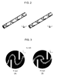
- FIG. 2 shows a design shape of a chaos-flow inducer utilizing a structure of a low pressure drop (LPD) shape, i.e., a LPD mixer.
- LPD low pressure drop
- the LPD shape indicate a shape that two structures of a semielliptic shape are inserted to be orthogonally overlapped inside the round pipe.
- the LPD mixer is widely used in diverse fields nowadays. When a 3-dimensional helical velocity field is induced in each cross section, the LPD mixer is classified into an RL shape that a rotation direction of flow periodically changes according to the shape of the swirl inducer and an RR shape having a regular rotation direction.
- FIG. 3 shows cross-sectional views of a velocity field in flow by the LPD shape. That is, FIG. 3 shows how a velocity component rotating in a cross section of a pipe by two pairs of 3-dimensional structures of a semielliptic shape, which are installed on a round pipe is generated. As confirmed in FIG. 3 , it is known through flow analysis that the fluid rotates in both of two cases and two intersecting semielliptic plates makes a fluid rotate vertically to an axial direction of a pipe.
- FIG. 4 shows a particle tracking analysis result according to Reynolds number's change in an LPD-RL type.
- FIG. 5 shows a particle tracking analysis result according to Reynolds number's change in an LPD-RR type. That is, FIGS. 4 and 5 show a particle trace in each cross section when fluid particles are introduced to an inlet of a separation membrane device by using a velocity field, which is obtained by numeral analysis. It is known with reference to FIG. 4 and FIG. 5 that as the Reynolds number increases, a chaotic flow tendency grows stronger and a complicated motion trace of particles is generated by chaotic advection. Also, mixing enhancing performance of the RL-type is excellent in a region that the Reynolds number is small.
- a separation membrane device adopting both the RL-type and the RR-type may be used in case of the above-mentioned shape. It is expected that contamination of the separation membrane is minimized and performance is maximized through uniform mixing in diverse Reynolds number regions.
- a low pressure region is created locally around the semielliptic structure.
- the pressure is lower than saturate vapor pressure, cavitation may be generated.
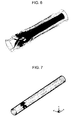
- FIG. 7 shows an impeller shape.
- swirl is generated in a process that a rotation motion is generated while injected fluid goes through a fixed impeller, and the generated swirl is transferred to the lower portion of the pipe due to inertia.
- FIG. 8 shows the computed particle traces in a flow of a swirl inducer in a fixed impeller shape.
- the fluid particle rotates with a complicated aspect after going through the impeller.
- FIGS. 8(A) to 8(C) it is confirmed in FIGS. 8(A) to 8(C) that as the Reynolds number increases, the number of fluid rotations per unit length increases in an axial direction of the pipe.
- FIG. 9 shows a flat panel shape with an inclined groove.
- the flat panel shape with the inclined groove is inserted into a round pipe and a pair of flat panels forming an angle of 90° to each other make one cycle.
- the inclined groove generates a double-helical flow.
- One cycle is formed of helical flows.
- Two helical flows show a characteristic that flow lines cross to each other when the two helical flows are projected on the same plane.
- the fluid particle shows a chaotic mixing characteristic.
- FIG. 10 shows a shape of two counter-rotating flows that rotation is generated in two opposite directions by the inclined groove carved on the surface of the flat panel.
- a velocity component exists in a horizontal direction due to the inclined groove carved on the surface of the flat panel and a helical flow rotating in different directions of left/right or up/down in the flat panel is induced (see references: A.D. Stroock et al., Science, 2002, 295:647-51 , T.G. Kang and T.H. Kwon, J Micromech Microeng, 2004, 14:891-99 , T.G. Kang et al., Microfluid Nanofluid, 2008, 4:589-99 )
- FIG. 11 shows a cross section velocity field shape in a flow by the flat panel shape with the inclined groove.
- FIGS. 11 (A) and (B) respectively show results of the cases that the Reynolds number is 10 and 1000.
- FIG. 11 (A) when the Reynolds number is 10, a flow rotating in a cross section exists but there is a tendency that the flow is narrowly generated in a region near the groove.
- FIG. 11 (B) it is confirmed in FIG. 11 (B) that when the Reynolds number is increased by 1000, a larger swirl is generated.
- a position of fluid particles is tracked by using a velocity field, which is obtained as shown in FIG. 11 , in order to check which motion trace the fluid particle arrayed in a vertical direction in the inlet shows while going through the swirl inducer.
- FIG. 11 shows a cross section velocity field shape in a flow by the flat panel shape with the inclined groove.
- (iii) shape shown in FIG. 10 to FIG. 12 i.e., a separation membrane filtering apparatus, in which the chaotic advection is realized in the wide Reynolds number region when the flat panel shape with the inclined groove is optimized, may be manufactured.
- a factor affecting the degree of chaos of the flow system is as follows:
- the present invention intends to suggest an optimal shape by systematically analyzing the effect that the design factors affect the flow generated by the flat panel shape with the inclined groove.
- the design factor is set as a length(L) of the inducer, a gap(d) between the inducers, and a thickness(t) of the groove.
- FIG. 13 shows that the design factor of the flat panel shape with the inclined groove is more specifically defined.
- D represents a diameter of a round pipe receiving the inducer.
- analysis is executed based on a commercial program COMSOL to grasp the flow tendency according to change of the design factor.
- a model for analysis has a pipe diameter(D) of 20mm, and a width of the inducer is fixed to be the same as the diameter of the pipe.
- the depth of the groove is 2.5mm and a height of the inducer including the groove is 6mm.
- the groove forms 45° with a z-axis and a gap between the grooves is fixed to be 2.5mm.
- analysis is executed by changing the design factor and the Reynolds number. Since the flow pattern shows periodicity, only two-cycles are analyzed for the sake of convenience. Length of Inducer, L Gap of Inducer, d Thickness of Groove, t Reynolds number, Re 1.5D 0.5D 1mm 100 3D D 2.5mm 500 4.5D 1,000 5,000
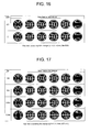
- FIG. 14 to FIG. 17 show flow field cross section analysis results according to change of each design factor.
- FIG. 14 shows a flow field according to UD change
- FIG. 15 shows a flow field according to t change
- FIG. 16 shows a flow field according to d/D change
- FIG. 17 shows a flow field according to Re change.
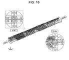
- FIG. 18 shows a particle trace is examined in an outlet by setting up the position of the particle in an inlet.
- the particle position in the outlet is marked by a dot and a route of particles is marked by a line.
- FIG. 19 shows a result according to parameter change of each shape when the Reynolds number is 500.
- FIG. 21 shows a pressure difference in the inlet and the outlet in an analysis region.
- UD is marked on an x-axis. The larger the UD is, the more the pressure loss increases.
- the UD is a ratio of a pipe diameter to an inducer length. As the value increase, the length of the inducer becomes longer. As the length of the inducer becomes longer, the pressure loss increase.
- d/D is a ratio of a pipe diameter to a gap between inducers. As the value increase, the gap of the inducer becomes larger. As the gap of the inducer becomes larger, the length of the pipe becomes larger to cause increase of the pressure loss.
- FIG. 22 shows a pressure change in a z-axis according to Reynolds number and t in a flat panel shape with an inclined groove.
- the pressure loss as well as the velocity loss shows a small value.
- the velocity loss of a z-axis component as a flowing direction affects the pressure loss.
- the pressure loss according to the Reynolds number in the same t as the Reynolds number increases, the higher velocity is required to cause increase of the pressure loss since the Reynolds number is a function based on the velocity in case that the same fluid is used.
- FIG. 23 is a conceptual view showing a basic configuration of the filtering apparatus.
- the filtering apparatus 100 includes a flowing portion 110, a separation membrane 120, and a accommodating portion 130 as a configuration for bringing original water in, filtering the original water using the separation membrane, and discharging the filtered water.
- the present invention also includes a chaos flow inducing portion 140, which is optimally designed based on the analysis described above. Each portion of the present invention will be described in detail hereinafter.
- the filtering apparatus 100 includes the flowing portion 110, the separation membrane 120 and the accommodating portion 130.
- Original water is brought into and flows in the flowing portion 110.
- the flowing portion 110 is accommodated inside the accommodating portion 130.
- the separation membrane 120 is included to be supported on a wall surface of the flowing portion 110, and filters the original water brought in the flowing portion 110. That is, the original water passes the separation membrane 120 included on the wall surface of the flowing portion 110 and moves to a space between the flowing portion 110 and the accommodating portion 130.
- the original water is changed into filtered water by being filtered in the separation membrane 120. Accordingly, the filtered water flows inside the accommodating portion 130 and is discharged by an individual discharging port included in the accommodating portion 130 to obtain finally filtered water.
- the chaos flow inducing portion 140 is fixed inside the flowing portion 110 and removes contaminant accumulated in the separation membrane 120 by generating chaos flow.
- the optimum design of the chaos flow inducing portion 140 will be described in detail hereinafter.
- the filtering apparatus 100 may be configured without limitation.
- FIG. 23A and FIG. 23B show exemplary embodiments that the filtering apparatus 100 is realized in the simplest format. Since each of the flowing portion 110 and the accommodating portion 130 has a pipe shape, the filtering apparatus 100 has a double-pipe shape.
- FIG. 23C shows diverse exemplary embodiments that one or more flowing portion(s) 110 are included in the accommodating portion 130. As shown in FIG. 23C , a plurality of flowing portions 110 may be included inside the accommodating portion 130. When a plurality of flowing portions 110 are included inside the accommodating portion 130, the flowing portions 110 may be radially arrayed.
- the filtering apparatus 100 may be realized in the very simple form as shown in FIG. 23 and it will be more specifically described hereinafter. When the filtering apparatus 100 is realized as shown in FIG. 23 , the filtering apparatus 100 may be simply installed on a fluid channel of a water treatment device, thereby minimizing expenses for facilities and obtaining an economical effect.
- the filtering apparatus 100 may secure diverse advantages that it is eco-friendly, that water purity is stably controlled with no regard to the type of contaminants, and that it is easily managed according to the realization of automated processes by obtaining filtered water by filtering original water through the separation membrane 120.
- the separation membrane is washed by applying a 3G swirl generating technology to prevent accumulation of the contaminant filtered by the separation membrane, unnecessary motions or external power is not required differently from the conventional swirl generating devices.
- the chaos flow inducing portion 140 for more effectively generating chaos flow in comparison with the conventional swirl generating device is provided.
- the filtering apparatus 100 Since the chaos flow inducing portion 140 generates swirl by its shape, external power is not required and there is no motion according to the generation of swirl due to the structure of the chaos flow inducing portion 140. Since the problems including external power and generation of motions are excluded in the chaos flow inducing portion 140, the filtering apparatus 100 is very efficient in view of saving of cost and energy for operation in comparison with the conventional devices. In addition, since the filtering apparatus 100 does not require diverse structures for operation using external power, the filtering apparatus 100 may be easily designed and manufactured. There is also an advantage that since there is little limitation on the configuration and the installation position according to the simplified structure, a range of application is rapidly expanded. In addition, since no motion is generated in the structure for generating swirl in the filtering apparatus 100, the problems including vibration generated by the motion of the components and deterioration of durability according to fatigue shock, which is generally generated by vibration, are excluded.
- a shape of the chaos flow inducing portion 140 will be specifically described with reference to the above description as follows.
- a plurality of separable chaos flow induction unit bodies 145 are arrayed in series in a main flow direction to be formed in at least one line. It is well known that when unit bodies with the same shape inside the round pipe are cyclically arrayed in series, swirl is efficiently generated. Accordingly, the chaos flow induction unit bodies 145 may be formed to have the same shape. However, the chaos flow induction unit bodies 145 may have more than two different shape that are similar and symmetrical to each other, or have one shape in a section that high concentration of original water is contained and the other shape in a section that low concentration of original water is contained. That is, the chaos flow induction unit bodies 145 may have different shapes.
- the chaos flow induction unit bodies 145 are formed to be separable and are arrayed in series is differentiated from that of the conventional swirl generating devices.
- the conventional swirl generating device is formed such that an integrally formed structure is inserted into a pipe but the present invention is formed such that they are separable. Accordingly, the present invention has many advantages in installation or operation.
- the filtering apparatus 100 has a round pipe shape as shown in the drawing, it is apparent that the length of the pipe may be changed.
- the conventional swirl generating device has the integrally formed swirl generating device, there is a disadvantage that the length of the swirl generating device needs to be manufactured according to the length of the pipe.
- the chaos flow inducing portion 140 of the present invention is very conveniently installed and manufactured since the length is fitted by assembling the required number of separable chaos flow induction unit bodies 145 according to the length of the pipe.
- the chaos flow inducing portion 140 has a structure that the separable unit bodies are assembled, the chaos flow inducing portion 140 may be more easily replaced and washed and costs less than the integrally formed conventional swirl generating device.
- the integrally formed device needs to be entirely replaced.
- the present invention is partially damaged, only the damaged unit body needs to be replaced. That is, the present invention is much superior to the conventional swirl generating device in consideration of convenience for user and cost.
- the filtering apparatus 100 When the filtering apparatus 100 has a shape of a linear pipe, there is no problem in applying the conventional swirl generating device. However, in particular cases such that the filtering apparatus 100 has a curved pipe shape, the conventional swirl generating device may have a problem in installation itself. As described above, since the chaos flow inducing portion 140 has the structure that the separable unit bodies are assembled, the chaos flow inducing portion 140 is less limited by the shape of the filtering apparatus 100 to be widely applied in the actual fields.
- FIG. 23 does not show specific shapes of the chaos flow induction unit bodies 145. It means that the present invention is not limited by the optimized shape in the description hereinafter. That is, the chaos flow induction unit bodies 145 may be designed through an optimization process, which will be described hereafter based on the studies as described above. However, the present invention is not limited thereto and may be formed of any other shapes under the condition that chaos flow is efficiently generated.
- the chaos flow inducing portion 140 is configured as shown in FIG. 24 such that the array angle of the chaos flow induction unit bodies 145 has at least one value in the extended direction. The array angle is marked in "8" in FIG. 24 .
- the array angle of the chaos flow induction unit bodies 145 has one value, it means that all chaos flow induction unit bodies 145 are arrayed side by side in the extended direction. That is, the array angle of the chaos flow induction unit bodies 145 shows a shape of FIG. 24B.
- FIG. 24(C) shows a case that the array angle of the chaos flow induction unit bodies 145 has two values. One value forms 0 ° and the other has 90° based on a reference line.
- FIG. 24(A) shows a 3-dimensional shape of FIG. 24(C).
- FIG. 24(D) shows a case that the array angle of the chaos flow induction unit bodies 145 has three values. Each of the array angles is 0°, 60° and 120°.
- the inclined groove when the flat panel shape with the inclined groove is adopted as a basic shape, and a pair of flat panels forming an angle of 90° form one cycle, the inclined groove generates intercrossing double-helical flow.
- the intercrossing two flow shapes are cyclically repeated, it is known that the fluid particles show a chaotic mixing characteristic.
- the array angle of the chaos flow induction unit body 145 adjacent to a predetermined chaos flow induction unit body 145 may be vertical to the array angle of the predetermined chaos flow induction unit bodies 145 in the chaos flow inducing portion 140 on the basis of the array angle of the predetermined chaos flow induction unit bodies 145.
- This array shape is shown in FIG. 24(A) and FIG. 24(C) .
- the array shape is the most preferable embodiment with the premises that the chaos flow induction unit bodies 145 has the flat panel shape with the inclined groove as a basic shape.
- the chaos flow induction unit bodies 145 are formed of other shapes, values of theoretically or experimentally better array angles may be chosen.
- the chaos flow induction unit bodies 145 are more concentrated, the chaos flow is well generated.
- the chaos flow induction unit bodies 145 may be properly arrayed in diverse separation gaps. For example, if concentration of the original water to be filtered by the filtering apparatus is high, the separation gap is designed to be narrow. If the original water has high concentration in one section and low concentration in the other section, it is designed to have a narrow separation gap in the section of high concentration and a wide separation gap in the section of low concentration. That is, it is designed to have diverse widths of the separation gaps.
- the chaos flow induction unit bodies 145 are arrayed at one or more predetermined interval. It will be more specifically described as follows.
- the chaos flow induction unit bodies 145 may have a shape that they are arrayed closely to each other as shown in FIG. 25(A) . This case means that the chaos flow induction unit bodies 145 are separately arrayed at intervals with a single value 0.
- the chaos flow induction unit bodies 145 may be separately arrayed at the same intervals with any single value.
- two chaos flow induction unit bodies 145 may make a pair. In each pair of chaos flow induction unit bodies 145, one pair of chaos flow induction unit bodies 145 have a gap of a and the other pair of chaos flow induction unit bodies 145 have a gap of b.
- FIG. 25(D) shows a shape that each set is arrayed at the same intervals such that two chaos flow induction unit bodies 145 are densely arrayed to form a set and the chaos flow induction unit bodies 145 of one set are formed to be vertical to each other.
- a has a value 0 in the exemplary embodiment of FIG. 25(C) .
- the shape may be the most preferable exemplary embodiment.
- the shape may be the most preferable exemplary embodiment under the condition that the basic shape of the chaos flow induction unit bodies 145 is the flat panel shape with the inclined groove.
- the chaos flow induction unit bodies 145 have other shapes, it is apparent that values of theoretically or experimentally better separation gap may be chosen.
- the chaos flow inducing portion 140 may further include a separation supporter 144 for separately fixing and supporting the chaos flow induction unit bodies 145. Since the separation supporter 144 only needs to fix and support the array by properly controlling the gap of the chaos flow induction unit bodies 145, the shape of the separation supporter 144 is not limited under the condition that the separation supporter 144 is disassembled from and assembled with the chaos flow induction unit bodies 145. Also, since the chaos flow induction unit bodies 145 are the structures affecting the fluid flow such as generating of a chaos flow, the separation supporter 144 may be formed not to affect the fluid flow.
- the present invention suggests the flat panel shape with the inclined groove as the basic shape of the chaos flow induction unit bodies 145 as shown in FIG. 13 .
- the chaos flow induction unit bodies 145 includes a plane portion 141 and at least one protruded portion 142.
- the plane portion 141 is formed in parallel to the extended direction.
- At least one protruded portion 142 is formed to be protruded in a vertical direction to each of the upper surface and lower surface of the plane portion 141. It is apparent that a groove 143, i.e., a fluid channel width g (see FIG. 13 ), between the protruded portions 142, is formed.
- the protruded portions 142 arrayed to form an inclination angle of 0° to 90° in the extended direction may be formed to be inclined. Diverse inclination angles may be adopted in designing. More preferably, in the chaos flow induction unit bodies 145, the protruded portions 142 arrayed to form an inclination angle of 30° to 60° in the extended direction.
- FIG. 26 shows the case that an inclination angle of the protruded portion 142 formed on an upper surface of the plane portion 141 is the same as that of the protruded portion 142 formed on a lower surface of the plane portion 141. More preferably, in order to activate the induce of the chaos flow in the chaos flow induction unit bodies 145, the protruded portion 142 formed on the upper surface of the plane portion 141 may be arrayed to have an inclination angle, which is different from that of the protruded portion 142 formed on the lower surface of the plane portion 141.
- the shape of the chaos flow inducing portion 140 may be easily changed according to diverse characteristics such as flow or concentration of the introduced original water. For example, the separation gap between each unit body may be controlled properly as needed and each unit body has different shapes.
- the plane portion 141 and the protruded portion 142 may be formed to be disassembled or assembled and be easily changed by simplifying of the shape in the chaos flow induction unit bodies 145.
- the disassembling and assembling structure may be simply realized.
- a groove is formed on the plane portion 141 and an inserting portion is on one side of the protruded portion 142.
- the plane portion 141 and the protruded portion 142 may be disassembled or assembled by inserting the inserting portion of the protruded portion 142 into the groove of the plane portion 141. That is, diverse structures may be realized as a matter of convenience of a designer.
- the number of the protruded portions 142 provided on the plane portion 141 may vary.
- the structure may be very simply realized.
- the structure that the number of the protruded portions 142 varies may be realized by forming a plurality of grooves in the plane portion 141 and putting the protruded portions 142 in all or parts of the grooves.
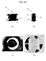
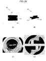
- FIG. 27 to FIG. 29 show the flat panel shapes with the inclined groove as the basic shape described above according to first to third exemplary embodiments.
- the groove i.e., the fluid channel width g
- the third exemplary embodiment of FIG. 29 shows the case that only one protruded portion 142 is formed on the plane portion 141, i.e., the shape that the fluid channel width g is maximized.
- the inclination angle of the protruded portion 142 formed on the upper surface of the plane portion 141 is opposite to that of the protruded portion 142 formed on the lower surface of the plane portion 141.
- FIG. 29(A), FIG. 29(B), FIG. 29(C), and FIG. 29(D) respectively show a shape shown from the upper surface, a shape shown from a side, an example of insertion into the filtering apparatus, and a fluidized bed.
- FIG. 27(D) , FIG. 28(D) , and FIG. 29(D) it is known that the chaos flow is most actively induced in the fluidized bed of FIG. 29(D) .
- the present invention suggests the optimal exemplary embodiment of FIG. 33 in consideration that as the fluid channel width g, i.e., the groove 143, gets wider, the chaos flow generating effect increases.
- the optimal exemplary embodiment of FIG. 33 as shown in FIGS. 33(A), and 33(B) , only one protruded portion 142 is formed on each of the upper surface and the lower surface of the plane portion 141 and an inclination angle becomes 45°.
- the angle of the upper surface of the protruded portion 142 is formed in an opposite direction to the angle of the lower surface of the protruded portion 142.
- FIG. 30 to FIG. 32 show test results of flux, consumption power, and loss of head according to the number of the chaos flow induction unit bodies 145. It was determined based on the test results that the effective chaos flow induction unit bodies 145 of about 33% per one module are the most preferable in consideration of decrease of flux, consumption power and loss of head. In consideration of the test result, as shown in FIG. 339C), a separation gap is set up such that the ratio of the chaos flow induction unit bodies 145 becomes 33% inside the filtering apparatus 100 in the optimal exemplary embodiment of FIG. 33 . The real insertion form is shown in FIG. 33(D) .
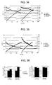
- FIG. 34 shows a test result on the performance evaluation of the chaos flow induction unit bodies 145 according to the optimal exemplary embodiment using the BCS inflow water (TS 1 %) as a subject.
- the test result shows the comparison result under the condition of low concentration.
- FIG. 34 according to the operation result that the BCS inflow water was used to the maximum concentration of 75%, when the chaos flow induction unit bodies 145 according to the optimal exemplary embodiment were adopted, flux increased to 17% on average and operation power of about 10% was reduced in comparison with the case that the chaos flow induction unit bodies 145 were not inserted.
- FIG. 34 shows a test result on the performance evaluation of the chaos flow induction unit bodies 145 according to the optimal exemplary embodiment using the BCS inflow water (TS 1 %) as a subject.
- the test result shows the comparison result under the condition of low concentration.
- FIG. 34 according to the operation result that the BCS inflow water was used to the maximum concentration of 75%, when the chaos flow induction unit bodies 145 according to the optimal exemplary embodiment were adopted
- FIG. 35 shows a test result on performance evaluation of the chaos flow induction unit bodies 145 according to the optimal exemplary embodiment using undiluted solution of livestock waste water (TS 4.7%) as a subject. That is, FIG. 35 shows the test result under the condition of high concentration. As shown in FIG. 35 , according to the operation result that high concentration undiluted solution of livestock waste water (TS 4.7%) was used to the maximum concentration of 56%, when the chaos flow induction unit bodies 145 according to the optimal exemplary embodiment were adopted, flux increased to 50% on average and operation power of about 5% was reduced in comparison with the case that the chaos flow induction unit bodies 145 were not inserted.
- FIG. 36 is a graph showing the concise comparison result that the above test results are rearranged.
- the chaos flow induction unit bodies 145 according to optimal exemplary embodiment were used, flux increased to 17% on average and operation power of about 10% was reduced in the low concentration of the BCS inflow water (TS 1 %) in comparison with the case that the chaos flow induction unit bodies 145 were not inserted. Also, flux increased to 50% on average and operation power of about 5 was reduced in the high concentration undiluted solution of livestock waste water (TS 4.7%). That is, the performance evaluation result of the chaos flow induction unit bodies 145 according to the optimal exemplary embodiment confirmed that the higher the concentration of the introduced sample becomes by the power of swirl generated by chaos flow induction unit bodies 145, the more the flux of the treated water increases.
- a filtering apparatus for saving energy as well as sufficiently washing a separation membrane in an environment of high concentration by efficiently generating chaos flow by using a structure of a fixed type.
Landscapes
- Chemical & Material Sciences (AREA)
- Chemical Kinetics & Catalysis (AREA)
- Life Sciences & Earth Sciences (AREA)
- Hydrology & Water Resources (AREA)
- Engineering & Computer Science (AREA)
- Environmental & Geological Engineering (AREA)
- Water Supply & Treatment (AREA)
- Organic Chemistry (AREA)
- Separation Using Semi-Permeable Membranes (AREA)
- Physical Or Chemical Processes And Apparatus (AREA)
Applications Claiming Priority (1)
| Application Number | Priority Date | Filing Date | Title |
|---|---|---|---|
| KR1020110109868A KR101320467B1 (ko) | 2011-10-26 | 2011-10-26 | 고정형 카오스 유동 유도체를 구비하는 여과장치 |
Publications (1)
| Publication Number | Publication Date |
|---|---|
| EP2586520A1 true EP2586520A1 (de) | 2013-05-01 |
Family
ID=46045707
Family Applications (1)
| Application Number | Title | Priority Date | Filing Date |
|---|---|---|---|
| EP12002934.3A Withdrawn EP2586520A1 (de) | 2011-10-26 | 2012-04-26 | Filtervorrichtung mit festem Chaosdurchflussinduzierer |
Country Status (5)
| Country | Link |
|---|---|
| US (1) | US20130105381A1 (de) |
| EP (1) | EP2586520A1 (de) |
| KR (1) | KR101320467B1 (de) |
| CN (1) | CN103889541A (de) |
| WO (1) | WO2013062199A1 (de) |
Cited By (2)
| Publication number | Priority date | Publication date | Assignee | Title |
|---|---|---|---|---|
| US20160220960A1 (en) * | 2013-09-18 | 2016-08-04 | Chemetics, Inc. | Hollow fibre membrane module with improved fluid flow distribution |
| EP3643385A4 (de) * | 2017-06-21 | 2021-04-28 | M. Technique Co., Ltd. | Filtrationsmembranmodul und filtrationsverfahren |
Families Citing this family (4)
| Publication number | Priority date | Publication date | Assignee | Title |
|---|---|---|---|---|
| JP2014198324A (ja) * | 2013-03-29 | 2014-10-23 | ソニー株式会社 | マイクロ流路及びマイクロ流体デバイス |
| FR3024664B1 (fr) * | 2014-08-11 | 2020-05-08 | Technologies Avancees Et Membranes Industrielles | Nouvelles geometries d'elements tubulaires multicanaux de separation par flux tangentiel integrant des promoteurs de turbulences et procede de fabrication |
| CN108543422A (zh) * | 2017-12-21 | 2018-09-18 | 刘振民 | 一种分离介质自清洁连续分离方法及装置 |
| CN111484151A (zh) * | 2020-04-17 | 2020-08-04 | 莱特莱德(北京)环境技术股份有限公司 | 一种户外利用dtro生产饮用水的系统及方法 |
Citations (7)
| Publication number | Priority date | Publication date | Assignee | Title |
|---|---|---|---|---|
| US3256678A (en) * | 1960-02-15 | 1966-06-21 | Commissariat Energie Atomique | Devices for the separation of fluids by diffusion through a porous wall |
| US3672509A (en) * | 1969-07-08 | 1972-06-27 | Solco Basel Ag | Dialysis apparatus |
| US3922220A (en) * | 1973-11-02 | 1975-11-25 | Kenics Corp | Permeable membrane separation device and method |
| US4123178A (en) * | 1977-03-21 | 1978-10-31 | General Signal Corporation | In-line blender |
| US4902418A (en) * | 1985-11-22 | 1990-02-20 | Sulzer Brothers Limited | Element having a porous wall |
| US5628909A (en) | 1993-03-19 | 1997-05-13 | Isis Innovation Limited | Membrane filters with corkscrew vortex generating means |
| KR100916940B1 (ko) | 2008-10-17 | 2009-09-15 | 김창용 | 나선형 지지구가 구비된 여과장치 |
Family Cites Families (5)
| Publication number | Priority date | Publication date | Assignee | Title |
|---|---|---|---|---|
| US3788471A (en) * | 1969-07-08 | 1974-01-29 | Solco Basel Ag | Dialysis apparatus |
| US7540475B2 (en) * | 2005-09-16 | 2009-06-02 | Battelle Memorial Institute | Mixing in wicking structures and the use of enhanced mixing within wicks in microchannel devices |
| JP2008086980A (ja) * | 2006-10-04 | 2008-04-17 | Nippon Solid Co Ltd | 原水の処理方法 |
| KR100842787B1 (ko) * | 2008-04-14 | 2008-07-01 | 정학서 | 알칼리 이온수 자화필터 및 이를 이용한 알칼리 이온수자화정수장치 |
| US7976789B2 (en) * | 2008-07-22 | 2011-07-12 | The Board Of Trustees Of The University Of Illinois | Microfluidic device for preparing mixtures |
-
2011
- 2011-10-26 KR KR1020110109868A patent/KR101320467B1/ko active Active
-
2012
- 2012-04-26 US US13/457,094 patent/US20130105381A1/en not_active Abandoned
- 2012-04-26 EP EP12002934.3A patent/EP2586520A1/de not_active Withdrawn
- 2012-04-30 CN CN201280052683.4A patent/CN103889541A/zh active Pending
- 2012-04-30 WO PCT/KR2012/003331 patent/WO2013062199A1/en not_active Ceased
Patent Citations (7)
| Publication number | Priority date | Publication date | Assignee | Title |
|---|---|---|---|---|
| US3256678A (en) * | 1960-02-15 | 1966-06-21 | Commissariat Energie Atomique | Devices for the separation of fluids by diffusion through a porous wall |
| US3672509A (en) * | 1969-07-08 | 1972-06-27 | Solco Basel Ag | Dialysis apparatus |
| US3922220A (en) * | 1973-11-02 | 1975-11-25 | Kenics Corp | Permeable membrane separation device and method |
| US4123178A (en) * | 1977-03-21 | 1978-10-31 | General Signal Corporation | In-line blender |
| US4902418A (en) * | 1985-11-22 | 1990-02-20 | Sulzer Brothers Limited | Element having a porous wall |
| US5628909A (en) | 1993-03-19 | 1997-05-13 | Isis Innovation Limited | Membrane filters with corkscrew vortex generating means |
| KR100916940B1 (ko) | 2008-10-17 | 2009-09-15 | 김창용 | 나선형 지지구가 구비된 여과장치 |
Non-Patent Citations (5)
| Title |
|---|
| A.D. STROOCK ET AL., SCIENCE, vol. 295, 2002, pages 647 - 651 |
| KANG, T. G.; KWON, T. H.: "Colored particle tracking method for mixing analysis of chaotic micromixers", J. MICROMECH. MICROENG, vol. 14, 2004, pages 891 - 899 |
| KANG, T. G.; KWON, T. H.: "Colored particle tracking method for mixing analysis of chaotic micromixers", J. MICROMECH. MICROENG., vol. 14, 2004, pages 891 - 899 |
| T.G. KANG ET AL., MICROFLUID NANOFLUID, vol. 4, 2008, pages 589 - 599 |
| T.G. KANG; T.H. KWON, J MICROMECH MICROENG, vol. 14, 2004, pages 891 - 899 |
Cited By (4)
| Publication number | Priority date | Publication date | Assignee | Title |
|---|---|---|---|---|
| US20160220960A1 (en) * | 2013-09-18 | 2016-08-04 | Chemetics, Inc. | Hollow fibre membrane module with improved fluid flow distribution |
| EP3046659B1 (de) * | 2013-09-18 | 2020-05-20 | Chemetics Inc. | Verwendung eines hohlfasermembranmoduls mit verbesserter fluidstromverteilung zur osmotischen membrandestillation |
| EP3643385A4 (de) * | 2017-06-21 | 2021-04-28 | M. Technique Co., Ltd. | Filtrationsmembranmodul und filtrationsverfahren |
| US11161079B2 (en) | 2017-06-21 | 2021-11-02 | M. Technique Co., Ltd. | Filtration membrane module and filtration processing method |
Also Published As
| Publication number | Publication date |
|---|---|
| CN103889541A (zh) | 2014-06-25 |
| KR101320467B1 (ko) | 2013-10-22 |
| WO2013062199A1 (en) | 2013-05-02 |
| US20130105381A1 (en) | 2013-05-02 |
| KR20130045580A (ko) | 2013-05-06 |
Similar Documents
| Publication | Publication Date | Title |
|---|---|---|
| EP2586520A1 (de) | Filtervorrichtung mit festem Chaosdurchflussinduzierer | |
| KR101180746B1 (ko) | 상향류식 여과장치 | |
| JP5594138B2 (ja) | 流体分離素子、流体分離素子用テレスコープ防止板、及び流体分離装置 | |
| CN101500681A (zh) | 高流量盘式过滤器 | |
| EP2752229A1 (de) | Saugvorrichtung für einen gewebefilter und filterungsvorrichtung damit | |
| KR101619181B1 (ko) | 처리효율을 향상시킨 와류형 여과장치 | |
| WO2003008065A1 (en) | Back washing valve and filtering apparatus with the same | |
| Shirzadi et al. | High-resolution numerical simulation of microfiltration of oil-in-water emulsion permeating through a realistic membrane microporous structure generated by focused ion beam scanning electron microscopy images | |
| WO2015187665A2 (en) | Filter arrangement with support core and methods | |
| US20170136393A1 (en) | Support structure for fluid treatment systems having belted filtration systems | |
| EP3097963A1 (de) | Gefalteter filter, abwasseraufbereitungsvorrichtung damit sowie abwasseraufbereitungsverfahren | |
| CA2763022A1 (en) | Uv reactor design having pressure equalizing manifold for increasing uv flux efficiency | |
| US20160114269A1 (en) | Filtering device, ballast water treatment method, and ballast water treatment apparatus using the same | |
| US12263445B2 (en) | Filter membrane with bi-directional flow enhancing features | |
| KR20140054114A (ko) | 액체 특히 폐수를 여과하기 위한 여과장치 및 여과방법 | |
| KR101313631B1 (ko) | 필터관 및 이를 이용한 정수장치 | |
| Chang et al. | Techniques to Enhance Performance of Liquid-Phase Membrane Processes by Improved Control of Concentration Polarization | |
| KR101918934B1 (ko) | 오염수 정화용 스테인리스 필터 모듈 | |
| KR101809816B1 (ko) | 와이어를 이용한 미세버블 생성장치 | |
| KR101361156B1 (ko) | 적층형 디스크 필터 및 이를 이용한 여과기 | |
| KR101162500B1 (ko) | 수처리 장치 | |
| WO2002085493A1 (de) | Filtervorrichtung | |
| Mwanga et al. | Micro and nanobubbles aided membrane processes | |
| US20030029798A1 (en) | Membrane filtration system and method | |
| RU2408409C1 (ru) | Способ очистки фильтроэлементов поверхностного действия с канальной структурой |
Legal Events
| Date | Code | Title | Description |
|---|---|---|---|
| PUAI | Public reference made under article 153(3) epc to a published international application that has entered the european phase |
Free format text: ORIGINAL CODE: 0009012 |
|
| AK | Designated contracting states |
Kind code of ref document: A1 Designated state(s): AL AT BE BG CH CY CZ DE DK EE ES FI FR GB GR HR HU IE IS IT LI LT LU LV MC MK MT NL NO PL PT RO RS SE SI SK SM TR |
|
| AX | Request for extension of the european patent |
Extension state: BA ME |
|
| 17P | Request for examination filed |
Effective date: 20131031 |
|
| RBV | Designated contracting states (corrected) |
Designated state(s): AL AT BE BG CH CY CZ DE DK EE ES FI FR GB GR HR HU IE IS IT LI LT LU LV MC MK MT NL NO PL PT RO RS SE SI SK SM TR |
|
| STAA | Information on the status of an ep patent application or granted ep patent |
Free format text: STATUS: THE APPLICATION IS DEEMED TO BE WITHDRAWN |
|
| 18D | Application deemed to be withdrawn |
Effective date: 20151103 |