EP2586533B1 - Centrifugeuse à vis a bol plein dotée d'une vis sans fin - Google Patents
Centrifugeuse à vis a bol plein dotée d'une vis sans fin Download PDFInfo
- Publication number
- EP2586533B1 EP2586533B1 EP11008664.2A EP11008664A EP2586533B1 EP 2586533 B1 EP2586533 B1 EP 2586533B1 EP 11008664 A EP11008664 A EP 11008664A EP 2586533 B1 EP2586533 B1 EP 2586533B1
- Authority
- EP
- European Patent Office
- Prior art keywords
- screw
- drum
- solid bowl
- edge
- rotation
- Prior art date
- Legal status (The legal status is an assumption and is not a legal conclusion. Google has not performed a legal analysis and makes no representation as to the accuracy of the status listed.)
- Active
Links
Images

Classifications
-
- B—PERFORMING OPERATIONS; TRANSPORTING
- B04—CENTRIFUGAL APPARATUS OR MACHINES FOR CARRYING-OUT PHYSICAL OR CHEMICAL PROCESSES
- B04B—CENTRIFUGES
- B04B1/00—Centrifuges with rotary bowls provided with solid jackets for separating predominantly liquid mixtures with or without solid particles
- B04B1/20—Centrifuges with rotary bowls provided with solid jackets for separating predominantly liquid mixtures with or without solid particles discharging solid particles from the bowl by a conveying screw coaxial with the bowl axis and rotating relatively to the bowl
-
- B—PERFORMING OPERATIONS; TRANSPORTING
- B04—CENTRIFUGAL APPARATUS OR MACHINES FOR CARRYING-OUT PHYSICAL OR CHEMICAL PROCESSES
- B04B—CENTRIFUGES
- B04B1/00—Centrifuges with rotary bowls provided with solid jackets for separating predominantly liquid mixtures with or without solid particles
- B04B1/20—Centrifuges with rotary bowls provided with solid jackets for separating predominantly liquid mixtures with or without solid particles discharging solid particles from the bowl by a conveying screw coaxial with the bowl axis and rotating relatively to the bowl
- B04B2001/2041—Centrifuges with rotary bowls provided with solid jackets for separating predominantly liquid mixtures with or without solid particles discharging solid particles from the bowl by a conveying screw coaxial with the bowl axis and rotating relatively to the bowl with baffles, plates, vanes or discs attached to the conveying screw
Definitions
- the invention relates to a solid bowl screw centrifuge for separating a medium into at least a light and a heavy phase with a rotatable drum and a rotatable therein screw, which has a screw hub with a worm spiral disposed thereon, which forms a heavy-phase conveyor track to this with the Carry out the screw from the drum out of the light phase.
- Solid bowl centrifuges of the above type are used to separate or separate flowable media by means of centrifugal force into at least one light and one heavy phase.
- the heavy phase deposits radially outward in the drum and the light phase floats radially inward thereon.
- the heavy phase is discharged with the rotatable relative to the drum screw from the drum and the light phase discharged by means of about a weir or a paring disc radially inward.
- the invention has for its object to provide a Vollmantelschneckenzentrifuge, by means of which in comparison to known centrifuges in a cost effective manner and in particular with low maintenance costs, a high oil yield can be achieved.
- a solid bowl screw centrifuge for separating a medium into at least one light and one heavy phase with a rotatable drum and a rotatable screw having a screw hub with a spiral screw disposed thereon forming a heavy phase conveyor to take them out of the drum with the screw out of the light phase.
- the conveyor track at least one knife-like element is arranged, which at the Schneckennabe arranged and protrudes from it so far that it dips into the medium to be separated during operation of the solid bowl screw centrifuge.
- a knife-like element which is attached to the screw hub emerges.
- the knife-like element is designed blade-like or plate-shaped, acts like a blade or cutting edge and cuts or cuts through in particular that barrier layer, which would otherwise prevent an increase from light phase to radially inside.
- the blade according to the invention sets the circulating in the drum medium due to its cutting action a relatively low resistance and is therefore subject to only little wear.
- the knife-like element albeit narrow slit cut into the release layer, then float through the then light phase.
- the knife-like element has in particular parallel side surfaces or blade surfaces, on which viewed in the circumferential direction, the medium can slide along resistance largely free.
- the knife surfaces of this type also advantageously extend substantially parallel to the adjacent surfaces of the screw helix.
- the knife-like element according to the invention is therefore preferably attached to the screw hub aligned as well as the adjacent screw helix.
- the element acts as not transverse to the flow like a paddle but extends substantially along the flow through the respective helical turn.
- a continuous spiral screw is used.
- the elements according to the invention have almost no conveying action but merely sever the said barrier layer. Although this also leads to a circulation of the medium itself, this circulation is relatively low due to the cutting action of the elements according to the invention. This is also an advantage of the solution according to the invention, because an excessive circulation in the medium would only worsen the previously achieved separation into light and heavy phase again.
- a plurality of knife-like elements are preferably provided next to one another with surfaces aligned in parallel in a conveying passage or screw flight. Particularly preferably, there are three such elements side by side. It arises with the elements arranged in this way a kind of comb, which introduces cuts into the medium at short intervals. Through these cuts or slots, the light phase can then move radially inward.
- the knife-like elements are mounted according to the invention on a base plate, which is attached to the screw hub exchangeably fixed, in particular screwed there is.
- a base plate which is attached to the screw hub exchangeably fixed, in particular screwed there is.
- Such base plates are also preferably mounted in four successive flights.
- the screw of the solid bowl screw centrifuge according to the invention generally has a cylindrical region and a conical region, wherein the elements according to the invention are preferably arranged in the cylindrical region of the screw. Furthermore, the elements on the screw hub are preferably provided in an area axially outside an inlet area for introducing the medium to be centrifuged.
- the inlet region is designed with openings in the screw hub, through which medium, which was supplied radially inward into the screw hub, can pass radially outward into the separation space between the screw hub and the drum wall.
- the knife-like element is preferably provided with a pointing in the direction of rotation of the screw relative to the drum leading edge, which is designed sharply.
- the front edge of this type forms a cutting edge, which cuts through the medium and the barrier layer located therein in a largely friction-free manner.
- the knife-like element is further preferably provided with a leading edge pointing in the direction of rotation of the screw relative to the drum, which extends obliquely relative to the radial direction of the screw.
- the thus oblique front edge leads to a pulling or pushing cut on the knife-like element according to the invention, whereby its separation behavior is further improved and in particular becomes particularly low in friction.
- a pulling section for which the leading edge is pivoted away from the direction of rotation of the screw relative to the drum from radially inward to radially outward.
- the pointing in the direction of rotation of the screw relative to the drum leading edge is preferably straight.
- the cutting edge of this kind can be produced particularly inexpensively and can also be sharpened cost-effectively.
- the knife-like element is preferably provided with a counter to the direction of rotation of the screw relative to the drum facing back edge, which is designed dull.
- the such back edge thus forms a dull back of the knife.
- a slot is formed through which in particular oil can rise from radially outside to radially inside.
- the knife-like element is further preferably provided with a counter to the direction of rotation of the screw relative to the drum facing the rear edge, which extends substantially parallel to the radial direction and in the direction of rotation of the screw set back.
- Such back edge provided a stable, wide blade for the element according to the invention and supports the preferred pulling cutting action according to the invention.
- the opposite to the direction of rotation of the screw relative to the drum facing back edge is preferably designed straight.
- the back edge of this type can likewise be produced in a particularly cost-effective manner.
- the knife-like element is also advantageously provided with a pointing in the direction of rotation of the screw relative to the drum leading edge and opposite to the direction of rotation of the screw relative to the drum facing back edge, wherein the front edge and the back edge are designed radially inward to radially outwardly facing each other , It is formed in this way a V-shaped in the side view, sheet-like element which is attached to its broad side on the screw hub and thereby has a high rigidity.
- the knife-like element is designed with a radial outer edge relative to the screw hub, which extends substantially tangentially.
- the thus tangentially oriented outer edge is preferably offset radially inwardly, in particular because of the setback in the direction of rotation.
- the outer edge preferably begins behind the radial direction of the screw hub and thus also supports the desired pulling cutting action.
- the outer edge of this type also provides a lifting effect for the medium sliding along it, by means of which medium is conveyed from radially inward to radially outward.
- the outer edge is also preferably less radially than the radially outer edge Helix itself. So it can also dive less far into the medium, as the helix.
- the relative to the screw hub radially outer edge is preferably designed straight.
- the outer edge of this type can also be produced very inexpensively, so that overall the element according to the invention can be manufactured from a sheet metal in a particularly cost-effective and low-grade manner.
- the screw 12 is formed from a tubular or hollow cylindrical screw hub 14, which is surrounded on the outside by a screw helix 16.
- the worm gear 16 extends as a wound sheet of the screw hub 14 radially outward at right angles or with a slightly deviating from the vertical angle so far protruding that it almost touches the associated (not shown) drum of the solid bowl worm centrifuge 10.
- the screw flight 16 dips into a medium located in the associated drum and discharges this a separating heavy phase out of a radially inwardly collecting light phase out.
- inlet openings 18 are formed in the screw hub 14, through which medium can pass radially inwards from the inside of the screw hub 14 in order to be separated there.
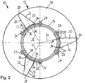
- the single knife-like element 20 is (see Fig. 2 ) is designed as a blade having a straight, sharp leading edge 26, a straight, blunt back edge 28, and a straight radially outer, outer edge 30.
- the front edge 26 is arranged counter to the direction of rotation of the worm 12 relative to the drum from radially inward to radially outward.
- the inclination of the front edge 26 is about 30 ° and is so far that the outer edge 30 begins only behind belonging to this base plate 22 radial direction 32.
- the outer edge 30 then extends tangentially from there over preferably 1/3 of the entire circumferential width of the blade of the knife-like element 20.
- the back edge 28 extends parallel to the radial direction 32 and limits the outer edge 30 radially outwardly just below the radius of the helix 16.
Landscapes
- Centrifugal Separators (AREA)
Claims (10)
- Centrifugeuse à vis sans fin à paroi pleine (10) pour séparer un milieu en au moins une phase légère et une phase lourde, comprenant un tambour rotatif et une vis sans fin (12) pouvant tourner dans celui-ci, la vis sans fin ayant un moyeu de vis (14) avec une hélice de vis (16) disposée sur celui-ci et formant une voie de convoyage pour la phase lourde pour extraire celle-ci hors de la phase légère hors du tambour au moyen de la vis sans fin (12),
au moins un élément en forme de lame (20) étant disposé dans la voie de convoyage, qui est disposé sur le moyeu de vis (14) et qui fait saillie à partir de celui-ci jusqu'à ce qu'il plonge dans le milieu à séparer pendant le fonctionnement de la centrifugeuse à vis à paroi pleine (10),
caractérisée en ce que ledit au moins un élément en forme de lame (20) est monté sur une plaque de base (22) qui est fixée de manière stationnaire et interchangeable au moyeu de vis (14). - Centrifugeuse à vis sans fin à paroi pleine selon la revendication 1,
caractérisée en ce que
la plaque de base (22) est vissée sur le moyeu de vis (14). - Centrifugeuse à vis sans fin à paroi pleine selon la revendication 2,
caractérisée en ce que
l'élément en forme de lame (20) est muni d'un bord avant (26) qui est dirigé dans la direction de rotation de la vis sans fin (12) par rapport au tambour et qui s'étend en oblique par rapport à la direction radiale de la vis sans fin (12). - Centrifugeuse à vis sans fin à paroi pleine selon la revendication 2 ou 3,
caractérisée en ce que
le bord avant (26) dirigé dans la direction de rotation de la vis sans fin (12) par rapport au tambour est conçu rectiligne. - Centrifugeuse à vis sans fin à paroi pleine selon l'une des revendications 1 à 4,
caractérisée en ce que
l'élément en forme de lame (20) est muni d'un bord arrière (28) qui est dirigé en sens opposé à la direction de rotation de la vis sans fin (12) par rapport au tambour et qui est réalisé émoussé. - Centrifugeuse à vis sans fin à paroi pleine selon l'une des revendications 1 à 5,
caractérisée en ce que
l'élément en forme de lame (20) est muni d'un bord arrière (28) qui est dirigé en sens opposé à la direction de rotation de la vis sans fin (12) par rapport au tambour et qui s'étend sensiblement parallèlement à la direction radiale et en retrait dans la direction de rotation de la vis sans fin (12). - Centrifugeuse à vis sans fin à paroi pleine selon la revendication 5 ou 6,
caractérisée en ce que
le bord arrière (28) dirigé en sens opposé à la direction de rotation de la vis sans fin (12) par rapport au tambour est réalisé rectiligne. - Centrifugeuse à vis sans fin à paroi pleine selon l'une des revendications 1 à 7,
caractérisée en ce que
l'élément en forme de lame (20) est muni d'un bord avant (26) dirigé en direction de rotation de la vis sans fin (12) par rapport au tambour et d'un bord arrière (28) dirigé en sens opposé à la direction de rotation de la vis sans fin (12) par rapport au tambour, le bord avant (26) et le bord arrière (28) étant réalisés de manière tournée l'un vers l'autre, vus radialement de l'intérieur vers l'extérieur. - Centrifugeuse à vis sans fin à paroi pleine selon l'une des revendications 1 à 8,
caractérisée en ce que
l'élément en forme de lame (20) est réalisé avec un bord extérieur (30) radialement extérieur par rapport au moyeu de vis (14), qui s'étend sensiblement tangentiellement. - Centrifugeuse à vis sans fin à paroi pleine selon la revendication 9,
caractérisée en ce que
le bord extérieur (30) radialement extérieur par rapport au moyeu de vis (14) est réalisé rectiligne.
Priority Applications (3)
| Application Number | Priority Date | Filing Date | Title |
|---|---|---|---|
| PT110086642T PT2586533T (pt) | 2011-10-28 | 2011-10-28 | Centrífuga de parafuso contínuo de parede sólida com um parafuso contínuo |
| EP11008664.2A EP2586533B1 (fr) | 2011-10-28 | 2011-10-28 | Centrifugeuse à vis a bol plein dotée d'une vis sans fin |
| ES11008664T ES2754754T3 (es) | 2011-10-28 | 2011-10-28 | Centrífuga con tornillo de camisa sólida con un tornillo |
Applications Claiming Priority (1)
| Application Number | Priority Date | Filing Date | Title |
|---|---|---|---|
| EP11008664.2A EP2586533B1 (fr) | 2011-10-28 | 2011-10-28 | Centrifugeuse à vis a bol plein dotée d'une vis sans fin |
Publications (2)
| Publication Number | Publication Date |
|---|---|
| EP2586533A1 EP2586533A1 (fr) | 2013-05-01 |
| EP2586533B1 true EP2586533B1 (fr) | 2019-08-14 |
Family
ID=45065576
Family Applications (1)
| Application Number | Title | Priority Date | Filing Date |
|---|---|---|---|
| EP11008664.2A Active EP2586533B1 (fr) | 2011-10-28 | 2011-10-28 | Centrifugeuse à vis a bol plein dotée d'une vis sans fin |
Country Status (3)
| Country | Link |
|---|---|
| EP (1) | EP2586533B1 (fr) |
| ES (1) | ES2754754T3 (fr) |
| PT (1) | PT2586533T (fr) |
Families Citing this family (2)
| Publication number | Priority date | Publication date | Assignee | Title |
|---|---|---|---|---|
| CN106475234B (zh) * | 2015-08-26 | 2018-10-26 | 苏州瑞威离心分离技术有限公司 | 卧式螺旋卸料沉降离心机 |
| EP4076759A1 (fr) * | 2019-12-19 | 2022-10-26 | Flottweg SE | Moyeu de vis, vis de centrifugeuse et centrifugeuse à vis à bol plein |
Citations (1)
| Publication number | Priority date | Publication date | Assignee | Title |
|---|---|---|---|---|
| US5653673A (en) * | 1994-06-27 | 1997-08-05 | Amoco Corporation | Wash conduit configuration in a centrifuge apparatus and uses thereof |
Family Cites Families (3)
| Publication number | Priority date | Publication date | Assignee | Title |
|---|---|---|---|---|
| DE3301099A1 (de) * | 1983-01-14 | 1984-12-06 | KHD Humboldt Wedag AG, 5000 Köln | Vorrichtung zur entfeuchtung von schlamm im zentrifugalfeld einer vollmantel-zentrifuge |
| DE10055798A1 (de) * | 2000-11-10 | 2002-05-23 | Westfalia Separator Ind Gmbh | Schnecke für eine Vollmantel-Schneckenzentrifuge und Verfahren zur Ölgewinnung mit einer Vollmantel-Schneckenzentrifuge |
| DE102005061461A1 (de) * | 2005-12-22 | 2007-07-05 | Westfalia Separator Ag | Vollmantel-Schneckenzentrifuge |
-
2011
- 2011-10-28 PT PT110086642T patent/PT2586533T/pt unknown
- 2011-10-28 ES ES11008664T patent/ES2754754T3/es active Active
- 2011-10-28 EP EP11008664.2A patent/EP2586533B1/fr active Active
Patent Citations (1)
| Publication number | Priority date | Publication date | Assignee | Title |
|---|---|---|---|---|
| US5653673A (en) * | 1994-06-27 | 1997-08-05 | Amoco Corporation | Wash conduit configuration in a centrifuge apparatus and uses thereof |
Also Published As
| Publication number | Publication date |
|---|---|
| PT2586533T (pt) | 2019-11-21 |
| ES2754754T3 (es) | 2020-04-20 |
| EP2586533A1 (fr) | 2013-05-01 |
Similar Documents
| Publication | Publication Date | Title |
|---|---|---|
| EP2036613B1 (fr) | Broyeur à billes à agitateur | |
| EP2651619B1 (fr) | Procede et appareil pour la filtration continue d'une mélange de matières | |
| DE202010001758U1 (de) | Schneckenseparator | |
| EP2188532B1 (fr) | Roue à aubes de pompe et pompe comprenant une telle roue à aubes de pompe | |
| EP2950932B1 (fr) | Centrifugeuse à vis à bol plein dotée d'un bord faisant barrage | |
| DE2840337B2 (de) | Schneidsatz für Fleischwölfe o.dgl.. | |
| WO2018184617A1 (fr) | Dispositif pour broyer des denrées alimentaires | |
| DE3010952A1 (de) | Scheibensortierer zum reinigen von faserstoffsuspensionen | |
| EP2586533B1 (fr) | Centrifugeuse à vis a bol plein dotée d'une vis sans fin | |
| DE102018009873A1 (de) | Schneidewerk für eine Abwasser-Tauchpumpe | |
| EP3579976B1 (fr) | Dispositif de broyage | |
| EP1260273B1 (fr) | Centrifugeuse à vis | |
| AT398282B (de) | Zentrifuge | |
| DE2154353C2 (de) | Schneidmaschine für Fleischwaren o.dgl. | |
| DE2013499A1 (de) | Anordnung für einen Zyklonenabscheider mit einer Entleerungskammer | |
| EP2659985B2 (fr) | Centrifugeuse à vis a bol plein dotée d'un bord faisant barrage | |
| EP3253554B1 (fr) | Vis de gavage | |
| DE102014108722A1 (de) | Schneckenzentrifuge | |
| EP2551020A1 (fr) | Dispositif d'introduction d'une centrifugeuse | |
| DE202010016792U1 (de) | Vorrichtung zum kontinuierlichen Filtern von Materialgemischen | |
| DE2908011A1 (de) | Schneeraeumeinrichtung | |
| LU102840B1 (de) | Schneidring für mit Feststoff belastete Flüssigkeit einer Pumpe | |
| DE202013006419U1 (de) | Messer | |
| DE1769636C3 (de) | Zentrifuge zum Trennen eines Gemische von Phasen verschiedener Dichte | |
| DE2123778C3 (de) | Teeverarbeitungsmaschine |
Legal Events
| Date | Code | Title | Description |
|---|---|---|---|
| PUAI | Public reference made under article 153(3) epc to a published international application that has entered the european phase |
Free format text: ORIGINAL CODE: 0009012 |
|
| AK | Designated contracting states |
Kind code of ref document: A1 Designated state(s): AL AT BE BG CH CY CZ DE DK EE ES FI FR GB GR HR HU IE IS IT LI LT LU LV MC MK MT NL NO PL PT RO RS SE SI SK SM TR |
|
| AX | Request for extension of the european patent |
Extension state: BA ME |
|
| 17P | Request for examination filed |
Effective date: 20131025 |
|
| RBV | Designated contracting states (corrected) |
Designated state(s): AL AT BE BG CH CY CZ DE DK EE ES FI FR GB GR HR HU IE IS IT LI LT LU LV MC MK MT NL NO PL PT RO RS SE SI SK SM TR |
|
| STAA | Information on the status of an ep patent application or granted ep patent |
Free format text: STATUS: EXAMINATION IS IN PROGRESS |
|
| 17Q | First examination report despatched |
Effective date: 20180228 |
|
| GRAP | Despatch of communication of intention to grant a patent |
Free format text: ORIGINAL CODE: EPIDOSNIGR1 |
|
| STAA | Information on the status of an ep patent application or granted ep patent |
Free format text: STATUS: GRANT OF PATENT IS INTENDED |
|
| INTG | Intention to grant announced |
Effective date: 20190314 |
|
| GRAS | Grant fee paid |
Free format text: ORIGINAL CODE: EPIDOSNIGR3 |
|
| GRAA | (expected) grant |
Free format text: ORIGINAL CODE: 0009210 |
|
| STAA | Information on the status of an ep patent application or granted ep patent |
Free format text: STATUS: THE PATENT HAS BEEN GRANTED |
|
| AK | Designated contracting states |
Kind code of ref document: B1 Designated state(s): AL AT BE BG CH CY CZ DE DK EE ES FI FR GB GR HR HU IE IS IT LI LT LU LV MC MK MT NL NO PL PT RO RS SE SI SK SM TR |
|
| REG | Reference to a national code |
Ref country code: GB Ref legal event code: FG4D Free format text: NOT ENGLISH |
|
| REG | Reference to a national code |
Ref country code: CH Ref legal event code: EP Ref country code: AT Ref legal event code: REF Ref document number: 1166387 Country of ref document: AT Kind code of ref document: T Effective date: 20190815 |
|
| REG | Reference to a national code |
Ref country code: DE Ref legal event code: R096 Ref document number: 502011015990 Country of ref document: DE |
|
| REG | Reference to a national code |
Ref country code: IE Ref legal event code: FG4D Free format text: LANGUAGE OF EP DOCUMENT: GERMAN |
|
| REG | Reference to a national code |
Ref country code: PT Ref legal event code: SC4A Ref document number: 2586533 Country of ref document: PT Date of ref document: 20191121 Kind code of ref document: T Free format text: AVAILABILITY OF NATIONAL TRANSLATION Effective date: 20191112 |
|
| REG | Reference to a national code |
Ref country code: NL Ref legal event code: MP Effective date: 20190814 |
|
| REG | Reference to a national code |
Ref country code: LT Ref legal event code: MG4D |
|
| PG25 | Lapsed in a contracting state [announced via postgrant information from national office to epo] |
Ref country code: LT Free format text: LAPSE BECAUSE OF FAILURE TO SUBMIT A TRANSLATION OF THE DESCRIPTION OR TO PAY THE FEE WITHIN THE PRESCRIBED TIME-LIMIT Effective date: 20190814 Ref country code: HR Free format text: LAPSE BECAUSE OF FAILURE TO SUBMIT A TRANSLATION OF THE DESCRIPTION OR TO PAY THE FEE WITHIN THE PRESCRIBED TIME-LIMIT Effective date: 20190814 Ref country code: NO Free format text: LAPSE BECAUSE OF FAILURE TO SUBMIT A TRANSLATION OF THE DESCRIPTION OR TO PAY THE FEE WITHIN THE PRESCRIBED TIME-LIMIT Effective date: 20191114 Ref country code: NL Free format text: LAPSE BECAUSE OF FAILURE TO SUBMIT A TRANSLATION OF THE DESCRIPTION OR TO PAY THE FEE WITHIN THE PRESCRIBED TIME-LIMIT Effective date: 20190814 Ref country code: BG Free format text: LAPSE BECAUSE OF FAILURE TO SUBMIT A TRANSLATION OF THE DESCRIPTION OR TO PAY THE FEE WITHIN THE PRESCRIBED TIME-LIMIT Effective date: 20191114 Ref country code: FI Free format text: LAPSE BECAUSE OF FAILURE TO SUBMIT A TRANSLATION OF THE DESCRIPTION OR TO PAY THE FEE WITHIN THE PRESCRIBED TIME-LIMIT Effective date: 20190814 Ref country code: SE Free format text: LAPSE BECAUSE OF FAILURE TO SUBMIT A TRANSLATION OF THE DESCRIPTION OR TO PAY THE FEE WITHIN THE PRESCRIBED TIME-LIMIT Effective date: 20190814 |
|
| PG25 | Lapsed in a contracting state [announced via postgrant information from national office to epo] |
Ref country code: RS Free format text: LAPSE BECAUSE OF FAILURE TO SUBMIT A TRANSLATION OF THE DESCRIPTION OR TO PAY THE FEE WITHIN THE PRESCRIBED TIME-LIMIT Effective date: 20190814 Ref country code: IS Free format text: LAPSE BECAUSE OF FAILURE TO SUBMIT A TRANSLATION OF THE DESCRIPTION OR TO PAY THE FEE WITHIN THE PRESCRIBED TIME-LIMIT Effective date: 20191214 Ref country code: AL Free format text: LAPSE BECAUSE OF FAILURE TO SUBMIT A TRANSLATION OF THE DESCRIPTION OR TO PAY THE FEE WITHIN THE PRESCRIBED TIME-LIMIT Effective date: 20190814 Ref country code: LV Free format text: LAPSE BECAUSE OF FAILURE TO SUBMIT A TRANSLATION OF THE DESCRIPTION OR TO PAY THE FEE WITHIN THE PRESCRIBED TIME-LIMIT Effective date: 20190814 |
|
| REG | Reference to a national code |
Ref country code: GR Ref legal event code: EP Ref document number: 20190403487 Country of ref document: GR Effective date: 20200213 |
|
| PG25 | Lapsed in a contracting state [announced via postgrant information from national office to epo] |
Ref country code: TR Free format text: LAPSE BECAUSE OF FAILURE TO SUBMIT A TRANSLATION OF THE DESCRIPTION OR TO PAY THE FEE WITHIN THE PRESCRIBED TIME-LIMIT Effective date: 20190814 |
|
| REG | Reference to a national code |
Ref country code: ES Ref legal event code: FG2A Ref document number: 2754754 Country of ref document: ES Kind code of ref document: T3 Effective date: 20200420 |
|
| PG25 | Lapsed in a contracting state [announced via postgrant information from national office to epo] |
Ref country code: DK Free format text: LAPSE BECAUSE OF FAILURE TO SUBMIT A TRANSLATION OF THE DESCRIPTION OR TO PAY THE FEE WITHIN THE PRESCRIBED TIME-LIMIT Effective date: 20190814 Ref country code: EE Free format text: LAPSE BECAUSE OF FAILURE TO SUBMIT A TRANSLATION OF THE DESCRIPTION OR TO PAY THE FEE WITHIN THE PRESCRIBED TIME-LIMIT Effective date: 20190814 Ref country code: RO Free format text: LAPSE BECAUSE OF FAILURE TO SUBMIT A TRANSLATION OF THE DESCRIPTION OR TO PAY THE FEE WITHIN THE PRESCRIBED TIME-LIMIT Effective date: 20190814 Ref country code: IT Free format text: LAPSE BECAUSE OF FAILURE TO SUBMIT A TRANSLATION OF THE DESCRIPTION OR TO PAY THE FEE WITHIN THE PRESCRIBED TIME-LIMIT Effective date: 20190814 Ref country code: PL Free format text: LAPSE BECAUSE OF FAILURE TO SUBMIT A TRANSLATION OF THE DESCRIPTION OR TO PAY THE FEE WITHIN THE PRESCRIBED TIME-LIMIT Effective date: 20190814 |
|
| PG25 | Lapsed in a contracting state [announced via postgrant information from national office to epo] |
Ref country code: SK Free format text: LAPSE BECAUSE OF FAILURE TO SUBMIT A TRANSLATION OF THE DESCRIPTION OR TO PAY THE FEE WITHIN THE PRESCRIBED TIME-LIMIT Effective date: 20190814 Ref country code: MC Free format text: LAPSE BECAUSE OF FAILURE TO SUBMIT A TRANSLATION OF THE DESCRIPTION OR TO PAY THE FEE WITHIN THE PRESCRIBED TIME-LIMIT Effective date: 20190814 Ref country code: CZ Free format text: LAPSE BECAUSE OF FAILURE TO SUBMIT A TRANSLATION OF THE DESCRIPTION OR TO PAY THE FEE WITHIN THE PRESCRIBED TIME-LIMIT Effective date: 20190814 Ref country code: IS Free format text: LAPSE BECAUSE OF FAILURE TO SUBMIT A TRANSLATION OF THE DESCRIPTION OR TO PAY THE FEE WITHIN THE PRESCRIBED TIME-LIMIT Effective date: 20200224 Ref country code: SM Free format text: LAPSE BECAUSE OF FAILURE TO SUBMIT A TRANSLATION OF THE DESCRIPTION OR TO PAY THE FEE WITHIN THE PRESCRIBED TIME-LIMIT Effective date: 20190814 |
|
| REG | Reference to a national code |
Ref country code: CH Ref legal event code: PL |
|
| REG | Reference to a national code |
Ref country code: DE Ref legal event code: R097 Ref document number: 502011015990 Country of ref document: DE |
|
| PLBE | No opposition filed within time limit |
Free format text: ORIGINAL CODE: 0009261 |
|
| STAA | Information on the status of an ep patent application or granted ep patent |
Free format text: STATUS: NO OPPOSITION FILED WITHIN TIME LIMIT |
|
| PG2D | Information on lapse in contracting state deleted |
Ref country code: IS |
|
| PG25 | Lapsed in a contracting state [announced via postgrant information from national office to epo] |
Ref country code: LI Free format text: LAPSE BECAUSE OF NON-PAYMENT OF DUE FEES Effective date: 20191031 Ref country code: LU Free format text: LAPSE BECAUSE OF NON-PAYMENT OF DUE FEES Effective date: 20191028 Ref country code: CH Free format text: LAPSE BECAUSE OF NON-PAYMENT OF DUE FEES Effective date: 20191031 |
|
| 26N | No opposition filed |
Effective date: 20200603 |
|
| REG | Reference to a national code |
Ref country code: BE Ref legal event code: MM Effective date: 20191031 |
|
| PG25 | Lapsed in a contracting state [announced via postgrant information from national office to epo] |
Ref country code: SI Free format text: LAPSE BECAUSE OF FAILURE TO SUBMIT A TRANSLATION OF THE DESCRIPTION OR TO PAY THE FEE WITHIN THE PRESCRIBED TIME-LIMIT Effective date: 20190814 Ref country code: BE Free format text: LAPSE BECAUSE OF NON-PAYMENT OF DUE FEES Effective date: 20191031 |
|
| GBPC | Gb: european patent ceased through non-payment of renewal fee |
Effective date: 20191114 |
|
| PG25 | Lapsed in a contracting state [announced via postgrant information from national office to epo] |
Ref country code: IE Free format text: LAPSE BECAUSE OF NON-PAYMENT OF DUE FEES Effective date: 20191028 Ref country code: GB Free format text: LAPSE BECAUSE OF NON-PAYMENT OF DUE FEES Effective date: 20191114 |
|
| REG | Reference to a national code |
Ref country code: AT Ref legal event code: MM01 Ref document number: 1166387 Country of ref document: AT Kind code of ref document: T Effective date: 20191028 |
|
| PG25 | Lapsed in a contracting state [announced via postgrant information from national office to epo] |
Ref country code: AT Free format text: LAPSE BECAUSE OF NON-PAYMENT OF DUE FEES Effective date: 20191028 |
|
| PG25 | Lapsed in a contracting state [announced via postgrant information from national office to epo] |
Ref country code: CY Free format text: LAPSE BECAUSE OF FAILURE TO SUBMIT A TRANSLATION OF THE DESCRIPTION OR TO PAY THE FEE WITHIN THE PRESCRIBED TIME-LIMIT Effective date: 20190814 |
|
| PG25 | Lapsed in a contracting state [announced via postgrant information from national office to epo] |
Ref country code: HU Free format text: LAPSE BECAUSE OF FAILURE TO SUBMIT A TRANSLATION OF THE DESCRIPTION OR TO PAY THE FEE WITHIN THE PRESCRIBED TIME-LIMIT; INVALID AB INITIO Effective date: 20111028 Ref country code: MT Free format text: LAPSE BECAUSE OF FAILURE TO SUBMIT A TRANSLATION OF THE DESCRIPTION OR TO PAY THE FEE WITHIN THE PRESCRIBED TIME-LIMIT Effective date: 20190814 Ref country code: FR Free format text: LAPSE BECAUSE OF NON-PAYMENT OF DUE FEES Effective date: 20191031 |
|
| PG25 | Lapsed in a contracting state [announced via postgrant information from national office to epo] |
Ref country code: MK Free format text: LAPSE BECAUSE OF FAILURE TO SUBMIT A TRANSLATION OF THE DESCRIPTION OR TO PAY THE FEE WITHIN THE PRESCRIBED TIME-LIMIT Effective date: 20190814 |
|
| P01 | Opt-out of the competence of the unified patent court (upc) registered |
Effective date: 20230531 |
|
| PGFP | Annual fee paid to national office [announced via postgrant information from national office to epo] |
Ref country code: PT Payment date: 20251007 Year of fee payment: 15 |
|
| PGFP | Annual fee paid to national office [announced via postgrant information from national office to epo] |
Ref country code: DE Payment date: 20251030 Year of fee payment: 15 |
|
| PGFP | Annual fee paid to national office [announced via postgrant information from national office to epo] |
Ref country code: GR Payment date: 20251020 Year of fee payment: 15 |
|
| PGFP | Annual fee paid to national office [announced via postgrant information from national office to epo] |
Ref country code: ES Payment date: 20251118 Year of fee payment: 15 |