EP2950932B1 - Centrifugeuse à vis à bol plein dotée d'un bord faisant barrage - Google Patents
Centrifugeuse à vis à bol plein dotée d'un bord faisant barrage Download PDFInfo
- Publication number
- EP2950932B1 EP2950932B1 EP13801466.7A EP13801466A EP2950932B1 EP 2950932 B1 EP2950932 B1 EP 2950932B1 EP 13801466 A EP13801466 A EP 13801466A EP 2950932 B1 EP2950932 B1 EP 2950932B1
- Authority
- EP
- European Patent Office
- Prior art keywords
- weir edge
- screw centrifuge
- bowl screw
- solid bowl
- rotation
- Prior art date
- Legal status (The legal status is an assumption and is not a legal conclusion. Google has not performed a legal analysis and makes no representation as to the accuracy of the status listed.)
- Active
Links
Images


Classifications
-
- B—PERFORMING OPERATIONS; TRANSPORTING
- B04—CENTRIFUGAL APPARATUS OR MACHINES FOR CARRYING-OUT PHYSICAL OR CHEMICAL PROCESSES
- B04B—CENTRIFUGES
- B04B9/00—Drives specially designed for centrifuges; Arrangement or disposition of transmission gearing; Suspending or balancing rotary bowls
- B04B9/06—Fluid drive
-
- B—PERFORMING OPERATIONS; TRANSPORTING
- B04—CENTRIFUGAL APPARATUS OR MACHINES FOR CARRYING-OUT PHYSICAL OR CHEMICAL PROCESSES
- B04B—CENTRIFUGES
- B04B1/00—Centrifuges with rotary bowls provided with solid jackets for separating predominantly liquid mixtures with or without solid particles
- B04B1/20—Centrifuges with rotary bowls provided with solid jackets for separating predominantly liquid mixtures with or without solid particles discharging solid particles from the bowl by a conveying screw coaxial with the bowl axis and rotating relatively to the bowl
-
- B—PERFORMING OPERATIONS; TRANSPORTING
- B04—CENTRIFUGAL APPARATUS OR MACHINES FOR CARRYING-OUT PHYSICAL OR CHEMICAL PROCESSES
- B04B—CENTRIFUGES
- B04B11/00—Feeding, charging, or discharging bowls
- B04B11/02—Continuous feeding or discharging; Control arrangements therefor
-
- B—PERFORMING OPERATIONS; TRANSPORTING
- B04—CENTRIFUGAL APPARATUS OR MACHINES FOR CARRYING-OUT PHYSICAL OR CHEMICAL PROCESSES
- B04B—CENTRIFUGES
- B04B11/00—Feeding, charging, or discharging bowls
- B04B11/06—Arrangement of distributors or collectors in centrifuges
-
- B—PERFORMING OPERATIONS; TRANSPORTING
- B04—CENTRIFUGAL APPARATUS OR MACHINES FOR CARRYING-OUT PHYSICAL OR CHEMICAL PROCESSES
- B04B—CENTRIFUGES
- B04B1/00—Centrifuges with rotary bowls provided with solid jackets for separating predominantly liquid mixtures with or without solid particles
- B04B1/20—Centrifuges with rotary bowls provided with solid jackets for separating predominantly liquid mixtures with or without solid particles discharging solid particles from the bowl by a conveying screw coaxial with the bowl axis and rotating relatively to the bowl
- B04B2001/2075—Centrifuges with rotary bowls provided with solid jackets for separating predominantly liquid mixtures with or without solid particles discharging solid particles from the bowl by a conveying screw coaxial with the bowl axis and rotating relatively to the bowl with means for recovering the energy of the outflowing liquid
-
- B—PERFORMING OPERATIONS; TRANSPORTING
- B04—CENTRIFUGAL APPARATUS OR MACHINES FOR CARRYING-OUT PHYSICAL OR CHEMICAL PROCESSES
- B04B—CENTRIFUGES
- B04B1/00—Centrifuges with rotary bowls provided with solid jackets for separating predominantly liquid mixtures with or without solid particles
- B04B1/20—Centrifuges with rotary bowls provided with solid jackets for separating predominantly liquid mixtures with or without solid particles discharging solid particles from the bowl by a conveying screw coaxial with the bowl axis and rotating relatively to the bowl
- B04B2001/2083—Configuration of liquid outlets
Definitions
- the invention relates to a solid-bowl screw centrifuge with a centrifuge drum rotatable in operation in a direction of rotation about a longitudinal axis, on the front side of which at least one outflow opening for the outflow of clarified material from the centrifuge drum, a weir edge delimiting the outflow opening radially outward and a weir edge located on the weir edge Energy recovery device for recovering energy of the outflowing, clarified goods are formed. Furthermore, the invention also relates to a structural unit which is formed by such a weir edge and such an energy recovery device and is provided for attachment to an end face of a centrifuge drum.
- an energy recovery device with a weir edge is known, the weir edge extending in a radial plane perpendicular to the rotation or longitudinal axis of the centrifuge drum.
- the weir edge has an inclination of at least 60 °, preferably approximately 82 °, in this plane perpendicular to the longitudinal axis to the radial direction.
- the invention has for its object to provide a solid bowl centrifuge whose energy recovery device is particularly effective.
- a solid-bowl screw centrifuge with a centrifuge drum which can be rotated about a longitudinal axis in one direction of rotation during operation, at the front side of which at least one outflow opening for the outflow of clarified material from the centrifuge drum, a weir edge delimiting the outflow opening radially towards the outside and one the weir edge located energy recovery device are designed to recover energy of the outflowing, clarified material.
- the weir edge viewed from the longitudinal axis, is at least partially pivoted so that the flow of the material flowing behind the weir edge is initially still moved in the direction of rotation.
- the respective weir edge does not extend transversely to the longitudinal axis of the centrifuge, but at an angle to it.
- the weir edge is not pivoted in such a way that it already deflects the flowing material tangentially against the direction of rotation.
- a redirection similar to a jet drive would make particularly good energy.
- the weir edge according to the invention is pivoted toward the direction of rotation so that the flow of the material flowing behind the weir edge is initially also moved in the direction of rotation.
- the material flowing behind the weir edge is directed even more strongly towards a subsequent energy recovery device than is the case with conventional solid bowl screw centrifuges with a purely axial outflow of clarified material at the weir edge.
- the solution according to the invention is based on the knowledge that the energy-recovery effect of energy recovery devices of the type mentioned is based in particular on the fact that the material flows axially against the associated deflection surface and then leaves it in the tangential direction. This impact and deflection creates a particularly strong impulse transmission from the outflowing material to the centrifuge drum. If instead the outflowing material is deflected as a homogeneous flow, comparatively gently tangentially against the direction of rotation, a large part of the momentum of the outflowing material is lost as internal fluid friction.
- the solution according to the invention is superior to conventional solutions in terms of the amount of energy recovered.
- the effect of the solution according to the invention is particularly pronounced in that the weir edge is pivoted at least in sections to the direction of rotation at an angle of between 2 ° to 45 °, preferably between 5 ° and 30 °, particularly preferably between 10 ° and 15 °. It is also special preferably the weir edge according to the invention is arranged in total pivoted towards the direction of rotation.
- a radially outward overflow surface for the outflowing material is preferably formed.
- the outflowing material is advantageously directed at least slightly radially outward, as a result of which its outflow speed can be increased somewhat. This also increases the impact speed of the goods on the energy recovery device, so that particularly efficient pulse transmission can be achieved there.
- the overflow surface of this type preferably extends along the entire weir edge and is particularly advantageously designed directly adjacent to the weir edge.
- the overflow surface is preferably pivoted radially outward with respect to the longitudinal axis at an angle between 10 ° and 65 °, preferably between 20 ° and 55 °, particularly preferably between 30 ° and 45 °. With the overflow surface inclined outwards in this way, particularly advantageous outflow velocities can be achieved for the outflowing material.
- the energy recovery device is preferably designed with a deflecting surface that deflects the outflowing material against the direction of rotation.
- the deflection surface is advantageously arranged axially directly behind the weir edge.
- the deflection surface When viewed in the direction of the longitudinal axis, the deflection surface is preferably arranged exclusively radially outside of the weir edge.
- the deflection surface of this type is particularly small in the radial direction and thus has a low air flow resistance. Furthermore, it offers only a small contact surface for outflowing material which is swirled at a leading outflow opening. Good that abuts the trailing deflection surface would slow down contribute to the centrifuge drum.
- the weir edge according to the invention and its energy recovery device are preferably designed as a structural unit that can be jointly adjusted on the centrifuge drum. Accordingly, the invention is also directed to a structural unit which is formed by such a weir edge according to the invention and the associated energy recovery device and is provided for attachment to an end face of a centrifuge drum.
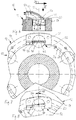
- a solid bowl centrifuge 10 whose centrifuge drum 12 with its end wall 14.
- One of several outflow openings 16 projecting axially through the end wall 14 in the direction of a longitudinal axis 18 of the centrifuge drum 12 is illustrated on the end wall 14.
- a weir plate 20 is attached to the end wall 14 in a stationary but adjustable manner.
- the weir plate 20 protrudes in front of the outflow opening 16, so that it covers the outside on its radially outer region.
- the weir plate 20 has a weir edge 22 on its radially inward edge.
- the weir edge 22 according to the prior art extends along the end wall 14 and thus transversely to the longitudinal axis 18 or at an angle of 90 ° to it.
- the weir edge 22 retains clarified material 24 in the centrifuge drum 12, so that during operation of the solid-bowl screw centrifuge 10, this clarified material 24 accumulates there with a pond depth 26 and subsequently flows largely continuously over the weir edge 22.
- An energy recovery device 28 is located on the outside of the weir plate 20 in the flow direction of the clarified material 24 behind or downstream of the weir edge 22.
- This energy recovery device 28 is designed as an outflow channel 30 which has a flat bottom surface 32 which extends tangentially at the height of the weir edge 22.
- a deflection surface 34 extends perpendicularly to the bottom surface 32 as part of the outflow channel 30 and, in accordance with the prior art, extends in an arc in front of the region of the outflow opening 16 which is open in the longitudinal direction.
- the deflection surface 34 deflects the clarified material 24, which flows axially inward through the outflow opening 16, radially inward under the weir edge 22 in an inflow direction 38, in a tangential direction to an outflow direction 40.
- the centrifuge drum 12 rotates in a direction of rotation 36 and the clarified material 24 is deflected by the deflecting surface 34 such that it emerges tangentially from the energy recovery device 28 against this direction of rotation 36.
- the clarified material 24 “pushes off” from the centrifuge drum 12, as a result of which it transmits part of its impulse to it and contributes to energy recovery on the centrifuge drum 12. This "pushing off” is alleviated by the internal fluid friction in the clarified material 24 and by the fact that the centrifuge drum 12 also continues to rotate in the direction of rotation 36.
- the centrifuge drum 12 thus partially evades the repulsion.
- FIG. 1 An embodiment of a solid bowl screw centrifuge 10 is illustrated with its centrifuge drum 12, on the weir plate 20 of which a weir edge 42 is provided in accordance with the invention.
- This weir edge 42 is pivoted with respect to the longitudinal axis 18 in its entire extent or length as a straight line by an angle 44 of 10 ° to the direction of rotation 36.
- the weir edge 42 therefore does not extend in the transverse direction, but instead points obliquely to the direction of rotation 36 on the outside.
- an outflow channel 46 In the direction of flow of the clarified material 24, behind the weir edge 42, there is an outflow channel 46 according to the invention, which is initially designed with a flat overflow surface 48 which is inclined radially outwards.
- the overflow surface 48 is inclined at an angle 50 of 45 ° to the longitudinal axis 18 of the centrifuge drum 12 and extends over the entire width of the weir edge 42.
- the overflow surface 48 is part of an energy recovery device 52 according to the invention and directs the outflow over the oblique weir edge 42 Good 24 slightly radially outwards and counter to the direction of rotation 36. This good 24 is accelerated with regard to its flow speed. Some of its potential energy is thus converted within the energy recovery device 52 to kinetic energy.
- the outflow channel 46 of the energy recovery device 52 also includes a flat bottom surface 54, which is somewhat more radially outward than the weir edge 42. Furthermore, an arcuate deflection surface 56 is also provided.
- the outflowing material 24 is slightly opposed by the overflow surface 48
- Direction of rotation 36 as explained above, is guided in a particularly accelerated manner against this deflection surface 56.
- the deflection surface 56 can be made particularly small and it is sufficient if it extends radially inward only to the depth of the weir edge 42. With such a small deflection surface 56, the energy recovery device 52 has a comparatively small flow resistance on the outside of the centrifuge drum 12, which is rotating at high speed.
- the 6 and 7 show a preferred embodiment of a weir edge 42 according to the invention with an energy recovery device 52 according to the invention, in which the weir edge 42 is oriented at an angle 44 of 20 ° to the longitudinal axis 18.
Landscapes
- Centrifugal Separators (AREA)
Claims (10)
- Centrifugeuse à vis sans fin à paroi pleine (10) comportant un tambour de centrifugeuse (12) mobile en rotation autour d'un axe longitudinal (18) dans une direction de rotation (36) pendant le fonctionnement, dont la face frontale présente au moins une ouverture d'évacuation (16) pour évacuer des produits clarifiés (24) hors du tambour (12), une arête de barrage (22, 42) qui délimite l'ouverture d'évacuation (16) radialement vers l'extérieur, et un moyen de récupération d'énergie (28, 52) situé sur l'arête de barrage (22, 42) pour récupérer l'énergie des produits clarifiés (24) en évacuation,
caractérisée en ce que
l'arête de barrage (42), vue depuis l'axe longitudinal (18), est disposée de façon pivotée au moins localement vers la direction de rotation (36) de sorte que le flux des produits (24) évacués derrière l'arête de barrage (22, 42) est tout d'abord encore déplacé dans la direction de rotation (36). - Centrifugeuse à vis sans fin à paroi pleine selon la revendication 1,
dans laquelle
l'arête de barrage (42) est disposée de façon pivotée au moins localement vers la direction de rotation (36) selon un angle d'environ 2° à 45°, de préférence entre 5° et 30°, de manière particulièrement préférée entre 10° et 15°. - Centrifugeuse à vis sans fin à paroi pleine selon la revendication 1 ou 2,
dans laquelle
l'arête de barrage (42) est disposée de façon pivotée dans son ensemble vers la direction de rotation (36). - Centrifugeuse à vis sans fin à paroi pleine selon l'une des revendications 1 à 3,
dans laquelle
en arrière de l'arête de barrage (42), vue en direction d'écoulement des produits (24) évacués par l'arête de barrage (42), une surface de déversement (48) pivotée radialement vers l'extérieur est réalisée pour les produits (24) en évacuation. - Centrifugeuse à vis sans fin à paroi pleine selon la revendication 4,
dans laquelle
la surface de déversement (48) s'étend le long de toute l'arête de barrage (42). - Centrifugeuse à vis sans fin à paroi pleine selon l'une des revendications 4 ou 5,
dans laquelle
la surface de déversement (48) est disposée de façon pivotée par rapport à l'axe longitudinal (18) radialement vers l'extérieur selon un angle compris entre 10° et 65°, de préférence entre 20° et 55°, de manière particulièrement préférée entre 30° et 45°. - Centrifugeuse à vis sans fin à paroi pleine selon l'une des revendications 1 à 6,
dans laquelle
le moyen de récupération d'énergie (52) est conçu avec une surface de déviation (56) qui fait dévier les produits évacués (24) en sens opposé à la direction de rotation (36). - Centrifugeuse à vis sans fin à paroi pleine selon la revendication 7,
dans laquelle
la surface de déviation (56) est disposée axialement derrière l'arête de barrage (42), vue en direction de l'axe longitudinal (18). - Centrifugeuse à vis sans fin à paroi pleine selon la revendication 7 ou 8,
dans laquelle
la surface de déviation (56) est disposée exclusivement radialement à l'extérieur de l'arête de barrage (42), vue en direction de l'axe longitudinal (18). - Centrifugeuse à vis sans fin à paroi pleine selon l'une des revendications 1 à 9,
dans laquelle
l'arête de barrage (42) et le moyen de récupération d'énergie (52) sont conçus sous la forme d'une unité structurelle déplaçable conjointement sur le tambour de centrifugeuse (12).
Applications Claiming Priority (2)
| Application Number | Priority Date | Filing Date | Title |
|---|---|---|---|
| DE102013001436.0A DE102013001436A1 (de) | 2013-01-29 | 2013-01-29 | Vollmantelschneckenzentrifuge mit einer Wehrkante |
| PCT/DE2013/100379 WO2014117760A1 (fr) | 2013-01-29 | 2013-11-08 | Centrifugeuse à vis à bol plein dotée d'un bord faisant barrage |
Publications (2)
| Publication Number | Publication Date |
|---|---|
| EP2950932A1 EP2950932A1 (fr) | 2015-12-09 |
| EP2950932B1 true EP2950932B1 (fr) | 2020-01-22 |
Family
ID=49724430
Family Applications (1)
| Application Number | Title | Priority Date | Filing Date |
|---|---|---|---|
| EP13801466.7A Active EP2950932B1 (fr) | 2013-01-29 | 2013-11-08 | Centrifugeuse à vis à bol plein dotée d'un bord faisant barrage |
Country Status (5)
| Country | Link |
|---|---|
| US (1) | US10105716B2 (fr) |
| EP (1) | EP2950932B1 (fr) |
| DE (1) | DE102013001436A1 (fr) |
| DK (1) | DK2950932T3 (fr) |
| WO (1) | WO2014117760A1 (fr) |
Families Citing this family (8)
| Publication number | Priority date | Publication date | Assignee | Title |
|---|---|---|---|---|
| EP2331264B1 (fr) * | 2008-08-15 | 2017-05-03 | M-I Llc | Centrifugeuse |
| DE102012106226A1 (de) * | 2012-07-11 | 2014-01-16 | Gea Mechanical Equipment Gmbh | Vollmantel-Schneckenzentrifuge mit Überlaufwehr |
| JP5220950B1 (ja) * | 2012-11-02 | 2013-06-26 | 巴工業株式会社 | 分離液噴射ノズル付き遠心分離機 |
| DE102013001436A1 (de) * | 2013-01-29 | 2014-07-31 | Flottweg Se | Vollmantelschneckenzentrifuge mit einer Wehrkante |
| EP2789395B2 (fr) * | 2013-04-08 | 2019-11-06 | Flottweg SE | Centrifugeuse à vis a bol plein dotée d'un dispositif de récupération d'énergie |
| DE102014101205B4 (de) * | 2014-01-31 | 2021-08-05 | Flottweg Se | Auslassvorrichtung einer Vollmantelschneckenzentrifuge |
| DE102014104296A1 (de) * | 2014-03-27 | 2015-10-01 | Flottweg Se | Auslassvorrichtung einer Vollmantelschneckenzentrifuge |
| DE102017130904B4 (de) * | 2017-12-21 | 2019-07-11 | Flottweg Se | Auslassvorrichtung einer Vollmantelschneckenzentrifuge mit einem Umlenkgerinne |
Family Cites Families (18)
| Publication number | Priority date | Publication date | Assignee | Title |
|---|---|---|---|---|
| US4575370A (en) * | 1984-11-15 | 1986-03-11 | Pennwalt Corporation | Centrifuge employing variable height discharge weir |
| DE3446166C2 (de) | 1984-12-18 | 1987-04-02 | Flottweg-Werk Bird Machine GmbH, 8313 Vilsbiburg | Einstellbare Wehrplatte für Vollmantel-Schneckenzentrifugen |
| DE3921327A1 (de) * | 1989-06-29 | 1991-01-03 | Kloeckner Humboldt Deutz Ag | Wehr zum einstellen des fluessigkeitsstandes in vollmantelzentrifugen |
| JP3543597B2 (ja) * | 1997-12-22 | 2004-07-14 | 株式会社クボタ | 横型遠心分離機における分離水の排出装置 |
| US7022061B2 (en) * | 2002-10-15 | 2006-04-04 | Andritz Ag | Centrifuge discharge port with power recovery |
| US20040072668A1 (en) * | 2002-10-15 | 2004-04-15 | Baker Hughes Incorporated | Liquid phase discharge port incorporating chamber nozzle device for centrifuge |
| EP2331264B1 (fr) * | 2008-08-15 | 2017-05-03 | M-I Llc | Centrifugeuse |
| DK200801846A (en) * | 2008-12-30 | 2010-07-01 | Alfa Laval Corp Ab | A decanter centrifuge with a slide valve body |
| DK200801848A (en) * | 2008-12-30 | 2010-07-01 | Alfa Laval Corp Ab | A decanter centrifuge and a decanter centrifuge discharge port memeber. |
| DE102010032503A1 (de) | 2010-07-28 | 2012-02-02 | Gea Mechanical Equipment Gmbh | Vollmantel-Schneckenzentrifuge mit Überlaufwehr |
| DK178253B1 (en) * | 2010-11-12 | 2015-10-12 | Alfa Laval Corp Ab | A centrifugal separator and an outlet element for a centrifugal separator |
| ES2606134T3 (es) * | 2011-07-29 | 2017-03-22 | Andritz S.A.S. | Centrifugador y miembro de orificio de descarga de centrifugador para reducción de potencia |
| DE102012106226A1 (de) * | 2012-07-11 | 2014-01-16 | Gea Mechanical Equipment Gmbh | Vollmantel-Schneckenzentrifuge mit Überlaufwehr |
| DE102012014563B4 (de) * | 2012-07-23 | 2014-12-11 | Flottweg Se | Vollmantelschneckenzentrifuge mit einer Energierückgewinnungseinrichtung |
| DE102013001436A1 (de) * | 2013-01-29 | 2014-07-31 | Flottweg Se | Vollmantelschneckenzentrifuge mit einer Wehrkante |
| EP2789395B2 (fr) * | 2013-04-08 | 2019-11-06 | Flottweg SE | Centrifugeuse à vis a bol plein dotée d'un dispositif de récupération d'énergie |
| DE102014101205B4 (de) * | 2014-01-31 | 2021-08-05 | Flottweg Se | Auslassvorrichtung einer Vollmantelschneckenzentrifuge |
| DE102014104296A1 (de) * | 2014-03-27 | 2015-10-01 | Flottweg Se | Auslassvorrichtung einer Vollmantelschneckenzentrifuge |
-
2013
- 2013-01-29 DE DE102013001436.0A patent/DE102013001436A1/de not_active Ceased
- 2013-11-08 WO PCT/DE2013/100379 patent/WO2014117760A1/fr not_active Ceased
- 2013-11-08 EP EP13801466.7A patent/EP2950932B1/fr active Active
- 2013-11-08 US US14/764,188 patent/US10105716B2/en active Active
- 2013-11-08 DK DK13801466.7T patent/DK2950932T3/da active
Non-Patent Citations (1)
| Title |
|---|
| None * |
Also Published As
| Publication number | Publication date |
|---|---|
| DK2950932T3 (da) | 2020-04-14 |
| US10105716B2 (en) | 2018-10-23 |
| EP2950932A1 (fr) | 2015-12-09 |
| DE102013001436A1 (de) | 2014-07-31 |
| US20150360240A1 (en) | 2015-12-17 |
| WO2014117760A1 (fr) | 2014-08-07 |
Similar Documents
| Publication | Publication Date | Title |
|---|---|---|
| EP2950932A1 (fr) | Centrifugeuse à vis à bol plein dotée d'un bord faisant barrage | |
| DE102014101205B4 (de) | Auslassvorrichtung einer Vollmantelschneckenzentrifuge | |
| EP3478389B1 (fr) | Filtre de retrolavage | |
| EP1488077A1 (fr) | Aube de turbine refroidie | |
| EP2872256B1 (fr) | Centrifugeuse à vis sans fin et à bol plein avec déversoir de débordement | |
| EP2789395B2 (fr) | Centrifugeuse à vis a bol plein dotée d'un dispositif de récupération d'énergie | |
| EP2874753B1 (fr) | Centrifugeuse à vis sans fin à bol plein munie d'un dispositif de récupération d'énergie | |
| EP2923769B1 (fr) | Dispositif d'évacuation et centrifugeuse à vis à bol plein | |
| DE19524276C2 (de) | Vorrichtung zum Entfernen von Abscheidegut aus in einem Gerinne strömender Flüssigkeit | |
| DE102012004544A1 (de) | Trommelzentrifuge mit einer Einlauf-Beschleunigungseinrichtung | |
| EP3959380B1 (fr) | Dispositif pour transporter et éjecter un produit en vrac ou de la neige | |
| EP2551019B1 (fr) | Centrifugeuse à vis a bol plein dotée d'un bord faisant barrage | |
| WO2007104455A1 (fr) | Centrifugeuse comportant un tube d'alimentation | |
| EP2551020A1 (fr) | Dispositif d'introduction d'une centrifugeuse | |
| DE2013499A1 (de) | Anordnung für einen Zyklonenabscheider mit einer Entleerungskammer | |
| DE1757368C3 (de) | Vollmantel-Schneckenzentrifuge | |
| DE2908277A1 (de) | Schleppkopf fuer saugbagger | |
| DE2026479C3 (de) | Kontinuierlich arbeitende Zentrifuge | |
| DE112017006579T5 (de) | Spültoilette | |
| DE2146022C2 (de) | Sortiereinrichtung für Fasersuspensionen | |
| DE1921411C3 (de) | Rückwärtsströmungsweiche | |
| EP3105045B1 (fr) | Séparateur à vis de pression | |
| DE102017130904B4 (de) | Auslassvorrichtung einer Vollmantelschneckenzentrifuge mit einem Umlenkgerinne | |
| DE3310711C2 (fr) | ||
| EP2524725A1 (fr) | Dispositif de suppression de produit à tamiser à partir dýun liquide |
Legal Events
| Date | Code | Title | Description |
|---|---|---|---|
| PUAI | Public reference made under article 153(3) epc to a published international application that has entered the european phase |
Free format text: ORIGINAL CODE: 0009012 |
|
| 17P | Request for examination filed |
Effective date: 20150812 |
|
| AK | Designated contracting states |
Kind code of ref document: A1 Designated state(s): AL AT BE BG CH CY CZ DE DK EE ES FI FR GB GR HR HU IE IS IT LI LT LU LV MC MK MT NL NO PL PT RO RS SE SI SK SM TR |
|
| AX | Request for extension of the european patent |
Extension state: BA ME |
|
| DAX | Request for extension of the european patent (deleted) | ||
| GRAP | Despatch of communication of intention to grant a patent |
Free format text: ORIGINAL CODE: EPIDOSNIGR1 |
|
| STAA | Information on the status of an ep patent application or granted ep patent |
Free format text: STATUS: GRANT OF PATENT IS INTENDED |
|
| INTG | Intention to grant announced |
Effective date: 20190924 |
|
| GRAS | Grant fee paid |
Free format text: ORIGINAL CODE: EPIDOSNIGR3 |
|
| GRAA | (expected) grant |
Free format text: ORIGINAL CODE: 0009210 |
|
| STAA | Information on the status of an ep patent application or granted ep patent |
Free format text: STATUS: THE PATENT HAS BEEN GRANTED |
|
| AK | Designated contracting states |
Kind code of ref document: B1 Designated state(s): AL AT BE BG CH CY CZ DE DK EE ES FI FR GB GR HR HU IE IS IT LI LT LU LV MC MK MT NL NO PL PT RO RS SE SI SK SM TR |
|
| REG | Reference to a national code |
Ref country code: GB Ref legal event code: FG4D Free format text: NOT ENGLISH |
|
| REG | Reference to a national code |
Ref country code: CH Ref legal event code: EP |
|
| REG | Reference to a national code |
Ref country code: DE Ref legal event code: R096 Ref document number: 502013014252 Country of ref document: DE |
|
| REG | Reference to a national code |
Ref country code: AT Ref legal event code: REF Ref document number: 1226583 Country of ref document: AT Kind code of ref document: T Effective date: 20200215 |
|
| REG | Reference to a national code |
Ref country code: IE Ref legal event code: FG4D Free format text: LANGUAGE OF EP DOCUMENT: GERMAN |
|
| REG | Reference to a national code |
Ref country code: DK Ref legal event code: T3 Effective date: 20200407 |
|
| REG | Reference to a national code |
Ref country code: SE Ref legal event code: TRGR |
|
| REG | Reference to a national code |
Ref country code: NL Ref legal event code: MP Effective date: 20200122 |
|
| REG | Reference to a national code |
Ref country code: LT Ref legal event code: MG4D |
|
| PG25 | Lapsed in a contracting state [announced via postgrant information from national office to epo] |
Ref country code: NL Free format text: LAPSE BECAUSE OF FAILURE TO SUBMIT A TRANSLATION OF THE DESCRIPTION OR TO PAY THE FEE WITHIN THE PRESCRIBED TIME-LIMIT Effective date: 20200122 Ref country code: RS Free format text: LAPSE BECAUSE OF FAILURE TO SUBMIT A TRANSLATION OF THE DESCRIPTION OR TO PAY THE FEE WITHIN THE PRESCRIBED TIME-LIMIT Effective date: 20200122 Ref country code: FI Free format text: LAPSE BECAUSE OF FAILURE TO SUBMIT A TRANSLATION OF THE DESCRIPTION OR TO PAY THE FEE WITHIN THE PRESCRIBED TIME-LIMIT Effective date: 20200122 Ref country code: PT Free format text: LAPSE BECAUSE OF FAILURE TO SUBMIT A TRANSLATION OF THE DESCRIPTION OR TO PAY THE FEE WITHIN THE PRESCRIBED TIME-LIMIT Effective date: 20200614 Ref country code: NO Free format text: LAPSE BECAUSE OF FAILURE TO SUBMIT A TRANSLATION OF THE DESCRIPTION OR TO PAY THE FEE WITHIN THE PRESCRIBED TIME-LIMIT Effective date: 20200422 |
|
| PG25 | Lapsed in a contracting state [announced via postgrant information from national office to epo] |
Ref country code: IS Free format text: LAPSE BECAUSE OF FAILURE TO SUBMIT A TRANSLATION OF THE DESCRIPTION OR TO PAY THE FEE WITHIN THE PRESCRIBED TIME-LIMIT Effective date: 20200522 Ref country code: BG Free format text: LAPSE BECAUSE OF FAILURE TO SUBMIT A TRANSLATION OF THE DESCRIPTION OR TO PAY THE FEE WITHIN THE PRESCRIBED TIME-LIMIT Effective date: 20200422 Ref country code: LV Free format text: LAPSE BECAUSE OF FAILURE TO SUBMIT A TRANSLATION OF THE DESCRIPTION OR TO PAY THE FEE WITHIN THE PRESCRIBED TIME-LIMIT Effective date: 20200122 Ref country code: GR Free format text: LAPSE BECAUSE OF FAILURE TO SUBMIT A TRANSLATION OF THE DESCRIPTION OR TO PAY THE FEE WITHIN THE PRESCRIBED TIME-LIMIT Effective date: 20200423 Ref country code: HR Free format text: LAPSE BECAUSE OF FAILURE TO SUBMIT A TRANSLATION OF THE DESCRIPTION OR TO PAY THE FEE WITHIN THE PRESCRIBED TIME-LIMIT Effective date: 20200122 |
|
| REG | Reference to a national code |
Ref country code: DE Ref legal event code: R097 Ref document number: 502013014252 Country of ref document: DE |
|
| PG25 | Lapsed in a contracting state [announced via postgrant information from national office to epo] |
Ref country code: RO Free format text: LAPSE BECAUSE OF FAILURE TO SUBMIT A TRANSLATION OF THE DESCRIPTION OR TO PAY THE FEE WITHIN THE PRESCRIBED TIME-LIMIT Effective date: 20200122 Ref country code: ES Free format text: LAPSE BECAUSE OF FAILURE TO SUBMIT A TRANSLATION OF THE DESCRIPTION OR TO PAY THE FEE WITHIN THE PRESCRIBED TIME-LIMIT Effective date: 20200122 Ref country code: SM Free format text: LAPSE BECAUSE OF FAILURE TO SUBMIT A TRANSLATION OF THE DESCRIPTION OR TO PAY THE FEE WITHIN THE PRESCRIBED TIME-LIMIT Effective date: 20200122 Ref country code: LT Free format text: LAPSE BECAUSE OF FAILURE TO SUBMIT A TRANSLATION OF THE DESCRIPTION OR TO PAY THE FEE WITHIN THE PRESCRIBED TIME-LIMIT Effective date: 20200122 Ref country code: EE Free format text: LAPSE BECAUSE OF FAILURE TO SUBMIT A TRANSLATION OF THE DESCRIPTION OR TO PAY THE FEE WITHIN THE PRESCRIBED TIME-LIMIT Effective date: 20200122 Ref country code: SK Free format text: LAPSE BECAUSE OF FAILURE TO SUBMIT A TRANSLATION OF THE DESCRIPTION OR TO PAY THE FEE WITHIN THE PRESCRIBED TIME-LIMIT Effective date: 20200122 Ref country code: CZ Free format text: LAPSE BECAUSE OF FAILURE TO SUBMIT A TRANSLATION OF THE DESCRIPTION OR TO PAY THE FEE WITHIN THE PRESCRIBED TIME-LIMIT Effective date: 20200122 |
|
| PLBE | No opposition filed within time limit |
Free format text: ORIGINAL CODE: 0009261 |
|
| STAA | Information on the status of an ep patent application or granted ep patent |
Free format text: STATUS: NO OPPOSITION FILED WITHIN TIME LIMIT |
|
| 26N | No opposition filed |
Effective date: 20201023 |
|
| PG25 | Lapsed in a contracting state [announced via postgrant information from national office to epo] |
Ref country code: SI Free format text: LAPSE BECAUSE OF FAILURE TO SUBMIT A TRANSLATION OF THE DESCRIPTION OR TO PAY THE FEE WITHIN THE PRESCRIBED TIME-LIMIT Effective date: 20200122 Ref country code: PL Free format text: LAPSE BECAUSE OF FAILURE TO SUBMIT A TRANSLATION OF THE DESCRIPTION OR TO PAY THE FEE WITHIN THE PRESCRIBED TIME-LIMIT Effective date: 20200122 |
|
| PG25 | Lapsed in a contracting state [announced via postgrant information from national office to epo] |
Ref country code: MC Free format text: LAPSE BECAUSE OF FAILURE TO SUBMIT A TRANSLATION OF THE DESCRIPTION OR TO PAY THE FEE WITHIN THE PRESCRIBED TIME-LIMIT Effective date: 20200122 |
|
| REG | Reference to a national code |
Ref country code: CH Ref legal event code: PL |
|
| GBPC | Gb: european patent ceased through non-payment of renewal fee |
Effective date: 20201108 |
|
| PG25 | Lapsed in a contracting state [announced via postgrant information from national office to epo] |
Ref country code: LU Free format text: LAPSE BECAUSE OF NON-PAYMENT OF DUE FEES Effective date: 20201108 |
|
| REG | Reference to a national code |
Ref country code: BE Ref legal event code: MM Effective date: 20201130 |
|
| PG25 | Lapsed in a contracting state [announced via postgrant information from national office to epo] |
Ref country code: CH Free format text: LAPSE BECAUSE OF NON-PAYMENT OF DUE FEES Effective date: 20201130 Ref country code: LI Free format text: LAPSE BECAUSE OF NON-PAYMENT OF DUE FEES Effective date: 20201130 |
|
| PG25 | Lapsed in a contracting state [announced via postgrant information from national office to epo] |
Ref country code: IE Free format text: LAPSE BECAUSE OF NON-PAYMENT OF DUE FEES Effective date: 20201108 |
|
| PG25 | Lapsed in a contracting state [announced via postgrant information from national office to epo] |
Ref country code: GB Free format text: LAPSE BECAUSE OF NON-PAYMENT OF DUE FEES Effective date: 20201108 |
|
| PG25 | Lapsed in a contracting state [announced via postgrant information from national office to epo] |
Ref country code: MT Free format text: LAPSE BECAUSE OF FAILURE TO SUBMIT A TRANSLATION OF THE DESCRIPTION OR TO PAY THE FEE WITHIN THE PRESCRIBED TIME-LIMIT Effective date: 20200122 Ref country code: CY Free format text: LAPSE BECAUSE OF FAILURE TO SUBMIT A TRANSLATION OF THE DESCRIPTION OR TO PAY THE FEE WITHIN THE PRESCRIBED TIME-LIMIT Effective date: 20200122 |
|
| PG25 | Lapsed in a contracting state [announced via postgrant information from national office to epo] |
Ref country code: MK Free format text: LAPSE BECAUSE OF FAILURE TO SUBMIT A TRANSLATION OF THE DESCRIPTION OR TO PAY THE FEE WITHIN THE PRESCRIBED TIME-LIMIT Effective date: 20200122 Ref country code: AL Free format text: LAPSE BECAUSE OF FAILURE TO SUBMIT A TRANSLATION OF THE DESCRIPTION OR TO PAY THE FEE WITHIN THE PRESCRIBED TIME-LIMIT Effective date: 20200122 |
|
| PG25 | Lapsed in a contracting state [announced via postgrant information from national office to epo] |
Ref country code: BE Free format text: LAPSE BECAUSE OF NON-PAYMENT OF DUE FEES Effective date: 20201130 |
|
| P01 | Opt-out of the competence of the unified patent court (upc) registered |
Effective date: 20230531 |
|
| PGFP | Annual fee paid to national office [announced via postgrant information from national office to epo] |
Ref country code: DE Payment date: 20251128 Year of fee payment: 13 |
|
| PGFP | Annual fee paid to national office [announced via postgrant information from national office to epo] |
Ref country code: AT Payment date: 20251118 Year of fee payment: 13 |
|
| PGFP | Annual fee paid to national office [announced via postgrant information from national office to epo] |
Ref country code: IT Payment date: 20251121 Year of fee payment: 13 Ref country code: DK Payment date: 20251124 Year of fee payment: 13 |
|
| PGFP | Annual fee paid to national office [announced via postgrant information from national office to epo] |
Ref country code: FR Payment date: 20251124 Year of fee payment: 13 |
|
| PGFP | Annual fee paid to national office [announced via postgrant information from national office to epo] |
Ref country code: TR Payment date: 20251020 Year of fee payment: 13 |
|
| PGFP | Annual fee paid to national office [announced via postgrant information from national office to epo] |
Ref country code: SE Payment date: 20251124 Year of fee payment: 13 |