EP2586569A2 - Klemmbackenwerkzeug für ein mobiles Elektrowerkzeug mit Rotationsmotor - Google Patents
Klemmbackenwerkzeug für ein mobiles Elektrowerkzeug mit Rotationsmotor Download PDFInfo
- Publication number
- EP2586569A2 EP2586569A2 EP12189689.8A EP12189689A EP2586569A2 EP 2586569 A2 EP2586569 A2 EP 2586569A2 EP 12189689 A EP12189689 A EP 12189689A EP 2586569 A2 EP2586569 A2 EP 2586569A2
- Authority
- EP
- European Patent Office
- Prior art keywords
- tool
- jaws
- jaw
- input shaft
- power tool
- Prior art date
- Legal status (The legal status is an assumption and is not a legal conclusion. Google has not performed a legal analysis and makes no representation as to the accuracy of the status listed.)
- Granted
Links
Images



Classifications
-
- B—PERFORMING OPERATIONS; TRANSPORTING
- B25—HAND TOOLS; PORTABLE POWER-DRIVEN TOOLS; MANIPULATORS
- B25B—TOOLS OR BENCH DEVICES NOT OTHERWISE PROVIDED FOR, FOR FASTENING, CONNECTING, DISENGAGING, OR HOLDING
- B25B27/00—Hand tools, specially adapted for fitting together or separating parts or objects whether or not involving some deformation, not otherwise provided for
- B25B27/02—Hand tools, specially adapted for fitting together or separating parts or objects whether or not involving some deformation, not otherwise provided for for connecting objects by press fit or detaching same
- B25B27/10—Hand tools, specially adapted for fitting together or separating parts or objects whether or not involving some deformation, not otherwise provided for for connecting objects by press fit or detaching same inserting fittings into hoses
-
- B—PERFORMING OPERATIONS; TRANSPORTING
- B23—MACHINE TOOLS; METAL-WORKING NOT OTHERWISE PROVIDED FOR
- B23B—TURNING; BORING
- B23B45/00—Hand-held or like portable drilling machines, e.g. drill guns; Equipment therefor
- B23B45/003—Attachments
-
- B—PERFORMING OPERATIONS; TRANSPORTING
- B25—HAND TOOLS; PORTABLE POWER-DRIVEN TOOLS; MANIPULATORS
- B25B—TOOLS OR BENCH DEVICES NOT OTHERWISE PROVIDED FOR, FOR FASTENING, CONNECTING, DISENGAGING, OR HOLDING
- B25B21/00—Portable power-driven screw or nut setting or loosening tools; Attachments for drilling apparatus serving the same purpose
-
- B—PERFORMING OPERATIONS; TRANSPORTING
- B25—HAND TOOLS; PORTABLE POWER-DRIVEN TOOLS; MANIPULATORS
- B25B—TOOLS OR BENCH DEVICES NOT OTHERWISE PROVIDED FOR, FOR FASTENING, CONNECTING, DISENGAGING, OR HOLDING
- B25B27/00—Hand tools, specially adapted for fitting together or separating parts or objects whether or not involving some deformation, not otherwise provided for
- B25B27/14—Hand tools, specially adapted for fitting together or separating parts or objects whether or not involving some deformation, not otherwise provided for for assembling objects other than by press fit or detaching same
- B25B27/146—Clip clamping hand tools
-
- B—PERFORMING OPERATIONS; TRANSPORTING
- B25—HAND TOOLS; PORTABLE POWER-DRIVEN TOOLS; MANIPULATORS
- B25B—TOOLS OR BENCH DEVICES NOT OTHERWISE PROVIDED FOR, FOR FASTENING, CONNECTING, DISENGAGING, OR HOLDING
- B25B7/00—Pliers; Other hand-held gripping tools with jaws on pivoted limbs; Details applicable generally to pivoted-limb hand tools
- B25B7/12—Pliers; Other hand-held gripping tools with jaws on pivoted limbs; Details applicable generally to pivoted-limb hand tools involving special transmission means between the handles and the jaws, e.g. toggle levers, gears
-
- B—PERFORMING OPERATIONS; TRANSPORTING
- B25—HAND TOOLS; PORTABLE POWER-DRIVEN TOOLS; MANIPULATORS
- B25F—COMBINATION OR MULTI-PURPOSE TOOLS NOT OTHERWISE PROVIDED FOR; DETAILS OR COMPONENTS OF PORTABLE POWER-DRIVEN TOOLS NOT PARTICULARLY RELATED TO THE OPERATIONS PERFORMED AND NOT OTHERWISE PROVIDED FOR
- B25F3/00—Associations of tools for different working operations with one portable power-drive means; Adapters therefor
Definitions
- the invention relates to a jaw tool adapted to be mounted on a power tool rotary motor, for example on a drill.
- the object of the invention is to provide a jaw tool adapted to be mounted on a power tool rotary motor.
- the object of the invention is achieved with a jaw tool adapted to be mounted on a power tool rotary motor comprising a mandrel adapted to receive an input shaft of the jaw tool.
- the jaw tool comprises a body inside which are housed an end of the input shaft, an end of each of two jaws and a transmission mechanism adapted to transform the rotation of the jaw.
- input shaft in a relative pivoting of at least one of the two jaws relative to the other between an open position and a closed position of the jaws, and fastening means adapted to connect the body of the jaw tool to the power tool so as to prevent any rotation of the body relative to the power tool.
- the jaw tool can be an accessory adapted to transform for example a cordless drill or screwdriver into a crimping tool, stapler or clamping tool.
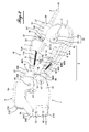
- the figure 1 schematically represents the arrangement of a tool of the invention with respect to a power tool on which it is mounted
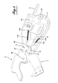
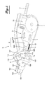
- the figure 2 represents the internal arrangement of a tool according to a first embodiment of the invention in the closed position of the tool
- the figure 3 represents the tool of the figure 2 in a perspective view on the outside of the body of the tool
- the figure 4 represents the tool of the figure 2 in the open position of the tool
- the figure 5 represents the internal arrangement of a tool according to a second embodiment of the invention in the closed position of the tool
- the figure 6 represents the interior layout of the tool of the figure 4 in the open position of the tool.
- the figure 1 schematically represents a jaw tool M, here a crimping tool, mounted on a cordless electric drill E.
- the crimping tool M comprises a body 1 having at one of its two opposite ends an input axis 2 and at its ends. other end two jaws 3, 4 shaped for crimping profiles.
- the jaws 3, 4 are actuated by the input shaft 2.
- the electric drill E comprises a mandrel T in which is fixed the input shaft 2 of the crimping tool M, and a handle P and a power supply box BA with a rechargeable battery BB.
- the tool M is fixed on the drill E by fastening means 6 comprising a clamping frame 61 and two arms 62, 63 connecting the clamping frame 61 to the body 1 of the jaw tool M.
- the clamping frame 61 is formed by two flanges arranged parallel to each other and spaced from each other to receive between them the power supply box BA, and two threaded rods with nuts 611, for example wing nuts, connecting the flanges together at their ends and for tightening the frame 61 on the housing BA.
- the clamping frame 61 can also be made in any other way, for example in one piece and with screws passing through the parts of the frame and resting on the housing BA or on the rechargeable battery BB.
- the Figures 2 to 4 respectively represent the interior layout ( figures 2 and 4 ) and the external arrangement ( figure 3 ) of a crimping tool M as a first embodiment of the invention.
- the tool M comprises, besides the input axis 2 and the jaws 3, 4 protruding opposite ends of the body 1, a transmission mechanism 5 connecting the input axis 2 to the jaws 3, 4 and transforming the rotation of the input axis 2 into a pivoting of the two jaws 3, 4 one relative to each other between an open position and a closed position of the jaws.
- the input shaft 2 which has two opposite ends 21, 22, axially passes through a worm 23 and is integral in rotation therewith.
- the input shaft 2 is housed by the first end 21, together with the worm 23, in the body 1 while the second end 22 is intended to be introduced into the mandrel T of the drill E.
- the input shaft 2 and the worm 23 are housed in the body 1 by two bearings 24, 25 housed inside the body 1 between flanges 26, 27 fixed to the body 1 by screws or rivets 18 19.
- the gear wheel 7 comprises on each of its two opposite faces and close to its periphery, a protrusion 72 fulfilling the function of a cam.
- the two protuberances 72 are formed as rollers 721 mounted on a common axis 722 disposed parallel to the axis 71 of the gear wheel 7 and passing therethrough.
- the toothed wheel 7 is followed by a pusher 8 having, on the side facing the toothed wheel 7, two arms 81A, 81B extending in planes parallel to each other. 1 and other spaced apart from each other and having concave ends 82 on which the rollers 721 bear cyclically at the rate dictated by the rotation of the gear wheel 7.
- Each of the arms 81A, 81B is provided with two oblong holes 811A , 811B in which are engaged pins (not shown) disposed on the two opposite inner faces of the body 1 or two rods passing through the body 1 and housed in holes 16, 17 ( figure 3 ), which provide a displacement in translation of the pusher 8 in the direction of the length of the body 1.
- the pusher 8 further comprises two oblique portions 83A, 83B extending the arms 81A, 81B and bringing them back to a median plane of part and side. the other of which the pusher 8 ends on portions 84A, 84B traversed by an axis 85 disposed transversely to said median plane.
- the axis 85 and the axes indicated in the paragraph below are represented by the orifices in which they are placed.
- the pusher 8 is connected to the jaws 3, 4 by two pairs of rods 9, 10 mounted on either side of the pusher by one of their opposite ends on the axis 85 of the pusher 8 and the other of their ends on the axes 37, 47 respectively of the jaw 3 and the jaw 4.
- the two jaws 3, 4 are pivotally mounted about a common axis 36 disposed inside the body 1.
- the jaw 3 is a piece having a U-shaped cross-section and thus having two central portions 31A, 31B connected to each other by a back 35.
- the two parts 31A, 31B extend in parallel planes one to the other and spaced from each other and form by their free ends 34A, 34B a matrix in which engages, in the closed position of the jaws 3, 4, a crimping punch 44.
- the two central portions 31A, 31B are extended by pivot portions 32A, 32B by which the jaw 3 is mounted on the axis 36 and which are followed by control arms 33A, 33B extending the central portions. 31A, 31B beyond the axis 36.
- the free ends of the control arms 33A, 33B of the jaw 3 are connected to the rods 9 controlling the pivoting of the jaw 3, by the axis 37.
- the jaw 4 is an L-shaped part with a forked working part having two parallel cheeks 41A, 41B between which the crimping punch 44 is removably fixed, for example by screws engaged in tapped holes 45 46.
- the jaw 4 further comprises an angular portion 42 to which are attached the rods 10 by means of the axis 47 and a control arm 43 by which the jaw 4 is mounted, together with the jaw 3, on the common axis 36. The pivoting of the jaw 4 is controlled by the rods 10.
- control arms 33A, 33B, 43 and the two pairs of connecting rods 9, 10 are connected to each other on either side of the pusher 8 so as to form quadrilaterals with variable geometry as a function of the momentary position of the pusher 8 and the position of the jaws 3, 4 which follows.
- the jaws 3, 4 are held in the open position by the pusher 8 pulled to the right (on the figure 4 ) by two return springs 11A, 11B fixed on ears 86A, 86B of the pusher 8 and anchoring points 12A, 12B formed inside the body 1.
- the axes 37, 85 and 47 are guided by oblong holes 13, 14 and 15 formed in the body 1, namely the axis 37 is guided by the oblong hole curve 13, the axis 85 is guided by the right oblong hole 14 and the axis 47 is guided by the oblong hole curve 15.
- the figures 5 and 6 represent the interior arrangement of an N stapler as a second embodiment of the invention.
- the tool is shown in the closed position on the figure 5 and in the open position on the figure 6 .
- the internal arrangement of the stapler N corresponds for the most part to the internal arrangement of the tool For this reason, the elements of the stapler N which are identical or correspond to elements of the crimping tool M bear the same reference numbers as the latter.
- the stapler N comprises, in addition to the input shaft 2 and the jaws 103, 104 protruding on opposite sides of the body 1, a transmission mechanism 5 connecting the input axis 2 to the jaws 103, 104 and transforming the rotation of the input shaft 2 in a pivoting of the two jaws 103, 104 relative to each other between an open position and a closed position of the jaws.
- the input shaft 2 is housed by the first of its two opposite ends 21, 22 in the body 1 and is provided with a worm 23 integral in rotation with the input shaft 2.
- the second end 22 is intended to be introduced into the mandrel T of the drill E.
- the toothed wheel 7 comprises on each of its two opposite faces and close to its periphery, an outgrowth 72 fulfilling the function of a cam.
- the two protuberances 72 are formed as rollers 721 mounted on an axis 722 disposed parallel to the axis 71 of the gear wheel 7 and passing therethrough.
- the toothed wheel 7 is followed by a pusher 8 having, on the side facing the toothed wheel 7, two arms 81A, 81B extending in planes parallel to each other. 1 and other spaced apart and having concave ends 82 on which the rollers 721 act cyclically at the rate dictated by the rotation of the toothed wheel 7.
- the pusher 8 further comprises two oblique portions 83A, 83B extending the arm 81A, 81B and bringing them back to a median plane on either side of which the pusher 8 ends on portions 84A, 84B traversed by an axis 185 arranged transversely mid-plane audit.
- the pusher 8 is connected to the jaws 103, 104 by two pairs of rods 9, 10 mounted by one of their opposite ends on the axis 185 of the pusher 8 and the other of their ends on pins 137, 147 respectively of the jaw 103 and the jaw 104.
- the two jaws 103, 104 are mounted pivoting about a common axis 136 held inside the body 1 by two plates 101, 102 completing the body 1.
- the jaws 103 and 104 have free ends in the shape of a bird's beak adapted to the shape of the staples for which the staple tool is designed.
- the two jaws 103, 104 and the two pairs of connecting rods 9, 10 are interconnected so as to form a quadrilateral with variable geometry as a function of the momentary position of the pusher 8 and the position of the jaws 103, 104 which follows.
- the jaws 103, 104 are held in the open position by the pusher 8 pulled to the right (on the figure 6 ) by a return spring 11 fixed on ears 186 of the pusher 8 and an anchor point 12 formed inside the body 1.
Landscapes
- Engineering & Computer Science (AREA)
- Mechanical Engineering (AREA)
- Perforating, Stamping-Out Or Severing By Means Other Than Cutting (AREA)
- Portable Nailing Machines And Staplers (AREA)
- Percussive Tools And Related Accessories (AREA)
- Manufacturing Of Electrical Connectors (AREA)
Applications Claiming Priority (1)
| Application Number | Priority Date | Filing Date | Title |
|---|---|---|---|
| FR1159773A FR2981873B1 (fr) | 2011-10-27 | 2011-10-27 | Outil a machoires pour un outil electroportatif a moteur rotatif |
Publications (3)
| Publication Number | Publication Date |
|---|---|
| EP2586569A2 true EP2586569A2 (de) | 2013-05-01 |
| EP2586569A3 EP2586569A3 (de) | 2017-05-31 |
| EP2586569B1 EP2586569B1 (de) | 2018-12-26 |
Family
ID=47040594
Family Applications (1)
| Application Number | Title | Priority Date | Filing Date |
|---|---|---|---|
| EP12189689.8A Active EP2586569B1 (de) | 2011-10-27 | 2012-10-24 | Klemmbackenwerkzeug für ein mobiles Elektrowerkzeug mit Rotationsmotor |
Country Status (3)
| Country | Link |
|---|---|
| EP (1) | EP2586569B1 (de) |
| DK (1) | DK2586569T3 (de) |
| FR (1) | FR2981873B1 (de) |
Cited By (4)
| Publication number | Priority date | Publication date | Assignee | Title |
|---|---|---|---|---|
| JP2020131298A (ja) * | 2019-02-13 | 2020-08-31 | 株式会社西田製作所 | 工具ヘッド |
| US11236849B2 (en) | 2019-09-04 | 2022-02-01 | Techtronic Cordless Gp | Pressing tool and method for a re-pressing operation |
| EP4074461A1 (de) * | 2021-04-16 | 2022-10-19 | Black & Decker, Inc. | Elektrowerkzeugzubehörsystem mit stütze |
| US20240066676A1 (en) * | 2021-04-16 | 2024-02-29 | Black & Decker Inc. | Power tool accessory system with brace |
Families Citing this family (5)
| Publication number | Priority date | Publication date | Assignee | Title |
|---|---|---|---|---|
| US9701032B2 (en) * | 2014-07-23 | 2017-07-11 | Black & Decker Inc. | Power tool accessory with brace |
| US12011820B2 (en) | 2020-02-04 | 2024-06-18 | Black & Decker Inc. | Power tool and tool bit holding system |
| USD951741S1 (en) | 2020-10-14 | 2022-05-17 | Simpson Strong-Tie Company Inc. | Screw driving tool |
| USD951050S1 (en) | 2020-10-14 | 2022-05-10 | Simpson Strong-Tie Company Inc. | Fastener driving tool adapter |
| US12365066B2 (en) | 2020-10-14 | 2025-07-22 | Simpson Strong-Tie Company Inc. | Fastener installation systems and adapters |
Family Cites Families (3)
| Publication number | Priority date | Publication date | Assignee | Title |
|---|---|---|---|---|
| US6138346A (en) * | 1998-12-21 | 2000-10-31 | Connectool Inc. | Portable hand-held battery-powered crimping tool |
| JP2001315069A (ja) * | 2000-05-01 | 2001-11-13 | Kiyoshi Doi | 回転動力器を用いた工具 |
| US6662620B1 (en) * | 2000-09-12 | 2003-12-16 | Black & Decker Inc. | Steel stud crimper |
-
2011
- 2011-10-27 FR FR1159773A patent/FR2981873B1/fr not_active Expired - Fee Related
-
2012
- 2012-10-24 EP EP12189689.8A patent/EP2586569B1/de active Active
- 2012-10-24 DK DK12189689.8T patent/DK2586569T3/en active
Non-Patent Citations (1)
| Title |
|---|
| None |
Cited By (5)
| Publication number | Priority date | Publication date | Assignee | Title |
|---|---|---|---|---|
| JP2020131298A (ja) * | 2019-02-13 | 2020-08-31 | 株式会社西田製作所 | 工具ヘッド |
| US11236849B2 (en) | 2019-09-04 | 2022-02-01 | Techtronic Cordless Gp | Pressing tool and method for a re-pressing operation |
| EP4074461A1 (de) * | 2021-04-16 | 2022-10-19 | Black & Decker, Inc. | Elektrowerkzeugzubehörsystem mit stütze |
| US20220331942A1 (en) * | 2021-04-16 | 2022-10-20 | Black & Decker Inc. | Power tool accessory system with brace |
| US20240066676A1 (en) * | 2021-04-16 | 2024-02-29 | Black & Decker Inc. | Power tool accessory system with brace |
Also Published As
| Publication number | Publication date |
|---|---|
| DK2586569T3 (en) | 2019-02-25 |
| EP2586569A3 (de) | 2017-05-31 |
| EP2586569B1 (de) | 2018-12-26 |
| FR2981873A1 (fr) | 2013-05-03 |
| FR2981873B1 (fr) | 2015-03-27 |
Similar Documents
| Publication | Publication Date | Title |
|---|---|---|
| EP2586569B1 (de) | Klemmbackenwerkzeug für ein mobiles Elektrowerkzeug mit Rotationsmotor | |
| US10745158B2 (en) | Strapping tensioning and sealing tool | |
| US20240294286A1 (en) | Strapping Tensioning And Sealing Tool | |
| FR3000417A3 (fr) | Cle a choc electrique | |
| FR2615771A1 (fr) | Coupe-cable a main | |
| FR2998501A3 (fr) | Mecanisme de serrage pour accessoires et outil electrique comportant celui-ci | |
| WO2021243090A1 (en) | Strapping tool | |
| TW201718184A (zh) | 手壓鉗 | |
| FR3023865A1 (fr) | Ensemble de poignee pour vehicule automobile et ouvrant comprenant un tel ensemble de poignee | |
| WO2002066208A1 (fr) | Porte-brucelles | |
| FR2581913A1 (fr) | Systeme a cliquet selectivement verrouillable pour outils portatifs, en particulier outils electriques alimentes par batterie | |
| EP2995386B1 (de) | Vorrichtung zur festen verbindung eines kleber-applikators auf einer motorbetriebenen bohr- oder schraubmaschine | |
| FR2463656A1 (fr) | Dispositif de cisaillement tel que coupe-boulons | |
| US7347125B1 (en) | Automatic adjustable head wrench | |
| FR2899725A1 (fr) | Bloc accumulateur pour l'alimentation d'appareils electriques | |
| CN103501972A (zh) | 动力切割工具 | |
| EP2325706A1 (de) | Vorrichtung zum Befestigen eines Armbands | |
| FR2515560A1 (fr) | Outil a rochet | |
| EP2569500B1 (de) | Beschlag für eine tür- oder fensteröffnung | |
| EP1702691A1 (de) | Vorrichtung zum Biegen und Ziehen | |
| GB2498829A (en) | Garden shears having a gear rotatable in a toothed slot | |
| FR2661314A1 (fr) | Canne telescopique a outil de coupe orientable et motorise. | |
| JP4411229B2 (ja) | 制動機構、および、可動体の支持機構 | |
| JP2000117656A (ja) | 手動圧縮工具 | |
| FR3136930A1 (fr) | Kit de pinces multifonctions pour sécateur motorisé électroportatif |
Legal Events
| Date | Code | Title | Description |
|---|---|---|---|
| PUAI | Public reference made under article 153(3) epc to a published international application that has entered the european phase |
Free format text: ORIGINAL CODE: 0009012 |
|
| AK | Designated contracting states |
Kind code of ref document: A2 Designated state(s): AL AT BE BG CH CY CZ DE DK EE ES FI FR GB GR HR HU IE IS IT LI LT LU LV MC MK MT NL NO PL PT RO RS SE SI SK SM TR |
|
| AX | Request for extension of the european patent |
Extension state: BA ME |
|
| PUAL | Search report despatched |
Free format text: ORIGINAL CODE: 0009013 |
|
| AK | Designated contracting states |
Kind code of ref document: A3 Designated state(s): AL AT BE BG CH CY CZ DE DK EE ES FI FR GB GR HR HU IE IS IT LI LT LU LV MC MK MT NL NO PL PT RO RS SE SI SK SM TR |
|
| AX | Request for extension of the european patent |
Extension state: BA ME |
|
| RIC1 | Information provided on ipc code assigned before grant |
Ipc: B23B 45/00 20060101ALI20170424BHEP Ipc: B25B 27/14 20060101ALI20170424BHEP Ipc: B25B 21/00 20060101ALI20170424BHEP Ipc: B21D 39/03 20060101ALI20170424BHEP Ipc: B25B 27/10 20060101ALI20170424BHEP Ipc: H01R 43/042 20060101ALI20170424BHEP Ipc: B25B 7/12 20060101AFI20170424BHEP Ipc: B25F 3/00 20060101ALI20170424BHEP |
|
| STAA | Information on the status of an ep patent application or granted ep patent |
Free format text: STATUS: REQUEST FOR EXAMINATION WAS MADE |
|
| 17P | Request for examination filed |
Effective date: 20171130 |
|
| RBV | Designated contracting states (corrected) |
Designated state(s): AL AT BE BG CH CY CZ DE DK EE ES FI FR GB GR HR HU IE IS IT LI LT LU LV MC MK MT NL NO PL PT RO RS SE SI SK SM TR |
|
| GRAP | Despatch of communication of intention to grant a patent |
Free format text: ORIGINAL CODE: EPIDOSNIGR1 |
|
| STAA | Information on the status of an ep patent application or granted ep patent |
Free format text: STATUS: GRANT OF PATENT IS INTENDED |
|
| INTG | Intention to grant announced |
Effective date: 20180817 |
|
| GRAS | Grant fee paid |
Free format text: ORIGINAL CODE: EPIDOSNIGR3 |
|
| GRAA | (expected) grant |
Free format text: ORIGINAL CODE: 0009210 |
|
| STAA | Information on the status of an ep patent application or granted ep patent |
Free format text: STATUS: THE PATENT HAS BEEN GRANTED |
|
| AK | Designated contracting states |
Kind code of ref document: B1 Designated state(s): AL AT BE BG CH CY CZ DE DK EE ES FI FR GB GR HR HU IE IS IT LI LT LU LV MC MK MT NL NO PL PT RO RS SE SI SK SM TR |
|
| REG | Reference to a national code |
Ref country code: GB Ref legal event code: FG4D Free format text: NOT ENGLISH |
|
| REG | Reference to a national code |
Ref country code: CH Ref legal event code: EP |
|
| REG | Reference to a national code |
Ref country code: AT Ref legal event code: REF Ref document number: 1080746 Country of ref document: AT Kind code of ref document: T Effective date: 20190115 |
|
| REG | Reference to a national code |
Ref country code: DE Ref legal event code: R096 Ref document number: 602012055072 Country of ref document: DE |
|
| REG | Reference to a national code |
Ref country code: IE Ref legal event code: FG4D Free format text: LANGUAGE OF EP DOCUMENT: FRENCH |
|
| REG | Reference to a national code |
Ref country code: DK Ref legal event code: T3 Effective date: 20190218 |
|
| REG | Reference to a national code |
Ref country code: NL Ref legal event code: FP |
|
| REG | Reference to a national code |
Ref country code: SE Ref legal event code: TRGR |
|
| REG | Reference to a national code |
Ref country code: CH Ref legal event code: PCAR Free format text: NEW ADDRESS: RUE DES NOYERS 11, 2000 NEUCHATEL (CH) |
|
| PG25 | Lapsed in a contracting state [announced via postgrant information from national office to epo] |
Ref country code: FI Free format text: LAPSE BECAUSE OF FAILURE TO SUBMIT A TRANSLATION OF THE DESCRIPTION OR TO PAY THE FEE WITHIN THE PRESCRIBED TIME-LIMIT Effective date: 20181226 Ref country code: LV Free format text: LAPSE BECAUSE OF FAILURE TO SUBMIT A TRANSLATION OF THE DESCRIPTION OR TO PAY THE FEE WITHIN THE PRESCRIBED TIME-LIMIT Effective date: 20181226 Ref country code: HR Free format text: LAPSE BECAUSE OF FAILURE TO SUBMIT A TRANSLATION OF THE DESCRIPTION OR TO PAY THE FEE WITHIN THE PRESCRIBED TIME-LIMIT Effective date: 20181226 Ref country code: LT Free format text: LAPSE BECAUSE OF FAILURE TO SUBMIT A TRANSLATION OF THE DESCRIPTION OR TO PAY THE FEE WITHIN THE PRESCRIBED TIME-LIMIT Effective date: 20181226 Ref country code: BG Free format text: LAPSE BECAUSE OF FAILURE TO SUBMIT A TRANSLATION OF THE DESCRIPTION OR TO PAY THE FEE WITHIN THE PRESCRIBED TIME-LIMIT Effective date: 20190326 Ref country code: NO Free format text: LAPSE BECAUSE OF FAILURE TO SUBMIT A TRANSLATION OF THE DESCRIPTION OR TO PAY THE FEE WITHIN THE PRESCRIBED TIME-LIMIT Effective date: 20190326 |
|
| REG | Reference to a national code |
Ref country code: LT Ref legal event code: MG4D |
|
| PG25 | Lapsed in a contracting state [announced via postgrant information from national office to epo] |
Ref country code: GR Free format text: LAPSE BECAUSE OF FAILURE TO SUBMIT A TRANSLATION OF THE DESCRIPTION OR TO PAY THE FEE WITHIN THE PRESCRIBED TIME-LIMIT Effective date: 20190327 Ref country code: RS Free format text: LAPSE BECAUSE OF FAILURE TO SUBMIT A TRANSLATION OF THE DESCRIPTION OR TO PAY THE FEE WITHIN THE PRESCRIBED TIME-LIMIT Effective date: 20181226 Ref country code: AL Free format text: LAPSE BECAUSE OF FAILURE TO SUBMIT A TRANSLATION OF THE DESCRIPTION OR TO PAY THE FEE WITHIN THE PRESCRIBED TIME-LIMIT Effective date: 20181226 |
|
| REG | Reference to a national code |
Ref country code: AT Ref legal event code: MK05 Ref document number: 1080746 Country of ref document: AT Kind code of ref document: T Effective date: 20181226 |
|
| PG25 | Lapsed in a contracting state [announced via postgrant information from national office to epo] |
Ref country code: IT Free format text: LAPSE BECAUSE OF FAILURE TO SUBMIT A TRANSLATION OF THE DESCRIPTION OR TO PAY THE FEE WITHIN THE PRESCRIBED TIME-LIMIT Effective date: 20181226 Ref country code: ES Free format text: LAPSE BECAUSE OF FAILURE TO SUBMIT A TRANSLATION OF THE DESCRIPTION OR TO PAY THE FEE WITHIN THE PRESCRIBED TIME-LIMIT Effective date: 20181226 Ref country code: CZ Free format text: LAPSE BECAUSE OF FAILURE TO SUBMIT A TRANSLATION OF THE DESCRIPTION OR TO PAY THE FEE WITHIN THE PRESCRIBED TIME-LIMIT Effective date: 20181226 Ref country code: PT Free format text: LAPSE BECAUSE OF FAILURE TO SUBMIT A TRANSLATION OF THE DESCRIPTION OR TO PAY THE FEE WITHIN THE PRESCRIBED TIME-LIMIT Effective date: 20190426 Ref country code: PL Free format text: LAPSE BECAUSE OF FAILURE TO SUBMIT A TRANSLATION OF THE DESCRIPTION OR TO PAY THE FEE WITHIN THE PRESCRIBED TIME-LIMIT Effective date: 20181226 |
|
| PG25 | Lapsed in a contracting state [announced via postgrant information from national office to epo] |
Ref country code: EE Free format text: LAPSE BECAUSE OF FAILURE TO SUBMIT A TRANSLATION OF THE DESCRIPTION OR TO PAY THE FEE WITHIN THE PRESCRIBED TIME-LIMIT Effective date: 20181226 Ref country code: SM Free format text: LAPSE BECAUSE OF FAILURE TO SUBMIT A TRANSLATION OF THE DESCRIPTION OR TO PAY THE FEE WITHIN THE PRESCRIBED TIME-LIMIT Effective date: 20181226 Ref country code: SK Free format text: LAPSE BECAUSE OF FAILURE TO SUBMIT A TRANSLATION OF THE DESCRIPTION OR TO PAY THE FEE WITHIN THE PRESCRIBED TIME-LIMIT Effective date: 20181226 Ref country code: RO Free format text: LAPSE BECAUSE OF FAILURE TO SUBMIT A TRANSLATION OF THE DESCRIPTION OR TO PAY THE FEE WITHIN THE PRESCRIBED TIME-LIMIT Effective date: 20181226 Ref country code: IS Free format text: LAPSE BECAUSE OF FAILURE TO SUBMIT A TRANSLATION OF THE DESCRIPTION OR TO PAY THE FEE WITHIN THE PRESCRIBED TIME-LIMIT Effective date: 20190426 |
|
| REG | Reference to a national code |
Ref country code: DE Ref legal event code: R097 Ref document number: 602012055072 Country of ref document: DE |
|
| PG25 | Lapsed in a contracting state [announced via postgrant information from national office to epo] |
Ref country code: AT Free format text: LAPSE BECAUSE OF FAILURE TO SUBMIT A TRANSLATION OF THE DESCRIPTION OR TO PAY THE FEE WITHIN THE PRESCRIBED TIME-LIMIT Effective date: 20181226 |
|
| PGFP | Annual fee paid to national office [announced via postgrant information from national office to epo] |
Ref country code: SE Payment date: 20190923 Year of fee payment: 8 Ref country code: IE Payment date: 20190920 Year of fee payment: 8 Ref country code: NL Payment date: 20190925 Year of fee payment: 8 |
|
| PLBE | No opposition filed within time limit |
Free format text: ORIGINAL CODE: 0009261 |
|
| STAA | Information on the status of an ep patent application or granted ep patent |
Free format text: STATUS: NO OPPOSITION FILED WITHIN TIME LIMIT |
|
| PGFP | Annual fee paid to national office [announced via postgrant information from national office to epo] |
Ref country code: BE Payment date: 20190923 Year of fee payment: 8 |
|
| 26N | No opposition filed |
Effective date: 20190927 |
|
| PGFP | Annual fee paid to national office [announced via postgrant information from national office to epo] |
Ref country code: GB Payment date: 20190923 Year of fee payment: 8 |
|
| PGFP | Annual fee paid to national office [announced via postgrant information from national office to epo] |
Ref country code: CH Payment date: 20190923 Year of fee payment: 8 Ref country code: DE Payment date: 20190918 Year of fee payment: 8 |
|
| PG25 | Lapsed in a contracting state [announced via postgrant information from national office to epo] |
Ref country code: SI Free format text: LAPSE BECAUSE OF FAILURE TO SUBMIT A TRANSLATION OF THE DESCRIPTION OR TO PAY THE FEE WITHIN THE PRESCRIBED TIME-LIMIT Effective date: 20181226 |
|
| PG25 | Lapsed in a contracting state [announced via postgrant information from national office to epo] |
Ref country code: TR Free format text: LAPSE BECAUSE OF FAILURE TO SUBMIT A TRANSLATION OF THE DESCRIPTION OR TO PAY THE FEE WITHIN THE PRESCRIBED TIME-LIMIT Effective date: 20181226 |
|
| PG25 | Lapsed in a contracting state [announced via postgrant information from national office to epo] |
Ref country code: MC Free format text: LAPSE BECAUSE OF FAILURE TO SUBMIT A TRANSLATION OF THE DESCRIPTION OR TO PAY THE FEE WITHIN THE PRESCRIBED TIME-LIMIT Effective date: 20181226 |
|
| PG25 | Lapsed in a contracting state [announced via postgrant information from national office to epo] |
Ref country code: LU Free format text: LAPSE BECAUSE OF NON-PAYMENT OF DUE FEES Effective date: 20191024 |
|
| REG | Reference to a national code |
Ref country code: DE Ref legal event code: R119 Ref document number: 602012055072 Country of ref document: DE |
|
| PG25 | Lapsed in a contracting state [announced via postgrant information from national office to epo] |
Ref country code: CY Free format text: LAPSE BECAUSE OF FAILURE TO SUBMIT A TRANSLATION OF THE DESCRIPTION OR TO PAY THE FEE WITHIN THE PRESCRIBED TIME-LIMIT Effective date: 20181226 |
|
| REG | Reference to a national code |
Ref country code: CH Ref legal event code: PL |
|
| REG | Reference to a national code |
Ref country code: SE Ref legal event code: EUG |
|
| REG | Reference to a national code |
Ref country code: NL Ref legal event code: MM Effective date: 20201101 |
|
| GBPC | Gb: european patent ceased through non-payment of renewal fee |
Effective date: 20201024 |
|
| REG | Reference to a national code |
Ref country code: BE Ref legal event code: MM Effective date: 20201031 |
|
| PG25 | Lapsed in a contracting state [announced via postgrant information from national office to epo] |
Ref country code: HU Free format text: LAPSE BECAUSE OF FAILURE TO SUBMIT A TRANSLATION OF THE DESCRIPTION OR TO PAY THE FEE WITHIN THE PRESCRIBED TIME-LIMIT; INVALID AB INITIO Effective date: 20121024 Ref country code: NL Free format text: LAPSE BECAUSE OF NON-PAYMENT OF DUE FEES Effective date: 20201101 Ref country code: MT Free format text: LAPSE BECAUSE OF FAILURE TO SUBMIT A TRANSLATION OF THE DESCRIPTION OR TO PAY THE FEE WITHIN THE PRESCRIBED TIME-LIMIT Effective date: 20181226 Ref country code: DE Free format text: LAPSE BECAUSE OF NON-PAYMENT OF DUE FEES Effective date: 20210501 |
|
| PG25 | Lapsed in a contracting state [announced via postgrant information from national office to epo] |
Ref country code: CH Free format text: LAPSE BECAUSE OF NON-PAYMENT OF DUE FEES Effective date: 20201031 Ref country code: BE Free format text: LAPSE BECAUSE OF NON-PAYMENT OF DUE FEES Effective date: 20201031 Ref country code: SE Free format text: LAPSE BECAUSE OF NON-PAYMENT OF DUE FEES Effective date: 20201025 Ref country code: LI Free format text: LAPSE BECAUSE OF NON-PAYMENT OF DUE FEES Effective date: 20201031 Ref country code: GB Free format text: LAPSE BECAUSE OF NON-PAYMENT OF DUE FEES Effective date: 20201024 |
|
| PG25 | Lapsed in a contracting state [announced via postgrant information from national office to epo] |
Ref country code: IE Free format text: LAPSE BECAUSE OF NON-PAYMENT OF DUE FEES Effective date: 20201024 |
|
| PGFP | Annual fee paid to national office [announced via postgrant information from national office to epo] |
Ref country code: DK Payment date: 20210923 Year of fee payment: 10 |
|
| PG25 | Lapsed in a contracting state [announced via postgrant information from national office to epo] |
Ref country code: MK Free format text: LAPSE BECAUSE OF FAILURE TO SUBMIT A TRANSLATION OF THE DESCRIPTION OR TO PAY THE FEE WITHIN THE PRESCRIBED TIME-LIMIT Effective date: 20181226 |
|
| REG | Reference to a national code |
Ref country code: DK Ref legal event code: EBP Effective date: 20221031 |
|
| PG25 | Lapsed in a contracting state [announced via postgrant information from national office to epo] |
Ref country code: DK Free format text: LAPSE BECAUSE OF NON-PAYMENT OF DUE FEES Effective date: 20221031 |
|
| PGFP | Annual fee paid to national office [announced via postgrant information from national office to epo] |
Ref country code: FR Payment date: 20251027 Year of fee payment: 14 |