EP2995386B1 - Vorrichtung zur festen verbindung eines kleber-applikators auf einer motorbetriebenen bohr- oder schraubmaschine - Google Patents
Vorrichtung zur festen verbindung eines kleber-applikators auf einer motorbetriebenen bohr- oder schraubmaschine Download PDFInfo
- Publication number
- EP2995386B1 EP2995386B1 EP15002671.4A EP15002671A EP2995386B1 EP 2995386 B1 EP2995386 B1 EP 2995386B1 EP 15002671 A EP15002671 A EP 15002671A EP 2995386 B1 EP2995386 B1 EP 2995386B1
- Authority
- EP
- European Patent Office
- Prior art keywords
- screwdriver
- connecting arm
- drill
- forks
- axis
- Prior art date
- Legal status (The legal status is an assumption and is not a legal conclusion. Google has not performed a legal analysis and makes no representation as to the accuracy of the status listed.)
- Active
Links
Images

Classifications
-
- B—PERFORMING OPERATIONS; TRANSPORTING
- B05—SPRAYING OR ATOMISING IN GENERAL; APPLYING FLUENT MATERIALS TO SURFACES, IN GENERAL
- B05C—APPARATUS FOR APPLYING FLUENT MATERIALS TO SURFACES, IN GENERAL
- B05C17/00—Hand tools or apparatus using hand held tools, for applying liquids or other fluent materials to, for spreading applied liquids or other fluent materials on, or for partially removing applied liquids or other fluent materials from, surfaces
- B05C17/005—Hand tools or apparatus using hand held tools, for applying liquids or other fluent materials to, for spreading applied liquids or other fluent materials on, or for partially removing applied liquids or other fluent materials from, surfaces for discharging material from a reservoir or container located in or on the hand tool through an outlet orifice by pressure without using surface contacting members like pads or brushes
- B05C17/01—Hand tools or apparatus using hand held tools, for applying liquids or other fluent materials to, for spreading applied liquids or other fluent materials on, or for partially removing applied liquids or other fluent materials from, surfaces for discharging material from a reservoir or container located in or on the hand tool through an outlet orifice by pressure without using surface contacting members like pads or brushes with manually mechanically or electrically actuated piston or the like
- B05C17/0103—Hand tools or apparatus using hand held tools, for applying liquids or other fluent materials to, for spreading applied liquids or other fluent materials on, or for partially removing applied liquids or other fluent materials from, surfaces for discharging material from a reservoir or container located in or on the hand tool through an outlet orifice by pressure without using surface contacting members like pads or brushes with manually mechanically or electrically actuated piston or the like with electrically actuated piston or the like
-
- B—PERFORMING OPERATIONS; TRANSPORTING
- B25—HAND TOOLS; PORTABLE POWER-DRIVEN TOOLS; MANIPULATORS
- B25F—COMBINATION OR MULTI-PURPOSE TOOLS NOT OTHERWISE PROVIDED FOR; DETAILS OR COMPONENTS OF PORTABLE POWER-DRIVEN TOOLS NOT PARTICULARLY RELATED TO THE OPERATIONS PERFORMED AND NOT OTHERWISE PROVIDED FOR
- B25F3/00—Associations of tools for different working operations with one portable power-drive means; Adapters therefor
Definitions
- the invention relates to a new mechanical device allowing the mounting of an applicator of glue or other materials, to any type of electric or / and pneumatic drill or screwdriver.
- the object of the invention is achieved with this new device for applying a material contained in a removable deformable cartridge or envelope.
- the mechanical device comprises a main body receiving the cartridge or casing and a pusher for exerting an axial force on a movable bottom of the cartridge or of the deformable casing during the application of the material using a drill. or a motorized screwdriver.
- the device according to the invention benefits from a suitable structure allowing it to be easily and quickly adapted to a simple commercial electric or / and pneumatic drill or screwdriver, and thereby to allow effortless application.
- the patent FROM 29510534 describes a device in which the link arm is fixed and inefficient due to its position near the axis of rotation of the drill.
- the new mechanical device comprises a force transmission means connected to the pusher and shaped so as to cause said pusher to move.
- This translational movement is obtained in a conventional and known manner, forming part of the state of the art, by the transformation of a rotary movement, generated by a motorized hand tool, fixed axially to the body of the application device.
- the object of the present invention will hereinafter be referred to simply as the “device”.
- the device is therefore an accessory capable of being mounted or adapted on a commercial tool in common use and commonly called a drill or screwdriver which thereby overcomes the disadvantages described above.
- the device being intended to be adapted to the body of a motorized drill or screwdriver, the device is then mounted in the operating axis of the electric or / and pneumatic drill or screwdriver.
- the device uses as drive means a motorized drill or screwdriver which the professional as any handyman necessarily has. This detail has a direct and significant impact on the cost of manufacturing the device, which will be very reasonable because it does not include a driving part.
- a fork-shaped movable part adaptable to all commercial drills or screwdrivers, slaves the device in position by preventing it from rotating, clockwise and counterclockwise, around the axis of the drill chuck or motorized screwdriver.
- the transmission means of the device is configured to be connected in rotation to the mandrel of the motorized drill or screwdriver and to transmit the rotational movement generated by the electric or / and pneumatic drill or screwdriver, to the device comprising the pusher.
- the pusher is intended to engage in the rear part of a cartridge or to press on a deformable casing and to rest in particular on a movable bottom of the cartridge in order to be able to exert, when using the device, the pressure necessary to exiting the contents of the cartridge or casing through a nozzle disposed at the opposite end of the cartridge or casing from the movable bottom.
- the device characterizing the invention can be produced in different ways and with several materials, this in no way modifying the subject of the invention.
- Various materials can be used such as stamped or stamped metal sheets, aluminum alloys or molded plastics. This latter embodiment, which is able to serve as a shock and torque damping element during operation of the device, will be preferred to others for obvious reasons of cost, manufacture, maintenance and weight. It remains obvious to those skilled in the art that all the constituent parts of the device can be made of synthetic materials and in particular the shaft and its screw thread.
- a screw / nut type assembly is advantageously used to convert the rotary movement of the motorized drill or screwdriver into a translational movement of a shaft.
- the transmission means essentially comprises a gearbox, called a reduction gearbox, rotated by the motorized drill or screwdriver and transmitting the necessary force to the pusher shaft by transforming this rotational movement into a movement of translation.
- the gearbox can be designed in different ways, all of which are known and forming part of the state of the art.
- the very object of the invention does not relate to the means of transmission, it will simply be mentioned and mentioned. We cite here in a nonlimiting manner and by way of example an embodiment of the device according to the invention.
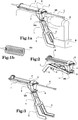
- a device comprises a body 1 for receiving a cartridge C or a deformable envelope ED containing a mastic, an adhesive or any comparable material.
- the device further comprises a transmission means 3 for receiving a rotational movement generated by an electric hand tool such as a motorized drill or screwdriver O, attached to the body 1 of the device by means of the link arm 4 and for transmitting this rotational movement by means of the transmission means 3 to the pusher P via its shaft T.
- an electric hand tool such as a motorized drill or screwdriver O
- the figure 2 represents the device of the invention in the packaging or storage.
- the transmission means 3 and its force input shaft 6 making it possible to be introduced and clamped in the mandrel ML of a motorized drill or screwdriver O, as well as the link arm 4, supporting the two halves - 5 and 5 'forks materializing a trapezoidal TZ shape, retained by an MS hinge in the folded position.
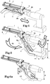
- the figure 4 schematically represents the first movement of engagement and disengagement of the device on a motorized drill or screwdriver O, more precisely of its mandrel ML, on the attachment end 6 of the gearbox 3.
- the motorized drill or screwdriver O is moved in translation along the force input axis 6 of the device in the direction of the gearbox 3.
- the operation and implementation of the device characterizing the invention is carried out according to the following;
- the main body of the device 1 figures: 1a, 4, 5, 6a, is presented in front of the motorized drill or screwdriver O, the attachment end 6 is inserted into the ML chuck of the motorized drill or screwdriver O, figure 4 .
- the user unfolds the link arm 4 supporting the two half-forks 5 and 5 'and articulated on an MS axis supporting a mechanical means for locking in position, figure 7 .
- the link arm 4 and its two half-forks 5 and 5 'then clamp thanks to their trapezoidal shape TZ, the flanks FL and FL' of the battery (body) B positioned under the handle PO of the motorized drill or screwdriver O and / or the PT work handle and adjust to it more effectively, figures 5 and 6a .
- the user positions a cartridge C or deformable envelope ED, figure 1a, of glue or the like, in the recess provided for this purpose in the main body 1.
- This procedure is conventional for many other materials intended for this purpose. to the same task.
- the link arm 4 in its telescopic version, consists of a body 4 'and a second body 4 "sliding linearly one inside the other, allowing the precise adjustment of the length of the link arm 4 to the motorized drill or screwdriver and its battery (body) B or / and its working handle PT.
Landscapes
- Engineering & Computer Science (AREA)
- Mechanical Engineering (AREA)
- Percussive Tools And Related Accessories (AREA)
- Coating Apparatus (AREA)
- Processing Of Stones Or Stones Resemblance Materials (AREA)
Claims (7)
- Vorrichtung, umfassend:i) einen Hauptkörper (1), in der Lage, eine verformbare Hülle (ED) oder eine Patrone mit beweglichem Boden (C) aufzunehmen, die ein visköses Material, wie etwa Klebstoff oder Kitt, enthält,ii) einen Drücker (P), der erlaubt, zum Auftragen eines viskösen Materials eine axiale Kraft auf einen beweglichen Patronenboden oder auf einen hinteren Teil einer verformbaren Hülle auszuüben,iii) ein Kraftübertragungsmittel (3), das mit dem Drücker (P) verbunden ist und dafür ausgebildet ist, durch Umwandlung einer Rotationsbewegung, die durch eine motorisierte Bohr- oder Schraubmaschine (O) erzeugt wird, wenn diese über eine Krafteintrittsachse (6) der Vorrichtung an das genannte Übertragungsmittel (3) gekoppelt ist, in eine geradlinige Bewegung, den genannten Drücker (P) zu verschieben,iv) mindestens einen Verbindungsarm (4), der zwei Halbgabeln (5, 5') trägt, die die Verriegelung in und gegen Uhrzeigerrichtung des Hauptkörpers (1) mit einer motorisierten Bohr- oder Schraubmaschine (O) erlauben,v) ein mechanisches Mittel (MS) zum Blockieren des Verbindungsarmes und der beiden Halbgabeln (5, 5') in Stellung,vi) mindestens eine Gelenkachse, die das mechanische Blockiermittel (MS) in Stellung trägt,wobei der genannte Verbindungsarm (4) um die genannte mindestens eine Gelenkachse und das mechanische Stellungsblockiermittel gelenkig gelagert ist
dadurch gekennzeichnet, dass die genannte mindestens eine Gelenkachse horizontal ist und rechtwinklig zur Achse (6). - Vorrichtung nach Patentanspruch 1, dadurch gekennzeichnet, dass die beiden Halbgabeln (5, 5') des Verbindungsarmes (4) Anlagepunkte aufweisen, die in der Lage sind, den Hauptkörper (1) gegen Rotation in oder gegen Uhrzeigerrichtung relativ zu einer motorisierten Bohr- oder Schraubmaschine (O) zu arretieren.
- Vorrichtung nach den Patentansprüchen 1 oder 2, dadurch gekennzeichnet, dass die genannten zwei Halbgabeln (5 und 5') ein Trapez (TZ) bilden, das die Verriegelung des Verbindungsarmes (4) mit jeder Art von motorisierter Bohr- oder Schraubmaschine (O) erleichtert.
- Vorrichtung nach Patentanspruch 3, dadurch gekennzeichnet, dass die Gelenkverbindung um die Gelenkachse geeignet ist, die Entfaltung und Justierung des Verbindungsarmes (4) in einem Winkel (α) zu erlauben, der in einer vertikalen Ebene gemessen wird, in der die Achse (6) verläuft.
- Vorrichtung nach Patentanspruch 4, dadurch gekennzeichnet, dass der Verbindungsarm (4) unter den Körper (1) einfaltbar ist und durch das Blockiermittel (MS) in Stellung gehalten wird, um sie leichter verpacken und wegräumen zu können.
- Vorrichtung nach irgendeinem der vorangehenden Patentansprüche, dadurch gekennzeichnet, dass der Verbindungsarm (4) und gegebenenfalls seine beiden Halbgabeln (5 und 5') aus geformtem Kunststoff bestehen und geeignet sind, im Betrieb der Vorrichtung als Stoß- und Drehmomentdämpferteil zu arbeiten.
- Vorrichtung nach irgendeinem der vorangehenden Patentansprüche, dadurch gekennzeichnet, dass der Verbindungsarm (4) einen ersten Körper (4') relativ zu einem zweiten Körper (4") linear gleitend umfasst, derart, dass ein einschiebbarer Verbindungsarm (4) gebildet wird.
Applications Claiming Priority (1)
| Application Number | Priority Date | Filing Date | Title |
|---|---|---|---|
| FR1402043A FR3025730B1 (fr) | 2014-09-15 | 2014-09-15 | Nouveau dispositif de solidarisation d'un applicateur de colle, ou autre produit, sur une perceuse ou visseuse |
Publications (2)
| Publication Number | Publication Date |
|---|---|
| EP2995386A1 EP2995386A1 (de) | 2016-03-16 |
| EP2995386B1 true EP2995386B1 (de) | 2020-08-05 |
Family
ID=52589418
Family Applications (1)
| Application Number | Title | Priority Date | Filing Date |
|---|---|---|---|
| EP15002671.4A Active EP2995386B1 (de) | 2014-09-15 | 2015-09-15 | Vorrichtung zur festen verbindung eines kleber-applikators auf einer motorbetriebenen bohr- oder schraubmaschine |
Country Status (2)
| Country | Link |
|---|---|
| EP (1) | EP2995386B1 (de) |
| FR (1) | FR3025730B1 (de) |
Cited By (2)
| Publication number | Priority date | Publication date | Assignee | Title |
|---|---|---|---|---|
| US20220331942A1 (en) * | 2021-04-16 | 2022-10-20 | Black & Decker Inc. | Power tool accessory system with brace |
| US20240066676A1 (en) * | 2021-04-16 | 2024-02-29 | Black & Decker Inc. | Power tool accessory system with brace |
Families Citing this family (4)
| Publication number | Priority date | Publication date | Assignee | Title |
|---|---|---|---|---|
| DE102020205316A1 (de) | 2020-04-27 | 2021-10-28 | Festool Gmbh | Vorsatzgerät und Verfahren |
| USD951741S1 (en) | 2020-10-14 | 2022-05-17 | Simpson Strong-Tie Company Inc. | Screw driving tool |
| USD951050S1 (en) | 2020-10-14 | 2022-05-10 | Simpson Strong-Tie Company Inc. | Fastener driving tool adapter |
| CN114043524B (zh) * | 2021-12-10 | 2023-12-26 | 上海锐数微医疗科技发展有限公司 | 一种可折叠且能够锁止的机械臂 |
Family Cites Families (7)
| Publication number | Priority date | Publication date | Assignee | Title |
|---|---|---|---|---|
| US3913799A (en) * | 1974-02-28 | 1975-10-21 | Davis George B Jun | Caulking gun adapter for electric hand drill |
| US5058781A (en) * | 1990-10-29 | 1991-10-22 | Aronie Alan B | Caulking gun with drive means which facilitate the immediate release of pressure from the piston |
| FR2732625A1 (fr) * | 1995-04-10 | 1996-10-11 | Fechino Mireille Latapy | Distributeur de produit visqueux, pateux ou liquide |
| DE29510534U1 (de) * | 1995-06-29 | 1996-10-31 | Fischerwerke Artur Fischer Gmbh & Co Kg, 72178 Waldachtal | Auspreßvorrichtung für Kartuschen |
| US6041976A (en) * | 1998-05-14 | 2000-03-28 | Robertson; Roger C. | Adhesive dispensing tool for use with a rotary power tool |
| FR2929537B1 (fr) * | 2008-04-07 | 2011-03-18 | Fabien Viennois | Pistolet pour appliquer une matiere contenue dans une cartouche. |
| WO2010122558A1 (en) * | 2009-04-22 | 2010-10-28 | Wadeeh Zahr | Material dispensing system |
-
2014
- 2014-09-15 FR FR1402043A patent/FR3025730B1/fr not_active Expired - Fee Related
-
2015
- 2015-09-15 EP EP15002671.4A patent/EP2995386B1/de active Active
Non-Patent Citations (1)
| Title |
|---|
| None * |
Cited By (2)
| Publication number | Priority date | Publication date | Assignee | Title |
|---|---|---|---|---|
| US20220331942A1 (en) * | 2021-04-16 | 2022-10-20 | Black & Decker Inc. | Power tool accessory system with brace |
| US20240066676A1 (en) * | 2021-04-16 | 2024-02-29 | Black & Decker Inc. | Power tool accessory system with brace |
Also Published As
| Publication number | Publication date |
|---|---|
| FR3025730B1 (fr) | 2018-03-09 |
| EP2995386A1 (de) | 2016-03-16 |
| FR3025730A1 (fr) | 2016-03-18 |
Similar Documents
| Publication | Publication Date | Title |
|---|---|---|
| EP2995386B1 (de) | Vorrichtung zur festen verbindung eines kleber-applikators auf einer motorbetriebenen bohr- oder schraubmaschine | |
| EP1961531B1 (de) | Befestigungsvorrichtung mit versenkbarem Handhebel und Geräte eine solche Vorrichtung enthaltend | |
| EP2389264B1 (de) | Werkzeugspannfutter zum vorsehen an einer rotierenden maschine | |
| EP0623429A1 (de) | Pneumatisches Werkzeug | |
| FR3000418A3 (fr) | Mecanisme de fixation d'accessoires et outil electrique equipe | |
| CH707490A1 (fr) | Clé dynamométrique. | |
| EP1702694B1 (de) | Werkzeugspannfutter für drehende Maschine, mit Verriegelungsmittel | |
| CA2591973A1 (fr) | Cle a cliquet | |
| FR2678538A1 (fr) | Outil de vissage. | |
| EP1883486B1 (de) | Werkzeughalterfutter für eine Rotationsmaschine, im Besonderen für einen Schlagschrauber | |
| EP1649980B1 (de) | Werkzeug mit Drehmomentbegrenzung | |
| EP1345001B1 (de) | Karabine mit lösbarer Laufbefestigung | |
| EP3416880A1 (de) | Aufhängungskit mit anpassbarer kompression für ein fahrzeug | |
| FR2929537A1 (fr) | Pistolet pour appliquer une matiere contenue dans une cartouche. | |
| FR2766117A1 (fr) | Outil pour vissages multiples | |
| EP3829014B1 (de) | Gerät mit einer kippbaren gerätehalterung und einem verriegelungssystem, das mittels eines kippbaren betätigungsknopfes entriegelt werden kann | |
| EP0468859B1 (de) | Schraubwerkzeug mit voreinstellbarem Anzugsmoment | |
| EP1992535B1 (de) | Steuervorrichtung für Parkbremse eines Kraftfahrzeugs | |
| FR3022816A1 (fr) | Outil pour la mise en place d'une fixation a serrer dans une zone difficile d'acces | |
| FR2924969A1 (fr) | Pince pour pose de cheville d'ancrage a douille retractable et compressible | |
| EP1764467A2 (de) | Kastenausgang, insbesondere zur Unterstützung einer Antriebskurbel eines Rollladens und einer mit einem derartigen Kastenausgang versehenen Antriebsvorrichtung | |
| FR2907868A1 (fr) | Embrayage a friction, a forte capacite de couple transmissible, notamment pour vehicule automobile | |
| FR2746743A1 (fr) | Bras d'essuie-glace, notamment pour vehicule automobile | |
| FR3052089A1 (fr) | Mandrin porte-foret | |
| EP1504848A1 (de) | Schraubstockzange |
Legal Events
| Date | Code | Title | Description |
|---|---|---|---|
| PUAI | Public reference made under article 153(3) epc to a published international application that has entered the european phase |
Free format text: ORIGINAL CODE: 0009012 |
|
| AK | Designated contracting states |
Kind code of ref document: A1 Designated state(s): AL AT BE BG CH CY CZ DE DK EE ES FI FR GB GR HR HU IE IS IT LI LT LU LV MC MK MT NL NO PL PT RO RS SE SI SK SM TR |
|
| AX | Request for extension of the european patent |
Extension state: BA ME |
|
| 17P | Request for examination filed |
Effective date: 20160719 |
|
| RBV | Designated contracting states (corrected) |
Designated state(s): AL AT BE BG CH CY CZ DE DK EE ES FI FR GB GR HR HU IE IS IT LI LT LU LV MC MK MT NL NO PL PT RO RS SE SI SK SM TR |
|
| STAA | Information on the status of an ep patent application or granted ep patent |
Free format text: STATUS: EXAMINATION IS IN PROGRESS |
|
| 17Q | First examination report despatched |
Effective date: 20190322 |
|
| RAP1 | Party data changed (applicant data changed or rights of an application transferred) |
Owner name: ALPHA INDUSTRIE PLASTIQUE |
|
| RIN1 | Information on inventor provided before grant (corrected) |
Inventor name: VIENNOIS, FABIEN |
|
| GRAP | Despatch of communication of intention to grant a patent |
Free format text: ORIGINAL CODE: EPIDOSNIGR1 |
|
| STAA | Information on the status of an ep patent application or granted ep patent |
Free format text: STATUS: GRANT OF PATENT IS INTENDED |
|
| RIC1 | Information provided on ipc code assigned before grant |
Ipc: B05C 17/01 20060101AFI20200127BHEP Ipc: B25F 3/00 20060101ALI20200127BHEP |
|
| INTG | Intention to grant announced |
Effective date: 20200227 |
|
| GRAS | Grant fee paid |
Free format text: ORIGINAL CODE: EPIDOSNIGR3 |
|
| GRAA | (expected) grant |
Free format text: ORIGINAL CODE: 0009210 |
|
| STAA | Information on the status of an ep patent application or granted ep patent |
Free format text: STATUS: THE PATENT HAS BEEN GRANTED |
|
| AK | Designated contracting states |
Kind code of ref document: B1 Designated state(s): AL AT BE BG CH CY CZ DE DK EE ES FI FR GB GR HR HU IE IS IT LI LT LU LV MC MK MT NL NO PL PT RO RS SE SI SK SM TR |
|
| REG | Reference to a national code |
Ref country code: GB Ref legal event code: FG4D Free format text: NOT ENGLISH |
|
| REG | Reference to a national code |
Ref country code: CH Ref legal event code: EP |
|
| REG | Reference to a national code |
Ref country code: AT Ref legal event code: REF Ref document number: 1297976 Country of ref document: AT Kind code of ref document: T Effective date: 20200815 |
|
| REG | Reference to a national code |
Ref country code: DE Ref legal event code: R096 Ref document number: 602015056769 Country of ref document: DE |
|
| REG | Reference to a national code |
Ref country code: IE Ref legal event code: FG4D Free format text: LANGUAGE OF EP DOCUMENT: FRENCH |
|
| REG | Reference to a national code |
Ref country code: CH Ref legal event code: NV Representative=s name: VALIPAT S.A. C/O BOVARD SA NEUCHATEL, CH |
|
| REG | Reference to a national code |
Ref country code: LT Ref legal event code: MG4D |
|
| REG | Reference to a national code |
Ref country code: NL Ref legal event code: MP Effective date: 20200805 |
|
| REG | Reference to a national code |
Ref country code: AT Ref legal event code: MK05 Ref document number: 1297976 Country of ref document: AT Kind code of ref document: T Effective date: 20200805 |
|
| PG25 | Lapsed in a contracting state [announced via postgrant information from national office to epo] |
Ref country code: PT Free format text: LAPSE BECAUSE OF FAILURE TO SUBMIT A TRANSLATION OF THE DESCRIPTION OR TO PAY THE FEE WITHIN THE PRESCRIBED TIME-LIMIT Effective date: 20201207 Ref country code: BG Free format text: LAPSE BECAUSE OF FAILURE TO SUBMIT A TRANSLATION OF THE DESCRIPTION OR TO PAY THE FEE WITHIN THE PRESCRIBED TIME-LIMIT Effective date: 20201105 Ref country code: ES Free format text: LAPSE BECAUSE OF FAILURE TO SUBMIT A TRANSLATION OF THE DESCRIPTION OR TO PAY THE FEE WITHIN THE PRESCRIBED TIME-LIMIT Effective date: 20200805 Ref country code: LT Free format text: LAPSE BECAUSE OF FAILURE TO SUBMIT A TRANSLATION OF THE DESCRIPTION OR TO PAY THE FEE WITHIN THE PRESCRIBED TIME-LIMIT Effective date: 20200805 Ref country code: HR Free format text: LAPSE BECAUSE OF FAILURE TO SUBMIT A TRANSLATION OF THE DESCRIPTION OR TO PAY THE FEE WITHIN THE PRESCRIBED TIME-LIMIT Effective date: 20200805 Ref country code: AT Free format text: LAPSE BECAUSE OF FAILURE TO SUBMIT A TRANSLATION OF THE DESCRIPTION OR TO PAY THE FEE WITHIN THE PRESCRIBED TIME-LIMIT Effective date: 20200805 Ref country code: SE Free format text: LAPSE BECAUSE OF FAILURE TO SUBMIT A TRANSLATION OF THE DESCRIPTION OR TO PAY THE FEE WITHIN THE PRESCRIBED TIME-LIMIT Effective date: 20200805 Ref country code: NO Free format text: LAPSE BECAUSE OF FAILURE TO SUBMIT A TRANSLATION OF THE DESCRIPTION OR TO PAY THE FEE WITHIN THE PRESCRIBED TIME-LIMIT Effective date: 20201105 Ref country code: FI Free format text: LAPSE BECAUSE OF FAILURE TO SUBMIT A TRANSLATION OF THE DESCRIPTION OR TO PAY THE FEE WITHIN THE PRESCRIBED TIME-LIMIT Effective date: 20200805 Ref country code: GR Free format text: LAPSE BECAUSE OF FAILURE TO SUBMIT A TRANSLATION OF THE DESCRIPTION OR TO PAY THE FEE WITHIN THE PRESCRIBED TIME-LIMIT Effective date: 20201106 |
|
| PG25 | Lapsed in a contracting state [announced via postgrant information from national office to epo] |
Ref country code: RS Free format text: LAPSE BECAUSE OF FAILURE TO SUBMIT A TRANSLATION OF THE DESCRIPTION OR TO PAY THE FEE WITHIN THE PRESCRIBED TIME-LIMIT Effective date: 20200805 Ref country code: NL Free format text: LAPSE BECAUSE OF FAILURE TO SUBMIT A TRANSLATION OF THE DESCRIPTION OR TO PAY THE FEE WITHIN THE PRESCRIBED TIME-LIMIT Effective date: 20200805 Ref country code: LV Free format text: LAPSE BECAUSE OF FAILURE TO SUBMIT A TRANSLATION OF THE DESCRIPTION OR TO PAY THE FEE WITHIN THE PRESCRIBED TIME-LIMIT Effective date: 20200805 Ref country code: PL Free format text: LAPSE BECAUSE OF FAILURE TO SUBMIT A TRANSLATION OF THE DESCRIPTION OR TO PAY THE FEE WITHIN THE PRESCRIBED TIME-LIMIT Effective date: 20200805 Ref country code: IS Free format text: LAPSE BECAUSE OF FAILURE TO SUBMIT A TRANSLATION OF THE DESCRIPTION OR TO PAY THE FEE WITHIN THE PRESCRIBED TIME-LIMIT Effective date: 20201205 |
|
| PG25 | Lapsed in a contracting state [announced via postgrant information from national office to epo] |
Ref country code: EE Free format text: LAPSE BECAUSE OF FAILURE TO SUBMIT A TRANSLATION OF THE DESCRIPTION OR TO PAY THE FEE WITHIN THE PRESCRIBED TIME-LIMIT Effective date: 20200805 Ref country code: SM Free format text: LAPSE BECAUSE OF FAILURE TO SUBMIT A TRANSLATION OF THE DESCRIPTION OR TO PAY THE FEE WITHIN THE PRESCRIBED TIME-LIMIT Effective date: 20200805 Ref country code: RO Free format text: LAPSE BECAUSE OF FAILURE TO SUBMIT A TRANSLATION OF THE DESCRIPTION OR TO PAY THE FEE WITHIN THE PRESCRIBED TIME-LIMIT Effective date: 20200805 Ref country code: DK Free format text: LAPSE BECAUSE OF FAILURE TO SUBMIT A TRANSLATION OF THE DESCRIPTION OR TO PAY THE FEE WITHIN THE PRESCRIBED TIME-LIMIT Effective date: 20200805 Ref country code: CZ Free format text: LAPSE BECAUSE OF FAILURE TO SUBMIT A TRANSLATION OF THE DESCRIPTION OR TO PAY THE FEE WITHIN THE PRESCRIBED TIME-LIMIT Effective date: 20200805 |
|
| REG | Reference to a national code |
Ref country code: DE Ref legal event code: R097 Ref document number: 602015056769 Country of ref document: DE |
|
| PG25 | Lapsed in a contracting state [announced via postgrant information from national office to epo] |
Ref country code: AL Free format text: LAPSE BECAUSE OF FAILURE TO SUBMIT A TRANSLATION OF THE DESCRIPTION OR TO PAY THE FEE WITHIN THE PRESCRIBED TIME-LIMIT Effective date: 20200805 Ref country code: MC Free format text: LAPSE BECAUSE OF FAILURE TO SUBMIT A TRANSLATION OF THE DESCRIPTION OR TO PAY THE FEE WITHIN THE PRESCRIBED TIME-LIMIT Effective date: 20200805 |
|
| PLBE | No opposition filed within time limit |
Free format text: ORIGINAL CODE: 0009261 |
|
| STAA | Information on the status of an ep patent application or granted ep patent |
Free format text: STATUS: NO OPPOSITION FILED WITHIN TIME LIMIT |
|
| PG25 | Lapsed in a contracting state [announced via postgrant information from national office to epo] |
Ref country code: LU Free format text: LAPSE BECAUSE OF NON-PAYMENT OF DUE FEES Effective date: 20200915 Ref country code: SK Free format text: LAPSE BECAUSE OF FAILURE TO SUBMIT A TRANSLATION OF THE DESCRIPTION OR TO PAY THE FEE WITHIN THE PRESCRIBED TIME-LIMIT Effective date: 20200805 |
|
| 26N | No opposition filed |
Effective date: 20210507 |
|
| PG25 | Lapsed in a contracting state [announced via postgrant information from national office to epo] |
Ref country code: IT Free format text: LAPSE BECAUSE OF FAILURE TO SUBMIT A TRANSLATION OF THE DESCRIPTION OR TO PAY THE FEE WITHIN THE PRESCRIBED TIME-LIMIT Effective date: 20200805 |
|
| PG25 | Lapsed in a contracting state [announced via postgrant information from national office to epo] |
Ref country code: SI Free format text: LAPSE BECAUSE OF FAILURE TO SUBMIT A TRANSLATION OF THE DESCRIPTION OR TO PAY THE FEE WITHIN THE PRESCRIBED TIME-LIMIT Effective date: 20200805 Ref country code: IE Free format text: LAPSE BECAUSE OF NON-PAYMENT OF DUE FEES Effective date: 20200915 |
|
| PG25 | Lapsed in a contracting state [announced via postgrant information from national office to epo] |
Ref country code: TR Free format text: LAPSE BECAUSE OF FAILURE TO SUBMIT A TRANSLATION OF THE DESCRIPTION OR TO PAY THE FEE WITHIN THE PRESCRIBED TIME-LIMIT Effective date: 20200805 Ref country code: MT Free format text: LAPSE BECAUSE OF FAILURE TO SUBMIT A TRANSLATION OF THE DESCRIPTION OR TO PAY THE FEE WITHIN THE PRESCRIBED TIME-LIMIT Effective date: 20200805 Ref country code: CY Free format text: LAPSE BECAUSE OF FAILURE TO SUBMIT A TRANSLATION OF THE DESCRIPTION OR TO PAY THE FEE WITHIN THE PRESCRIBED TIME-LIMIT Effective date: 20200805 |
|
| PG25 | Lapsed in a contracting state [announced via postgrant information from national office to epo] |
Ref country code: MK Free format text: LAPSE BECAUSE OF FAILURE TO SUBMIT A TRANSLATION OF THE DESCRIPTION OR TO PAY THE FEE WITHIN THE PRESCRIBED TIME-LIMIT Effective date: 20200805 |
|
| PGFP | Annual fee paid to national office [announced via postgrant information from national office to epo] |
Ref country code: DE Payment date: 20240925 Year of fee payment: 10 |
|
| PGFP | Annual fee paid to national office [announced via postgrant information from national office to epo] |
Ref country code: GB Payment date: 20240919 Year of fee payment: 10 |
|
| PGFP | Annual fee paid to national office [announced via postgrant information from national office to epo] |
Ref country code: BE Payment date: 20240926 Year of fee payment: 10 |
|
| PGFP | Annual fee paid to national office [announced via postgrant information from national office to epo] |
Ref country code: CH Payment date: 20241001 Year of fee payment: 10 |
|
| PGFP | Annual fee paid to national office [announced via postgrant information from national office to epo] |
Ref country code: FR Payment date: 20250919 Year of fee payment: 11 |