EP2586928A2 - Support de plaque en particulier pour panneaux en verre - Google Patents
Support de plaque en particulier pour panneaux en verre Download PDFInfo
- Publication number
- EP2586928A2 EP2586928A2 EP12007302.8A EP12007302A EP2586928A2 EP 2586928 A2 EP2586928 A2 EP 2586928A2 EP 12007302 A EP12007302 A EP 12007302A EP 2586928 A2 EP2586928 A2 EP 2586928A2
- Authority
- EP
- European Patent Office
- Prior art keywords
- latching
- plate holder
- plate
- holder according
- angle
- Prior art date
- Legal status (The legal status is an assumption and is not a legal conclusion. Google has not performed a legal analysis and makes no representation as to the accuracy of the status listed.)
- Granted
Links
Images


Classifications
-
- E—FIXED CONSTRUCTIONS
- E04—BUILDING
- E04F—FINISHING WORK ON BUILDINGS, e.g. STAIRS, FLOORS
- E04F13/00—Coverings or linings, e.g. for walls or ceilings
- E04F13/07—Coverings or linings, e.g. for walls or ceilings composed of covering or lining elements; Sub-structures therefor; Fastening means therefor
- E04F13/08—Coverings or linings, e.g. for walls or ceilings composed of covering or lining elements; Sub-structures therefor; Fastening means therefor composed of a plurality of similar covering or lining elements
- E04F13/0801—Separate fastening elements
- E04F13/0832—Separate fastening elements without load-supporting elongated furring elements between wall and covering elements
- E04F13/0853—Separate fastening elements without load-supporting elongated furring elements between wall and covering elements adjustable perpendicular to the wall
-
- E—FIXED CONSTRUCTIONS
- E04—BUILDING
- E04F—FINISHING WORK ON BUILDINGS, e.g. STAIRS, FLOORS
- E04F13/00—Coverings or linings, e.g. for walls or ceilings
- E04F13/07—Coverings or linings, e.g. for walls or ceilings composed of covering or lining elements; Sub-structures therefor; Fastening means therefor
- E04F13/08—Coverings or linings, e.g. for walls or ceilings composed of covering or lining elements; Sub-structures therefor; Fastening means therefor composed of a plurality of similar covering or lining elements
- E04F13/14—Coverings or linings, e.g. for walls or ceilings composed of covering or lining elements; Sub-structures therefor; Fastening means therefor composed of a plurality of similar covering or lining elements stone or stone-like materials, e.g. ceramics concrete; of glass or with an outer layer of stone or stone-like materials or glass
- E04F13/145—Coverings or linings, e.g. for walls or ceilings composed of covering or lining elements; Sub-structures therefor; Fastening means therefor composed of a plurality of similar covering or lining elements stone or stone-like materials, e.g. ceramics concrete; of glass or with an outer layer of stone or stone-like materials or glass with an outer layer of glass
Definitions
- the invention relates to a plate holder in particular for glass panels according to the preamble of claim 1.
- plate holder in the sense of the present invention is understood to mean a holder which is suitable for holding any panels or plates on a wall surface, a roof surface or the like. Such wall surfaces may be present in the interior or exterior of buildings.
- the plate holder according to the invention can also be mounted on freestanding walls, in particular sound insulation walls or privacy screens or weather protection walls for holding plates or sheets of any kind.
- the invention provides a novel plate holder, which is suitable for all plate or tabular materials, in particular glass sheets of any composition, in particular tempered glass or laminated safety glass panels, but also glass composite panels, such.
- glass sheets of any composition in particular tempered glass or laminated safety glass panels, but also glass composite panels, such.
- photovoltaic panels soundproofing panels, even if they are perforated, ribbed or otherwise have a textured surface.
- the following invention describes the use of glass panels; however, it is not limited thereto.
- plate holder for the holder of glass panels as a clamp holder. It is an angle profile, which is attached to a mounting surface and having a rear, vertical leg which forms the wall-side contact surface for the glass panel to be mounted thereon.
- the (visible) front of the glass sheet is clamped by a counter-holder or by a vertical leg of a counter-holder, which is connected via a screw connection with the rear holder. Between the two holders a receiving space is provided, in which the glass sheet to be held is inserted and held on the front side.
- a clamped holder is achieved by pressing the front counter-holder against the rear part with the pressing force of the screw connection so as to fix the glass sheet held in the receiving space under lateral pressure in the receiving space.
- the screw is also easy to install and also there is a risk that parts of the screw deflect, rot, corrode or wear out, which is undesirable.
- the invention is therefore based on the object, a plate holder, in particular for glass panels of the type mentioned in such a way that it forms a visual side as smooth as possible surface with minimal installation effort, the no protrusions such. B. screw or rivet or the like is impaired.
- the invention is characterized by the technical teaching of claim 1.
- An essential feature of the invention is that the lower panel side enclosing part of the glass holder is designed to be pluggable.
- the invention provides that the part of the glass holder which encloses the lower side of the sheet of the material panel is arranged on the visible side of the glass holder.
- the invention provides that the part of the glass holder which encloses the lower side of the sheet of the material panel is arranged on the wall side of the glass holder.
- the part of the glass holder enclosing the lower panel side of the material panel is disposed on the visible side of the material panel, although the invention is not limited thereto.
- this part is designed as a plug-in or latchable latching angle.
- This is understood to mean an L-shaped part, one leg of which, e.g. the longer L-leg, the lower side of the material plate to be held bounded on the front side and forms the front (preferably visible) portion of a receiving opening, while the other leg, e.g. the shorter part of the L-leg of this locking angle forms a latching tongue.
- the latching tongue is adapted to be snapped into a slot formed as a recess in the opposite support bracket, thereby completing the receiving opening in the plate holder.
- the latching angle in the direction perpendicular to the plane of the wall surface - ie frontally from front to be attached to the stationary support angle.
- the Einrastwinkel can also be inserted laterally (parallel to the plane of the wall surface) in a rectified insertion opening on the stationary support member and locked.
- a frontal latching as the invention prefers, in another embodiment also a lateral latching can be provided. Their plugging direction is offset by 90 degrees to the frontal latching.
- the one leg for example, the shorter L-leg, the Einrastwinkels formed as a latching tongue, which is particularly is preferred if this latching tongue is plate-shaped and has on its underside a jumping over the lower surface addition locking lug or locking rib, which preferably extends over the entire width of the latching tongue.
- the invention is not limited thereto; the locking lug or the projecting locking rib may also be present piecewise on the underside of the latching tongue.
- latching tongue is understood in particular a planar or plate-shaped part, but it may also be provided in another embodiment that the latching tongue is replaced by individual parallel juxtaposed and spaced apart mutually formed latching pins or a single latching pin.
- this latching tongue in an associated insertion opening at the stationarily arranged, wall-side support bracket can be inserted and latched, it being preferred if this latching connection issverfestigend and self-consolidating under the load of the down by weight pressing material plate.
- a stop member is arranged, which applies behind an undercut slot in the region of the stationary support leg and there in the area in the insertion opening to avoid in that the latching angle pivots out or out of the insertion opening of the support bracket.
- the stop member which comes to rest on the undercut groove in the support bracket, thus laying load-transmitting on the underside of the groove and prevents the Einrastwinkel from pivoting out of the insertion opening.
- a backup is given in two mutually perpendicular planes, namely once a backup against withdrawal in a horizontal plane is given by the latching connection and arranged at the rear end of the latching tongue stop member ensures in the vertical direction that the part is not from the latching connection pans out.
- the possibility is created for the first time to provide a lockable or plug-in plate holder, in particular a glass panel holder completely without tools and without further fastening means, in which one part is formed as Einrastwinkel and that part of itself at the front in the region of the lower edge the material plate to be held applies.
- lower edge is understood to mean that the lower region of the material plate is held by the latching angle according to the invention, which is arranged pluggable in the support angle.
- the latching connection according to the invention is particularly highly resilient, it is wear-free and the power transmission is ideal, because a tearing of the latching connection is avoided by a itself solidifying under the load of the material plate latching connection.
- the assembly is particularly simple because a simply designed Einrastwinkel is provided which is interchangeable with a simple latching connection with the fixed support bracket via a slide-in guide.
- the assembly is particularly quick and cost effective, because you can do without tools.
- the invention is not limited to that the interchangeable formed Einrastwinkel is formed of the same material as the material of the fixed support angle.
- the Einrastwinkel can also be designed from a different material, in particular a plastic material.
- latching lug which is arranged projecting over the underside of the latching tongue firmly on the underside of the latching tongue can also be designed as a replaceable or retractable latching connection.
- a slide-in profile is arranged in the latching angle, and in this slide-in profile a triangular or multi-stop surfaces provided insertion wedge or an insertion bar can be inserted, which then replaces the latching lug according to the first embodiment.
- latching lug or the mutually complementary stop surfaces extend over the entire width of the latching tongue. These can also be arranged only laterally on the latching tongue and also protrude only laterally into the insertion opening of the support bracket.
- the arranged at the stationary support angle in the region of the insertion opening stop edge is replaceable.
- an approximately rectangular profile strip can be laterally inserted into the front of the insertion opening.
- latching lug or the latching means projecting out of the surface of the latching tongue are arranged on the underside of the latching tongue in the region of the plug-in latching angle.
- the invention is not limited to fixed latching tongues or latching elements; these can also be configured as spring tongues, as bending tongues or as spring elements.
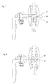
- FIGS. 1 to 5 In general, a plate holder 1 is shown, which in principle consists of the parts according to FIGS. 3 and 4 consists.
- FIG. 1 and 3 is attached to a mounting surface not shown, a base angle 2, wherein z. B. a screw is used and the fixing screws not shown in each case by adjusting disks 3 arranged through, and cover the adjusting discs 3 slots.
- the plate holder 1 of the invention is screwed to a mounting surface.
- this has a front horizontal leg 4, in which a vertical bore 5 is provided, through which a fastening screw 6 engages, which fixes the horizontal leg 7 of a stationary arranged support bracket 8.
- the arranged on the attachment side support bracket 8 is according to FIG. 3 from the rear horizontal leg 7 and a material integrally adjoining vertical part, which consists of the upper vertical leg 10 and the subsequent vertical leg 11 below.
- the two vertical legs 10, 11 are preferably material in one piece (made of the same material) connected to each other and together with all other parts of the support bracket 8 is an integral part, which can be preferably made of an aluminum extruded or aluminum die-cast profile. It can also be a zinc die-casting used or a plastic profile or a composite material. Instead of a one-piece part can therefore a composite part composed of several parts or materials may also be used.
- the parts mentioned can also consist of a stainless steel material, in particular a chrome-nickel steel.
- the fastening screw 6 is underlaid with an adjusting disk 9, as a result of which the wall-side screw connection is provided.
- this screw can be made of one or more screws 6 replaced by other fasteners, such.
- clamped connections plug-in connections, welded joints, riveted joints and adhesive joints and the like.
- the wall-side formation of the stationary support bracket 8 consists of two oppositely directed vertical legs 10, 11, which form the wall-side contact surface for a receiving opening 38, in which the material plate 29, 30 is inserted and held.
- FIG. 3 forms the support bracket 8 at its front side a horizontal support leg 12, in which approximately centrally an insertion opening 14 is provided for the latching receiving a Einrastwinkels 20.
- the support leg 12 is - as I said - formed horizontally and material ein Communityig about at an angle of 90 ° in a subsequent downwardly directed vertical leg 13, which forms a lower receiving opening for receiving the upper side of any material plate 29, 30.
- the specified angle of 90 ° can be kept within limits of 70 to 100 degrees.
- the latching angle 20 consists of an upward vertical leg 21, which is connected approximately at an angle of 90 ° with an adjoining latching tongue 24 which is formed as a plate.
- the entire part is preferably made of a metal or a plastic material or a Kunststoffmetallverbund.
- the inside of the vertical leg 21 forms a bearing surface 22 for the formation of the receiving opening 38 and that further on the lower bottom surface of the latching tongue 24 a preferably extending over the entire width of the latching tongue 24 latching lug 25 is disposed over the surface of the Underside of the latching tongue 24 protrudes.
- the front free part of the latching tongue 24 is formed by a stop member 26 which is flattened and which according to FIG. 1 an upwardly directed pressure surface 27, with which the latching tongue 24 engages in an inserted slot 18 in the assembled state, so that the pressure surface 27 comes to rest on the upper side of the stop member 26 to the upper side of the undercut slot 18 and the entire Einrastwinkel 20 against an undesirable pivoting in the direction of arrow 41 protects.
- the insertion direction for the latching tongue 24 in the insertion opening 14 takes place in the direction of arrow 15th
- the locking lug 25 engages behind a stationary stop edge 16, which is arranged in the region of an end face 17 formed stop face, wherein the insertion opening 14 itself is formed as an opening, d. H. it contains no material. Therefore, the underside of the vertical leg 21, which is designed as a support surface 23, on the support surface 19 support leg 12, while the underside of the latching tongue 24 is supported by the stop surface 17 and under attack.
- the opening 14 is bridged by the latching tongue 24, wherein only the rear part of the latching tongue 24 engages with the stopper part 26 in the undercut slot 18, as shown in FIG. 1 is shown.
- FIG. 2 shows the advantages of the invention of a visual side, almost joint-free connection. It can be seen that the lower stationary vertical leg 13, which is arranged on the stationary support bracket 8, forms a continuous planar part with the vertical leg 21 of the Einrastwinkels 20 and thereby a particularly aesthetically pleasing, almost uninterrupted surface is created in which no dirt penetrate can, because the superimposed parts virtually seamlessly merge into one another and the penetration of dirt and foreign bodies is prevented.
- the holding profile 31 preferably consists of a U-profile with barb-shaped holding ribs 32, which are directed obliquely downwards against the bottom of the receiving opening 38.
- the material of the holding profile 31 can be changed within wide limits. It preferably consists of a rubber profile, or a plastic elastomer profile z. As a PU foam, made of an EPDM plastic material or any other materials that can exert a certain elastic bias on the material to be held plate 29, 30.
- the retaining ribs 32 are directed obliquely downwards against the bottom of the receiving opening 38, there is the further advantage that different plate thicknesses can be accommodated in the receiving opening 38 and that an additional bias is exerted on the side of the material plate 29, and this before the lateral tilting out of the receiving opening 38 protects.
- the directed against the bottom of the receiving opening 38 holding ribs facilitate the insertion of the respective to be held material plate 29, 30, because the Rippen give this insertion pressure and elastically deform and create a sealing on the respective side of the material plate 29, 30.
- FIG. 1 two different material plates, wherein the upper material plate 29 as a glass plate z. B. consists of an ESG material, while the lower material plate 30 as a glass plate made of a laminated safety glass material.
- each material-identical material plates 29 or 30 are installed, so that the embodiment according to FIG. 1 only the possibility of using different material plates, especially glass plates shows.
- the glass plates which are referred to herein as ESG or VSG, are also combined with different wood, metal, plastic wood composite panels and the like.
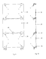
- FIG. 6 it is according to FIG. 6 provided that the previously formed as stationary and fixed to the underside of the locking lug 25 locking tongue 24 is now formed interchangeable in the form of a in FIG. 6 shown locking bar 33, perpendicular to the plane of the paper FIG. 6 For example, in the direction of arrow 34 is pulled out or hineinschiebbar, with an associated, the locking bar 33 adapted groove is present.
- the locking strip is triangular or rectangular in shape and has a plurality of stop surfaces, wherein the striking of the stationary stop edge 37 is essential.
- the stop edge 37 may also be formed replaceable.
- FIG. 7 shows the FIG. 7 also an interchangeable locking arrangement, wherein instead of one in the plane of the paper FIG. 6 retractable or retractable locking bar 33 now only one time insertable locking rod 35 is provided which is inserted once in the same manner as the locking strip 33 and which is then rotatable in the direction of arrow 36 to the eccentrically arranged on its outer circumference locking lug in engagement with the stationary stop edge 37 according to FIG. 6 bring to.
- FIG. 8 shows as a further embodiment that the locking lug 25 may be formed not only as a chamfered projection, but the locking lug may also have any other arbitrary profile, in particular a rectangle or square profile, as in the form of locking lug 45 in FIG. 8 is shown.
- the invention is not directed to the intervention of a protruding from the bottom side of the latching tongue 24 locking lug 25, 45, but in the kinematic reversal, it may also be provided that the latching lug 25, 45 is disposed in the region of the stationary part and opposite to the Bottom of the latching tongue 24 an associated latching groove is provided.
- the latching lug 25, 45 is disposed in the region of the stationary part and opposite to the Bottom of the latching tongue 24 an associated latching groove is provided.
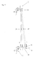
- FIGS. 9 to 11 show the assembly of any material plates on a mounting surface
- FIG. 9 shows the small-sized horizontal joint 40, which forms between the lower end face of a material plate and the upper end face of the other material plate. Namely, it requires no screw that would have to be arranged in this area and the width of the horizontal joint 40 is limited only by the material thickness of the latching tongue 24 and the associated insertion opening in the associated stationary support bracket.
- FIG. 11 shows an example mounting a material plate 29.
- the upper end face of the material plate 29 ' is inserted into the below receiving opening 39 of an upper plate holder 1.
- the material plate 29 ' is pivoted in the direction of arrow 15 at remote latching angle 20 and attached holding profile 31 with its underside.
- the lower end face of the material plate 29 is pivoted freely into the half-side opened receiving opening 39.
- the entire holding profile 31 is now under the weight load of the material plate 29 with full weight on the top of the latching tongue 24, but is also supported by the lateral regions of the support leg 12.
- the retaining profile 31 is elastically resilient, the pivoting is facilitated because the retaining profile 31 slightly compresses under the insertion movement and then expands again. In this case, a lifting of the plate is not required.
- the retaining profile can also be completely eliminated or replaced by a rigid design.
- the holding profile 31 can then be omitted if a very light plate is used, which can be easily raised or if only small plates are used, so that a lifting of the material plate to be inserted is easily possible.
Landscapes
- Engineering & Computer Science (AREA)
- Architecture (AREA)
- Civil Engineering (AREA)
- Structural Engineering (AREA)
- Chemical & Material Sciences (AREA)
- Ceramic Engineering (AREA)
- Finishing Walls (AREA)
- Connection Of Plates (AREA)
- Load-Bearing And Curtain Walls (AREA)
Priority Applications (1)
| Application Number | Priority Date | Filing Date | Title |
|---|---|---|---|
| SI201231350T SI2586928T1 (sl) | 2011-10-31 | 2012-10-24 | Držalo plošč, še zlasti za steklene plošče |
Applications Claiming Priority (1)
| Application Number | Priority Date | Filing Date | Title |
|---|---|---|---|
| DE102011117281A DE102011117281A1 (de) | 2011-10-31 | 2011-10-31 | Plattenhalter insbesondere für Glastafeln |
Publications (3)
| Publication Number | Publication Date |
|---|---|
| EP2586928A2 true EP2586928A2 (fr) | 2013-05-01 |
| EP2586928A3 EP2586928A3 (fr) | 2016-01-20 |
| EP2586928B1 EP2586928B1 (fr) | 2018-05-02 |
Family
ID=47137445
Family Applications (1)
| Application Number | Title | Priority Date | Filing Date |
|---|---|---|---|
| EP12007302.8A Active EP2586928B1 (fr) | 2011-10-31 | 2012-10-24 | Support de plaque en particulier pour panneaux en verre |
Country Status (3)
| Country | Link |
|---|---|
| EP (1) | EP2586928B1 (fr) |
| DE (1) | DE102011117281A1 (fr) |
| SI (1) | SI2586928T1 (fr) |
Families Citing this family (1)
| Publication number | Priority date | Publication date | Assignee | Title |
|---|---|---|---|---|
| DE202013009399U1 (de) * | 2013-10-23 | 2014-10-29 | Schrag Kantprofile Gmbh | Halteeinrichtung für Paneele zur Fassadenverkleidung |
Family Cites Families (6)
| Publication number | Priority date | Publication date | Assignee | Title |
|---|---|---|---|---|
| DE1165229B (de) * | 1961-04-14 | 1964-03-12 | Eltreva Ag | Mehrteiliger Profilstab fuer einen Zwischenwandrahmen od. dgl. zur loesbaren Halterung von Fuellungstafeln |
| FR2614340B1 (fr) * | 1987-04-23 | 1989-07-28 | Smac Acieroid | Dispositif de fixation des plaques d'un revetement de facade |
| JP4247070B2 (ja) * | 2003-08-12 | 2009-04-02 | フクビ化学工業株式会社 | 建築用パネル材の固定部材および建築用パネル材の固定方法 |
| DE102008000293A1 (de) * | 2008-02-13 | 2009-08-20 | Hilti Aktiengesellschaft | Befestigungsvorrichtung für die Befestigung von plattenförmigen Elementen |
| DE102009040319A1 (de) * | 2009-09-05 | 2011-03-10 | LängleGlas GmbH | Schuppenhalter für die Schnellmontage von Platten und Glastafeln sowie Verfahren zur Montage eines Schuppenhalters |
| DE202010000208U1 (de) * | 2010-02-16 | 2010-06-02 | Gust.Alberts Gmbh & Co.Kg | Montagesysteme für Platten und Rohre |
-
2011
- 2011-10-31 DE DE102011117281A patent/DE102011117281A1/de not_active Withdrawn
-
2012
- 2012-10-24 EP EP12007302.8A patent/EP2586928B1/fr active Active
- 2012-10-24 SI SI201231350T patent/SI2586928T1/sl unknown
Non-Patent Citations (1)
| Title |
|---|
| None |
Also Published As
| Publication number | Publication date |
|---|---|
| EP2586928B1 (fr) | 2018-05-02 |
| EP2586928A3 (fr) | 2016-01-20 |
| SI2586928T1 (sl) | 2018-09-28 |
| DE102011117281A1 (de) | 2013-05-02 |
Similar Documents
| Publication | Publication Date | Title |
|---|---|---|
| EP1878847B1 (fr) | Structure de mur rideau | |
| DE20015537U1 (de) | Dach- und Deckensystem | |
| EP2460949A1 (fr) | Garde-corps en panneau | |
| DE102015108275A1 (de) | Eckblende für Hohlprofil-Eckverbinder, Eckverbinder, Eckverbinder-Bausatz, Rahmenstruktur und Schutzgitter | |
| DE2059829A1 (de) | Struktursystem fuer den Zusammenbau von vorgefertigten Konstruktionen | |
| DE102007008829B4 (de) | Befestigungs-Anordnung | |
| DE202012104033U1 (de) | Haltevorrichtung für eine Brüstungs- oder Geländerplatte sowie Geländer oder Brüstung mit Scheibe | |
| DE202017104559U1 (de) | Mechanisch gesichertes Frontprofil für einen französischen Balkon | |
| DE202016101593U1 (de) | Vorrichtung gegen das Eindringen von Flüssigkeiten | |
| EP1710388B1 (fr) | Caisson de volet roulant posé sur un cadre | |
| EP3121360B1 (fr) | Système de fixation pour éléments de recouvrement | |
| EP1710363B1 (fr) | Système de mur avec panneaux de verre | |
| EP2586928B1 (fr) | Support de plaque en particulier pour panneaux en verre | |
| EP2806094B1 (fr) | Vantail pour un agencement de porte | |
| DE102016125819B4 (de) | Hinterfütterungsvorrichtung sowie damit versehene Umfassungszarge | |
| EP1647649A2 (fr) | Système de fixation de façades | |
| EP2447441B1 (fr) | Dispositif de fixation pour des éléments de bardage | |
| EP1990477B1 (fr) | Panneau de construction léger doté d'une baguette de profilé | |
| AT12441U1 (de) | Isolierverglasung für glasfassaden | |
| EP1816280A2 (fr) | Ensemble de lamelles pour façades | |
| AT519868B1 (de) | Konsolenanordnung für eine Fassadentragkonstruktion | |
| DE102010015281B4 (de) | Verfahren zum Verlegen eines Fußbodensystems | |
| AT505569A2 (de) | Türstock mit einem türblatt | |
| EP4431837A1 (fr) | Ensemble de serrage et ensemble de montage pour module de cellule solaire | |
| DE202024105271U1 (de) | Ausgleichsbauteil für mit Abstand montiertes Gebäudeteil |
Legal Events
| Date | Code | Title | Description |
|---|---|---|---|
| PUAI | Public reference made under article 153(3) epc to a published international application that has entered the european phase |
Free format text: ORIGINAL CODE: 0009012 |
|
| AK | Designated contracting states |
Kind code of ref document: A2 Designated state(s): AL AT BE BG CH CY CZ DE DK EE ES FI FR GB GR HR HU IE IS IT LI LT LU LV MC MK MT NL NO PL PT RO RS SE SI SK SM TR |
|
| AX | Request for extension of the european patent |
Extension state: BA ME |
|
| PUAL | Search report despatched |
Free format text: ORIGINAL CODE: 0009013 |
|
| AK | Designated contracting states |
Kind code of ref document: A3 Designated state(s): AL AT BE BG CH CY CZ DE DK EE ES FI FR GB GR HR HU IE IS IT LI LT LU LV MC MK MT NL NO PL PT RO RS SE SI SK SM TR |
|
| AX | Request for extension of the european patent |
Extension state: BA ME |
|
| RIC1 | Information provided on ipc code assigned before grant |
Ipc: E04F 13/14 20060101ALI20151216BHEP Ipc: E04F 13/08 20060101AFI20151216BHEP |
|
| 17P | Request for examination filed |
Effective date: 20160415 |
|
| RBV | Designated contracting states (corrected) |
Designated state(s): AL AT BE BG CH CY CZ DE DK EE ES FI FR GB GR HR HU IE IS IT LI LT LU LV MC MK MT NL NO PL PT RO RS SE SI SK SM TR |
|
| 17Q | First examination report despatched |
Effective date: 20170418 |
|
| GRAP | Despatch of communication of intention to grant a patent |
Free format text: ORIGINAL CODE: EPIDOSNIGR1 |
|
| INTG | Intention to grant announced |
Effective date: 20171212 |
|
| GRAS | Grant fee paid |
Free format text: ORIGINAL CODE: EPIDOSNIGR3 |
|
| GRAA | (expected) grant |
Free format text: ORIGINAL CODE: 0009210 |
|
| AK | Designated contracting states |
Kind code of ref document: B1 Designated state(s): AL AT BE BG CH CY CZ DE DK EE ES FI FR GB GR HR HU IE IS IT LI LT LU LV MC MK MT NL NO PL PT RO RS SE SI SK SM TR |
|
| REG | Reference to a national code |
Ref country code: GB Ref legal event code: FG4D Free format text: NOT ENGLISH |
|
| REG | Reference to a national code |
Ref country code: CH Ref legal event code: EP Ref country code: AT Ref legal event code: REF Ref document number: 995409 Country of ref document: AT Kind code of ref document: T Effective date: 20180515 |
|
| REG | Reference to a national code |
Ref country code: DE Ref legal event code: R096 Ref document number: 502012012615 Country of ref document: DE Ref country code: IE Ref legal event code: FG4D Free format text: LANGUAGE OF EP DOCUMENT: GERMAN |
|
| REG | Reference to a national code |
Ref country code: CH Ref legal event code: NV Representative=s name: LUCHS AND PARTNER AG PATENTANWAELTE, CH |
|
| REG | Reference to a national code |
Ref country code: NL Ref legal event code: MP Effective date: 20180502 |
|
| REG | Reference to a national code |
Ref country code: LT Ref legal event code: MG4D |
|
| REG | Reference to a national code |
Ref country code: FR Ref legal event code: PLFP Year of fee payment: 7 |
|
| PG25 | Lapsed in a contracting state [announced via postgrant information from national office to epo] |
Ref country code: BG Free format text: LAPSE BECAUSE OF FAILURE TO SUBMIT A TRANSLATION OF THE DESCRIPTION OR TO PAY THE FEE WITHIN THE PRESCRIBED TIME-LIMIT Effective date: 20180802 Ref country code: NO Free format text: LAPSE BECAUSE OF FAILURE TO SUBMIT A TRANSLATION OF THE DESCRIPTION OR TO PAY THE FEE WITHIN THE PRESCRIBED TIME-LIMIT Effective date: 20180802 Ref country code: SE Free format text: LAPSE BECAUSE OF FAILURE TO SUBMIT A TRANSLATION OF THE DESCRIPTION OR TO PAY THE FEE WITHIN THE PRESCRIBED TIME-LIMIT Effective date: 20180502 Ref country code: FI Free format text: LAPSE BECAUSE OF FAILURE TO SUBMIT A TRANSLATION OF THE DESCRIPTION OR TO PAY THE FEE WITHIN THE PRESCRIBED TIME-LIMIT Effective date: 20180502 Ref country code: LT Free format text: LAPSE BECAUSE OF FAILURE TO SUBMIT A TRANSLATION OF THE DESCRIPTION OR TO PAY THE FEE WITHIN THE PRESCRIBED TIME-LIMIT Effective date: 20180502 Ref country code: ES Free format text: LAPSE BECAUSE OF FAILURE TO SUBMIT A TRANSLATION OF THE DESCRIPTION OR TO PAY THE FEE WITHIN THE PRESCRIBED TIME-LIMIT Effective date: 20180502 |
|
| PG25 | Lapsed in a contracting state [announced via postgrant information from national office to epo] |
Ref country code: HR Free format text: LAPSE BECAUSE OF FAILURE TO SUBMIT A TRANSLATION OF THE DESCRIPTION OR TO PAY THE FEE WITHIN THE PRESCRIBED TIME-LIMIT Effective date: 20180502 Ref country code: GR Free format text: LAPSE BECAUSE OF FAILURE TO SUBMIT A TRANSLATION OF THE DESCRIPTION OR TO PAY THE FEE WITHIN THE PRESCRIBED TIME-LIMIT Effective date: 20180803 Ref country code: NL Free format text: LAPSE BECAUSE OF FAILURE TO SUBMIT A TRANSLATION OF THE DESCRIPTION OR TO PAY THE FEE WITHIN THE PRESCRIBED TIME-LIMIT Effective date: 20180502 Ref country code: LV Free format text: LAPSE BECAUSE OF FAILURE TO SUBMIT A TRANSLATION OF THE DESCRIPTION OR TO PAY THE FEE WITHIN THE PRESCRIBED TIME-LIMIT Effective date: 20180502 Ref country code: RS Free format text: LAPSE BECAUSE OF FAILURE TO SUBMIT A TRANSLATION OF THE DESCRIPTION OR TO PAY THE FEE WITHIN THE PRESCRIBED TIME-LIMIT Effective date: 20180502 |
|
| PG25 | Lapsed in a contracting state [announced via postgrant information from national office to epo] |
Ref country code: SK Free format text: LAPSE BECAUSE OF FAILURE TO SUBMIT A TRANSLATION OF THE DESCRIPTION OR TO PAY THE FEE WITHIN THE PRESCRIBED TIME-LIMIT Effective date: 20180502 Ref country code: RO Free format text: LAPSE BECAUSE OF FAILURE TO SUBMIT A TRANSLATION OF THE DESCRIPTION OR TO PAY THE FEE WITHIN THE PRESCRIBED TIME-LIMIT Effective date: 20180502 Ref country code: CZ Free format text: LAPSE BECAUSE OF FAILURE TO SUBMIT A TRANSLATION OF THE DESCRIPTION OR TO PAY THE FEE WITHIN THE PRESCRIBED TIME-LIMIT Effective date: 20180502 Ref country code: EE Free format text: LAPSE BECAUSE OF FAILURE TO SUBMIT A TRANSLATION OF THE DESCRIPTION OR TO PAY THE FEE WITHIN THE PRESCRIBED TIME-LIMIT Effective date: 20180502 Ref country code: DK Free format text: LAPSE BECAUSE OF FAILURE TO SUBMIT A TRANSLATION OF THE DESCRIPTION OR TO PAY THE FEE WITHIN THE PRESCRIBED TIME-LIMIT Effective date: 20180502 Ref country code: PL Free format text: LAPSE BECAUSE OF FAILURE TO SUBMIT A TRANSLATION OF THE DESCRIPTION OR TO PAY THE FEE WITHIN THE PRESCRIBED TIME-LIMIT Effective date: 20180502 |
|
| REG | Reference to a national code |
Ref country code: DE Ref legal event code: R097 Ref document number: 502012012615 Country of ref document: DE |
|
| PG25 | Lapsed in a contracting state [announced via postgrant information from national office to epo] |
Ref country code: SM Free format text: LAPSE BECAUSE OF FAILURE TO SUBMIT A TRANSLATION OF THE DESCRIPTION OR TO PAY THE FEE WITHIN THE PRESCRIBED TIME-LIMIT Effective date: 20180502 Ref country code: IT Free format text: LAPSE BECAUSE OF FAILURE TO SUBMIT A TRANSLATION OF THE DESCRIPTION OR TO PAY THE FEE WITHIN THE PRESCRIBED TIME-LIMIT Effective date: 20180502 |
|
| PLBE | No opposition filed within time limit |
Free format text: ORIGINAL CODE: 0009261 |
|
| STAA | Information on the status of an ep patent application or granted ep patent |
Free format text: STATUS: NO OPPOSITION FILED WITHIN TIME LIMIT |
|
| 26N | No opposition filed |
Effective date: 20190205 |
|
| REG | Reference to a national code |
Ref country code: BE Ref legal event code: MM Effective date: 20181031 |
|
| PG25 | Lapsed in a contracting state [announced via postgrant information from national office to epo] |
Ref country code: MC Free format text: LAPSE BECAUSE OF FAILURE TO SUBMIT A TRANSLATION OF THE DESCRIPTION OR TO PAY THE FEE WITHIN THE PRESCRIBED TIME-LIMIT Effective date: 20180502 Ref country code: LU Free format text: LAPSE BECAUSE OF NON-PAYMENT OF DUE FEES Effective date: 20181024 |
|
| REG | Reference to a national code |
Ref country code: IE Ref legal event code: MM4A |
|
| PG25 | Lapsed in a contracting state [announced via postgrant information from national office to epo] |
Ref country code: BE Free format text: LAPSE BECAUSE OF NON-PAYMENT OF DUE FEES Effective date: 20181031 |
|
| PG25 | Lapsed in a contracting state [announced via postgrant information from national office to epo] |
Ref country code: IE Free format text: LAPSE BECAUSE OF NON-PAYMENT OF DUE FEES Effective date: 20181024 |
|
| PG25 | Lapsed in a contracting state [announced via postgrant information from national office to epo] |
Ref country code: AL Free format text: LAPSE BECAUSE OF FAILURE TO SUBMIT A TRANSLATION OF THE DESCRIPTION OR TO PAY THE FEE WITHIN THE PRESCRIBED TIME-LIMIT Effective date: 20180502 |
|
| PG25 | Lapsed in a contracting state [announced via postgrant information from national office to epo] |
Ref country code: MT Free format text: LAPSE BECAUSE OF FAILURE TO SUBMIT A TRANSLATION OF THE DESCRIPTION OR TO PAY THE FEE WITHIN THE PRESCRIBED TIME-LIMIT Effective date: 20180502 |
|
| PG25 | Lapsed in a contracting state [announced via postgrant information from national office to epo] |
Ref country code: TR Free format text: LAPSE BECAUSE OF FAILURE TO SUBMIT A TRANSLATION OF THE DESCRIPTION OR TO PAY THE FEE WITHIN THE PRESCRIBED TIME-LIMIT Effective date: 20180502 |
|
| PG25 | Lapsed in a contracting state [announced via postgrant information from national office to epo] |
Ref country code: PT Free format text: LAPSE BECAUSE OF FAILURE TO SUBMIT A TRANSLATION OF THE DESCRIPTION OR TO PAY THE FEE WITHIN THE PRESCRIBED TIME-LIMIT Effective date: 20180502 |
|
| PG25 | Lapsed in a contracting state [announced via postgrant information from national office to epo] |
Ref country code: CY Free format text: LAPSE BECAUSE OF FAILURE TO SUBMIT A TRANSLATION OF THE DESCRIPTION OR TO PAY THE FEE WITHIN THE PRESCRIBED TIME-LIMIT Effective date: 20180502 Ref country code: HU Free format text: LAPSE BECAUSE OF FAILURE TO SUBMIT A TRANSLATION OF THE DESCRIPTION OR TO PAY THE FEE WITHIN THE PRESCRIBED TIME-LIMIT; INVALID AB INITIO Effective date: 20121024 Ref country code: MK Free format text: LAPSE BECAUSE OF NON-PAYMENT OF DUE FEES Effective date: 20180502 |
|
| PG25 | Lapsed in a contracting state [announced via postgrant information from national office to epo] |
Ref country code: IS Free format text: LAPSE BECAUSE OF FAILURE TO SUBMIT A TRANSLATION OF THE DESCRIPTION OR TO PAY THE FEE WITHIN THE PRESCRIBED TIME-LIMIT Effective date: 20180902 |
|
| PGFP | Annual fee paid to national office [announced via postgrant information from national office to epo] |
Ref country code: SI Payment date: 20251013 Year of fee payment: 14 |
|
| REG | Reference to a national code |
Ref country code: CH Ref legal event code: U11 Free format text: ST27 STATUS EVENT CODE: U-0-0-U10-U11 (AS PROVIDED BY THE NATIONAL OFFICE) Effective date: 20251101 |
|
| PGFP | Annual fee paid to national office [announced via postgrant information from national office to epo] |
Ref country code: DE Payment date: 20251020 Year of fee payment: 14 |
|
| PGFP | Annual fee paid to national office [announced via postgrant information from national office to epo] |
Ref country code: GB Payment date: 20251024 Year of fee payment: 14 |
|
| PGFP | Annual fee paid to national office [announced via postgrant information from national office to epo] |
Ref country code: AT Payment date: 20251021 Year of fee payment: 14 |
|
| PGFP | Annual fee paid to national office [announced via postgrant information from national office to epo] |
Ref country code: FR Payment date: 20251027 Year of fee payment: 14 |
|
| PGFP | Annual fee paid to national office [announced via postgrant information from national office to epo] |
Ref country code: CH Payment date: 20251101 Year of fee payment: 14 |
|
| REG | Reference to a national code |
Ref country code: DE Ref legal event code: R082 Ref document number: 502012012615 Country of ref document: DE Representative=s name: DR. RIEBLING & PARTNER PATENTANWAELTE MBB, DE |