EP2587066A2 - Dauermagnetmotorpumpe - Google Patents
Dauermagnetmotorpumpe Download PDFInfo
- Publication number
- EP2587066A2 EP2587066A2 EP20120189719 EP12189719A EP2587066A2 EP 2587066 A2 EP2587066 A2 EP 2587066A2 EP 20120189719 EP20120189719 EP 20120189719 EP 12189719 A EP12189719 A EP 12189719A EP 2587066 A2 EP2587066 A2 EP 2587066A2
- Authority
- EP
- European Patent Office
- Prior art keywords
- shaft
- motor
- casing
- inner rotor
- support
- Prior art date
- Legal status (The legal status is an assumption and is not a legal conclusion. Google has not performed a legal analysis and makes no representation as to the accuracy of the status listed.)
- Granted
Links
Images






Classifications
-
- F—MECHANICAL ENGINEERING; LIGHTING; HEATING; WEAPONS; BLASTING
- F04—POSITIVE - DISPLACEMENT MACHINES FOR LIQUIDS; PUMPS FOR LIQUIDS OR ELASTIC FLUIDS
- F04D—NON-POSITIVE-DISPLACEMENT PUMPS
- F04D13/00—Pumping installations or systems
- F04D13/02—Units comprising pumps and their driving means
- F04D13/06—Units comprising pumps and their driving means the pump being electrically driven
- F04D13/0606—Canned motor pumps
- F04D13/0633—Details of the bearings
-
- F—MECHANICAL ENGINEERING; LIGHTING; HEATING; WEAPONS; BLASTING
- F04—POSITIVE - DISPLACEMENT MACHINES FOR LIQUIDS; PUMPS FOR LIQUIDS OR ELASTIC FLUIDS
- F04D—NON-POSITIVE-DISPLACEMENT PUMPS
- F04D29/00—Details, component parts, or accessories
- F04D29/40—Casings; Connections of working fluid
-
- F—MECHANICAL ENGINEERING; LIGHTING; HEATING; WEAPONS; BLASTING
- F04—POSITIVE - DISPLACEMENT MACHINES FOR LIQUIDS; PUMPS FOR LIQUIDS OR ELASTIC FLUIDS
- F04D—NON-POSITIVE-DISPLACEMENT PUMPS
- F04D13/00—Pumping installations or systems
- F04D13/02—Units comprising pumps and their driving means
- F04D13/021—Units comprising pumps and their driving means containing a coupling
- F04D13/024—Units comprising pumps and their driving means containing a coupling a magnetic coupling
- F04D13/026—Details of the bearings
-
- F—MECHANICAL ENGINEERING; LIGHTING; HEATING; WEAPONS; BLASTING
- F04—POSITIVE - DISPLACEMENT MACHINES FOR LIQUIDS; PUMPS FOR LIQUIDS OR ELASTIC FLUIDS
- F04D—NON-POSITIVE-DISPLACEMENT PUMPS
- F04D13/00—Pumping installations or systems
- F04D13/02—Units comprising pumps and their driving means
- F04D13/06—Units comprising pumps and their driving means the pump being electrically driven
-
- F—MECHANICAL ENGINEERING; LIGHTING; HEATING; WEAPONS; BLASTING
- F04—POSITIVE - DISPLACEMENT MACHINES FOR LIQUIDS; PUMPS FOR LIQUIDS OR ELASTIC FLUIDS
- F04D—NON-POSITIVE-DISPLACEMENT PUMPS
- F04D13/00—Pumping installations or systems
- F04D13/02—Units comprising pumps and their driving means
- F04D13/06—Units comprising pumps and their driving means the pump being electrically driven
- F04D13/0606—Canned motor pumps
- F04D13/0626—Details of the can
-
- F—MECHANICAL ENGINEERING; LIGHTING; HEATING; WEAPONS; BLASTING
- F04—POSITIVE - DISPLACEMENT MACHINES FOR LIQUIDS; PUMPS FOR LIQUIDS OR ELASTIC FLUIDS
- F04D—NON-POSITIVE-DISPLACEMENT PUMPS
- F04D15/00—Control, e.g. regulation, of pumps, pumping installations or systems
- F04D15/0088—Testing machines
-
- F—MECHANICAL ENGINEERING; LIGHTING; HEATING; WEAPONS; BLASTING
- F04—POSITIVE - DISPLACEMENT MACHINES FOR LIQUIDS; PUMPS FOR LIQUIDS OR ELASTIC FLUIDS
- F04D—NON-POSITIVE-DISPLACEMENT PUMPS
- F04D15/00—Control, e.g. regulation, of pumps, pumping installations or systems
- F04D15/0094—Indicators of rotational movement
-
- F—MECHANICAL ENGINEERING; LIGHTING; HEATING; WEAPONS; BLASTING
- F04—POSITIVE - DISPLACEMENT MACHINES FOR LIQUIDS; PUMPS FOR LIQUIDS OR ELASTIC FLUIDS
- F04D—NON-POSITIVE-DISPLACEMENT PUMPS
- F04D29/00—Details, component parts, or accessories
- F04D29/04—Shafts or bearings, or assemblies thereof
- F04D29/046—Bearings
-
- F—MECHANICAL ENGINEERING; LIGHTING; HEATING; WEAPONS; BLASTING
- F04—POSITIVE - DISPLACEMENT MACHINES FOR LIQUIDS; PUMPS FOR LIQUIDS OR ELASTIC FLUIDS
- F04D—NON-POSITIVE-DISPLACEMENT PUMPS
- F04D29/00—Details, component parts, or accessories
- F04D29/04—Shafts or bearings, or assemblies thereof
- F04D29/046—Bearings
- F04D29/0465—Ceramic bearing designs
-
- F—MECHANICAL ENGINEERING; LIGHTING; HEATING; WEAPONS; BLASTING
- F04—POSITIVE - DISPLACEMENT MACHINES FOR LIQUIDS; PUMPS FOR LIQUIDS OR ELASTIC FLUIDS
- F04D—NON-POSITIVE-DISPLACEMENT PUMPS
- F04D29/00—Details, component parts, or accessories
- F04D29/18—Rotors
- F04D29/22—Rotors specially for centrifugal pumps
-
- F—MECHANICAL ENGINEERING; LIGHTING; HEATING; WEAPONS; BLASTING
- F04—POSITIVE - DISPLACEMENT MACHINES FOR LIQUIDS; PUMPS FOR LIQUIDS OR ELASTIC FLUIDS
- F04D—NON-POSITIVE-DISPLACEMENT PUMPS
- F04D29/00—Details, component parts, or accessories
- F04D29/40—Casings; Connections of working fluid
- F04D29/42—Casings; Connections of working fluid for radial or helico-centrifugal pumps
- F04D29/426—Casings; Connections of working fluid for radial or helico-centrifugal pumps especially adapted for liquid pumps
- F04D29/4286—Casings; Connections of working fluid for radial or helico-centrifugal pumps especially adapted for liquid pumps inside lining, e.g. rubber
-
- F—MECHANICAL ENGINEERING; LIGHTING; HEATING; WEAPONS; BLASTING
- F04—POSITIVE - DISPLACEMENT MACHINES FOR LIQUIDS; PUMPS FOR LIQUIDS OR ELASTIC FLUIDS
- F04D—NON-POSITIVE-DISPLACEMENT PUMPS
- F04D7/00—Pumps adapted for handling specific fluids, e.g. by selection of specific materials for pumps or pump parts
- F04D7/02—Pumps adapted for handling specific fluids, e.g. by selection of specific materials for pumps or pump parts of centrifugal type
- F04D7/06—Pumps adapted for handling specific fluids, e.g. by selection of specific materials for pumps or pump parts of centrifugal type the fluids being hot or corrosive, e.g. liquid metals
-
- G—PHYSICS
- G01—MEASURING; TESTING
- G01R—MEASURING ELECTRIC VARIABLES; MEASURING MAGNETIC VARIABLES
- G01R33/00—Arrangements or instruments for measuring magnetic variables
- G01R33/02—Measuring direction or magnitude of magnetic fields or magnetic flux
- G01R33/06—Measuring direction or magnitude of magnetic fields or magnetic flux using galvano-magnetic devices
- G01R33/07—Hall effect devices
-
- G—PHYSICS
- G01—MEASURING; TESTING
- G01R—MEASURING ELECTRIC VARIABLES; MEASURING MAGNETIC VARIABLES
- G01R33/00—Arrangements or instruments for measuring magnetic variables
- G01R33/02—Measuring direction or magnitude of magnetic fields or magnetic flux
- G01R33/06—Measuring direction or magnitude of magnetic fields or magnetic flux using galvano-magnetic devices
- G01R33/07—Hall effect devices
- G01R33/077—Vertical Hall-effect devices
-
- H—ELECTRICITY
- H02—GENERATION; CONVERSION OR DISTRIBUTION OF ELECTRIC POWER
- H02K—DYNAMO-ELECTRIC MACHINES
- H02K11/00—Structural association of dynamo-electric machines with electric components or with devices for shielding, monitoring or protection
- H02K11/20—Structural association of dynamo-electric machines with electric components or with devices for shielding, monitoring or protection for measuring, monitoring, testing, protecting or switching
-
- H—ELECTRICITY
- H02—GENERATION; CONVERSION OR DISTRIBUTION OF ELECTRIC POWER
- H02K—DYNAMO-ELECTRIC MACHINES
- H02K11/00—Structural association of dynamo-electric machines with electric components or with devices for shielding, monitoring or protection
- H02K11/20—Structural association of dynamo-electric machines with electric components or with devices for shielding, monitoring or protection for measuring, monitoring, testing, protecting or switching
- H02K11/21—Devices for sensing speed or position, or actuated thereby
- H02K11/215—Magnetic effect devices, e.g. Hall-effect or magneto-resistive elements
-
- H—ELECTRICITY
- H02—GENERATION; CONVERSION OR DISTRIBUTION OF ELECTRIC POWER
- H02K—DYNAMO-ELECTRIC MACHINES
- H02K5/00—Casings; Enclosures; Supports
- H02K5/04—Casings or enclosures characterised by the shape, form or construction thereof
- H02K5/16—Means for supporting bearings, e.g. insulating supports or means for fitting bearings in the bearing-shields
- H02K5/167—Means for supporting bearings, e.g. insulating supports or means for fitting bearings in the bearing-shields using sliding-contact or spherical cap bearings
- H02K5/1677—Means for supporting bearings, e.g. insulating supports or means for fitting bearings in the bearing-shields using sliding-contact or spherical cap bearings radially supporting the rotor around a fixed spindle; radially supporting the rotor directly
-
- F—MECHANICAL ENGINEERING; LIGHTING; HEATING; WEAPONS; BLASTING
- F04—POSITIVE - DISPLACEMENT MACHINES FOR LIQUIDS; PUMPS FOR LIQUIDS OR ELASTIC FLUIDS
- F04B—POSITIVE-DISPLACEMENT MACHINES FOR LIQUIDS; PUMPS
- F04B2207/00—External parameters
- F04B2207/70—Warnings
-
- F—MECHANICAL ENGINEERING; LIGHTING; HEATING; WEAPONS; BLASTING
- F04—POSITIVE - DISPLACEMENT MACHINES FOR LIQUIDS; PUMPS FOR LIQUIDS OR ELASTIC FLUIDS
- F04B—POSITIVE-DISPLACEMENT MACHINES FOR LIQUIDS; PUMPS
- F04B49/00—Control, e.g. of pump delivery, or pump pressure of, or safety measures for, machines, pumps, or pumping installations, not otherwise provided for, or of interest apart from, groups F04B1/00 - F04B47/00
- F04B49/06—Control using electricity
- F04B49/065—Control using electricity and making use of computers
-
- F—MECHANICAL ENGINEERING; LIGHTING; HEATING; WEAPONS; BLASTING
- F04—POSITIVE - DISPLACEMENT MACHINES FOR LIQUIDS; PUMPS FOR LIQUIDS OR ELASTIC FLUIDS
- F04C—ROTARY-PISTON, OR OSCILLATING-PISTON, POSITIVE-DISPLACEMENT MACHINES FOR LIQUIDS; ROTARY-PISTON, OR OSCILLATING-PISTON, POSITIVE-DISPLACEMENT PUMPS
- F04C2270/00—Control; Monitoring or safety arrangements
- F04C2270/78—Warnings
-
- F—MECHANICAL ENGINEERING; LIGHTING; HEATING; WEAPONS; BLASTING
- F05—INDEXING SCHEMES RELATING TO ENGINES OR PUMPS IN VARIOUS SUBCLASSES OF CLASSES F01-F04
- F05B—INDEXING SCHEME RELATING TO WIND, SPRING, WEIGHT, INERTIA OR LIKE MOTORS, TO MACHINES OR ENGINES FOR LIQUIDS COVERED BY SUBCLASSES F03B, F03D AND F03G
- F05B2240/00—Components
- F05B2240/10—Stators
- F05B2240/14—Casings, housings, nacelles, gondels or the like, protecting or supporting assemblies there within
-
- F—MECHANICAL ENGINEERING; LIGHTING; HEATING; WEAPONS; BLASTING
- F05—INDEXING SCHEMES RELATING TO ENGINES OR PUMPS IN VARIOUS SUBCLASSES OF CLASSES F01-F04
- F05B—INDEXING SCHEME RELATING TO WIND, SPRING, WEIGHT, INERTIA OR LIKE MOTORS, TO MACHINES OR ENGINES FOR LIQUIDS COVERED BY SUBCLASSES F03B, F03D AND F03G
- F05B2240/00—Components
- F05B2240/50—Bearings
- F05B2240/52—Axial thrust bearings
-
- F—MECHANICAL ENGINEERING; LIGHTING; HEATING; WEAPONS; BLASTING
- F05—INDEXING SCHEMES RELATING TO ENGINES OR PUMPS IN VARIOUS SUBCLASSES OF CLASSES F01-F04
- F05B—INDEXING SCHEME RELATING TO WIND, SPRING, WEIGHT, INERTIA OR LIKE MOTORS, TO MACHINES OR ENGINES FOR LIQUIDS COVERED BY SUBCLASSES F03B, F03D AND F03G
- F05B2280/00—Materials; Properties thereof
- F05B2280/40—Organic materials
- F05B2280/4003—Synthetic polymers, e.g. plastics
-
- G—PHYSICS
- G01—MEASURING; TESTING
- G01M—TESTING STATIC OR DYNAMIC BALANCE OF MACHINES OR STRUCTURES; TESTING OF STRUCTURES OR APPARATUS, NOT OTHERWISE PROVIDED FOR
- G01M13/00—Testing of machine parts
- G01M13/04—Bearings
Definitions
- the invention relates to a sealless canned motor pump, more particularly to, an anti-corrosion and sealless canned motor pump including a bearing monitor device.
- the sealless canned motor pump comprises a canned motor and a pump integrated into one unit.
- An inner rotor and a stator windings of the motor are protected by an anti-corrosion material and are in direct contact with transferred fluid, such as chemical liquid in the PCB manufacturing device, is toxic, flammable and corrosive.
- the motor including an induction motor (induction canned motor pump) or a permanent magnet pump (permanent magnet canned motor pump), are popular among industrial use requiring leakage-free.
- the inner rotor of the sealless canned motor pump in directly contact with the transferred fluid, comprise a slide bearing made of ceramic material, such as graphite, aluminum oxides or silicon carbides.
- the wear of the bearing may cause the inner rotor to rotate eccentrically so that a stationary shaft must bear greater centrifugal force and moment thereof, making the inner rotor and a containment shell collide with each other to be damaged and the fluid may be leaked. Therefore, the structure of the motor shaft system becomes one the focus of the design.
- a method for preventing leakage with high reliability is to dispose a bearing monitor device in the pump.
- the invention discloses a permanent magnet canned motor pump made of plastic or including a plastic liner in order to improve the structure stiffness of the stationary shaft and a monitor devise can be installed in the pump.
- a metal induction canned motor pump comprises a cylindrical can made of a metal thin plate with low magnetic permeability and anti-corrosion for encapsulating a inner rotor and a stator.
- the can is assembled inside the stator for isolating fluid and windings.
- Another metal plate is used for encapsulating a squirrel cage inner rotor to isolate the fluid as well. Therefore, air gap of the motor is a single-sided radial distance between a silicon-steel teeth part of the stator and a silicon-steel teeth part of the inner rotor. Most of the widths of the air gap are less than 3 millimeters (mm) so the motor characteristic of the above-mentioned motor is a motor structure with small air gap.
- the sealless canned motor pump which is adopted for transferring a clean and non-corrosive fluid, such as an automobile water cooling pump, are made with a heat-resisting plastic material with temperature resistance and limited anti-corrosion ability, such as polyphenylene sulfide (PPS) and the heat-resisting plastic material is used for encapsulating the stator and the inner rotor.
- a heat-resisting plastic material with temperature resistance and limited anti-corrosion ability such as polyphenylene sulfide (PPS)
- PPS polyphenylene sulfide
- the singled-sided encapsulation thickness of the heat-resisting plastic material is above 1.5 mm, and the width of the total air gap is above 4 mm. That is, the characteristic of the motor is a structure with bigger air gap.
- an anti-corrosion plastic component or liner such as polypropene (PP), or fluoropolymer
- PP polypropene
- fluoropolymer a polypropene
- the types of the motor system are divided into a rotary shaft and a stationary shaft.
- the invention provides a preferable stationary shaft system whose single-sided encapsulation thickness with allowance is above 3 mm and most of the width of the total air gap is above 7 mm so that the characteristic of the motor according to the invention is the motor structure with bigger air gap.
- the sealless canned motor pump comprises a slide bearing made of ceramic material, the bearing may be worn because of the bearing wear, dry-running or excessive vibration. Therefore, disposing a monitor device monitoring the wear of the bearing is necessary to improve its reliability.
- the monitor device may be a hall sensor so the driving method of the permanent magnet canned motor pump can drive with both sensor or sensorless method. Thus, the dependency of certain driver is reduced and user may have a wider choice of equipment.
- a permanent magnet canned motor pump which is disclosed in this invention must overcome the following problems:
- a monitor device is installed for detecting the wear condition of the bearing continuously to improve the reliability of the pump.
- a permanent magnet motor is a preferable choice for the motor with bigger air gap, but a large amount of expensive magnets is needed.
- Increasing the length of the main magnet is used for providing a signal source of a monitor element. Therefore, the cost of the magnets is relatively increased.
- PWM Pulse width modulation
- the structure of the monitor device must the harmonic interference from the driving of a high frequency PWM electric power.
- Problem 5 A requirement for receiving a signal with better quality when the monitor device is enabled.
- the inner rotor of the canned motor pump has a larger axial free-movement space in high-anti-corrosion use, so the magnetic flux of the monitor device is easily bent and the drifting of signal which is due to the different voltage supply must be avoided.
- the present invention enhances the stiffness of the stationary shaft of a permanent magnet canned motor pump within any power range, under a reasonable cost, and a monitor device can be installed according to requirement. Therefore, the reliability is ensured and the life span is extended, and furthermore, the present invention is suitable for the simple stationary shaft structure and a composited shaft structure.
- a permanent magnet canned motor pump hereafter called the canned pump
- a monitor device such as a monitor device for detecting the wear of a bearing or other monitor devices, is installed according to the requirement for enhancing the reliability of the pump or others.
- the method for the improvement of the stiffness of the stationary shaft includes axially inserting the shaft metal rear support of the metal structure of the motor rear casing of the canned motor into the inner diameter space of the rotor yoke of the inner rotor of the canned motor; isolating the corrosive fluid via the blank rear shaft support of the containment shell; tightly attaching the shaft metal rear support to the blank rear shaft support for improving the stiffness of the stationary shaft with longer holding length, and shortening the arm length of composite force.
- the structure reliability is improved due to the improvement of the stiffness of the stationary shaft.
- the blank rear shaft support of the containment shell has sufficient space in radial and axial directions for containing the monitor device, for example a monitor device for detecting wear of the bearing, so that the reliability of the pump is ensured or other requirements are met.
- the monitor device includes the secondary magnets and the monitor set between which close-loop magnetic flux lines exist. The number of the secondary magnets is equal to that of the main magnets, and the volume of the secondary magnets is less than one tenth of that of the main magnets.
- the secondary magnets which are installed on the inner side of the rotor yoke of the inner rotor and back onto main magnets, and the inner rotor are encapsulated for preventing them from the corrosion of the corrosive fluid so that the rotor yoke magnetic route and stator yoke magnetic route can coexist in the rotor yoke (i.e. the magnetic flux lines of the monitor device pass through the rotor yoke without being interfered.)
- longer rotor yoke is used, so that the secondary magnets can be assembled on the rotor yoke easily.
- the monitor set includes the secondary yoke and the monitor elements, and while the inner rotor rotates, the monitor elements cuts the magnetic flux lines to output the voltage signals, the containment shell protects the monitor set which is installed in the ring slot of the blank rear shaft support.
- the monitor elements can be signal coil pairs, which is used for monitoring the wear of the bearing, or hall sensor, which is used for detecting the magnetic pole and driving the canned pump, so that the canned pump can be driven by either driven device without monitor device, hereafter called sensorless canned pump or driven device with monitor device, hereafter called sensor canned pump, and therefore, the convenience for the user to choose equipments is improved.
- the axial length of the secondary magnets is over two times the length of the axial free movement of the inner rotor (including the axial wearing of the bearing); the magnetic flux line emitted from a surface of secondary magnet and pass through air gap to a secondary yoke, continuing to the adjacent secondary magnet via backward field line, then, through rotor yoke to the original secondary magnet, thus forms closed loop.
- the monitor elements of the monitor set for example the signal coil pairs and the hall sensor, is installed on the surface of the secondary yoke and is encapsulated as a set by the isolation material; the monitor set is installed in the ring slot of the bottom of the containment shell; the ring slot has an opening for making the monitor set be able to be assembled from the outer side to the bottom of the containment shell, the inner surface of the secondary yoke tightly fits the outer surface of the shaft metal rear support, the rear end of the secondary yoke has a alignment point and its electric angular position is connected to another alignment point at the axis of the shaft metal rear support of the motor rear casing, and, when the stator of the canned motor is assembled in the motor casing, connected to a reference point of the electric angular position of a windings stator.
- each signal coil rotating at a sufficient rotation speed cuts the magnetic flux lines for outputting voltage signals.
- the signal coil pairs are divided into two groups which the phase difference of the space included angle between the two groups is 90 degrees.
- the arrangement of each group comprises a way that the phase difference of the space included angle between the two signal coil pairs in the same group is 180 degrees and another way that the two groups are installed in line axially face to.
- the rotation speed of the inner rotor, the centrifugal angle of the axis, the axial position and the radial position can be calculated after the operating the signals from the signal coil pairs.
- the centrifugal angle of the axis provides detailed information about the moving track. Compared with the position of the inner rotor, the amount of the wears of the radial and thrust bearings is obtained. Moreover, a warning notice about the wear may be transmitted, or the operation of the pump is stopped by the monitor device.
- the output voltage of the signal coil pairs is reduced according to the inclination of the rotation speed of the inner rotor and is not applicable to a condition that the rated rotation speed is below forty percent, such as the rated rotation speed is 3000 rpm.
- the structural improvement of the canned pump is to improve the stiffness of the stationary shaft and, according to requirement, to install the monitor device.
- the method for the improvement of the stiffness of the stationary shaft includes axially inserting the shaft metal rear support of the metal structure of the motor rear casing of the canned motor into the inner space of the rotor yoke of the inner rotor of the canned motor; isolating the corrosive fluid via the blank rear shaft support of the containment shell; tightly attaching the shaft metal rear support to the blank rear shaft support for improving the stiffness of the stationary shaft by longer hold length, and for shortening the arm length of composite force.
- the structure reliability is improved due to the improvement of the stiffness of the stationary shaft.
- the inner side of the blank rear shaft support of the containment shell provides space for installing the monitor device, for example a monitor device for detecting wear of the bearing, so that the reliability of the pump is ensured.
- the monitor device includes the secondary magnets and the monitor set, which forms a close-loop magnetic field.
- the secondary magnets are installed opposite to the main magnets on the inner side of the rotor yoke of the inner rotor in a corresponding position.
- the inner rotor is encapsulated to prevent corrosion from the corrosive fluid.
- the monitor set which includes the secondary yoke and the monitor elements, is installed in the ring slot of the blank rear shaft support of the containment shell, so that the monitor set is protected by the containment shell.
- the monitor elements are, for example, signal coil pairs, for monitoring the wear of the bearing.
- the monitor device in the inner space of the rotor yoke includes the secondary magnets and the monitor set.
- the volume of the secondary magnets is less than one tenth of that of the forward flux magnets so that the cost of the magnets is less than lengthening the forward flux magnets; in addition, when a longer bearing is used for withstanding higher loading, longer rotor yoke can be used and the secondary magnets can be assembled on the rotor yoke.
- the rotor yoke magnetic route which is generated by the magnetic flux lines and harmonic waves formed by the high frequency PWM power source, passes through the rotor yoke.
- the rotor yoke shields the monitor device, which is installed in the inner space of the rotor yoke.
- the number of the secondary magnets of the monitor device is equal to that of the main magnets, and the secondary magnets are installed opposite to the main magnets on the inner side of the rotor yoke of the inner rotor in a corresponding position, so that rotor yoke magnetic route and stator yoke magnetic route can coexist in the rotor yoke (i.e.
- the magnetic flux lines of the monitor device pass through the rotor yoke without being interfered by those of the rotor yoke magnetic route.) the magnetic flux lines emitted from the surface of the secondary magnet and pass through the air gap to the secondary yoke, continuing to the adjacent secondary magnet via backward field lines, then, through rotor yoke to the original secondary magnet, thus forming a closed loop; the monitor elements cut the magnetic flux lines to output the voltage signals while the inner rotor rotates, so that the voltage signal is independent and is not affected by the outside voltage.
- the length of the ring-shape secondary yoke of the independent monitor device is longer than the sum of the axial length of the rotor yoke and the axial movement length of the inner rotor, and is longer than the total axial length of the signal coil pairs; the axial length of each signal coil is longer than 60% of that of secondary magnet; the total axial length of the signal coil pairs is longer than the sum of the axial length of the secondary magnets and the length of the axial free movement of the inner rotor, so that with the rotation of the inner rotor, the rotor yoke magnetic route remains stable without deformation while the secondary magnets may move axially,. resulting in reliable signal outputs, and is not affected by external interferences.
- the amount of the magnetic flux lines cut by the signal coil pairs decreases proportionally with the axial movement of the inner rotor or the axial wear of the bearing.
- the differential voltage between the voltage signals generated by the two signal coils opposite to each other is proportional to the radial displacement of the inner rotor or radial wear of the bearing.
- the rear end of the secondary yoke has an alignment point which is matched to another alignment point of the shaft metal rear support of the motor rear casing, and, when the stator of the canned motor is assembled in the motor casing, matching the alignment points, the electric position angle of the stator and rotor yokes would be aligned.
- the monitor elements and the yoke are encapsulated as a complete monitor set, thereby facilitating the maintenance and replacement and ensuring the correction of the magnetic positioning.
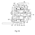
- the canned pump including a doubled-sided-supported stationary shaft without any monitor device as shown in FIG. 1A and 3A .
- Fig. 1A is a cross-sectional view of a double-sided-supported stationary shaft without any monitor device of the canned pump according to the present invention
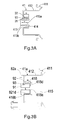
- Fig. 3A is a cross-sectional view of a containment shell of a double-sided-supported stationary shaft of the canned pump according to the present invention.
- the canned pump comprises: a pump casing 4, a triangle front support 31, a type I impeller 5, a type I containment shell 41, a stationary shaft 3 and a canned motor 8.
- the pump casing 4 includes an inlet 44, an outlet 45 and a flow channel 47, and is used for containing the type I impeller 5.
- a front thrust ring 46 installed on an inner side of the inlet 44 of the pump casing 4, is used for mating with a thrust bearing 53 of the type I impeller 5 to form an axial thrust bearing together.
- the type I impeller 5 is assembled in the pump casing 4.
- the triangle front support 31 may pass through the hub aperture 54 axially and is used for supporting the end of the stationary shaft 3.
- a hub plate 52 is used for combining an axially extended part 76 of an inner rotor 7 of the canned motor 8 so that the type I impeller 5 and the inner rotor 7 are integrated into one piece or embedded to be combined into one piece.
- the type I containment shell 41 is a cup-shaped shell structure with a blank rear shaft support 413 installed on a bottom side of the type I containment shell 41. There is no any through hole on the blank rear shaft support 413 with a ring slot 413b for ensuring there is no leakage from the type I containment shell 41.
- a shell flange part 411 installed on a front side of the type I containment shell 41, is combined with the pump casing 4 and a pump side flange 811 of the canned motor 8 for preventing a corrosive fluid from leakage.
- a motor rear casing 82 of the canned motor 8 is tightly attached on the bottom side of the type I containment shell 41 with sufficient supporting strength.
- the blank rear shaft support 413 is installed at the center of the bottom side of the type I containment shell 41 and extends inwardly and axially to an inner space of a rotor yoke 72.
- the blank rear shaft support 413 includes a shaft hold hole 413a protruding inwardly and positioned in the blank rear shaft support 413, and includes a ring slot 413b installed on the outer side of the blank rear shaft support 413.
- a rear thrust ring 414 is installed on front surface of the shaft hold hole 413a and is used for mating with a ceramic bearing 79 of the inner rotor 7 to form the axial thrust bearing.
- An outer sidewall surface of the shaft hold hole 413a is completely combined with and supported by a shaft metal rear support 821a of the motor rear casing 82, and a bottom side of the shaft hold hole 413a is completely fitted with the inner side of a backward bulged part 823 of the motor rear casing 82, and the length of the bulged part 823 is fitted with the depth H of the shaft hold hole 413a for providing the high-stiff support for the stationary shaft 3, and hereafter this kind of structure is called a metal holding support.
- the type I containment shell 41 is only used for providing anti-corrosion isolating property without providing stiff support for the stationary shaft 3.
- the stationary shaft 3 which is a double-sided supported structure, is made of a ceramic material with anti-corrosion and anti-wear properties.
- a front side of the stationary shaft 3 is supported by the triangle front support 31 and a rear side of the stationary shaft 3 is supported by the blank rear shaft support 413 which extends outwardly.
- a center portion of the stationary shaft 3 mates with the ceramic bearing 79 for supporting the rotation of the inner rotor 7, and the length of the center portion of the stationary shaft 3 satisfies the length of ceramic bearing 79 so that the length of the center portion is favorable for withstanding a composite force which is borne by the inner rotor 7 and reserving an axial free-movement space for the inner rotor 7.
- the ring slot 413b of the blank rear shaft support 413 is tightly combined with and supported by the shaft metal rear support 821a of the motor rear casing 82 and provides a hold length L. Moreover, the ring slot 413b may overcome the problem of the reduced strength of plastic material due to the rise of the temperature.
- the canned motor 8 comprises the stator 83, a motor casing 81, a motor rear casing 82 and the inner rotor 7.
- the stator 83 is tightly fixed in the motor casing 81. Windings 831 are winded on the stator 83. A PWM electric power, applied on the windings 831, generates a magnetic flux to interact with a magnetic field of the inner rotor 7, the inner rotor 7 generates torque and rotates to drive the type I impeller 5 to output hydraulic power.
- the type I containment shell 41 prevents the windings 831 of the stator 83 from being corroded by the corrosive fluid.
- the pump side flange 811 of the motor casing 81 is used for tightly fixing with the shell flange part 411 and the pump casing 4 to prevent the leakage from the corrosive fluid.
- a back flange of the motor casing 81 is used for fixing the motor rear casing 82 to provide a complete structure support so that the shaft metal rear support 821a of the motor rear casing 82 may provide support needed by the stationary shaft 3.
- the motor rear casing 82 is fixed with the back flange of the motor casing 81 so that the shaft metal rear support 821a of the motor rear casing 82 may provide support needed by the stationary shaft 3.
- An electric power wire of the windings 831 of the stator 83 is connected to a drive power via a lead port 822.
- the inner rotor 7 is a ring-shaped structure comprising main magnets 71, the rotor yoke 72 and the axially extended part 76 and forming a ring-shaped rotor resin enclosure 74 covered with an engineering plastic with anti-corrosion property.
- a ceramic bearing 79 is installed in a central hole of the inner rotor 7.
- the hub plate 52 is used for combining with the axially extended part 76 of the inner rotor 7 so that the type I impeller 5 and the inner rotor 7 are integrated into one piece or embedded to be combined with each other into one piece.
- fluid flows along an inlet streamline 6 and is pressurized after flowing through the type I impeller 5, such as an impeller exit streamline 61.
- the pressurized fluid is output by an outlet 45 and a portion of the fluid, such as a turn back streamline 62, enters the inner space 415 of the type I containment shell 41 via a rear side of the type I impeller 5.
- the fluid flows to the gap between an outer side of the inner rotor 7 and the inner space 415 of the type I containment shell 41, continuing through another gap between the stationary shaft 3 and the ceramic bearing 79.
- the fluid flows through the hub aperture 54, such as an end lubrication streamline 65, to an inlet of the type I impeller 5.
- the circulating flowing of the fluid is used for providing the lubrication for the ceramic bearing 79 and taking away the heat generated by the inner rotor 7.
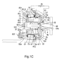
- the canned pump including a singled-sided-supported cantilever composited stationary shaft without any monitor device which is shown as in FIG. 1C , Fig. 3B and Fig.5B .
- Fig. 1Ac is a cross-sectional view of a single-sided-supported cantilever composited stationary shaft without any monitor device of the canned pump according to the present invention
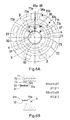
- Fig. 3B is a cross-sectional view of a containment shell of a cantilever stationary shaft of the canned pump according to the present invention
- Fig. 5B shows an inner rotor bearing multiple forces and moments thereof on a single-sided-supported cantilever stationary shaft according to the present invention.
- the canned pump comprises a metal casing 4a, a type II impeller 5a, a type II containment shell 41a, a composited stationary shaft 3a and a canned motor 8.
- the metal casing 4a which includes an inlet 44, an outlet 45 and a flow channel 47 is used for containing the type II impeller 5a.
- the metal casing 4a is a metal wok structure by casting.
- a casing liner 4b made of anti-corrosive plastic, is covered on an inner side of the metal casing 4a.
- a front thrust ring 46 installed at the inlet 44 in an inner side of the metal casing 4a, is used for mating with a thrust bearing 53 of the type II impeller 5a to form an axial thrust bearing.
- the type II impeller 5a is installed in the metal casing 4a.
- a hub plate 52 is used for being combined with an axially extended part 76 of an inner rotor 7 so that the type II impeller 5a and the inner rotor 7 are integrated into one piece or embedded with each other into one piece.
- a hub balance hole 54a is a aperture at the center of a curve hub plate 55 for making circulating fluid re-circulate, for example, an end lubrication streamline 65.
- the inlet 44 of the metal casing 4a and the inlet of the type II impeller 5a form a smooth and increasing- inner-diameter channel without any disturbance, and the shape of the curve hub plate 55 is smooth curve shape as well. Therefore, it is favorable for reducing the flow speed of the fluid to make sure the pump has good NPSHr ability.
- the type II containment shell 41a is a cup-shaped structure which has a rear shaft seat 418 including a hole installed on a bottom side of the type II containment shell 41a.
- a shell flange part 411 installed on a front side of the type II containment shell 41a, is combined with the metal casing 4a and a pump side flange 811 of the canned motor 8, which prevents the fluid from leakage.
- a shell column part 412 installed on a lateral side of the type II containment shell 41a, passes through the inner side of the stator 83 with a loose slide fit. Also, the bottom side of the type II containment shell 41a is tightly attached to the motor rear casing 82 with sufficient supporting strength..
- the rear shaft seat 418 installed on the center on the bottom side of the type II containment shell 41a, extends inwardly towards the inner space of the rotor yoke 72, and the rear shaft seat 418 further protrudes inwardly and includes an aperture 418a installed at an inner side of the rear shaft seat 418 and a concave aperture 418b installed on an outer side of the rear shaft seat 418 corresponding to each other, and the aperture, installed on the center of the rear shaft seat 418, is used for containing the composited stationary shaft 3a, and a seal surface 418d of the rear shaft seat 418 is tightly attached by a surface of a ceramic shaft sleeve 33 including an O ring and a shaft metal rear support 821a of the motor rear casing 82, and hereafter this kind of structure is called metal composited support, which may make sure that there is no leakage.
- This embodiment does not have any monitor device to provide a detection device for detecting the wear of the bearing.
- the composited stationary shaft 3a which is a cantilever supported structure, is made of a ceramic shaft sleeve33, a metal shaft 32 and a motor rear casing 82 with anti-corrosion and anti-wear properties.
- the composited stationary shaft 3a and the type II containment shell 41a form a completely sealed shaft system.
- the metal shaft 32 passes through a sleeve central hole 332 of the ceramic shaft sleeve 33, and includes a circular head 321 which is installed at an end of the metal shaft 32 and pressed tightly against a front end surface 333 of the ceramic shaft sleeve 33.
- a teeth part 323 of the metal shaft 32 passes through the rear shaft seat 418 of the type II containment shell 41a and a central hole of the composited shaft metal rear support 821c which is extended inwardly in a radial direction.
- a nut of the teeth part 323 is fixed on the motor rear casing 82a so that a sliding thrust surface 331 of the ceramic shaft sleeve 33 is tightly pressed against a surface of the composited shaft metal rear support 821c.
- a circular head 321 of the metal shaft 32 is covered with a resin enclosure 322, and an O ring is installed on the circular head 321 which is used for sealing and corrosion resistance.
- the sliding thrust surface 331 of the ceramic shaft sleeve 33 is used for mating with a ceramic bearing 79 of the inner rotor 7 to form an axial thrust bearing.
- a surface of the sliding thrust surface 331 and a surface of the composited shaft metal rear support 821c of the motor rear casing 82a are tightly fixed and compressed with each other and a seal surface 418d of the rear shaft seat 418, packed tightly and installed between the sliding thrust surface 331 and the composited shaft metal rear support 821c is encapsulated by a surface of the sliding thrust surface 331 including another O ring, which makes sure there is no leakage, thereby forming a composited stationary shaft 3a with high stiffness.
- the canned motor 8 comprises the stator 83, a motor casing 81, a motor rear casing 82a and an inner rotor 7.
- the stator 83 is tightly fixed in the motor casing 81. Windings 831 are winded on the stator 83. A PWM electric power, applied on the windings 831, may generate a magnetic flux to interact with a magnetic field of the inner rotor 7, so the inner rotor 7 generates torque and rotates to drive the type II impeller 5a to output hydraulic power.
- the type II containment shell 41a prevents the windings 831 of the stator 83 from being corroded by the corrosive fluid.
- the pump side flange 811 which is installed on a lateral pump side of the motor casing 81 is used for fixing with the shell flange part 411 and the metal casing 4a for preventing corrosive fluid from leakage.
- a back flange of the motor casing 81 is used for fixing with the motor rear casing 82a to provide a complete structure support so that the composited shaft metal rear support 821c of the motor rear casing 82a may provide support which is required by the composited stationary shaft 3a.
- the motor rear casing 82a is tightly fixed with the back flange of the motor casing 81 so that the composited shaft metal rear support 821c of the motor rear casing 82a may provide support which is required by the composited stationary shaft 3a.
- An electric power wire of the windings 831 of the stator 83 is connected to a drive power via a lead port 822.
- the inner rotor 7 is a ring-shaped structure comprising main magnets 71, a rotor yoke 72 and an axially extended part 76 and forming a ring-shaped rotor resin enclosure 74 which is covered with an engineering plastic with anti-corrosion property.
- a ceramic bearing 79 is installed in a central hole of the inner rotor 7.
- the hub plate 52 is used for combining with the axially extended part 76 of the inner rotor 7 so that the type II impeller 5a and the inner rotor 7 are integrated into one piece or embedded to be combined with each other into one piece.
- fluid flows along an inlet streamline 6 and is pressurized after flowing through the type II impeller 5a, such as an impeller exit streamline 61.
- the pressurized fluid is output by an outlet 45, and a portion of the fluid, such as a turn back streamline 62, enters the inner space 415 of the type II containment shell 41a via a rear side of the type II impeller 5a in the mean time.
- the fluid flows to the gap between an outer side of the inner rotor 7 and the inner space 415 of the type II containment shell 41a, continuing through another gap between of the composited stationary shaft 3a and the ceramic bearing 79.
- the fluid flows through a hub balance hole 54a which is installed at the center of the curve hub plate 55, such as an end lubrication streamline 65, to an inlet of the type II impeller 5a.
- the circulating flowing of the fluid is used for providing the lubrication for the ceramic bearing 79 and taking away the heat generated by the inner rotor 7.
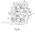
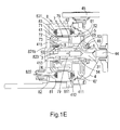
- the canned pump including a doubled-sided-supported cantilever composited stationary shaft and a monitor device shown in FIGs. 1B , 1E and Fig. 3A .
- Fig. 1B is a cross-sectional view of a double-sided supported stationary shaft with a monitor device of the canned pump according to the present invention
- Fig. 1E is a cross-sectional view of a double-sided-supported stationary shaft with a monitor device and with a lengthened bearing of the canned pump according to the present invention
- Fig. 3A is a cross-sectional view of a containment shell of a double-sided-supported stationary shaft of the canned pump according to the present invention.
- the canned pump comprises a pump casing 4, a triangle front support 31, a type I impeller 5, a type I containment shell 41, a monitor device 9, a stationary shaft 3 and a canned motor 8.
- the pump casing 4 includes an inlet 44, an outlet 45 and a flow channel 47, and is used for containing the type I impeller 5.
- a front thrust ring 46 is installed on an inner side of the inlet 44 of the pump casing 4 and used for mating with a thrust bearing 53 of the type I impeller 5 to form an axial thrust bearing together.
- the triangle front support 31 is fixed on the inlet 44 of the pump casing 4, passes through a hub aperture 54 axially and is used for supporting an end of the stationary shaft 3.
- the type I impeller 5 is assembled in the pump casing 4.
- the triangle front support 31 may pass through the hub aperture 54 axially and is used for supporting the end of the stationary shaft 3.
- a hub plate 52 is used for combining an axially extended part 76 of an inner rotor 7 of the canned motor 8 so that the type I impeller 5 and the inner rotor 7 are integrated into one piece or embedded to be combined into one piece.
- the type I containment shell 41 is a cup-shaped shell structure comprising a blank rear shaft support 413 installed on a bottom side of the type I containment shell 41. There is no any through hole on the blank rear shaft support 413 with a ring slot 413b for ensuring there is no leakage from the type I containment shell 41.
- a shell flange part 411 installed on a front side of the type I containment shell 41, is combined with the pump casing 4 and a pump side flange 811 of the canned motor 8 for preventing a corrosive fluid from leakage.
- a motor rear casing 82 of the canned motor 8 is tightly attached on the bottom side of the type I containment shell 41 with sufficient support strength.
- the blank rear shaft support 413 is installed at the center of the bottom side of the type I containment shell 41 and extends inwardly and axially to an inner space of a rotor yoke 72.
- the blank rear shaft support 413 includes a center shaft hold hole 413a protruding inwardly, and the ring slot 413b is on the outer side of the blank rear shaft support 413.
- a rear thrust ring 414 is installed on front surface of the shaft hold hole 413a and is used for mating with a ceramic bearing 79 of the inner rotor 7 to form an axial thrust bearing.
- the monitor set 93 which includes a secondary yoke 91 and multiple signal coil pairs 92, is installed on the monitoring shaft metal rear support 821b of the motor rear casing 82, and put into the ring slot 413b of outer sidewall surface of the shaft hold hole 413a..
- a bottom side of the blank rear shaft support 413 is completely fitted with the inner side of a bulged part 823 of the motor rear casing 82.
- the length of the bulged part 823 is fitted with the depth H of the shaft hold hole 413a for providing the high-stiff support of the stationary shaft 3.
- the type I containment shell 41 is only used for providing anti-corrosion isolating ability without providing stiff support for the stationary shaft 3.
- the structure of the monitor device 9 comprises multiple secondary magnets 73 and a monitor set 93.
- the number of the secondary magnets 73 is the same as the main magnets 71.
- the secondary magnets 73 are assembled at one end of the inner side of a rotor yoke 72 of the inner rotor 7 in the vicinity of the bottom side of the type I containment shell 41 as well as face oppositely away from the main magnets 71.
- the axial length of the secondary magnets 73 is at least more than twice as great as the length of an axial movement (including the axial wear of the bearing) of the inner rotor 7.
- the monitor set 93 comprises the secondary yoke 91 (not shown) and the multiple signal coil pairs 92.
- the secondary yoke 91 take the position at the center of the secondary magnets 73 as a reference point, the axial length of the secondary yoke 91 is divided into two sections, a front section and a rear section. When the secondary magnets 73 are moved axially, both ends of the secondary magnets 73 do not exceed the ranges of the two sections of the secondary yoke 91.
- the stationary shaft 3 is the doubled-sided supported structure made of ceramic material with anti-corrosion and anti-wear properties.
- a front side of the stationary shaft 3 is supported by the triangle front support 31 and a rear side of the stationary shaft 3 is supported by the blank rear shaft support 413 which extends outwardly.
- a center portion of the stationary shaft 3 mates with the ceramic bearing 79 for supporting the rotation of the inner rotor 7, and the length of the center portion of the stationary shaft 3 satisfies the length of ceramic bearing 79 and reserves an axial free-movement space for the inner rotor 7.
- the ring slot 413b of the blank rear shaft support 413 is tightly combined with and supported by the monitoring shaft metal rear support 821b of the motor rear casing 82 and provides a hold length L. Moreover, the ring slot 413b may overcome the problem of the reduced strength of plastic material due to the rising of the temperature.
- the canned motor 8 comprises the stator 83, a motor casing 81, the motor rear casing 82 and the inner rotor 7.
- the stator 83 is tightly fixed in the motor casing 81. Windings 831 are winded on the stator 83. A PWM electric power, applied on the windings 831, generates a magnetic flux to interact with a magnetic field of the inner rotor 7. The inner rotor 7 generates torque and rotates to drive the type I impeller 5 to output hydraulic power. The type I containment shell 41 prevents the windings 831 of the stator 83 from being corroded by the corrosive fluid.
- the pump side flange 811 of the motor casing 81 is used for tightly fixing with the shell flange part 411 and the pump casing 4 to prevent the leakage from the corrosive fluid.
- a back flange of the motor casing 81 is used for fixing the motor rear casing 82 to provide a complete structure supporting so that the monitoring shaft metal rear support 821b of the motor rear casing 82 may provide supporting needed by the stationary shaft 3.
- the motor rear casing 82 is fixed with the motor casing 81 so that the monitoring shaft metal rear support 821b, on the motor rear casing 82, may provide supporting needed by the stationary shaft 3.
- An electric power wire of the windings 831 of the stator 83 is connected to a drive power via a lead port 822.
- the inner rotor 7 is a ring-shaped structure comprising the main magnets 71, the rotor yoke 72, the secondary magnets 73 and the axially extended part 76.
- the number of the secondary magnets 73 is the same as the main magnets 71.
- the secondary magnets 73 are assembled at one end of the inner side of a rotor yoke 72 of the inner rotor 7 in the vicinity of the bottom side of the type I containment shell 41 as well as face oppositely away from the main magnets 71.
- a ceramic bearing 79 is installed in a central hole of the inner rotor 7.
- the hub plate 52 is used for combining with the axially extended part 76 of the inner rotor 7 so that the type I impeller 5 and the inner rotor 7 are integrated into one piece or embedded to be combined with each other into one piece.
- fluid flows along an inlet streamline 6 and is pressurized after flowing through the type I impeller 5, such as an impeller exit streamline 61.
- the pressurized fluid is output by an outlet 45 and a portion of the fluid, such as a turn back streamline 62, enters the inner space 415 of the type I containment shell 41 via a rear side of the type I impeller 5.
- the fluid flows to the gap between an outer side of the inner rotor 7 and the inner space 415 of the type I containment shell 41, continuing through another gap between the stationary shaft 3 and the ceramic bearing 79.
- the fluid flows through the hub aperture 54, such as an end lubrication streamline 65, to an inlet of the type I impeller 5.
- the circulating flowing of the fluid is used for providing the lubrication for the ceramic bearing 79 and taking away the heat generated by the inner rotor 7.
- FIG. 1E is a cross-sectional view of a double-sided-supported stationary shaft with a monitor device and a lengthened bearing of the canned pump according to the present invention.
- This embodiment discloses the canned pump with a lengthened ceramic bearing 79 for heavy duty operation. Therefore, in the structure design of the pump, the length of the rotor yoke 72 may be lengthened properly to meet with the length of the ceramic bearing 79.
- the canned pump including a singled-sided-supported cantilever composited stationary shaft and a monitor device shown as in FIG. 1D , 3B , 4B and 5B .
- Fig. 1D is a cross-sectional view of a single-sided-supported cantilever composited stationary shaft with a monitor device of the canned pump according to the present invention
- Fig. 3B is a cross-sectional view of a containment shell of a cantilever stationary shaft of the canned pump according to the present invention
- Fig. 4B shows an axial hold length L of a cantilever stationary shaft according to the present invention
- Fig. 5B shows a inner rotor bearing multiple forces and moments thereof on a single-sided-supported cantilever stationary shaft according to the present invention.
- the canned pump comprises a metal casing 4a, a type II impeller 5a, a type II containment shell 41a, a monitor device 9, a composited stationary shaft 3a and a canned motor 8.
- the metal casing 4a which includes an inlet 44, an outlet 45 and a flow channel 47 is used for containing the type II impeller 5a.
- the metal casing 4a is a metal wok structure by casting.
- a casing liner 4b made of anti-corrosive plastic, is covered on an inner side of the metal casing 4a.
- a front thrust ring 46 installed at the inlet 44 in an inner side of the metal casing 4a, is used for mating with a thrust bearing 53 of the type II impeller 5a to form an axial thrust bearing.
- the type II impeller 5a is installed in the metal casing 4a.
- a hub plate 52 is used for being combined with an axially extended part 76 of an inner rotor 7 so that the type II impeller 5a and the inner rotor 7 are integrated into one piece or embedded with each other into one piece.
- a hub balance hole 54a is a through hole at the center of a curve hub plate 55 for making circulating fluid re-circulate, for example, an end lubrication streamline 65.
- the inlet 44 of the metal casing 4a and the inlet of the type II impeller 5a form a smooth and increasing- inner-diameter channel without any disturbance, and the shape of the curve hub plate 55 is smooth curve shape as well. Therefore, it is favorable for reducing the flow speed of the fluid to make sure the pump has good NPSHr ability.
- the type II containment shell 41a is a cup-shaped structure which has a rear shaft seat 418 including an aperture on a bottom side of the type II containment shell 41a.
- a shell flange part 411, on a front side of the type II containment shell 41a, is combined with the metal casing 4a and a pump side flange 811 of the canned motor 8, which prevents corrosive fluid from leakage.
- a shell column part 412 on a lateral side of the type II containment shell 41a is passed through the inner side of the stator 83 with a loose slide fit. Also, the bottom side of the type II containment shell 41a is tightly attached to the motor rear casing 82a with sufficient supporting strength.
- the rear shaft seat 418 on the center on the bottom side of the type II containment shell 41a, extends inwardly towards the inner side of a rotor yoke 72.
- the rear shaft seat 418 further protrudes inwardly and includes an aperture 418a installed at an inner side of the rear shaft seat 418 and a concave aperture 418b installed on an outer side of the rear shaft seat 418 corresponding to each other.
- the aperture, installed on the center of the rear shaft seat 418, is used for containing the composited stationary shaft 3a.
- a seal surface 418d of the rear shaft seat 418 is tightly attached by a surface of a ceramic shaft sleeve 33 including an O ring and a monitoring composited shaft metal rear support 821d of the motor rear casing 82a so that there is no leakage.
- the monitor device 9 positioned on a ring-shaped surface of the concave aperture 418b of the rear shaft seat 418 which extends axially, is used for detecting the wear of a bearing.
- the structure of the monitor device 9 comprises multiple secondary magnets 73 and a monitor set 93.
- the number of the secondary magnets 73 is the same as the main magnets 71.
- the secondary magnets 73 are assembled at one end of the inner side of a rotor yoke 72 of the inner rotor 7 in the vicinity of the bottom side of the type I I containment shell 41a as well as face oppositely away from the main magnets 71..
- the axial length of the secondary magnets 73 is at least more than twice as great as the length of an axial movement (including the axial wear of the bearing) of the inner rotor 7.
- the monitor set 93 comprises the secondary yoke 91 and multiple signal coil pairs 92.
- the secondary yoke 91 take the position at the center of the secondary magnets 73 as a reference point, the axial length of the secondary yoke 91 is divided into two sections, a front section and a rear section. When the secondary magnets 73 are moved, two axial ends of the secondary magnets 73 do not exceed the ranges of the two sections of the secondary yoke 91.
- the composited stationary shaft 3a which is a cantilever supported structure, comprises a ceramic shaft sleeve 33, a metal shaft 32 and a motor rear casing 82a.
- the composited stationary shaft 3a and the type II containment shell 41a form a completely sealed shaft system.
- a required supporting strength is provided.
- the metal shaft 32 passes through a sleeve central hole 332 of the ceramic shaft sleeve 33 with the circular head 321 of the metal shaft 32 pressed tightly against the front end surface 333 of the ceramic shaft sleeve 33.
- the teeth part 323 of the metal shaft 32 passes through to the rear shaft seat 418 and a central hole of the monitoring composited shaft metal rear support 821d of the type II containment shell 41a which is extended inwardly in an axial direction.
- a nut of the teeth part 323 is fixed on the motor rear casing 82a so that a surface of a sliding thrust surface 331 of the ceramic shaft sleeve 33 is tightly pressed against a surface of the monitoring composited shaft metal rear support 821d.
- a circular head 321 of the metal shaft 32 is covered with a resin enclosure 322, and an O ring is installed on the circular head 321 which is used for sealing and corrosion resistance.
- the sliding thrust surface 331 of the ceramic shaft sleeve 33 is used for mating with the ceramic bearing 79 of the inner rotor 7 to form an axial thrust bearing.
- a surface of the sliding thrust surface 331 and a surface of the monitoring composited shaft metal rear support 821d of the motor rear casing 82a are tightly fixed and compressed with each other, and a seal surface 418d of the rear shaft seat 418 packed tightly between the sliding thrust surface 331 and the monitoring composited shaft metal rear support 821d, and press an O ring to make sure there is no leakage, thereby forming a composited stationary shaft 3a with high stiffness.
- the canned motor 8 comprises the stator 83, a motor casing 81, the motor rear casing 82a and the inner rotor 7.
- the stator 83 is tightly fixed in the motor casing 81. Windings 831 are winded on the stator 83. A PWM electric power, applied on the windings 831, may generate a magnetic flux to interact with a magnetic field of the inner rotor 7, so the inner rotor 7 generates torque and rotates to drive the type II impeller 5a to output hydraulic power.
- the type II containment shell 41a prevents the windings 831 of the stator 83 from being corroded by the corrosive fluid.
- the pump side flange 811 which is fixed on a lateral pump side of the motor casing 81 and also fixing the shell flange part 411 and the metal casing 4a for preventing the corrosive fluid from leakage.
- a back flange of the motor casing 81 is used for fixing with the motor rear casing 82a to provide a complete structure supporting so that the monitoring composited shaft metal rear support 821d of the motor rear casing 82a may provide support which is required by the composited stationary shaft 3a.
- the motor rear casing 82a is tightly fixed with the back flange of the motor casing 81 so that the monitoring composited shaft metal rear support 821d of the motor rear casing 82a may provide support which is required by the composited stationary shaft 3a.
- An electric power wire of the windings 831 of the stator 83 is connected to a drive power via a lead port 822.
- the inner rotor 7 is a ring-shaped structure comprising the multiple main magnets 71, a rotor yoke 72, multiple secondary magnets 73 and the axially extended part 76.
- the number of the secondary magnets 73 is the same as the main magnets 71.
- the secondary magnets 73 are assembled at one end of the inner side of a rotor yoke 72 of the inner rotor 7 in the vicinity of the bottom side of the type I containment shell 41 as well as face oppositely away from the main magnets 71.
- the secondary magnets 73 is covered by a ring-shaped rotor resin enclosure 74 which is made of an engineering plastic with anti-corrosion property.
- a ceramic bearing 79 is installed in a central hole of the inner rotor 7.
- the hub plate 52 is used for combining with the axially extended part 76 of the inner rotor 7 so that the type II impeller 5a and the inner rotor 7 are integrated into one piece or embedded to be combined with each other into
- fluid flows along an inlet streamline 6 and is pressurized after flowing through the type II impeller 5a, such as an impeller exit streamline 61.
- the pressurized fluid is output by an outlet 45, and a portion of the fluid, such as a turn back streamline 62, enters the inner space 415 of the type II containment shell 41a via a rear side of the type II impeller 5a in the mean time.
- the fluid flows to the gap between an outer side of the inner rotor 7 and the inner space 415 of the type II containment shell 41a, continuing through another gap between of the composited stationary shaft 3a and the ceramic bearing 79.
- the fluid flows through a hub balance hole 54a which is at the center of the curve hub plate 55, such as an end lubrication streamline 65, to an inlet of the type II impeller 5a.
- the circulating flowing of the fluid is used for providing the lubrication for the ceramic bearing 79 and taking away the heat generated by the inner rotor 7.
- FIG. 2 is a cross-sectional view of an inner rotor 7 of a motor and a type I impeller 5 integrated into one unit according to the third embodiment.
- the structure in this embodiment is also applicable to other embodiments in this invention.
- the ceramic bearing 79 installed in a hollow part of the inner rotor 7, is used for mating with the stationary shaft 3 to form a hydrodynamic bearing which is used for supporting the rotation of the inner rotor 7 and transmitting the motor power.
- the axially extended part 76 is used for being combined with the hub plate 52 to transmit the torque of the inner rotor 7.
- the secondary magnets 73 are assembled at one end of the inner side of a rotor yoke 72 of the inner rotor 7 as well as face oppositely away from the main magnets 71.
- the secondary magnets 73 and the inner rotor 7 are encapsulated together for preventing corrosion.
- the number of the secondary magnets 73 is the same as the main magnets 71 but the size of the secondary magnets 73 is less than one tenth of the main magnets 71.
- FIG. 3A is a cross-sectional view of a containment shell of a double-sided-supported stationary shaft of the canned pump according to the present invention.
- the type I containment shell 41 is a cup-shaped structure without any through hole so that there is no leakage.
- the blank rear shaft support 413 at the center of the bottom side of the type I containment shell 41 extends inwardly.
- the axially extended length G is extended from the bottom side of the type I containment shell 41 towards the shell flange part 411.
- the blank rear shaft support 413 protrudes from the inner side and has the central shaft hold hole 413a whose depth H is from the opening of the blank rear shaft support 413 to the bottom side of the shaft hold hole 413a.
- the ring slot 413b is on the outer side of the type I containment shell 41.
- the rear thrust ring 414 is on the front surface of the shaft hold hole 413a.
- the monitor set 93 including the secondary yoke 91 and the signal coil pairs 92, may be positioned on the ring slot 413b which is on the outer side of the blank rear shaft support 413.
- the type I containment shell 41 is only used for providing anti-corrosion isolating ability without providing stiff supporting for the stationary shaft 3
- FIG. 3B is a cross-sectional view of a containment shell of a cantilever stationary shaft of the canned pump according to the present invention.
- the type II containment shell 41a of the fourth embodiment Take the type II containment shell 41a of the fourth embodiment as an example. The assembly of the concave aperture 418b and the monitor set 93 are described as followed.
- the type II containment shell 41a is a cup-shaped shell structure comprising a hole which is on the center of the bottom side and is used for containing the composited stationary shaft 3a (shown in Fig. 1C ).
- the rear shaft seat 418 on the center on the bottom side of the type II containment shell 41a extends inwardly in the inner space.
- the rear shaft seat 418 is a convex structure having an aperture 418a and protruding from the inner side.
- the axially extended length G extends from the bottom side of the type II containment shell 41a towards the shell flange part 411 to the seal surface 418d.
- the outer side of the rear shaft seat 418 corresponds to the concave aperture 418b.
- the monitor set 93 positioned on an inner ring-shaped surface of the concave aperture 418b, includes the secondary yoke 91 and the multiple signal coil pairs 92.
- the secondary yoke 91 is tightly attached to the monitoring composited shaft metal rear support 821d.
- the composited stationary shaft 3a (shown in Fig. 1C ) is installed in the aperture which is at the center of the rear shaft seat 418.
- the seal surface 418d of the rear shaft seat 418 is tightly pressed by the surface of the surface of the sliding thrust surface 331 of the ceramic shaft sleeve 33 (shown in Fig. 1C ) including the O ring and the monitoring composited shaft metal rear support 821d of the motor rear casing 82a, which makes sure that there is no leakage from the type II containment shell 41a.
- the stiffness support of the composited stationary shaft 3a is completely comes from the motor rear casing 82a and the hold length L of the monitoring composited shaft metal rear support 821d.
- FIG. 4A shows an axial hold length L of a double-sided-supported stationary shaft according to the present invention.
- the axial hold length L is described as followed.
- the blank rear shaft support 413 is positioned at the center of the bottom side of the type I containment shell 41 and extends inwardly and axially to an inner space of the rotor yoke 72 (shown in Fig. 1A ).
- the blank rear shaft support 413 includes the shaft hold hole 413a (shown in Fig. 3A ) protruding inwardly and positioned in the blank rear shaft support 413, and the ring slot 413b (shown in Fig.
- the monitor set 93 which includes the secondary yoke 91 and the signal coil pairs 92, is installed in the ring slot 413b (shown in Fig. 3A ).
- the strength of the shaft hold hole 413a (shown in Fig. 3A ), which is supported by the monitoring shaft metal rear support 821b of the motor rear casing 82 and the secondary yoke 91 tightly combined to each other,. is provided by the outer sidewall of the haft hold hole 413a
- the bottom side of the shaft hold hole 413a is completely fitted with the inner side of the backward bulged part 823 of the motor rear casing 82.
- the length of the bulged part 823 is fitted with the hold length L of the shaft hold hole 413a for providing the high-stiff support. That is, the type I containment shell 41 is only used for providing anti-corrosion isolating ability without providing stiff support for the stationary shaft 3.
- the hold length L is determined by the axially extended length G of the blank rear shaft support 413 and the hold hole depth H so that the axial stiff support may be practically provided.
- FIG. 4B shows an axial hold length L of a cantilever stationary shaft according to the present invention.
- the type II containment shell 41a which is the cup-shaped shell structure includes the rear shaft seat 418 positioned at the center of the bottom side, extending inwardly and axially in the inner space of the rotor yoke 72, and for containing the composited stationary shaft 3a (shown in Fig. 1C ).
- the rear shaft seat 418 is a convex structure having an aperture 418a and protruding from the inner side and is a concave aperture 418b at the outer side.
- the monitor set 93 is installed on the inner ring-shaped surface of the concave aperture 418b.
- the seal surface 418d of the rear shaft seat 418 is tightly pressed by the surface of the surface of the sliding thrust surface 331 of the ceramic shaft sleeve 33 (shown in Fig. 1C ) including the O ring and the monitoring composited shaft metal rear support 821d of the motor rear casing 82a
- the composited stationary shaft 3a structure according to the invention may avoid the problem that the strength of the plastic material of the type II containment shell 41a may be reduced due to the rise of the temperature.
- FIG. 5A shows an inner rotor bearing multiple forces and moments thereof on a double-sided-supported stationary shaft according to the present invention.
- the stationary shaft 3 is made of anti-corrosion and anti-wear ceramic material.
- the front end of the stationary shaft 3 is supported by the plastic triangle front support 31, and the rear end of the stationary shaft 3 is supported and fixed by the blank rear shaft support 413 extending axially.
- the strength of the blank rear shaft support 413 is provided by the monitoring shaft metal rear support 821b and the secondary yoke 91 which are tightly combined with each other.
- the center portion of the stationary shaft 3 mates with the ceramic bearing 79, which is used for supporting the rotation of the inner rotor 7.
- the length of the center portion satisfies with the length of the ceramic bearing 79 and reserves the axial free-movement space of the inner rotor 7.
- A,B,C in the figure, When the inner rotor 7 actually rotates, A rear axial free space A exists between the ceramic bearing 79 and the rear thrust ring 414, a front axial free space C exists between the ceramic bearing 79 and the triangle front support 31, and an axial gap B exists between the inner rotor 7 and the type I containment shell 41.
- the above-mentioned gaps(spaces) may be varied due to the wear of surfaces of the front thrust ring 46, the thrust bearing 53, the rear thrust ring 414 and the ceramic bearing 79.
- the inner rotor 7 is moved forward because of the axial thrust by the type I impeller 5 to make the front thrust ring 46 mate with the thrust bearing 53 to slidably rotate.
- the axial width of the front axial free space C must be greater than the sum of the amount of wear allowance of the front thrust ring 46 and the thrust bearing 53, and the width of the axial gap B is increased accordingly when the front axial free space C is reduced.
- the inner rotor 7 may be moved backward because of the axial momentum of the fluid to make the rear thrust ring 414 mate with ceramic bearing 79 to slidably rotate and the width of the rear axial free space A is reduced to zero. Therefore, the width of the axial gap B must be greater than the total amount of the rear axial free space A, and the wear of the surface of the ceramic bearing 79 and the surface of the rear thrust ring, which prevents the inner rotor 7 from contacting the type I containment shell 41 directly, thereby resulting in the damage.
- the axial free-movement distance of the inner rotor 7 is equaled to the sum of the rear axial free space A and the front axial free space C, and because the amount of size deformation of the plastic type I containment shell 41 and the pump casing 4 is usually big, the reserved gap size must include manufacturing tolerance.
- the stationary shaft 3 and the supporting structure thereof must bear the multiple loading including an inner rotor weight W, an eccentric centrifugal force X, a radial force P and moments of these forces.
- the inner rotor weight W is the force generated by the weight of the inner rotor 7.
- the eccentric centrifugal force X is generated by the centroid of the inner rotor 7 resulted from the gaps of the ceramic bearing 79.
- the radial force P generated from the uneven fluid pressure of the flow channel 47 of the pump casing 4, applies on the outlet surface of the type I impeller 5.
- the weight moment is equaled to the inner rotor weight W multiplied by a weight arm length WL.
- the centrifugal moment is equaled to the eccentric centrifugal force X multiplied by an eccentric length XL.
- the moment of radial force is equaled to the radial force P multiplied by a radial force arm length PL.
- the eccentric centrifugal force X varying with the wearing of the ceramic bearing 79 is the most main variable loading applied on the stationary shaft 3.
- the second main variable loading applied on the stationary shaft 3 is the radial force P from the uneven fluid pressure of the outlet surface of the impeller 5.
- the longest radial force arm length is from the outer diameter of the impeller 5 to the rear end of the stationary shaft 3, which causes the skew between the center of the inner rotor 7 and the axis of the stationary shaft 3, thereby making the supporting structure deformed continuously. Because the axially extended length G substantially reduces the length of the radial force arm length, and the hold length L increases the moment bearing ability of the stationary shaft 3.
- the above-mentioned skew and structure deformation problem may be alleviated and improved, and therefore, the requirement for the strength of the supporting structure of the triangle front support 31 positioned at the front end of the stationary shaft 3 may be greatly reduced.
- FIG. 5B is an inner rotor bearing multiple forces and moments thereof on a single-sided-supported cantilever stationary shaft according to the present invention.
- the composited stationary shaft 3a is made of the metal shaft 32and the ceramic shaft sleeve 33.
- the metal shaft 32 passes through the sleeve central hole 332 of the ceramic shaft sleeve 33, and the end of the circular head 321 is tightly pressed against the front end surface 333 of the ceramic shaft sleeve 33.
- the teeth part 323 of the metal shaft 32 passes through the rear shaft seat 418 of the type II containment shell 41a and the central hole of the monitoring composited shaft metal rear support 821d, and is fixed with the motor rear casing 82 by the metal shaft 32.
- the surface of the sliding thrust surface 331 of the ceramic shaft sleeve 33 may be tightly pressed against the surface of the monitoring composited shaft metal rear support 821d so that the composited stationary shaft 3a with high stiffness is formed.
- the composited stationary shaft 3a whose length satisfies the length requirement for the ceramic bearing 79, mates with ceramic bearing 79 for supporting the rotation of the inner rotor 7, and reserves the axial free-movement space of the inner rotor 7, such as A, B.
- a rear axial free space A exists between the ceramic bearing 79 and the rear thrust ring 414
- an axial gap B exists between the inner rotor 7 and the type II containment shell 41a.
- the two above-mentioned gaps are varied because of the wearing of the front thrust ring 46, the thrust bearing 53, the rear thrust ring 414 and the ceramic bearing 79.
- the inner rotor 7 is moved forward by the axial thrust of the type II impeller 5a so that the front thrust ring 46 mates with the thrust bearing 53 to slidably rotate.
- the width of the axial gap B is increased accordingly.
- the inner rotor 7 is moved backward because of the axial momentum of the fluid, which makes the rear thrust ring 414 mate with the ceramic bearing 79 to slidably rotate and the width of the rear axial free space A is reduced to zero.
- the width of the axial gap B must be greater than the sum of the rear axial free space A and the amount of wear of the surface of the ceramic bearing 79 and the rear thrust ring 414, which prevents the inner rotor 7 from directly contacting the type II containment shell 41a, thereby causing the damage.
- the rear axial free space A is varied according to the axial free-movement of the inner rotor 7, because the amount of size deformation of the plastic type II containment shell 41a is usually big, each of the reserved gap sizes must include manufacturing tolerance.
- the composited stationary shaft 3a and the supporting structure thereof must bear the multiple loading including an inner rotor weight W, an eccentric centrifugal force X, a radial force P and moments of these forces.
- the inner rotor weight W is the force generated by the weight of the inner rotor 7.
- the eccentric centrifugal force X is generated by the centroid of the inner rotor 7 resulted from the gaps of the ceramic bearing 79.
- the radial force P generated from the uneven fluid pressure of the flow channel 47 of the metal casing 4a, applies on the outlet surface of the type II impeller 5a.
- the weight moment is equaled to the inner rotor weight W multiplied by a weight arm length WL.
- the centrifugal moment is equaled to the eccentric centrifugal force X multiplied by an eccentric length XL.
- the moment of the radial force is equaled to the radial force P multiplied by a radial force arm length PL.
- Those forces and moments apply on the composited stationary shaft 3a, and are borne by the metal composited support.
- the eccentric centrifugal force X varying with the wearing of the ceramic bearing 79 is the most main variable loading applied on the composited stationary shaft 3a. The greater the amount of the wear is, the greater the eccentric centrifugal force X is.
- the second main variable loading applied on the composited stationary shaft 3a is the radial force P from the uneven fluid pressure of the outlet surface of the impeller 5.
- the longest radial force arm length is from the outer diameter of the impeller 5 to the rear end of the composited stationary shaft 3a, which causes the skew between the center of the inner rotor 7 and the axis of the composited stationary shaft 3a, thereby making the supporting structure deformed continuously. Because the axially extended length G substantially reduces the length of the radial force arm length and the hold length L increases the moment bearing ability of the composited stationary shaft 3a, the above-mentioned skew and structure deformation problem may be alleviated and improved.
- the fifth embodiment a monitor device of the canned pump for detecting the wear of a bearing, FIGs. 6A, 6B , 6C , 6D .
- FIG. 6A is a radial cross-sectional view of a monitor device for detecting the wear of a bearing of a motor according to the present invention.
- the figure takes an eight-poles-and-eight-coils design for an example, but is not limited to the invention. Other designs or methods may achieve the same effect according other embodiments.
- a monitor device 9 comprises multiple secondary magnets 73 and a monitor set 93.
- the secondary magnets 73 are assembled at one end of the inner side of a rotor yoke 72 of the inner rotor 7 in the vicinity of the bottom side of the type I containment shell 41 as well as face oppositely away from the main magnets 71.
- the number of the secondary magnets 73 is the same as the main magnets 71 but the size of the secondary magnets 73 is less than one tenth of the main magnets 71, and the area and the thickness of the secondary magnets 73 at least provide the magnetomotive force (MMF) and the magnetic flux which are needed by the signal coil pairs.
- MMF magnetomotive force
- the circumference of the inner rotor 7 is divided into eight pieces according to the number of the secondary magnets 73 and each of them has an electric included angle of 180 degrees and a space included angle of 45 degrees.
- the main magnetic flux lines emits from a surface of a forward flux magnet 71a and passes through a motor magnetic gap 98 to a stator teeth 83a of a stator 83, continues to the adjacent stator teeth 83c via a stator yoke 83b, and passes through the motor magnetic gap 98 again, then to a original adjacent backward flux magnet 71b, and returns back to the original forward flux magnet 71a via the rotor yoke 72 so that the stator yoke magnetic route 96a is formed (hereafter called main magnetic loop)
- the secondary magnetic flux lines emit from a surface of the forward flux secondary magnet 73a to the secondary yoke 91 through the monitoring magnetic gap 97, and via a secondary yoke 92 pass through the monitoring magnetic gap 97 again, and back to
- the monitor set 93 comprises the secondary yoke 91 and the multiple signal coil pairs 92.
- the multiple signal coil pairs 92 installed on a surface of the secondary yoke 91, comprises front signal coil pairs 92a and rear coil pairs 92b which are axially and tightly arranged side by side and are aligned with a secondary magnet center 73g (shown in Fig. 6C ).
- the signal coil pairs 92 are divided into two groups of coils, signal coils ⁇ and signal coils ⁇ , along a circumferential direction.
- Each of the groups has two signal coil pairs, which are corresponding to each other in a radial direction of 180 degrees.
- Eight signal coils which include a signal coil ⁇ 11 , a signal coil ⁇ 12 , a signal coil ⁇ 21 , a signal coil ⁇ 22 , a signal coil ⁇ 11 , a signal coil ⁇ 12 , a signal coil ⁇ 21 , a signal coil ⁇ 22 , have the same size, and the difference between the electric included angle of the signal coils ⁇ and the signal coils ⁇ is 90 degrees (or 270 degrees) and the difference between the space included angle ⁇ of the signal coils ⁇ and the signal coils ⁇ is 112.5 degrees (or 67.5 degrees).
- the front signal coil pairs 92a comprise a signal coil ⁇ 11, a signal coil ⁇ 21 , a signal coil ⁇ 11 and a signal coil ⁇ 21 .
- the rear signal coil pairs 92b comprise a signal coil ⁇ 12 , a signal coil ⁇ 22 , a signal coil ⁇ 12 and a signal coil ⁇ 22 .
- the positioning of the electric included angles and the space included angles of the above-mentioned signal coil pairs 92 are obtained by a magnet alignment point 911 (shown in Fig. 6C ) of a secondary yoke rear end 91b of the secondary yoke 91.
- the magnet alignment point 911 aligns with the center of the signal coils ⁇ 11 , and when the electric included angle of the magnet alignment point 911 is 90 degrees and the space included angle of the magnet alignment point 911 is 22.5 degrees, it is favorable for repairing and exchanging the monitor set 93.
- the length of the ring-shape secondary yoke 91 of the independent monitor device 9 is longer than the sum of the axial length of the rotor yoke 72 and the axial movement length of the inner rotor 7, and is longer than the total axial length of the signal coil pairs 92 (including the limit value of the wear of thrust bearing).
- the width of the circumference of the signal coil pairs 92 is not greater than the electric included angle of 180 degrees.
- the secondary yoke front end 91a and the secondary yoke rear end 91b completely cover the signal coil pairs 92, which makes sure that when the inner rotor 7 is moved axially, the magnetic flux lines of the rotor yoke magnetic route 96 of the secondary magnets still can be stable as well as prevent the deformation and the bending, thereby ensuring the stability and the linearity of the voltage signal of the signal coil pairs 92.
- the differential voltage signals of the signal coil pairs 92 are obtained.
- the differential voltage signals of different combinations of the signal coil pairs may represent an axial movement or a radial movement.
- FIG. 6B is an axial cross-sectional view of a monitor device for detecting the wear of a bearing according to the present invention
- FIG. 6C is a schematic view of a monitor device for detecting the wear of a bearing utilizing eight signal coil pairs according to the present invention
- FIG. 6D is a schematic perspective view of a monitor device for detecting the wear of a bearing according to the present invention.
- the figures show an actual way of arranging signal coil pairs of a monitor device for detecting the wear of a bearing and a method for calculating the voltage signals.
- the figures take an eight-poles-and-eight-coils design for an example, but not limited to the invention.
- the monitor device 9 comprises eight signal coil pairs 92, which include a signal coil ⁇ 11 , a signal coil ⁇ 12 , a signal coil ⁇ 21 , a signal coil ⁇ 22 , a signal coil ⁇ 11 , a signal coil ⁇ 12 , a signal coil ⁇ 21 , a signal coil ⁇ 22 .
- ⁇ r is the rotation speed
- ⁇ mT is a flux linkage between the secondary magnets 73 and the signal coil pairs 92
- ⁇ r-f is the relative angular positions of the secondary magnets between ⁇ and ⁇ signal coils of the monitor device 9.
- the value of the eccentric movement and the angular position of the inner rotor 7, that is, the actual movement track of the inertial center of the inner rotor, can be calculated according to the above-mentioned equations.
- the sixth Embodiment a monitor device for detecting the wear of a bearing of the canned pump, FIG. 6E .
- FIG. 6E is a schematic view of a monitor device for detecting the wear of a bearing utilizing two pairs of signal coils according to the present invention.
- the number of signal coil pairs 92 of monitor device 9 for detecting the wear of a bearing is reduced to four according to this embodiment.
- the figure takes an eight-poles-and-four-coils design for an example, but is not limited to the invention. Other designs or methods may achieve the same effect according other embodiments.
- the area and the thickness of secondary magnets 73 at least provide the magnetomotive force (MMF) and the magnetic flux which are needed by the signal coil pairs.
- a monitor set 93 comprises a secondary yoke 91 and the multiple signal coil pairs 92.
- the circumference of an inner rotor 7 is divided into eight pieces according to the number of the secondary magnets 73 and each of them has an electric included angle of 180 degrees and a space included angle of 45 degrees.
- the signal coil pairs 92 are divided into two groups including signal coils ⁇ and signal coils ⁇ .
- the signal coils ⁇ comprise a signal coil ⁇ 1 and a signal coil ⁇ 2
- the signal coils ⁇ comprise a signal coil ⁇ 1 and a signal coil ⁇ 2 .
- the differences of electric included angle and the space included angle between the signal coils ⁇ and ⁇ are 90 degrees (or 270 degrees) and 112.5 degrees (or 67.5degrees), respectively.
- Each of the groups has two signal coil pairs, which are corresponding to each other in a radial direction of 180 degrees.
- the signal coils ⁇ 1 , ⁇ 2 , ⁇ 1 and ⁇ 2 have the same size and the axial length of each of the coils ⁇ 1 , ⁇ 2 , ⁇ 1 and ⁇ 2 is not less than the sum of the length of the secondary magnets 73 and the length of the axial free-movement of the inner rotor 7 (including the limit value of the wear of thrust bearings), and the width of the circumference of each signal coils is not greater than the electric included angle of 180 degrees.
- Front ends of each of the signal coils ⁇ 1 and ⁇ 2 align with a secondary yoke front end 91a of the secondary yoke 91.
- each of the signal coils ⁇ 1 and ⁇ 2 align with a secondary magnet rear end 73f of the secondary magnets 73.
- Front ends of each of the signal coils ⁇ 2 and ⁇ 1 align with a secondary magnet front end 73e of the secondary magnets 73.
- Rear ends of each of the signal coils ⁇ 2 and ⁇ 1 align with a secondary yoke rear end 91b of the secondary yoke 91.
- the signal coils ⁇ 1 , ⁇ 2 , ⁇ 1 and ⁇ 2 are axially arranged in a stagger way and axially aligned with the front and the rear ends of the secondary magnets 73.
- the positions of the electric angle and the space angle of the above-mentioned signal coil pairs 92 are obtained by a magnet alignment point 911 which is positioned on the secondary yoke rear end 91b of the secondary yoke 91 and corresponds to the center of the signal coils ⁇ 1 .
- the electric angle and the space angle of the magnet alignment point 911 are 90 degrees and 22.5 degrees, respectively so that it is favorable for repairing and exchanging the monitor set 93 conveniently.
- the axial length of the secondary yoke 91 is greater than the total axial length of the arranged signal coil pairs 92 and the secondary yoke front end 91a and the secondary yoke rear end 91b may completely cover the signal coil pairs 92 for ensuring that when the inner rotor 7 is moved axially, the magnetic flux lines of the secondary magnetic loop of the secondary magnets 73 may be stable without deformation or bending, maintaining itself to be distributed on the surface of the secondary yoke 91 stably, thereby ensuring the stability and linearity of a voltage signal of the signal coil pairs 92.
- the axial movement and the radial movement of the inner rotor 7 can be calculated from the difference value of these voltage signals of the signal coil pairs 92.
- ⁇ r is the rotation speed
- ⁇ mT is a flux linkage between the secondary magnets 73 and the signal coil pairs 92
- ⁇ r-f is the relative angular positions of the secondary magnets between ⁇ and ⁇ signal coils of the monitor device 9.
- the total criteria of the radial movement, the axial movement and the wear of the bearing may consider ⁇ ⁇ and ⁇ r .
- the value of the eccentric movement and the angular position of the inner rotor 7, that is, the actual movement track of the inertial center of the inner rotor, can be calculated according to the above-mentioned equations.
- the seventh embodiment the canned pump including a hall sensor, FIG. 7 .
- FIG. 7 is a schematic view of a monitor device of the canned pump including a hall sensor according to the present invention.
- the figure takes a composited monitor device 9 including three hall sensors 94 with eight poles and four signal coils as an example, but is not limited to the invention. Other designs may achieve the same effect.
- the signal coils are divided into two groups which are signal coils ⁇ and signal coils ⁇ .
- the signal coils ⁇ comprises a signal coil ⁇ 1 and a signal coil ⁇ 2
- the signal coils ⁇ comprises a signal coil ⁇ 1 and a signal coil ⁇ 2 .
- the electric included angle between ⁇ and ⁇ signal coils is 90 degrees (270degrees) and the space included angle ⁇ between ⁇ and ⁇ signal coils is 112.5 degrees (67.5degrees).
- the signal coils ⁇ 1 , ⁇ 2 , ⁇ 1 and ⁇ 2 have the same size and the axial length of each of the coils ⁇ 1 , ⁇ 2 , ⁇ 1 and ⁇ 2 is not less than the sum of the length of the secondary magnets 73 and the length of the axial free-movement of the inner rotor 7 (including the limit value of the wear of thrust bearings), and the width of the circumference of each signal coils is not greater than the electric included angle of 180 degrees.
- Front ends of each of the signal coils ⁇ 1 and ⁇ 2 align with a secondary yoke front end 91a of the secondary yoke 91. Front ends of each of the signal coils ⁇ 1 and ⁇ 2 align with a secondary yoke front end 91a of the secondary yoke 91. Rear ends of each of the signal coils ⁇ 1 and ⁇ 2 align with a secondary magnet rear end 73f of the secondary magnets 73.
- Front ends of each of the signal coils ⁇ 2 and ⁇ 1 align with a secondary magnet front end 73e of the secondary magnets 73.
- Rear ends of each of the signal coils ⁇ 2 and ⁇ 1 align with a secondary yoke rear end 91b of the secondary yoke 91.
- the signal coils ⁇ 1 , ⁇ 2 , ⁇ 1 and ⁇ 2 are axially arranged in a stagger way and axially aligned with the front and the rear ends of the secondary magnets 73.
- the positions of the electric angle and the space angle of the above-mentioned signal coil pairs 92 are obtained by a magnet alignment point 911 which is positioned on the secondary yoke rear end 91b of the secondary yoke 91 and corresponds to the center of the signal coils ⁇ 1 .
- the electric angle and the space angle of the magnet alignment point 911 are 90 degrees and 22.5 degrees, respectively so that it is favorable for repairing and exchanging the monitor set 93 conveniently.
- the differences of the electric included angles and the space included angles between the three hall sensors 94 are 120 degrees and 30 degrees, respectively.
- the hall sensor 94 at the center position among the three, is installed at the inner center of the signal coils ⁇ 2 , and the electric included angle and the space included angle of the center hall sensor 94 are 90 degrees and 202.5 degrees, respectively.
- the other two hall sensors 94 whose the difference of the electric included angle is 120 degrees, is installed at two opposite side of an exterior surface of the signal coils ⁇ 2 , respectively.
- the axial length of the secondary yoke 91 is greater than the total axial length of the arranged signal coil pairs 92 and the secondary yoke front end 91a and the secondary yoke rear end 91b may completely cover the signal coil pairs 92 for ensuring that when the inner rotor 7 is moved axially, the magnetic flux lines of the secondary magnetic loop of the secondary magnets 73 may be stable without deformation or bending, maintaining itself to be distributed on the surface of the secondary yoke 91 stably, thereby ensuring the stability and linearity of a voltage signal of the signal coil pairs 92.
- the axial movement and the radial movement of the inner rotor 7 can be calculated from the difference value of these voltage signals of the signal coil pairs 92.
- the method for calculating the wear of the bearing is the same as the sixth embodiment.
- the magnetic flux lines of the secondary magnetic loop is stable without deformation or bending for ensuring the stability of voltage signal of the hall sensors 94 so that a drive including the monitor sensor 9 for driving the canned pump is provided.
Landscapes
- Engineering & Computer Science (AREA)
- Mechanical Engineering (AREA)
- General Engineering & Computer Science (AREA)
- Physics & Mathematics (AREA)
- Power Engineering (AREA)
- Condensed Matter Physics & Semiconductors (AREA)
- General Physics & Mathematics (AREA)
- Chemical & Material Sciences (AREA)
- Ceramic Engineering (AREA)
- Microelectronics & Electronic Packaging (AREA)
- Structures Of Non-Positive Displacement Pumps (AREA)
- Connection Of Motors, Electrical Generators, Mechanical Devices, And The Like (AREA)
- Motor Or Generator Frames (AREA)
Priority Applications (2)
| Application Number | Priority Date | Filing Date | Title |
|---|---|---|---|
| EP15173841.6A EP2960517B1 (de) | 2011-10-26 | 2012-10-24 | PermanentMAGNETMOTORPUMPE |
| EP15173791.3A EP2960516B1 (de) | 2011-10-26 | 2012-10-24 | Permanentmagnetmotorpumpe |
Applications Claiming Priority (1)
| Application Number | Priority Date | Filing Date | Title |
|---|---|---|---|
| TW100138846A TW201317459A (zh) | 2011-10-26 | 2011-10-26 | 永磁罐裝泵結構改良 |
Related Child Applications (4)
| Application Number | Title | Priority Date | Filing Date |
|---|---|---|---|
| EP15173791.3A Division-Into EP2960516B1 (de) | 2011-10-26 | 2012-10-24 | Permanentmagnetmotorpumpe |
| EP15173791.3A Division EP2960516B1 (de) | 2011-10-26 | 2012-10-24 | Permanentmagnetmotorpumpe |
| EP15173841.6A Division-Into EP2960517B1 (de) | 2011-10-26 | 2012-10-24 | PermanentMAGNETMOTORPUMPE |
| EP15173841.6A Division EP2960517B1 (de) | 2011-10-26 | 2012-10-24 | PermanentMAGNETMOTORPUMPE |
Publications (3)
| Publication Number | Publication Date |
|---|---|
| EP2587066A2 true EP2587066A2 (de) | 2013-05-01 |
| EP2587066A3 EP2587066A3 (de) | 2015-09-30 |
| EP2587066B1 EP2587066B1 (de) | 2019-10-09 |
Family
ID=47172369
Family Applications (3)
| Application Number | Title | Priority Date | Filing Date |
|---|---|---|---|
| EP15173841.6A Active EP2960517B1 (de) | 2011-10-26 | 2012-10-24 | PermanentMAGNETMOTORPUMPE |
| EP12189719.3A Active EP2587066B1 (de) | 2011-10-26 | 2012-10-24 | Dauermagnetmotorpumpe |
| EP15173791.3A Active EP2960516B1 (de) | 2011-10-26 | 2012-10-24 | Permanentmagnetmotorpumpe |
Family Applications Before (1)
| Application Number | Title | Priority Date | Filing Date |
|---|---|---|---|
| EP15173841.6A Active EP2960517B1 (de) | 2011-10-26 | 2012-10-24 | PermanentMAGNETMOTORPUMPE |
Family Applications After (1)
| Application Number | Title | Priority Date | Filing Date |
|---|---|---|---|
| EP15173791.3A Active EP2960516B1 (de) | 2011-10-26 | 2012-10-24 | Permanentmagnetmotorpumpe |
Country Status (6)
| Country | Link |
|---|---|
| US (3) | US9599113B2 (de) |
| EP (3) | EP2960517B1 (de) |
| JP (2) | JP5575201B2 (de) |
| KR (1) | KR101395185B1 (de) |
| RU (1) | RU2533795C2 (de) |
| TW (1) | TW201317459A (de) |
Cited By (6)
| Publication number | Priority date | Publication date | Assignee | Title |
|---|---|---|---|---|
| CN104976136A (zh) * | 2015-07-14 | 2015-10-14 | 王进 | 无刷电机屏蔽泵 |
| CN109238726A (zh) * | 2018-07-02 | 2019-01-18 | 岭东核电有限公司 | 一种压水堆核电站柴油机轴瓦的鉴定试验方法 |
| CN111095755A (zh) * | 2018-08-01 | 2020-05-01 | 加贺绿能科技股份有限公司 | 混合可变磁力的节能电动机 |
| CN111130273A (zh) * | 2018-10-31 | 2020-05-08 | 安徽美芝精密制造有限公司 | 分布卷电机和具有其的压缩机、空调系统 |
| EP3087277B2 (de) † | 2013-11-29 | 2021-10-27 | FTE automotive GmbH | Elektromotorisch angetriebene flüssigkeitspumpe, insbesondere zur zwangsschmierung eines schaltgetriebes für kraftfahrzeuge |
| CN113847270A (zh) * | 2021-10-15 | 2021-12-28 | 珠海格力电器股份有限公司 | 离心压缩机轴系、离心压缩机和空调 |
Families Citing this family (48)
| Publication number | Priority date | Publication date | Assignee | Title |
|---|---|---|---|---|
| CN103465215B (zh) * | 2013-09-27 | 2015-01-28 | 哈尔滨电气动力装备有限公司 | 300mw核电站主泵主轴密封的拆卸和安装工具 |
| CN106487155B (zh) * | 2015-08-31 | 2024-07-02 | 德昌电机(深圳)有限公司 | 液泵、电机及其轴套单元 |
| CN105443400B (zh) * | 2016-01-26 | 2018-02-16 | 河北深海电器有限公司 | 电子水泵 |
| CA2936219C (en) | 2016-07-15 | 2020-12-15 | Geo Pressure Systems Inc. | Progressive cavity pump (pcp) monitoring system and method |
| DE102018105136A1 (de) | 2018-03-06 | 2019-09-12 | Gkn Sinter Metals Engineering Gmbh | Verfahren zum Betreiben einer Pumpenanordnung |
| TWI698073B (zh) * | 2018-08-02 | 2020-07-01 | 加賀綠能科技股份有限公司 | 混合可變磁力之節能電動機 |
| CN109038959B (zh) * | 2018-09-13 | 2023-11-28 | 珠海凯邦电机制造有限公司 | 电机轴承防电蚀结构、定子和电机 |
| CN109038910B (zh) * | 2018-09-18 | 2020-02-07 | 珠海格力电器股份有限公司 | 塑封电机 |
| CN109038911B (zh) * | 2018-09-18 | 2020-02-11 | 珠海格力电器股份有限公司 | 塑封电机 |
| CN109297709B (zh) * | 2018-10-29 | 2024-10-01 | 河南科技大学 | 一种气体轴承碰磨测试装置及检测方法 |
| NO344841B1 (en) | 2018-11-02 | 2020-05-25 | Kongsberg Maritime CM AS | Health monitoring method and device for a permanent magnet electric machine |
| CN109209914A (zh) * | 2018-11-11 | 2019-01-15 | 长沙小如信息科技有限公司 | 一种环保水泵 |
| US11218048B2 (en) | 2018-12-14 | 2022-01-04 | Nidec Motor Corporation | Shaft-mounted slinger for electric motor |
| TWI667869B (zh) | 2018-12-20 | 2019-08-01 | 日益電機股份有限公司 | Canned motor unit |
| KR20200105553A (ko) | 2019-02-27 | 2020-09-08 | (주)디지링크 | 광원을 구비한 휴대 일체형 복합 전기자극기 및 그 제어방법 |
| KR20210055840A (ko) | 2019-11-07 | 2021-05-18 | (주)디지링크 | 미세전류와 광원을 이용한 일체형 다기능 전기 자극기 및 그 제어방법 |
| KR20210057344A (ko) | 2019-11-12 | 2021-05-21 | (주)디지링크 | 착탈 일체형 웨어러블 저주파 자극기 및 그 제어방법 |
| KR102251251B1 (ko) * | 2020-02-20 | 2021-05-13 | 지이 일렉트리컬 엔지니어링 컴퍼니., 리미티드. | 캔드 모터 장치 |
| TWI721846B (zh) * | 2020-03-31 | 2021-03-11 | 日益電機股份有限公司 | 具測漏功能的罐裝磁力泵 |
| JP6884440B1 (ja) * | 2020-05-26 | 2021-06-09 | 日益電機股▲ふん▼有限公司Zi Yi Electrical Engineering Co., Ltd. | マグネットポンプ |
| KR102430825B1 (ko) * | 2020-08-18 | 2022-08-08 | 지이 일렉트리컬 엔지니어링 컴퍼니., 리미티드. | 캔드 모터 장치 |
| TWI746299B (zh) * | 2020-12-02 | 2021-11-11 | 日益電機股份有限公司 | 具測漏功能的永磁泵 |
| WO2022225069A1 (ja) * | 2021-04-20 | 2022-10-27 | 日本電産トーソク株式会社 | ポンプ |
| KR20220166001A (ko) | 2021-06-09 | 2022-12-16 | (주)디지링크 | 다채널 경피성 통증 완화 전기자극 장치 및 방법 |
| CN113680683B (zh) * | 2021-08-22 | 2022-03-11 | 余姚市新丰轴承有限公司 | 车头碗轴承组配斜高检测设备及其检测方法 |
| CN114001959B (zh) * | 2021-11-18 | 2024-09-17 | 武汉理工大学 | 基于接触电势法的船用柴油机滑动轴承磨损监测装置 |
| JP7250195B1 (ja) * | 2022-04-27 | 2023-03-31 | 日機装株式会社 | モータ軸受摩耗監視装置、モータ軸受摩耗監視装置の補正方法、および補正プログラム |
| CN115089868B (zh) * | 2022-06-28 | 2025-07-01 | 重庆凯磁医疗技术有限公司 | 一种转子悬浮稳定转动装置 |
| CN120359688A (zh) * | 2022-11-15 | 2025-07-22 | Lg伊诺特有限公司 | 马达及包括马达的泵 |
| CN116292317A (zh) * | 2023-03-13 | 2023-06-23 | 珠海格力电器股份有限公司 | 一种屏蔽式循环水泵及封闭式循环管路系统 |
| WO2024225367A1 (ja) * | 2023-04-26 | 2024-10-31 | 株式会社荏原製作所 | ポンプ装置およびポンプシステム |
| KR102679783B1 (ko) | 2023-11-20 | 2024-07-02 | 주식회사 긴트 | 모터의 센서-리스 제어기동시간 저감을 위한 베이스섹터 각도 조정 방법 및 그 장치 |
| CN117346640B (zh) * | 2023-12-05 | 2024-02-20 | 中国航发四川燃气涡轮研究院 | 一种压气机转轴与测扭器轴心的对中调整方法 |
| KR102654562B1 (ko) | 2023-12-06 | 2024-04-05 | 주식회사 긴트 | 저온에서의 모터의 회전자의 탈조현상 방지 방법 및 그 장치 |
| KR102736560B1 (ko) | 2023-12-13 | 2024-12-03 | 주식회사 긴트 | 작업차량의 부착기 편차 보정 방법 및 그 장치 |
| KR102931401B1 (ko) | 2023-12-13 | 2026-02-26 | 주식회사 긴트 | 모터를 기반으로 하는 고관성 시스템의 제어특성의 향상 방법 및 그 장치 |
| KR102689174B1 (ko) | 2023-12-13 | 2024-07-30 | 주식회사 긴트 | 사용자단말을 통해서 작업차량의 주행정보를 표시하는 방법 및 그 장치 |
| CN117811293B (zh) * | 2023-12-29 | 2024-10-18 | 江苏旭弘电气科技有限公司 | 磁性铁氧体转子自动埋入工装 |
| US12398659B2 (en) * | 2024-01-03 | 2025-08-26 | Flowserve Pte. Ltd. | Integral motor pump or turbine with sensorless monitoring of axial bearing wear |
| JP7500892B1 (ja) * | 2024-03-06 | 2024-06-17 | 日機装株式会社 | モータ軸受摩耗監視装置、断線検出プログラム、断線推定プログラム、および断線検出方法 |
| KR102736562B1 (ko) | 2024-03-20 | 2024-12-03 | 주식회사 긴트 | 사용자단말을 통한 작업차량의 차량치수 입력 방법 및 그 장치 |
| KR102698082B1 (ko) | 2024-03-26 | 2024-08-26 | 주식회사 긴트 | 사용자단말을 통해 작업지를 설정하는 방법 및 그 장치 |
| KR102871602B1 (ko) | 2024-04-23 | 2025-10-22 | 주식회사 긴트 | 작업차량의 자동유턴 제어 방법 및 그 장치 |
| JP7838028B2 (ja) * | 2024-07-11 | 2026-03-31 | 日機装株式会社 | キャンドモータポンプ |
| KR102851675B1 (ko) | 2024-10-17 | 2025-08-28 | 주식회사 긴트 | 농기계의 주행방향 판단방법 및 그 장치 |
| KR102864240B1 (ko) | 2024-11-15 | 2025-09-25 | 주식회사 긴트 | 작업차량의 헤딩 유지 방법 및 그 장치 |
| KR102923074B1 (ko) | 2024-11-19 | 2026-02-06 | 주식회사 긴트 | 작업차량의 전진 및 후진 상태 판단 방법 및 그 장치 |
| CN120384879B (zh) * | 2025-06-30 | 2025-09-23 | 凯利达科技股份有限公司 | 一种单支撑轴磁力泵 |
Citations (9)
| Publication number | Priority date | Publication date | Assignee | Title |
|---|---|---|---|---|
| US4211973A (en) | 1972-10-11 | 1980-07-08 | Kabushiki Kaisha Teikoku Denki Seisakusho | Apparatus for detecting faults to be occurred or initially existing in a running electric rotary machine |
| US5926001A (en) | 1996-09-06 | 1999-07-20 | Nikkiso Co., Ltd. | Canned motor bearing wear monitoring device |
| US5955880A (en) | 1996-12-05 | 1999-09-21 | Beam; Palmer H. | Sealless pump rotor position and bearing monitor |
| US6114966A (en) | 1997-09-03 | 2000-09-05 | Nikkiso Co., Ltd. | Motor having a bearing wear monitoring device |
| US6429781B2 (en) | 2000-02-14 | 2002-08-06 | Kabushiki Kaisha Teikoku Denki Seisakusho | Axial bearing wear detector device for canned motor |
| JP2005344589A (ja) | 2004-06-02 | 2005-12-15 | Asmo Co Ltd | キャンドモータポンプ |
| US7019661B2 (en) | 2001-12-18 | 2006-03-28 | Kabushiki Kaisha Teikoku Denki Seisakusyo | Axial bearing wear detection device for canned motor |
| JP2008220008A (ja) | 2007-03-01 | 2008-09-18 | Asmo Co Ltd | ブラシレスモータ及び流体ポンプ装置 |
| TWM369391U (en) | 2009-04-28 | 2009-11-21 | Assoma Inc | Improved structure of permanent-magnet bottle-packaged pump |
Family Cites Families (32)
| Publication number | Priority date | Publication date | Assignee | Title |
|---|---|---|---|---|
| DE2447515A1 (de) * | 1973-10-08 | 1975-04-24 | Apv Co Ltd | Drehmaschine |
| US4722661A (en) * | 1985-10-09 | 1988-02-02 | Ngk Insulators, Ltd. | Magnetic-drive centrifugal pump |
| JPS6352992U (de) * | 1986-09-25 | 1988-04-09 | ||
| US4924180A (en) * | 1987-12-18 | 1990-05-08 | Liquiflo Equipment Company | Apparatus for detecting bearing shaft wear utilizing rotatable magnet means |
| JPH03237291A (ja) * | 1990-02-14 | 1991-10-23 | World Chem:Kk | マグネットポンプ |
| JP3033139B2 (ja) | 1990-06-19 | 2000-04-17 | ミノルタ株式会社 | 変倍ファインダー光学系 |
| JPH04248348A (ja) * | 1991-01-10 | 1992-09-03 | Nikkiso Co Ltd | 交流回転電機の軸受摩耗検出装置 |
| JP2509600Y2 (ja) * | 1992-07-21 | 1996-09-04 | 日機装株式会社 | 軸受摩耗モニタ |
| US5336996A (en) * | 1992-08-21 | 1994-08-09 | The Duriron Company, Inc. | Hall effect monitoring of wear of bearing supporting a rotor within a stationary housing |
| US5944489A (en) * | 1996-12-11 | 1999-08-31 | Crane Co. | Rotary fluid pump |
| JP3604276B2 (ja) * | 1998-04-13 | 2004-12-22 | 株式会社荏原製作所 | 誘導電動機およびその軸受摩耗の検知方法 |
| US6234748B1 (en) * | 1998-10-29 | 2001-05-22 | Innovative Mag-Drive, L.L.C. | Wear ring assembly for a centrifugal pump |
| JP3403719B2 (ja) * | 1999-08-10 | 2003-05-06 | 株式会社イワキ | マグネットポンプ |
| JP2001123996A (ja) | 1999-10-21 | 2001-05-08 | Matsushita Electric Ind Co Ltd | ポンプ |
| RU2238442C2 (ru) * | 2000-04-18 | 2004-10-20 | Текнолоджи Коммершиализейшн Корпорейшн | Способ и устройство для уменьшения осевого усилия в ротационных машинах |
| DE10024953A1 (de) * | 2000-05-22 | 2001-11-29 | Richter Chemie Tech Itt Gmbh | Kreiselpumpe mit Magnetkupplung |
| JP2002039712A (ja) * | 2000-07-27 | 2002-02-06 | Mikuni Corp | 非接触式ロータリセンサと回動軸との結合構造 |
| EP1346458B1 (de) * | 2000-11-30 | 2008-11-12 | C.D.R. Pompe S.P.A. | Mechanische, magnetkraftbetriebene antriebsvorrichtung |
| JP2002327695A (ja) * | 2001-04-27 | 2002-11-15 | Nikkiso Co Ltd | キャンドモータポンプ |
| US6908291B2 (en) * | 2002-07-19 | 2005-06-21 | Innovative Mag-Drive, Llc | Corrosion-resistant impeller for a magnetic-drive centrifugal pump |
| JP3699970B2 (ja) * | 2004-01-15 | 2005-09-28 | 株式会社帝国電機製作所 | モータの軸受摩耗検出装置 |
| JP4554988B2 (ja) | 2004-05-20 | 2010-09-29 | 株式会社荻原製作所 | シリンダ状マグネット型ポンプ |
| JP2007097257A (ja) * | 2005-09-27 | 2007-04-12 | Nidec Sankyo Corp | キャンドモータ及びキャンドポンプ |
| DE202006005189U1 (de) * | 2006-03-31 | 2007-08-16 | H. Wernert & Co. Ohg | Kreiselpumpe mit koaxialer Magnetkupplung |
| JP4936258B2 (ja) | 2006-12-14 | 2012-05-23 | パナソニック株式会社 | 水中すべり軸受ポンプ |
| JP2009225619A (ja) * | 2008-03-18 | 2009-10-01 | Panasonic Electric Works Co Ltd | クローポール型モータ及びポンプ |
| JP2008185038A (ja) * | 2008-04-04 | 2008-08-14 | Matsushita Electric Works Ltd | ポンプ |
| TW201038828A (en) * | 2009-04-28 | 2010-11-01 | Assoma Inc | Permanent magnetism can pump |
| JP5212292B2 (ja) | 2009-07-16 | 2013-06-19 | ブラザー工業株式会社 | 情報通信システム、ノード装置、ノード装置確認方法及びプログラム |
| WO2011022557A2 (en) | 2009-08-19 | 2011-02-24 | Aspen Motion Technologies, Inc. D/B/A | Magnetic drive pump assembly with integrated motor |
| JP2011052569A (ja) * | 2009-08-31 | 2011-03-17 | Yamada Seisakusho Co Ltd | ウォータポンプ及びその組付方法 |
| JP5236031B2 (ja) * | 2011-02-25 | 2013-07-17 | 三菱電機株式会社 | ポンプ用電動機の固定子及びポンプ用電動機及びポンプ |
-
2011
- 2011-10-26 TW TW100138846A patent/TW201317459A/zh unknown
-
2012
- 2012-10-22 US US13/657,518 patent/US9599113B2/en active Active
- 2012-10-22 JP JP2012232764A patent/JP5575201B2/ja active Active
- 2012-10-24 EP EP15173841.6A patent/EP2960517B1/de active Active
- 2012-10-24 EP EP12189719.3A patent/EP2587066B1/de active Active
- 2012-10-24 EP EP15173791.3A patent/EP2960516B1/de active Active
- 2012-10-24 KR KR20120118441A patent/KR101395185B1/ko active Active
- 2012-10-25 RU RU2012145269/07A patent/RU2533795C2/ru active
-
2014
- 2014-04-11 JP JP2014081901A patent/JP5792346B2/ja active Active
-
2016
- 2016-08-12 US US15/236,306 patent/US9951778B2/en active Active
- 2016-08-12 US US15/236,299 patent/US9702364B2/en active Active
Patent Citations (9)
| Publication number | Priority date | Publication date | Assignee | Title |
|---|---|---|---|---|
| US4211973A (en) | 1972-10-11 | 1980-07-08 | Kabushiki Kaisha Teikoku Denki Seisakusho | Apparatus for detecting faults to be occurred or initially existing in a running electric rotary machine |
| US5926001A (en) | 1996-09-06 | 1999-07-20 | Nikkiso Co., Ltd. | Canned motor bearing wear monitoring device |
| US5955880A (en) | 1996-12-05 | 1999-09-21 | Beam; Palmer H. | Sealless pump rotor position and bearing monitor |
| US6114966A (en) | 1997-09-03 | 2000-09-05 | Nikkiso Co., Ltd. | Motor having a bearing wear monitoring device |
| US6429781B2 (en) | 2000-02-14 | 2002-08-06 | Kabushiki Kaisha Teikoku Denki Seisakusho | Axial bearing wear detector device for canned motor |
| US7019661B2 (en) | 2001-12-18 | 2006-03-28 | Kabushiki Kaisha Teikoku Denki Seisakusyo | Axial bearing wear detection device for canned motor |
| JP2005344589A (ja) | 2004-06-02 | 2005-12-15 | Asmo Co Ltd | キャンドモータポンプ |
| JP2008220008A (ja) | 2007-03-01 | 2008-09-18 | Asmo Co Ltd | ブラシレスモータ及び流体ポンプ装置 |
| TWM369391U (en) | 2009-04-28 | 2009-11-21 | Assoma Inc | Improved structure of permanent-magnet bottle-packaged pump |
Cited By (7)
| Publication number | Priority date | Publication date | Assignee | Title |
|---|---|---|---|---|
| EP3087277B2 (de) † | 2013-11-29 | 2021-10-27 | FTE automotive GmbH | Elektromotorisch angetriebene flüssigkeitspumpe, insbesondere zur zwangsschmierung eines schaltgetriebes für kraftfahrzeuge |
| CN104976136A (zh) * | 2015-07-14 | 2015-10-14 | 王进 | 无刷电机屏蔽泵 |
| CN109238726A (zh) * | 2018-07-02 | 2019-01-18 | 岭东核电有限公司 | 一种压水堆核电站柴油机轴瓦的鉴定试验方法 |
| CN111095755A (zh) * | 2018-08-01 | 2020-05-01 | 加贺绿能科技股份有限公司 | 混合可变磁力的节能电动机 |
| CN111095755B (zh) * | 2018-08-01 | 2021-12-03 | 加贺绿能科技股份有限公司 | 混合可变磁力的节能电动机 |
| CN111130273A (zh) * | 2018-10-31 | 2020-05-08 | 安徽美芝精密制造有限公司 | 分布卷电机和具有其的压缩机、空调系统 |
| CN113847270A (zh) * | 2021-10-15 | 2021-12-28 | 珠海格力电器股份有限公司 | 离心压缩机轴系、离心压缩机和空调 |
Also Published As
| Publication number | Publication date |
|---|---|
| US20160348683A1 (en) | 2016-12-01 |
| EP2587066A3 (de) | 2015-09-30 |
| EP2960517A1 (de) | 2015-12-30 |
| US9702364B2 (en) | 2017-07-11 |
| EP2960516A1 (de) | 2015-12-30 |
| US9599113B2 (en) | 2017-03-21 |
| TWI441984B (de) | 2014-06-21 |
| JP5575201B2 (ja) | 2014-08-20 |
| RU2533795C2 (ru) | 2014-11-20 |
| EP2587066B1 (de) | 2019-10-09 |
| EP2960517B1 (de) | 2019-12-04 |
| JP2014131485A (ja) | 2014-07-10 |
| JP2013092145A (ja) | 2013-05-16 |
| US9951778B2 (en) | 2018-04-24 |
| EP2960516B1 (de) | 2019-10-30 |
| RU2012145269A (ru) | 2014-04-27 |
| KR20130045812A (ko) | 2013-05-06 |
| JP5792346B2 (ja) | 2015-10-07 |
| US20160348682A1 (en) | 2016-12-01 |
| TW201317459A (zh) | 2013-05-01 |
| KR101395185B1 (ko) | 2014-05-15 |
| US20130108488A1 (en) | 2013-05-02 |
Similar Documents
| Publication | Publication Date | Title |
|---|---|---|
| EP2587066B1 (de) | Dauermagnetmotorpumpe | |
| CN103075350B (zh) | 永磁罐装泵结构改良 | |
| JP5237579B2 (ja) | パイプラインを介して流体を輸送するために電気機械を使用する方法および装置 | |
| US10361617B2 (en) | Magnetic coupling device for transmitting rotational motions without contact | |
| JP5615826B2 (ja) | 完全サブマージド一体形電気オイルポンプ | |
| CN103503281A (zh) | 具有多重防腐蚀保护的永磁体转子的内部激励的同步电动机 | |
| CN104115376A (zh) | 发行星针轮减速机安排 | |
| JP2016059088A (ja) | 回転電機のハウジング、およびこれを備えた回転電機 | |
| WO2018116738A1 (ja) | 回転電機の回転子、及び回転電機 | |
| CN115864768A (zh) | 双转子轮毂电机 | |
| EP3038238B1 (de) | Rotor einer elektrischen drehmaschine | |
| US20110025144A1 (en) | Cooling housing for a switched reluctance electric device | |
| WO2016199822A1 (ja) | 回転機械 | |
| JP2009050055A (ja) | 回転電機のロータ | |
| JP4301060B2 (ja) | アキシャルギャップ電動機のロータ構造 | |
| US20220196027A1 (en) | Inline, one moving part pump for isolated fluid channels | |
| US10720804B2 (en) | Permanent magnet machine with segmented sleeve for magnets | |
| EP3758195A1 (de) | Permanentmagnetmaschine |
Legal Events
| Date | Code | Title | Description |
|---|---|---|---|
| PUAI | Public reference made under article 153(3) epc to a published international application that has entered the european phase |
Free format text: ORIGINAL CODE: 0009012 |
|
| AK | Designated contracting states |
Kind code of ref document: A2 Designated state(s): AL AT BE BG CH CY CZ DE DK EE ES FI FR GB GR HR HU IE IS IT LI LT LU LV MC MK MT NL NO PL PT RO RS SE SI SK SM TR |
|
| AX | Request for extension of the european patent |
Extension state: BA ME |
|
| RIC1 | Information provided on ipc code assigned before grant |
Ipc: F04D 13/06 20060101AFI20150311BHEP Ipc: F04D 29/046 20060101ALI20150311BHEP Ipc: F04D 29/02 20060101ALI20150311BHEP Ipc: H02K 5/167 20060101ALI20150311BHEP |
|
| PUAL | Search report despatched |
Free format text: ORIGINAL CODE: 0009013 |
|
| AK | Designated contracting states |
Kind code of ref document: A3 Designated state(s): AL AT BE BG CH CY CZ DE DK EE ES FI FR GB GR HR HU IE IS IT LI LT LU LV MC MK MT NL NO PL PT RO RS SE SI SK SM TR |
|
| AX | Request for extension of the european patent |
Extension state: BA ME |
|
| RIC1 | Information provided on ipc code assigned before grant |
Ipc: F04D 29/046 20060101ALI20150826BHEP Ipc: F04D 29/02 20060101ALI20150826BHEP Ipc: F04D 13/06 20060101AFI20150826BHEP Ipc: H02K 5/167 20060101ALI20150826BHEP |
|
| 17P | Request for examination filed |
Effective date: 20160321 |
|
| RBV | Designated contracting states (corrected) |
Designated state(s): AL AT BE BG CH CY CZ DE DK EE ES FI FR GB GR HR HU IE IS IT LI LT LU LV MC MK MT NL NO PL PT RO RS SE SI SK SM TR |
|
| STAA | Information on the status of an ep patent application or granted ep patent |
Free format text: STATUS: EXAMINATION IS IN PROGRESS |
|
| 17Q | First examination report despatched |
Effective date: 20171002 |
|
| GRAP | Despatch of communication of intention to grant a patent |
Free format text: ORIGINAL CODE: EPIDOSNIGR1 |
|
| STAA | Information on the status of an ep patent application or granted ep patent |
Free format text: STATUS: GRANT OF PATENT IS INTENDED |
|
| RIC1 | Information provided on ipc code assigned before grant |
Ipc: F04D 15/00 20060101ALI20190503BHEP Ipc: H02K 5/167 20060101ALI20190503BHEP Ipc: G01R 33/07 20060101ALI20190503BHEP Ipc: F04D 13/06 20060101AFI20190503BHEP Ipc: H02K 11/215 20160101ALI20190503BHEP Ipc: F04D 7/06 20060101ALI20190503BHEP Ipc: F04D 29/046 20060101ALI20190503BHEP |
|
| INTG | Intention to grant announced |
Effective date: 20190524 |
|
| GRAS | Grant fee paid |
Free format text: ORIGINAL CODE: EPIDOSNIGR3 |
|
| GRAA | (expected) grant |
Free format text: ORIGINAL CODE: 0009210 |
|
| STAA | Information on the status of an ep patent application or granted ep patent |
Free format text: STATUS: THE PATENT HAS BEEN GRANTED |
|
| RAP1 | Party data changed (applicant data changed or rights of an application transferred) |
Owner name: ASSOMA INC. |
|
| AK | Designated contracting states |
Kind code of ref document: B1 Designated state(s): AL AT BE BG CH CY CZ DE DK EE ES FI FR GB GR HR HU IE IS IT LI LT LU LV MC MK MT NL NO PL PT RO RS SE SI SK SM TR |
|
| REG | Reference to a national code |
Ref country code: GB Ref legal event code: FG4D |
|
| REG | Reference to a national code |
Ref country code: CH Ref legal event code: EP |
|
| REG | Reference to a national code |
Ref country code: DE Ref legal event code: R096 Ref document number: 602012064692 Country of ref document: DE |
|
| REG | Reference to a national code |
Ref country code: IE Ref legal event code: FG4D |
|
| REG | Reference to a national code |
Ref country code: CH Ref legal event code: NV Representative=s name: E. BLUM AND CO. AG PATENT- UND MARKENANWAELTE , CH |
|
| REG | Reference to a national code |
Ref country code: AT Ref legal event code: REF Ref document number: 1189143 Country of ref document: AT Kind code of ref document: T Effective date: 20191115 |
|
| REG | Reference to a national code |
Ref country code: NL Ref legal event code: MP Effective date: 20191009 |
|
| REG | Reference to a national code |
Ref country code: LT Ref legal event code: MG4D |
|
| REG | Reference to a national code |
Ref country code: AT Ref legal event code: MK05 Ref document number: 1189143 Country of ref document: AT Kind code of ref document: T Effective date: 20191009 |
|
| PG25 | Lapsed in a contracting state [announced via postgrant information from national office to epo] |
Ref country code: PT Free format text: LAPSE BECAUSE OF FAILURE TO SUBMIT A TRANSLATION OF THE DESCRIPTION OR TO PAY THE FEE WITHIN THE PRESCRIBED TIME-LIMIT Effective date: 20200210 Ref country code: GR Free format text: LAPSE BECAUSE OF FAILURE TO SUBMIT A TRANSLATION OF THE DESCRIPTION OR TO PAY THE FEE WITHIN THE PRESCRIBED TIME-LIMIT Effective date: 20200110 Ref country code: ES Free format text: LAPSE BECAUSE OF FAILURE TO SUBMIT A TRANSLATION OF THE DESCRIPTION OR TO PAY THE FEE WITHIN THE PRESCRIBED TIME-LIMIT Effective date: 20191009 Ref country code: AT Free format text: LAPSE BECAUSE OF FAILURE TO SUBMIT A TRANSLATION OF THE DESCRIPTION OR TO PAY THE FEE WITHIN THE PRESCRIBED TIME-LIMIT Effective date: 20191009 Ref country code: NL Free format text: LAPSE BECAUSE OF FAILURE TO SUBMIT A TRANSLATION OF THE DESCRIPTION OR TO PAY THE FEE WITHIN THE PRESCRIBED TIME-LIMIT Effective date: 20191009 Ref country code: BG Free format text: LAPSE BECAUSE OF FAILURE TO SUBMIT A TRANSLATION OF THE DESCRIPTION OR TO PAY THE FEE WITHIN THE PRESCRIBED TIME-LIMIT Effective date: 20200109 Ref country code: NO Free format text: LAPSE BECAUSE OF FAILURE TO SUBMIT A TRANSLATION OF THE DESCRIPTION OR TO PAY THE FEE WITHIN THE PRESCRIBED TIME-LIMIT Effective date: 20200109 Ref country code: LT Free format text: LAPSE BECAUSE OF FAILURE TO SUBMIT A TRANSLATION OF THE DESCRIPTION OR TO PAY THE FEE WITHIN THE PRESCRIBED TIME-LIMIT Effective date: 20191009 Ref country code: FI Free format text: LAPSE BECAUSE OF FAILURE TO SUBMIT A TRANSLATION OF THE DESCRIPTION OR TO PAY THE FEE WITHIN THE PRESCRIBED TIME-LIMIT Effective date: 20191009 Ref country code: SE Free format text: LAPSE BECAUSE OF FAILURE TO SUBMIT A TRANSLATION OF THE DESCRIPTION OR TO PAY THE FEE WITHIN THE PRESCRIBED TIME-LIMIT Effective date: 20191009 Ref country code: PL Free format text: LAPSE BECAUSE OF FAILURE TO SUBMIT A TRANSLATION OF THE DESCRIPTION OR TO PAY THE FEE WITHIN THE PRESCRIBED TIME-LIMIT Effective date: 20191009 Ref country code: LV Free format text: LAPSE BECAUSE OF FAILURE TO SUBMIT A TRANSLATION OF THE DESCRIPTION OR TO PAY THE FEE WITHIN THE PRESCRIBED TIME-LIMIT Effective date: 20191009 |
|
| PG25 | Lapsed in a contracting state [announced via postgrant information from national office to epo] |
Ref country code: HR Free format text: LAPSE BECAUSE OF FAILURE TO SUBMIT A TRANSLATION OF THE DESCRIPTION OR TO PAY THE FEE WITHIN THE PRESCRIBED TIME-LIMIT Effective date: 20191009 Ref country code: RS Free format text: LAPSE BECAUSE OF FAILURE TO SUBMIT A TRANSLATION OF THE DESCRIPTION OR TO PAY THE FEE WITHIN THE PRESCRIBED TIME-LIMIT Effective date: 20191009 Ref country code: IS Free format text: LAPSE BECAUSE OF FAILURE TO SUBMIT A TRANSLATION OF THE DESCRIPTION OR TO PAY THE FEE WITHIN THE PRESCRIBED TIME-LIMIT Effective date: 20200224 |
|
| PG25 | Lapsed in a contracting state [announced via postgrant information from national office to epo] |
Ref country code: AL Free format text: LAPSE BECAUSE OF FAILURE TO SUBMIT A TRANSLATION OF THE DESCRIPTION OR TO PAY THE FEE WITHIN THE PRESCRIBED TIME-LIMIT Effective date: 20191009 |
|
| REG | Reference to a national code |
Ref country code: DE Ref legal event code: R097 Ref document number: 602012064692 Country of ref document: DE |
|
| PG2D | Information on lapse in contracting state deleted |
Ref country code: IS |
|
| PG25 | Lapsed in a contracting state [announced via postgrant information from national office to epo] |
Ref country code: RO Free format text: LAPSE BECAUSE OF FAILURE TO SUBMIT A TRANSLATION OF THE DESCRIPTION OR TO PAY THE FEE WITHIN THE PRESCRIBED TIME-LIMIT Effective date: 20191009 Ref country code: CZ Free format text: LAPSE BECAUSE OF FAILURE TO SUBMIT A TRANSLATION OF THE DESCRIPTION OR TO PAY THE FEE WITHIN THE PRESCRIBED TIME-LIMIT Effective date: 20191009 Ref country code: LU Free format text: LAPSE BECAUSE OF NON-PAYMENT OF DUE FEES Effective date: 20191024 Ref country code: MC Free format text: LAPSE BECAUSE OF FAILURE TO SUBMIT A TRANSLATION OF THE DESCRIPTION OR TO PAY THE FEE WITHIN THE PRESCRIBED TIME-LIMIT Effective date: 20191009 Ref country code: DK Free format text: LAPSE BECAUSE OF FAILURE TO SUBMIT A TRANSLATION OF THE DESCRIPTION OR TO PAY THE FEE WITHIN THE PRESCRIBED TIME-LIMIT Effective date: 20191009 Ref country code: EE Free format text: LAPSE BECAUSE OF FAILURE TO SUBMIT A TRANSLATION OF THE DESCRIPTION OR TO PAY THE FEE WITHIN THE PRESCRIBED TIME-LIMIT Effective date: 20191009 Ref country code: IS Free format text: LAPSE BECAUSE OF FAILURE TO SUBMIT A TRANSLATION OF THE DESCRIPTION OR TO PAY THE FEE WITHIN THE PRESCRIBED TIME-LIMIT Effective date: 20200209 |
|
| REG | Reference to a national code |
Ref country code: BE Ref legal event code: MM Effective date: 20191031 |
|
| PLBE | No opposition filed within time limit |
Free format text: ORIGINAL CODE: 0009261 |
|
| STAA | Information on the status of an ep patent application or granted ep patent |
Free format text: STATUS: NO OPPOSITION FILED WITHIN TIME LIMIT |
|
| PG25 | Lapsed in a contracting state [announced via postgrant information from national office to epo] |
Ref country code: SK Free format text: LAPSE BECAUSE OF FAILURE TO SUBMIT A TRANSLATION OF THE DESCRIPTION OR TO PAY THE FEE WITHIN THE PRESCRIBED TIME-LIMIT Effective date: 20191009 Ref country code: BE Free format text: LAPSE BECAUSE OF NON-PAYMENT OF DUE FEES Effective date: 20191031 Ref country code: SM Free format text: LAPSE BECAUSE OF FAILURE TO SUBMIT A TRANSLATION OF THE DESCRIPTION OR TO PAY THE FEE WITHIN THE PRESCRIBED TIME-LIMIT Effective date: 20191009 |
|
| 26N | No opposition filed |
Effective date: 20200710 |
|
| PG25 | Lapsed in a contracting state [announced via postgrant information from national office to epo] |
Ref country code: IE Free format text: LAPSE BECAUSE OF NON-PAYMENT OF DUE FEES Effective date: 20191024 |
|
| PG25 | Lapsed in a contracting state [announced via postgrant information from national office to epo] |
Ref country code: SI Free format text: LAPSE BECAUSE OF FAILURE TO SUBMIT A TRANSLATION OF THE DESCRIPTION OR TO PAY THE FEE WITHIN THE PRESCRIBED TIME-LIMIT Effective date: 20191009 |
|
| PG25 | Lapsed in a contracting state [announced via postgrant information from national office to epo] |
Ref country code: CY Free format text: LAPSE BECAUSE OF FAILURE TO SUBMIT A TRANSLATION OF THE DESCRIPTION OR TO PAY THE FEE WITHIN THE PRESCRIBED TIME-LIMIT Effective date: 20191009 |
|
| PG25 | Lapsed in a contracting state [announced via postgrant information from national office to epo] |
Ref country code: MT Free format text: LAPSE BECAUSE OF FAILURE TO SUBMIT A TRANSLATION OF THE DESCRIPTION OR TO PAY THE FEE WITHIN THE PRESCRIBED TIME-LIMIT Effective date: 20191009 Ref country code: HU Free format text: LAPSE BECAUSE OF FAILURE TO SUBMIT A TRANSLATION OF THE DESCRIPTION OR TO PAY THE FEE WITHIN THE PRESCRIBED TIME-LIMIT; INVALID AB INITIO Effective date: 20121024 |
|
| PG25 | Lapsed in a contracting state [announced via postgrant information from national office to epo] |
Ref country code: TR Free format text: LAPSE BECAUSE OF FAILURE TO SUBMIT A TRANSLATION OF THE DESCRIPTION OR TO PAY THE FEE WITHIN THE PRESCRIBED TIME-LIMIT Effective date: 20191009 |
|
| PG25 | Lapsed in a contracting state [announced via postgrant information from national office to epo] |
Ref country code: MK Free format text: LAPSE BECAUSE OF FAILURE TO SUBMIT A TRANSLATION OF THE DESCRIPTION OR TO PAY THE FEE WITHIN THE PRESCRIBED TIME-LIMIT Effective date: 20191009 |
|
| PGFP | Annual fee paid to national office [announced via postgrant information from national office to epo] |
Ref country code: IT Payment date: 20250922 Year of fee payment: 14 |
|
| PGFP | Annual fee paid to national office [announced via postgrant information from national office to epo] |
Ref country code: GB Payment date: 20250904 Year of fee payment: 14 |
|
| PGFP | Annual fee paid to national office [announced via postgrant information from national office to epo] |
Ref country code: FR Payment date: 20250908 Year of fee payment: 14 |
|
| REG | Reference to a national code |
Ref country code: CH Ref legal event code: U11 Free format text: ST27 STATUS EVENT CODE: U-0-0-U10-U11 (AS PROVIDED BY THE NATIONAL OFFICE) Effective date: 20251101 |
|
| PGFP | Annual fee paid to national office [announced via postgrant information from national office to epo] |
Ref country code: DE Payment date: 20250827 Year of fee payment: 14 |
|
| PGFP | Annual fee paid to national office [announced via postgrant information from national office to epo] |
Ref country code: CH Payment date: 20251101 Year of fee payment: 14 |