EP2587318A1 - Tonerfördervorrichtung und Bilderzeugungsvorrichtung mit der Tonerfördervorrichtung - Google Patents
Tonerfördervorrichtung und Bilderzeugungsvorrichtung mit der Tonerfördervorrichtung Download PDFInfo
- Publication number
- EP2587318A1 EP2587318A1 EP12189702.9A EP12189702A EP2587318A1 EP 2587318 A1 EP2587318 A1 EP 2587318A1 EP 12189702 A EP12189702 A EP 12189702A EP 2587318 A1 EP2587318 A1 EP 2587318A1
- Authority
- EP
- European Patent Office
- Prior art keywords
- toner
- flexible plate
- plate member
- screw
- transporting device
- Prior art date
- Legal status (The legal status is an assumption and is not a legal conclusion. Google has not performed a legal analysis and makes no representation as to the accuracy of the status listed.)
- Granted
Links
- 230000032258 transport Effects 0.000 claims abstract description 62
- 238000011144 upstream manufacturing Methods 0.000 claims abstract description 32
- 239000002699 waste material Substances 0.000 claims description 80
- 238000004140 cleaning Methods 0.000 claims description 34
- 238000012546 transfer Methods 0.000 description 44
- 108091008695 photoreceptors Proteins 0.000 description 25
- 238000004364 calculation method Methods 0.000 description 22
- 229920000139 polyethylene terephthalate Polymers 0.000 description 12
- 239000005020 polyethylene terephthalate Substances 0.000 description 12
- 238000012986 modification Methods 0.000 description 10
- 230000004048 modification Effects 0.000 description 10
- 238000007599 discharging Methods 0.000 description 9
- 238000004891 communication Methods 0.000 description 7
- 230000007423 decrease Effects 0.000 description 7
- 238000001514 detection method Methods 0.000 description 7
- 238000003384 imaging method Methods 0.000 description 7
- 238000013500 data storage Methods 0.000 description 6
- 230000007246 mechanism Effects 0.000 description 6
- -1 polyethylene terephthalate Polymers 0.000 description 6
- 238000000034 method Methods 0.000 description 5
- 230000006870 function Effects 0.000 description 4
- 238000012545 processing Methods 0.000 description 4
- 230000005540 biological transmission Effects 0.000 description 3
- 230000003247 decreasing effect Effects 0.000 description 3
- 238000010438 heat treatment Methods 0.000 description 3
- 239000000463 material Substances 0.000 description 3
- 239000004809 Teflon Substances 0.000 description 2
- 229920006362 Teflon® Polymers 0.000 description 2
- 238000009825 accumulation Methods 0.000 description 2
- 239000000853 adhesive Substances 0.000 description 2
- 230000001070 adhesive effect Effects 0.000 description 2
- 238000005452 bending Methods 0.000 description 2
- 238000013461 design Methods 0.000 description 2
- 230000000694 effects Effects 0.000 description 2
- 229920003223 poly(pyromellitimide-1,4-diphenyl ether) Polymers 0.000 description 2
- 230000036544 posture Effects 0.000 description 2
- 239000011347 resin Substances 0.000 description 2
- 229920005989 resin Polymers 0.000 description 2
- 238000007792 addition Methods 0.000 description 1
- 229910021417 amorphous silicon Inorganic materials 0.000 description 1
- 238000013459 approach Methods 0.000 description 1
- 230000008859 change Effects 0.000 description 1
- 239000003086 colorant Substances 0.000 description 1
- 239000011521 glass Substances 0.000 description 1
- 238000009434 installation Methods 0.000 description 1
- 230000003287 optical effect Effects 0.000 description 1
- 239000004065 semiconductor Substances 0.000 description 1
- 238000006467 substitution reaction Methods 0.000 description 1
- 239000013589 supplement Substances 0.000 description 1
Images




Classifications
-
- G—PHYSICS
- G03—PHOTOGRAPHY; CINEMATOGRAPHY; ANALOGOUS TECHNIQUES USING WAVES OTHER THAN OPTICAL WAVES; ELECTROGRAPHY; HOLOGRAPHY
- G03G—ELECTROGRAPHY; ELECTROPHOTOGRAPHY; MAGNETOGRAPHY
- G03G21/00—Arrangements not provided for by groups G03G13/00 - G03G19/00, e.g. cleaning, elimination of residual charge
- G03G21/10—Collecting or recycling waste developer
- G03G21/105—Arrangements for conveying toner waste
-
- G—PHYSICS
- G03—PHOTOGRAPHY; CINEMATOGRAPHY; ANALOGOUS TECHNIQUES USING WAVES OTHER THAN OPTICAL WAVES; ELECTROGRAPHY; HOLOGRAPHY
- G03G—ELECTROGRAPHY; ELECTROPHOTOGRAPHY; MAGNETOGRAPHY
- G03G21/00—Arrangements not provided for by groups G03G13/00 - G03G19/00, e.g. cleaning, elimination of residual charge
- G03G21/10—Collecting or recycling waste developer
-
- G—PHYSICS
- G03—PHOTOGRAPHY; CINEMATOGRAPHY; ANALOGOUS TECHNIQUES USING WAVES OTHER THAN OPTICAL WAVES; ELECTROGRAPHY; HOLOGRAPHY
- G03G—ELECTROGRAPHY; ELECTROPHOTOGRAPHY; MAGNETOGRAPHY
- G03G2215/00—Apparatus for electrophotographic processes
- G03G2215/08—Details of powder developing device not concerning the development directly
- G03G2215/0802—Arrangements for agitating or circulating developer material
- G03G2215/0816—Agitator type
- G03G2215/0827—Augers
Definitions
- the present disclosure relates to a toner transporting device and an image forming apparatus including the toner transporting device.
- an imaging forming apparatus includes a toner transporting device, for example, the toner transporting device transports toner which is scraped from a photoreceptor (image carrier) by a cleaning blade, and the toner is collected as waste toner.
- the toner transporting device includes a screw that has a fin spirally wound around a shaft portion, the screw is rotated, and thereby, the toner is transported in the axial direction of the screw.
- the toner is accumulated around the screw, and a transportation path is narrowed due to the accumulated toner. If the transportation path of the toner is narrowed in this way, smooth transportation of the toner is not possible. As a result, an accumulated amount per unit time of the toner exceeds the transportation amount per unit time of the screw, and the toner may be leaked to the periphery.
- a method which applies a vibration to the screw and crushes the accumulated toner is known.
- a method is known in which a rectangular elastic sheet is disposed in a position at which the rectangular elastic sheet bumps into and contacts the fin of the screw, the elastic sheet is swung due to movement of the fin, and the accumulated toner is crushed due to the swing.
- An object of the present disclosure is capable of crushing accumulated toner without requiring a complicated mechanism such as a striking mechanism and decreasing transportability of the toner in a toner transporting device and an image forming apparatus including the toner transporting device, and is capable of crushing the accumulated toner over a wide range while suppressing the decrease of the transportability of the toner in the toner transporting device and the image forming apparatus including the toner transporting device.
- a toner transporting device including: a screw that includes a spiral fin wound around a shaft portion and transports toner in the axial direction thereof; and a toner crushing member that is disposed along the transport direction of the toner and crushes accumulated toner.
- the toner crushing member includes: a base portion that extends along the shaft portion of the screw; and a flexible plate member which is disposed at a position at which the flexible plate member bumps into and contacts the fin, and in which the downstream side of the flexible plate member in the transport direction of the toner in the screw is fixed to the base portion and the upstream side of the flexible plate member in the transport direction of the toner in the screw is separated from the base portion.
- a toner transporting device including: a screw that includes a spiral fin wound around a shaft portion and transports toner in the axial direction; and a toner crushing member that is disposed along the transport direction of the toner and crushes accumulated toner, wherein the toner crushing member includes: a base portion that extends along the shaft portion of the screw; and a flexible plate member that is disposed at a position at which the flexible plate member bumps into and contacts the fin, and includes a root portion which is fixed to the base portion and a tip portion at which the width in the transport direction of the toner in the screw is wider than the width of the root portion.
- FIG. 1 is a longitudinal cross-sectional view schematically showing an outline configuration of a multifunction machine A (image forming apparatus) of a first embodiment of the present disclosure.
- the multifunction machine A of the present embodiment is an image forming apparatus which performs image forming based on an electrophotographic method.
- the multifunction machine A includes an operation display portion 1, an image read portion 2, an image data storage portion 3, an image forming portion 4, a communication portion 5, and a calculation control portion 6.
- the operation display portion 1 includes operation keys and a touch panel and functions as a man-machine interface which connects a user and the multifunction machine A.
- the operation display portion 1 outputs operation instructions of the user with respect to operation buttons displayed on the operation keys or the touch panel to the calculation control portion 6 as operation signals.
- the operation display portion 1 displays various kinds of information on the touch panel based on control signals input from the calculation control portion 6.
- the image read portion 2 reads a surface image (document image) of a document which is automatically fed using an ADF (Automatic Document Feeder) or a document which is disposed on a platen glass based on the control signals input from the calculation control portion 6 using a line sensor, and the image read portion 2 converts the read surface image to document image data. Also, the image read portion 2 outputs the document image data to the image data storage portion 3.
- ADF Automatic Document Feeder
- the image data storage portion 3 is a semiconductor memory, a hard disk drive, or the like, and stores the document image data, printer image data where the communication portion 5 receives an outside client computer, and a facsimile image data where the communication portion 5 receives an outside facsimile device based on the control signals input from the calculation control portion 6. In addition, the image data storage portion 3 reads the image data and outputs the image data to the image forming portion 4.
- the image forming portion 4 forms the toner image based on the image data read from the image data storage portion 3 on a recording paper P taken out from a paper feeding cassette 48 based on the control signals input from the calculation control portion 6.
- the image forming portion 4 includes a belt roller 41, an intermediate transfer belt 42, four imaging forming units 43Y,43M, 43C, and 43K corresponding to each color (Y, M, C, and K) of the toner, primary transfer rollers 44Y, 44M, 44C, and 44K, a waste toner transport portion 45, a waste toner bottle 46, a full detecting sensor 47, a paper feeding cassette 48, a pickup roller 49, a transport roller 50, a register roller 51, a secondary transfer roller 52, a pair of fixing rollers 53, a paper discharging roller 54, and a paper discharging tray 55.
- the belt roller 41 includes three rollers that are separated from one another and are disposed, that is, a driving roller 41a, a driven roller 41b, and a tension roller 41 c. That is, the driving roller 41a and the driven roller 41b are disposed so as to be separated at a constant distance in the horizontal direction.
- the tension roller 41c is disposed at a position which is between the driving roller 41a and the driven roller 41b and is displaced slightly above the rollers 41a and 41b.
- the intermediate transfer belt 42 is an endless belt which is suspended over the belt roller 41 (driving roller 41a, driven roller 41b, and tension roller 41 c), and the intermediate transfer belt 42 travels in a direction shown by an arrow in FIG. 1 by the driving roller 41a.
- the intermediate transfer belt 42 travels in the horizontal direction between the driving roller 41a and the driven roller 41b.
- the above-described driving roller 41a is a roller which is connected to the shaft of a motor which generates a driving force, and the driving roller 41a travels the intermediate transfer belt 42 in the arrow direction by the power of the motor.
- the driven roller 41b is a free roller which is provided so as to freely rotate.
- the rotation shaft of the tension roller 41c is provided so as to be moved. Accordingly, the tension roller 41c presses the intermediate transfer belt 42 with a predetermined tension, and thereby, constant tension can be applied to the intermediate transfer belt 42.
- the imaging forming units 43Y, 43M, 43C, and 43K are provided in the horizontal traveling portion of the above-described intermediate transfer belt 42 at predetermined intervals.
- the image forming unit 43Y is a unit which forms a yellow (Y) toner image and is provided at the position which is closest to the driven roller 41b.
- the image forming unit 43M is a unit which forms a magenta (M) toner image and is provided at the position which is close to the driven roller 41b next to the image forming unit 43Y.
- the image forming unit 43C is a unit which forms a cyan (C) toner image and is provided at the position which is close to the driven roller 41b next to the image forming unit 43M.
- the image forming unit 43K is a unit which forms a black (K) toner image and is provided at the position which is the closest to the driving roller 41a.
- the above-described image forming units 43Y, 43M, 43C, and 43K includes a photoreceptor drum 43a (image carrier), a charging portion 43b, a laser scanning unit 43c, a developing unit 43d, and a cleaning unit 43e as components.
- a photoreceptor drum 43a image carrier
- a charging portion 43b charging portion
- a laser scanning unit 43c laser scanning unit
- a developing unit 43d developing unit
- a cleaning unit 43e as components.
- the imaging forming unit 43Y, 43M, 43C, and 43K only the colors of the toner images are different from one another, and the components of each one are the same.
- the photoreceptor drum 43a is a cylindrical member in which the circumferential surface is formed of a predetermined photoreceptor material (for example, amorphous silicon).
- the charging portion 43b uniformly charges the circumferential surface (photosensitive surface) of the photoreceptor drum 43a.
- the laser scanning unit 43c forms an electrostatic latent image on the photosensitive surface by radiating a laser beam on the charged photosensitive surface.
- the developing unit 43d develops the electrostatic latent image, which is formed on the photosensitive surface, as a toner image by supplying the toner to the photosensitive surface.
- the cleaning unit 43e scrapes the toner (residual toner) remaining on the circumferential surface of the photoreceptor drum 43a and delivers the scraped residual toner to the waste toner transport portion 45 as waste toner T.
- the cleaning unit 43e includes a toner crushing member 64 and will be described in more detail below with reference to other drawings.
- four primary transfer rollers 44Y, 44M, 44C, and 44K are provided so as to correspond to the imaging forming units 43Y, 43M, 43C, and 43K, and are disposed so as to face the photoreceptor drums 43a of each of the image forming units 43Y, 43M, 43C, and 43K in a state where the intermediate transfer belt 42 is interposed between each of the primary transfer rollers and the photoreceptor drums.
- a primary transfer bias (high voltage) is applied to each of the primary transfer rollers 44Y, 44M, 44C, and 44K.
- Each of the primary transfer rollers 44Y, 44M, 44C, and 44K transfers (primarily transfers) the toner image of each color to the intermediate transfer belt 42 due to the effect of the primary transfer bias, the color being formed on the photoreceptor drums 43a of each of the image forming units 43Y, 43M, 43C, and 43K.
- the waste toner transport portion 45 is configured of a transport screw, a transport path which accommodates the transport screw, and the like.
- the waste toner transport portion 45 collects the residual toner which is scraped from the photoreceptor drums 43a by the cleaning units 43e of each of the image forming units 43Y, 43M, 43C, and 43K and transports the waste toner T to the waste toner bottle 46.
- the waste toner bottle 46 is a container which accommodates and stores the waste toner T supplied from the waste toner transport portion 45, and is detachably attached to the main body of the multifunction machine.
- the waste toner bottle 46 is attached to the main body of the multifunction machine so that an accommodating port 46b (opening) which is provided above a head portion 46a is directed upward, and the waste toner bottle 46 accommodates the waste toner T which drops from the rear end of the waste toner transport portion 45 from the accommodating port 46b.
- the waste toner bottle 46 accommodates the waste toner T up to the full state, the waste toner bottle is removed by a user, the waste toner T which is the contents are discharged, and the waste toner bottle 46 is in an empty state and is attached again.
- the waste toner bottle 46 in which the waste toner T is accommodated up to the full state is removed by the user, and a new waste toner bottle 46 may be attached.
- the full detecting sensor 47 is an optical sensor which carries out the full state detection of the waste toner bottle 46 by radiating a predetermined amount of light (detection light) to the head portion 46a of the waste toner bottle 46. That is, as shown FIG. 1 , the full detection sensor 47 includes an infrared LED (Light Emitting Diode) 47a (light emitting element) which is provided at a position corresponding to the head portion 46a of the waste toner bottle 46, and a phototransistor 47b (light receiving element) which is disposed so as to face the infrared LED 47a while interposing the head portion 46a between the infrared LED 47a and the phototransistor 47b.
- LED Light Emitting Diode
- Transmission strength of the detection light which is radiated from the infrared LED 47a to the head portion 46a is detected by the phototransistor 47b, and thereby, whether or not the waste toner T in the waste toner bottle 46 is filled up to the position close to the head portion 46a, that is, whether or not the waste toner bottle 46 is full is detected.
- the full detection sensor 47 outputs signals which indicate the transmission strength of the detected light to the calculation control portion 6 as a detection signal.
- the paper feeding cassette 48 is a container which accommodates a plurality of recording papers P having a predetermined shape and size, such as A4 size or B5 size, in an overlapping state.
- the pickup roller 49 is a roller which is provided so as to bring into pressure-contact with the recording papers P in the upper portion of the paper feeding cassette 48 and takes out the recording papers P in the paper feeding cassette 48 one by one and discharges the recording paper to the transport roller 50.
- the transport roller 50 is a roller which transports the recording paper P which is fed from the pickup roller 49 toward the register roller 51.
- the register roller 51 is a roller which supplies the recording papers P supplied from the transport roller 50 to the secondary transfer roller 52 at a predetermined time.
- the secondary transfer roller 52 is a roller which is disposed so as to face the driving roller 41a while interposing the intermediate transfer belt 42, and transfers (secondarily transfer) the toner image on the intermediate transfer belt 42 to the recording paper P.
- a secondary transfer bias (high voltage) is applied to the secondary transfer roller 52, and the secondary transfer roller 52 transfers (secondarily transfer) the toner image on the intermediate transfer belt 42 to recording paper P by the effect of the secondary transfer bias.
- the pair of fixing rollers 53 includes a heating roller 53a which includes a heater in the inner portion thereof and a pressure roller 53b which comes into pressure-contact with the heating roller 53a.
- the pair of fixing rollers 53 heats and pressurizes the recording paper P by interposing the recording paper P to which the toner image of each color is transferred between the heating roller 53a and the pressure roller 53b, and fixes the toner image of each color to the recording paper P.
- the paper discharging roller 54 is a roller which transports the recording paper P which is discharged from the pair of fixing rollers 53 toward the paper discharging tray 55.
- the paper discharging tray 55 is an accommodating portion which accommodates and holds the recording paper P discharged from the paper discharging roller 54.
- the communication portion 5 communicates with the external multifunction machine or the facsimile device through a telephone line based on the control signals input from the calculation control portion 6 and communicates with client computers or the like through a LAN (Local Area Network). That is, the communication portion 5 includes both a communication function based on the facsimile specification such as G3 and a communication function based on the LAN specification, such as Ethernet (registered trademark).
- the calculation control portion 6 includes a CPU (Central Processing Unit), a ROM (Read Only Memory), a RAM (Random Access Memory), an interface circuit which sends and receives various signals from each portion electrically interconnected, and the like.
- the calculation control portion 6 controls the overall operation of the multifunction machine A by performing various kinds of calculation processing based on a control program stored in the ROM or communicating each portion.
- the instruction signals related to the instruction are input from the operation display portion 1 to the calculation control portion 6.
- the calculation control portion 6 makes the image read portion 2 sequentially read the document image on every page of the document and stores the document image data of the document image in the image data storage portion 3.
- the calculation control portion 6 generates bitmap image data corresponding to each toner color based on the document image data respectively, and makes the image forming portion 4 perform the image forming processing of the document image based on the bitmap image data.
- the calculation control portion 6 drives the pickup roller 49, and thereby, the pickup roller takes out the recording papers P in the paper feeding cassette 48 one by one and discharges the recording papers to the transport roller 50.
- the calculation control portion 6 drives the transport roller 50, and thereby, the transport roller transports the recording papers P toward the register roller 51.
- the calculation control portion 6 drives the driving roller 41a and puts the intermediate transfer belt 42 into running condition.
- the calculation control portion 6 drives each of the imaging forming units 43Y, 43M, 43C, and 43K, which forms the toner image of each color on the photosensitive surface (circumferential surface) of each photoreceptor drum 43a based on each bitmap image data described above.
- the calculation control portion 6 applies the primary transfer bias to each of the primary transfer rollers 44Y, 44M, 44C, and 44K, and thereby, each of the primary transfer rollers primarily transfers the toner image of each photoreceptor drum 43a to the intermediate transfer belt 42.
- the calculation control portion 6 drives the register roller 51 in accordance with the processing timing of the image forming of each color in the image forming units 43Y, 43M, 43C, and 43K. Moreover, the calculation control portion 6 applies the secondary transfer bias to the secondary transfer roller 52, and thereby, the secondary transfer roller secondarily transfers the toner image (document image) on the intermediate transfer belt 42 to a desired position of the recording paper P. In addition, the calculation control portion 6 drives the pair of the fixing rollers 53 and the paper discharging roller 54, and thereby, the fixing rollers fix the toner image to the recording paper P, and the discharging roller discharges the recording paper to the paper discharging tray 55.
- FIG. 2A is a longitudinal cross-sectional view of the photoreceptor unit which includes the cleaning unit 43e
- FIG. 2B is a perspective view of the photoreceptor unit which includes the cleaning unit 43e.
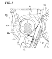
- FIG. 3 is a longitudinal cross-section view in which the cleaning unit 43e is enlarged.
- a cleaning blade 62 and the photoreceptor drum 43a are omitted in FIG. 2B . As shown in FIG.
- the cleaning unit 43e is disposed in the lateral side of the photoreceptor drum 43a, and includes a frame 61, a cleaning blade 62, a screw 63, and a toner crushing member 64. Moreover, among components of the cleaning unit 43e, the screw 63 and the toner crushing member 64 configures a waste toner transporting device (toner transporting device) of the present disclosure. That is, in the present embodiment, the function of the waste toner transporting device of the present disclosure is incorporated in the inner portion of the cleaning unit 43e.
- the inner portion of the frame 61 becomes the transportation path of the waste toner T, and the frame 61 is an approximately cylindrical container which accommodates the screw 63 and the toner crushing member 64 in the inner portion of the frame.
- an opening for introducing the waste toner T scraped from the photoreceptor drum 43a to the inner portion of the frame is provided in the side portion of the photoreceptor drum 43a side of the frame 61.
- Such a frame 61 is fixed to a rigid member which becomes the framework of the multifunction machine A.
- the cleaning blade 62 is disposed in the opening portion of the frame 61 so as to come into frictional contact with the circumferential surface of the photoreceptor drum 43a, and scrapes the residual toner which remains in the circumferential surface of the photoreceptor drum 43a.
- the screw 63 transports the residual toner scraped using the cleaning blade 62 up to the waste toner transport portion 45 as the waste toner T.
- the screw 63 includes a shaft portion 63a which is rotatably pivoted to the frame 61, and a spiral fin 63b which is wound around the shaft portion.
- the fin 63b is wound in the clockwise direction when viewed from the direction shown in FIG. 3 , and the screw 63 is rotated in the clockwise direction when viewed from the direction shown in FIG. 3 by a driving mechanism (not shown).
- a driving mechanism not shown
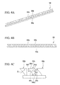
- FIGS. 4A to 4C are views showing the toner crushing member 64
- FIG. 4A is the perspective view thereof
- FIG. 4B is the front view thereof
- FIG. 4C is an enlarged view in which a portion of the toner crushing member 64 is enlarged.
- the toner crushing member 64 includes a long base portion 64a which extends in the axial direction of the screw 63 and a plurality of flexible plate members 64b which are disposed at equal intervals in the longitudinal direction of the base portion 64a.
- the toner crushing member 64 is disposed between the cleaning blade 62 and the screw 63, the flexible plate member 64b is deformed according to the movement of the fin 63b of the screw 63, and thereby, the accumulated waste toner T is crushed.
- the base portion 64a is bent in an L shape when viewed from the longitudinal direction and fixed to the frame 61.
- the base portion 64a is formed of polyethylene terephthalate (PET), and the base portion 64a is attached to the frame 61 using an adhesive.
- PET polyethylene terephthalate
- the flexible plate member 64b is a plate member having an approximately triangular shape which is pointed toward the upstream side in the waste toner transport direction (the transport direction of the waste toner T due to the screw 63), and the flexible plate member includes an inclined side 64c which is toward the base portion 64a side and an upper side 64d which is parallel with respect to the base portion 64a.
- the inclined side 64c is configured so as to be perpendicular in the extension direction X of the fin 63b so that the flexible plate member 64b is not rolled up in the fin 63b when the fin 63b is rotated.
- the flexible plate member 64b has a shape which spreads in the height direction (the direction perpendicular in the extension direction of the base portion 64a) from the upstream side toward the downstream side in the waste toner transport direction. Similar to the base portion 64a, the flexible plate member 64b is formed of polyethylene terephthalate (PET), and thereby, the flexible plate member 64b has flexibility. Moreover, other sheets made of resin such as Teflon (registered trademark) or Kapton (registered trademark) may be adopted as the material of the flexible plate member 64b, as long as they have flexibility. However, from the viewpoints of cost and durability, polyethylene terephthalate (PET) is more preferable.
- PET polyethylene terephthalate
- the downstream side end 64e in waste toner transport direction is fixed to the base portion 64a.
- the upstream side end 64f is separated from the base portion 64a, the downstream side end 64e is fixed to the base portion 64a, and thereby, the upstream side end is supported so as to be connected to the base portion 64a in a standing position.
- the flexible plate members 64b are arranged along the shaft portion 63a of the screw 63, and the upper portion of the flexible plate member 64b is disposed so as to bump into and contact the fin 63b.
- the placement pitch P1 of the flexible plate members 64b is set so as to be approximately 1 mm smaller than the helical pitch P2 of the fin 63b of the screw 63 (refer to FIGS. 5A to 5C ). That is, the placement pitch P1 of the flexible plate members 64b and the helical pitch P2 are different from each other. Also, the placement pitch P1 as used herein means the distance between the flexible plate members 64b which are disposed so as to be adjacent in the axial direction of the screw 63. In addition, the helical pitch P2 as used herein means the gap in which the first turned portion and the second turned portion (adjacent portions) of the fin 63b are separated from each other in the axial direction of the screw 63.
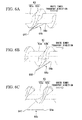
- FIGS. 5A to 5C are perspective views showing a portion of the screw 63 and the toner crushing member 64, and shows a time-sequential change state in the order of FIGS. 5A, 5B, and 5C .
- FIG. 5A shows a state where the fin 63b bumps into and contacts the upstream side ends 64f of the flexible plate members 64b.
- FIG. 5B shows a state where the fin 63b bumps into and contacts between the upstream side ends 64f and the downstream side ends 64e of the flexible plate members 64b.
- FIG. 5A shows a state where the fin 63b bumps into and contacts between the upstream side ends 64f and the downstream side ends 64e of the flexible plate members 64b.
- FIG. 5C shows a state where the fin 63b bumps into and contacts the downstream side ends 64e of the flexible plate members 64b.
- FIGS. 6A to 6C are plan views in which only one flexible plate member 64b shown in FIGS. 5A to 5C is enlarged, FIG. 6A corresponds to FIG. 5A , FIG. 6B corresponds to FIG. 5B , and FIG. 6C corresponds to FIG. 5C .
- the upstream side end 64f of the flexible plate member 64b greatly moves in the radial direction of the shaft portion 63a of the screw 63.
- the flexible plate member 64b is greatly inclined in the direction in which the upstream side is separated from the screw 63, and the flexible plate member 64b is twisted with the downstream side fixed to the base portion 64a as the supporting point.
- the flexible plate member 64b repeats the waving movement so as to flap from the upstream side toward the downstream side. In this way, the flexible plate member 64b repeats the waving movement so as to flap from the upstream side toward the downstream side, and thereby, the waste toner T is also moved from the upstream side to the downstream side due to the movement of the flexible plate member 64b.
- the rotating screw 63 transports the residual toner, which is scraped from the circumferential surface of the photoreceptor drum 43a by the cleaning blade 62, up to the waste toner transport portion 45. Moreover, in the cleaning unit 43e, due to the deformation of the flexible plate member 64b, the waste toner T which has accumulated around the screw 63 is crushed, and the waste toner T is transported toward the waste toner transport portion 45.
- the waste toner T is transported toward the downstream side by both the screw 63 and the toner crushing member 64. Therefore, the movement of the above flexible plate member 64b can supplement the decrease in the transportability of the waste toner T due to the placement of the toner crushing member 64. As a result, the transportability of the waste toner T is maintained well. Moreover, the waste toner T which is accumulated around the screw is crushed by the movement of flexible board member 64b being repeated. Therefore, according to the multifunction machine A of the present embodiment, the accumulated waste toner T can be crushed without requiring complicated mechanisms such as a striking mechanism or a decreasing of the transportability of the waste toner T.
- the plurality of flexible plate members 64b are provided along the shaft portion 63a of the screw 63. Therefore, while the accumulation of the waste toner T is crushed over the entire region in the longitudinal direction of the screw 63 by the flexible plate member 64, the waste toner T can be transported.
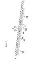
- the placement pitch P1 of the flexible plate members 64b and the helical pitch P2 are different from each other. Therefore, as shown in FIG. 7 , the timing of the deformation of the flexible plate member 64b is shifted in the longitudinal direction of the screw 63. That is, as shown in FIG. 7 , the plurality of installed flexible plate members 64b are deformed so as to wave. The load which the screw 63 receives from flexible plate members 64b is changed according to posture (inclination) of the flexible board member 64b.
- the plurality of flexible plate members 64b are deformed so as to wave, and thereby, all the postures of the flexible plate members 64b being the same can be avoided, the loads which receive from the flexible plate members 64b can be different from one another at every portion in the longitudinal direction of the screw 63. As a result, large load acting on the screw 63 at a time is prevented, and it is possible to prevent the screw 63 from being bent. Also, the above-mentioned wave advances towards the transport direction of the waste toner T. As a result, due to the advance of the wave, the waste toner T can be transported and the transportability of the waste toner T can be improved.
- the wave can be formed even when the placement pitch P1 of the flexible plate members 64b is greater than the helical pitch P2.
- the placement pitch P1 of the flexible plate members 64b be smaller than the helical pitch P2.
- the length in the height direction of the flexible plate member 64b increases from the upstream side toward the downstream side in the transport direction of the waste toner T. Therefore, as shown in FIG. 4C , a large interval can be formed between the inclined side 64c and the base portion 64a, and the waste toner T can be smoothly supplied from the cleaning blade 62 to the screw 63.
- the configuration is described in which the flexible plate member 64b has a triangular shape which spreads in the height direction from the upstream side toward the downstream side in the transport direction of the waste toner T.
- the present disclosure is not limited to the triangular shape, and as shown in FIG. 8A , a rectangular flexible plate member 64a can be used.
- a flexible plate member 64bb including an inclined side 64c1 which is toward the side opposite to the base portion 64a can be used.
- the base portion 64a of the toner crushing member 64 is fixed to the frame 61 in the rear side (screw side) of the installation location of the cleaning blade 62.
- the base portion 64a is formed of polyethylene terephthalate (PET), and the base portion 64a is attached to the frame 61 using adhesive.
- PET polyethylene terephthalate
- the base portion 64a biases the flexible plate member 64b toward the screw 63.
- the flexible plate member 64b is a plate member having an approximately triangular shape which is pointed toward the upstream side in the waste toner transport direction (the transport direction of the waste toner T due to the screw 63), and the flexible plate member includes the inclined side 64c which is toward the base portion 64a side and the upper side 64d which is parallel with respect to the base portion 64a.
- the inclined side 64c is configured so as to be perpendicular in the extension direction X of the fin 63b so that the flexible plate member 64b is not rolled up in the fin 63b when the fin 63b is rotated.
- the flexible plate member 64b has a shape in which the length in the height direction (the direction perpendicular in the extension direction of the base portion 64a) from the upstream side toward the downstream side in the waste toner transport direction increases.
- the width L1 of a tip portion 64b1 is larger than the width L2 of a root portion 64b2. That is, the present embodiment, the flexible board member 64b includes the root portion 64b2 which is fixed to the base portion 64a and the tip portion 64b1 in which the width is wider than that of the root portion 64b2 in the transport direction of the waste toner T in the screw 63.
- the flexible plate member 64b is formed of polyethylene terephthalate (PET), and thereby, the flexible plate member 64b has flexibility.
- other sheets made of resin such as Teflon (registered trademark) or Kapton (registered trademark) may be adopted as the material of the flexible plate member 64b, as long as they have flexibility.
- Teflon registered trademark
- Kapton registered trademark
- PET polyethylene terephthalate
- the downstream side end 64e in waste toner transport direction is fixed to the base portion 64a, the upstream side end 64f is separated from the base portion 64a, the downstream side end 64e is fixed to the base portion 64a, and thereby, the upstream side end is supported so as to be erected to the base portion 64a.
- the flexible plate members 64b are arranged along the shaft portion 63 a of the screw 63, and the tip portion 64b1 side is disposed so as to bump into and contact the fin 63b.
- the placement pitch P1 of the flexible plate members 64b is set so as to be approximately 1mm smaller than the helical pitch P2 of the fin 63b of the screw 63 (refer to FIGS. 5A to 5C ). That is, the placement pitch P1 of the flexible plate members 64b and the helical pitch P2 are different from each other.
- the placement pitch P1 as used herein means the distance between the flexible plate members 64b which are disposed so as to be adjacent in the axial direction of the screw 63.
- the helical pitch P2 as used herein means the gap in which the first turned portion and the second turned portion (adjacent portions) of the fin 63b are separated from each other in the axial direction of the screw 63.
- the flexible plate members 64b are fixed to the base portion 64a which extends along the shaft portion 63a of the screw 63, and the width of the root portion 64b2 of the flexible plate member 64b are set so as to be narrower than the width of the tip portion 64b1 in the transport direction of the toner T (the extension direction of the shaft portion 63a) in the screw 63.
- the toner T can be crushed over a wide range by the tip portion 64b 1.
- a wide space through which the toner T can pass can be secured around the root portion 64b2, the toner can be smoothly supplied to the screw 63. Therefore, according to the present embodiment, the accumulated toner T can be crushed over a wide range while the decrease in the transportability of the toner T is suppressed.
- the plurality of flexible plate members 64b are provided while being separated from one another along the shaft portion 63a of the screw 63. Therefore, accumulation of the waste toner T can be crushed over the entire region in the longitudinal direction of the screw 63 by the flexible plate member 64.
- the base portion 64a biases the flexible plate member 64b toward the screw 63.
- the locations of the flexible plate member 64b within one-third from the tip in the height direction contact the fin 63b of the screw 63.
- the location of 3 mm from the tip of the flexible plate member 64b is set so as to bump into and contact the fin 63b.
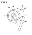
- a distance d1 from the tip B of the cleaning blade 62 to the flexible plate member 64b be shorter than one-third of a distance d2 from the tip B of the cleaning blade 62 to the intersection of the line segment BC and the tip D of the fin 63b. Therefore, the bending of the flexible plate member 64b when the flexible plate member bumps into and contact the fin 63b can be sufficiently increased, and the impact force which is applied to the toner T when the flexible plate member 64b is restored to the original shape can be sufficiently increased.
- the flexible plate member 64b has a shape which spreads in the height direction from the upstream side toward the downstream side. As shown in FIG. 4C , a large interval can be formed between the inclined side 64c and the base portion 64a. Accordingly, the waste toner T can be smoothly supplied from the cleaning blade 62 to the screw 63.
- the configuration is described in which the flexible plate member 64b has a triangular shape which spreads in the height direction from the upstream side toward the downstream side in the transport direction of the waste toner T.
- the flexible board member 64b in the present disclosure is not limited to such a shape.
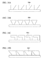
- FIGS. 10A to 10D other shapes can be adopted if the width of the tip portion is wider than the width of the root portion.
- FIG. 10A shows a flexible plate member 64bc which has a triangular shape which spreads in the height direction from the downstream side toward the upstream side.
- FIG. 10B shows a flexible plate member 64bd which has an approximately inverted triangular shape.
- FIG. 10C shows a flexible plate member 64be which is formed in a rectangular shape in which the widths of the tip portion and the root portion are different from each other.
- FIG. 10D shows a flexible plate member 64bf which has a shape in which the upper edge of the downstream side of the flexible plate member 64b of the embodiment is cut.
- the configuration in which the image forming apparatus of the present disclosure is applied to the multifunction machine A for color printing is described.
- the disclosure is not limited thereto, and the present disclosure may be applied to a printer, a facsimile device, or a multifunction machine for monochromatic printing.
- the configuration in which the toner transporting device of the present disclosure is incorporated in the inner portion of the cleaning unit 43e as the waste toner transporting device is described.
- the present disclosure may be incorporated not only as the waste toner transporting device but also in a toner transporting device for transporting the toner to the developing unit 43d or a toner transporting device for transporting the toner to a toner container (not shown) which accommodates the toner supplied to the developing unit 43d.
- a toner transporting device for transporting the toner to the developing unit 43d or a toner transporting device for transporting the toner to a toner container (not shown) which accommodates the toner supplied to the developing unit 43d.
Landscapes
- Life Sciences & Earth Sciences (AREA)
- Engineering & Computer Science (AREA)
- Environmental & Geological Engineering (AREA)
- Sustainable Development (AREA)
- Physics & Mathematics (AREA)
- General Physics & Mathematics (AREA)
- Cleaning In Electrography (AREA)
Applications Claiming Priority (2)
| Application Number | Priority Date | Filing Date | Title |
|---|---|---|---|
| JP2011236010A JP5492860B2 (ja) | 2011-10-27 | 2011-10-27 | トナー搬送装置及びこれを備える画像形成装置 |
| JP2011259212A JP2013113987A (ja) | 2011-11-28 | 2011-11-28 | トナー搬送装置及びこれを備える画像形成装置 |
Publications (2)
| Publication Number | Publication Date |
|---|---|
| EP2587318A1 true EP2587318A1 (de) | 2013-05-01 |
| EP2587318B1 EP2587318B1 (de) | 2021-03-17 |
Family
ID=47191518
Family Applications (1)
| Application Number | Title | Priority Date | Filing Date |
|---|---|---|---|
| EP12189702.9A Not-in-force EP2587318B1 (de) | 2011-10-27 | 2012-10-24 | Tonerfördervorrichtung und Bilderzeugungsvorrichtung mit der Tonerfördervorrichtung |
Country Status (4)
| Country | Link |
|---|---|
| US (1) | US8862043B2 (de) |
| EP (1) | EP2587318B1 (de) |
| KR (1) | KR101434748B1 (de) |
| CN (1) | CN103092044B (de) |
Cited By (3)
| Publication number | Priority date | Publication date | Assignee | Title |
|---|---|---|---|---|
| JP2014235221A (ja) * | 2013-05-31 | 2014-12-15 | シャープ株式会社 | クリーニング装置およびこれを用いる画像形成装置 |
| EP2846200A1 (de) * | 2013-09-10 | 2015-03-11 | Kyocera Document Solutions Inc. | Reinigungsvorrichtung, Bilderzeugungsvorrichtung und Tonerbrechelement |
| EP2950161A1 (de) * | 2014-05-27 | 2015-12-02 | KYOCERA Document Solutions Inc. | Reinigungsvorrichtung |
Families Citing this family (9)
| Publication number | Priority date | Publication date | Assignee | Title |
|---|---|---|---|---|
| JP2017097054A (ja) * | 2015-11-19 | 2017-06-01 | 京セラドキュメントソリューションズ株式会社 | 画像形成装置 |
| JP6638495B2 (ja) * | 2016-03-18 | 2020-01-29 | 株式会社リコー | クリーニング装置、プロセスユニット及び画像形成装置 |
| JP6432555B2 (ja) * | 2016-04-06 | 2018-12-05 | 京セラドキュメントソリューションズ株式会社 | クリーニング装置およびそれを備えた画像形成装置 |
| JP6551308B2 (ja) | 2016-05-31 | 2019-07-31 | 京セラドキュメントソリューションズ株式会社 | クリーニング装置及び画像形成装置 |
| JP6500856B2 (ja) * | 2016-07-28 | 2019-04-17 | 京セラドキュメントソリューションズ株式会社 | クリーニング装置及び画像形成装置 |
| JP2019184697A (ja) * | 2018-04-04 | 2019-10-24 | シャープ株式会社 | トナー排出装置、画像形成装置及び複合機並びにトナー排出方法 |
| US11300901B2 (en) | 2019-11-15 | 2022-04-12 | Canon Kabushiki Kaisha | Toner conveying apparatus having orthogonal toner conveying paths and image forming apparatus |
| JP7465437B2 (ja) * | 2020-01-29 | 2024-04-11 | 株式会社リコー | クリーニング装置、プロセスカートリッジ、及び、画像形成装置 |
| JP2024047434A (ja) * | 2022-09-26 | 2024-04-05 | 富士フイルムビジネスイノベーション株式会社 | 掻取装置、及び画像形成装置 |
Citations (4)
| Publication number | Priority date | Publication date | Assignee | Title |
|---|---|---|---|---|
| JPS63174366U (de) * | 1987-02-24 | 1988-11-11 | ||
| JP2000181315A (ja) * | 1998-12-15 | 2000-06-30 | Matsushita Graphic Communication Systems Inc | クリーニング装置およびそれに用いる現像剤ほぐし部材 |
| JP2009109830A (ja) * | 2007-10-31 | 2009-05-21 | Sharp Corp | クリーニング装置 |
| US20100028051A1 (en) * | 2008-07-30 | 2010-02-04 | Kyocera Mita Corporation | Toner transferring mechanism, developing apparatus and image forming apparatus therewith |
Family Cites Families (11)
| Publication number | Priority date | Publication date | Assignee | Title |
|---|---|---|---|---|
| JPS6159469A (ja) * | 1984-08-31 | 1986-03-26 | Fuji Xerox Co Ltd | 電子写真複写機のクリ−ニング装置 |
| JPS63174366A (ja) | 1987-01-14 | 1988-07-18 | Fujitsu Ltd | 半導体装置の製造方法 |
| US5510881A (en) * | 1994-11-18 | 1996-04-23 | Xerox Corporation | Positive push development auger |
| JPH11327397A (ja) | 1998-05-11 | 1999-11-26 | Canon Inc | 画像形成装置 |
| JP2007249123A (ja) | 2006-03-20 | 2007-09-27 | Konica Minolta Business Technologies Inc | 現像剤搬送装置及びそれを装着した画像形成装置 |
| JP4353236B2 (ja) * | 2006-11-13 | 2009-10-28 | 富士ゼロックス株式会社 | 画像形成装置 |
| JP2008158170A (ja) | 2006-12-22 | 2008-07-10 | Kyocera Mita Corp | クリーニング装置及びそれを備えた画像形成装置 |
| JP2008158168A (ja) * | 2006-12-22 | 2008-07-10 | Kyocera Mita Corp | クリーニング装置及びそれを備えた画像形成装置 |
| JP5155982B2 (ja) | 2009-10-28 | 2013-03-06 | 京セラドキュメントソリューションズ株式会社 | クリーニング装置及びこれを備えた画像形成装置 |
| JP5630167B2 (ja) * | 2010-09-09 | 2014-11-26 | 富士ゼロックス株式会社 | 清掃装置及びこれを用いた画像形成組立体、画像形成装置 |
| US8989632B2 (en) * | 2012-04-04 | 2015-03-24 | Lexmark International, Inc. | Toner anti-bridging agitator for an image forming device |
-
2012
- 2012-10-24 EP EP12189702.9A patent/EP2587318B1/de not_active Not-in-force
- 2012-10-25 KR KR1020120119005A patent/KR101434748B1/ko not_active Expired - Fee Related
- 2012-10-25 US US13/660,118 patent/US8862043B2/en active Active
- 2012-10-29 CN CN201210431480.8A patent/CN103092044B/zh not_active Expired - Fee Related
Patent Citations (4)
| Publication number | Priority date | Publication date | Assignee | Title |
|---|---|---|---|---|
| JPS63174366U (de) * | 1987-02-24 | 1988-11-11 | ||
| JP2000181315A (ja) * | 1998-12-15 | 2000-06-30 | Matsushita Graphic Communication Systems Inc | クリーニング装置およびそれに用いる現像剤ほぐし部材 |
| JP2009109830A (ja) * | 2007-10-31 | 2009-05-21 | Sharp Corp | クリーニング装置 |
| US20100028051A1 (en) * | 2008-07-30 | 2010-02-04 | Kyocera Mita Corporation | Toner transferring mechanism, developing apparatus and image forming apparatus therewith |
Cited By (3)
| Publication number | Priority date | Publication date | Assignee | Title |
|---|---|---|---|---|
| JP2014235221A (ja) * | 2013-05-31 | 2014-12-15 | シャープ株式会社 | クリーニング装置およびこれを用いる画像形成装置 |
| EP2846200A1 (de) * | 2013-09-10 | 2015-03-11 | Kyocera Document Solutions Inc. | Reinigungsvorrichtung, Bilderzeugungsvorrichtung und Tonerbrechelement |
| EP2950161A1 (de) * | 2014-05-27 | 2015-12-02 | KYOCERA Document Solutions Inc. | Reinigungsvorrichtung |
Also Published As
| Publication number | Publication date |
|---|---|
| US8862043B2 (en) | 2014-10-14 |
| KR101434748B1 (ko) | 2014-08-26 |
| KR20130046368A (ko) | 2013-05-07 |
| CN103092044A (zh) | 2013-05-08 |
| EP2587318B1 (de) | 2021-03-17 |
| US20130108341A1 (en) | 2013-05-02 |
| CN103092044B (zh) | 2015-12-16 |
Similar Documents
| Publication | Publication Date | Title |
|---|---|---|
| EP2587318B1 (de) | Tonerfördervorrichtung und Bilderzeugungsvorrichtung mit der Tonerfördervorrichtung | |
| JP5492860B2 (ja) | トナー搬送装置及びこれを備える画像形成装置 | |
| JP5983686B2 (ja) | 用紙搬送装置及び画像形成装置 | |
| CN101713955B (zh) | 图像形成装置及废弃粉末传送方法 | |
| US9229410B2 (en) | Sheet curl correction apparatus and image forming apparatus | |
| US20110062651A1 (en) | Image forming apparatus | |
| US20190039844A1 (en) | Paper feeding device, image forming apparatus and paper feeding method | |
| US8942607B2 (en) | Guide device with mechanism capable of minimizing damage to toner image by water droplet and image forming apparatus incorporating same | |
| EP2019341A1 (de) | Bilderzeugungsvorrichtung | |
| JP2013113987A (ja) | トナー搬送装置及びこれを備える画像形成装置 | |
| US10401752B2 (en) | Image forming apparatus | |
| US6002906A (en) | Image forming apparatus which controls the image forming operation on the basis of the recording sheet | |
| US20110188872A1 (en) | Fixing device and image forming apparatus | |
| US8302953B2 (en) | Image forming apparatus | |
| US20180237240A1 (en) | Image forming apparatus and image forming method | |
| US9819827B2 (en) | Image forming apparatus | |
| JP2004361752A (ja) | 画像形成装置 | |
| US20100310277A1 (en) | Toner cartridge and image forming apparatus | |
| CN111453477A (zh) | 纸张搬送机构以及图像形成装置 | |
| US10046933B2 (en) | Image forming apparatus | |
| JP2011137981A (ja) | トナー搬送装置及び画像形成装置 | |
| US20260019517A1 (en) | Document conveyance apparatus, image reading apparatus, and image forming apparatus | |
| CN104181790A (zh) | 打印装置及打印装置的控制方法 | |
| JP6302631B2 (ja) | 画像形成装置 | |
| JP7392504B2 (ja) | 画像形成装置 |
Legal Events
| Date | Code | Title | Description |
|---|---|---|---|
| PUAI | Public reference made under article 153(3) epc to a published international application that has entered the european phase |
Free format text: ORIGINAL CODE: 0009012 |
|
| AK | Designated contracting states |
Kind code of ref document: A1 Designated state(s): AL AT BE BG CH CY CZ DE DK EE ES FI FR GB GR HR HU IE IS IT LI LT LU LV MC MK MT NL NO PL PT RO RS SE SI SK SM TR |
|
| AX | Request for extension of the european patent |
Extension state: BA ME |
|
| 17P | Request for examination filed |
Effective date: 20130827 |
|
| RBV | Designated contracting states (corrected) |
Designated state(s): AL AT BE BG CH CY CZ DE DK EE ES FI FR GB GR HR HU IE IS IT LI LT LU LV MC MK MT NL NO PL PT RO RS SE SI SK SM TR |
|
| STAA | Information on the status of an ep patent application or granted ep patent |
Free format text: STATUS: EXAMINATION IS IN PROGRESS |
|
| 17Q | First examination report despatched |
Effective date: 20181019 |
|
| GRAP | Despatch of communication of intention to grant a patent |
Free format text: ORIGINAL CODE: EPIDOSNIGR1 |
|
| STAA | Information on the status of an ep patent application or granted ep patent |
Free format text: STATUS: GRANT OF PATENT IS INTENDED |
|
| INTG | Intention to grant announced |
Effective date: 20201123 |
|
| GRAS | Grant fee paid |
Free format text: ORIGINAL CODE: EPIDOSNIGR3 |
|
| GRAA | (expected) grant |
Free format text: ORIGINAL CODE: 0009210 |
|
| STAA | Information on the status of an ep patent application or granted ep patent |
Free format text: STATUS: THE PATENT HAS BEEN GRANTED |
|
| AK | Designated contracting states |
Kind code of ref document: B1 Designated state(s): AL AT BE BG CH CY CZ DE DK EE ES FI FR GB GR HR HU IE IS IT LI LT LU LV MC MK MT NL NO PL PT RO RS SE SI SK SM TR |
|
| REG | Reference to a national code |
Ref country code: GB Ref legal event code: FG4D |
|
| REG | Reference to a national code |
Ref country code: CH Ref legal event code: EP |
|
| REG | Reference to a national code |
Ref country code: DE Ref legal event code: R096 Ref document number: 602012074807 Country of ref document: DE |
|
| REG | Reference to a national code |
Ref country code: IE Ref legal event code: FG4D |
|
| REG | Reference to a national code |
Ref country code: AT Ref legal event code: REF Ref document number: 1372804 Country of ref document: AT Kind code of ref document: T Effective date: 20210415 |
|
| REG | Reference to a national code |
Ref country code: LT Ref legal event code: MG9D |
|
| PG25 | Lapsed in a contracting state [announced via postgrant information from national office to epo] |
Ref country code: NO Free format text: LAPSE BECAUSE OF FAILURE TO SUBMIT A TRANSLATION OF THE DESCRIPTION OR TO PAY THE FEE WITHIN THE PRESCRIBED TIME-LIMIT Effective date: 20210617 Ref country code: BG Free format text: LAPSE BECAUSE OF FAILURE TO SUBMIT A TRANSLATION OF THE DESCRIPTION OR TO PAY THE FEE WITHIN THE PRESCRIBED TIME-LIMIT Effective date: 20210617 Ref country code: HR Free format text: LAPSE BECAUSE OF FAILURE TO SUBMIT A TRANSLATION OF THE DESCRIPTION OR TO PAY THE FEE WITHIN THE PRESCRIBED TIME-LIMIT Effective date: 20210317 Ref country code: GR Free format text: LAPSE BECAUSE OF FAILURE TO SUBMIT A TRANSLATION OF THE DESCRIPTION OR TO PAY THE FEE WITHIN THE PRESCRIBED TIME-LIMIT Effective date: 20210618 Ref country code: FI Free format text: LAPSE BECAUSE OF FAILURE TO SUBMIT A TRANSLATION OF THE DESCRIPTION OR TO PAY THE FEE WITHIN THE PRESCRIBED TIME-LIMIT Effective date: 20210317 |
|
| REG | Reference to a national code |
Ref country code: AT Ref legal event code: MK05 Ref document number: 1372804 Country of ref document: AT Kind code of ref document: T Effective date: 20210317 |
|
| REG | Reference to a national code |
Ref country code: NL Ref legal event code: MP Effective date: 20210317 |
|
| PG25 | Lapsed in a contracting state [announced via postgrant information from national office to epo] |
Ref country code: LV Free format text: LAPSE BECAUSE OF FAILURE TO SUBMIT A TRANSLATION OF THE DESCRIPTION OR TO PAY THE FEE WITHIN THE PRESCRIBED TIME-LIMIT Effective date: 20210317 Ref country code: RS Free format text: LAPSE BECAUSE OF FAILURE TO SUBMIT A TRANSLATION OF THE DESCRIPTION OR TO PAY THE FEE WITHIN THE PRESCRIBED TIME-LIMIT Effective date: 20210317 Ref country code: SE Free format text: LAPSE BECAUSE OF FAILURE TO SUBMIT A TRANSLATION OF THE DESCRIPTION OR TO PAY THE FEE WITHIN THE PRESCRIBED TIME-LIMIT Effective date: 20210317 |
|
| PG25 | Lapsed in a contracting state [announced via postgrant information from national office to epo] |
Ref country code: NL Free format text: LAPSE BECAUSE OF FAILURE TO SUBMIT A TRANSLATION OF THE DESCRIPTION OR TO PAY THE FEE WITHIN THE PRESCRIBED TIME-LIMIT Effective date: 20210317 |
|
| PG25 | Lapsed in a contracting state [announced via postgrant information from national office to epo] |
Ref country code: LT Free format text: LAPSE BECAUSE OF FAILURE TO SUBMIT A TRANSLATION OF THE DESCRIPTION OR TO PAY THE FEE WITHIN THE PRESCRIBED TIME-LIMIT Effective date: 20210317 Ref country code: CZ Free format text: LAPSE BECAUSE OF FAILURE TO SUBMIT A TRANSLATION OF THE DESCRIPTION OR TO PAY THE FEE WITHIN THE PRESCRIBED TIME-LIMIT Effective date: 20210317 Ref country code: EE Free format text: LAPSE BECAUSE OF FAILURE TO SUBMIT A TRANSLATION OF THE DESCRIPTION OR TO PAY THE FEE WITHIN THE PRESCRIBED TIME-LIMIT Effective date: 20210317 Ref country code: AT Free format text: LAPSE BECAUSE OF FAILURE TO SUBMIT A TRANSLATION OF THE DESCRIPTION OR TO PAY THE FEE WITHIN THE PRESCRIBED TIME-LIMIT Effective date: 20210317 Ref country code: SM Free format text: LAPSE BECAUSE OF FAILURE TO SUBMIT A TRANSLATION OF THE DESCRIPTION OR TO PAY THE FEE WITHIN THE PRESCRIBED TIME-LIMIT Effective date: 20210317 |
|
| PG25 | Lapsed in a contracting state [announced via postgrant information from national office to epo] |
Ref country code: IS Free format text: LAPSE BECAUSE OF FAILURE TO SUBMIT A TRANSLATION OF THE DESCRIPTION OR TO PAY THE FEE WITHIN THE PRESCRIBED TIME-LIMIT Effective date: 20210717 Ref country code: RO Free format text: LAPSE BECAUSE OF FAILURE TO SUBMIT A TRANSLATION OF THE DESCRIPTION OR TO PAY THE FEE WITHIN THE PRESCRIBED TIME-LIMIT Effective date: 20210317 Ref country code: PT Free format text: LAPSE BECAUSE OF FAILURE TO SUBMIT A TRANSLATION OF THE DESCRIPTION OR TO PAY THE FEE WITHIN THE PRESCRIBED TIME-LIMIT Effective date: 20210719 Ref country code: PL Free format text: LAPSE BECAUSE OF FAILURE TO SUBMIT A TRANSLATION OF THE DESCRIPTION OR TO PAY THE FEE WITHIN THE PRESCRIBED TIME-LIMIT Effective date: 20210317 Ref country code: ES Free format text: LAPSE BECAUSE OF FAILURE TO SUBMIT A TRANSLATION OF THE DESCRIPTION OR TO PAY THE FEE WITHIN THE PRESCRIBED TIME-LIMIT Effective date: 20210317 Ref country code: SK Free format text: LAPSE BECAUSE OF FAILURE TO SUBMIT A TRANSLATION OF THE DESCRIPTION OR TO PAY THE FEE WITHIN THE PRESCRIBED TIME-LIMIT Effective date: 20210317 |
|
| REG | Reference to a national code |
Ref country code: DE Ref legal event code: R097 Ref document number: 602012074807 Country of ref document: DE |
|
| PLBE | No opposition filed within time limit |
Free format text: ORIGINAL CODE: 0009261 |
|
| STAA | Information on the status of an ep patent application or granted ep patent |
Free format text: STATUS: NO OPPOSITION FILED WITHIN TIME LIMIT |
|
| PG25 | Lapsed in a contracting state [announced via postgrant information from national office to epo] |
Ref country code: DK Free format text: LAPSE BECAUSE OF FAILURE TO SUBMIT A TRANSLATION OF THE DESCRIPTION OR TO PAY THE FEE WITHIN THE PRESCRIBED TIME-LIMIT Effective date: 20210317 Ref country code: AL Free format text: LAPSE BECAUSE OF FAILURE TO SUBMIT A TRANSLATION OF THE DESCRIPTION OR TO PAY THE FEE WITHIN THE PRESCRIBED TIME-LIMIT Effective date: 20210317 |
|
| PGFP | Annual fee paid to national office [announced via postgrant information from national office to epo] |
Ref country code: DE Payment date: 20210914 Year of fee payment: 10 |
|
| 26N | No opposition filed |
Effective date: 20211220 |
|
| PG25 | Lapsed in a contracting state [announced via postgrant information from national office to epo] |
Ref country code: SI Free format text: LAPSE BECAUSE OF FAILURE TO SUBMIT A TRANSLATION OF THE DESCRIPTION OR TO PAY THE FEE WITHIN THE PRESCRIBED TIME-LIMIT Effective date: 20210317 |
|
| PG25 | Lapsed in a contracting state [announced via postgrant information from national office to epo] |
Ref country code: IT Free format text: LAPSE BECAUSE OF FAILURE TO SUBMIT A TRANSLATION OF THE DESCRIPTION OR TO PAY THE FEE WITHIN THE PRESCRIBED TIME-LIMIT Effective date: 20210317 |
|
| PG25 | Lapsed in a contracting state [announced via postgrant information from national office to epo] |
Ref country code: IS Free format text: LAPSE BECAUSE OF FAILURE TO SUBMIT A TRANSLATION OF THE DESCRIPTION OR TO PAY THE FEE WITHIN THE PRESCRIBED TIME-LIMIT Effective date: 20210717 |
|
| REG | Reference to a national code |
Ref country code: CH Ref legal event code: PL |
|
| REG | Reference to a national code |
Ref country code: BE Ref legal event code: MM Effective date: 20211031 |
|
| GBPC | Gb: european patent ceased through non-payment of renewal fee |
Effective date: 20211024 |
|
| PG25 | Lapsed in a contracting state [announced via postgrant information from national office to epo] |
Ref country code: MC Free format text: LAPSE BECAUSE OF FAILURE TO SUBMIT A TRANSLATION OF THE DESCRIPTION OR TO PAY THE FEE WITHIN THE PRESCRIBED TIME-LIMIT Effective date: 20210317 |
|
| PG25 | Lapsed in a contracting state [announced via postgrant information from national office to epo] |
Ref country code: LU Free format text: LAPSE BECAUSE OF NON-PAYMENT OF DUE FEES Effective date: 20211024 Ref country code: GB Free format text: LAPSE BECAUSE OF NON-PAYMENT OF DUE FEES Effective date: 20211024 Ref country code: BE Free format text: LAPSE BECAUSE OF NON-PAYMENT OF DUE FEES Effective date: 20211031 |
|
| PG25 | Lapsed in a contracting state [announced via postgrant information from national office to epo] |
Ref country code: LI Free format text: LAPSE BECAUSE OF NON-PAYMENT OF DUE FEES Effective date: 20211031 Ref country code: CH Free format text: LAPSE BECAUSE OF NON-PAYMENT OF DUE FEES Effective date: 20211031 |
|
| PG25 | Lapsed in a contracting state [announced via postgrant information from national office to epo] |
Ref country code: FR Free format text: LAPSE BECAUSE OF NON-PAYMENT OF DUE FEES Effective date: 20211031 |
|
| PG25 | Lapsed in a contracting state [announced via postgrant information from national office to epo] |
Ref country code: IE Free format text: LAPSE BECAUSE OF NON-PAYMENT OF DUE FEES Effective date: 20211024 |
|
| REG | Reference to a national code |
Ref country code: DE Ref legal event code: R119 Ref document number: 602012074807 Country of ref document: DE |
|
| PG25 | Lapsed in a contracting state [announced via postgrant information from national office to epo] |
Ref country code: HU Free format text: LAPSE BECAUSE OF FAILURE TO SUBMIT A TRANSLATION OF THE DESCRIPTION OR TO PAY THE FEE WITHIN THE PRESCRIBED TIME-LIMIT; INVALID AB INITIO Effective date: 20121024 Ref country code: CY Free format text: LAPSE BECAUSE OF FAILURE TO SUBMIT A TRANSLATION OF THE DESCRIPTION OR TO PAY THE FEE WITHIN THE PRESCRIBED TIME-LIMIT Effective date: 20210317 |
|
| PG25 | Lapsed in a contracting state [announced via postgrant information from national office to epo] |
Ref country code: DE Free format text: LAPSE BECAUSE OF NON-PAYMENT OF DUE FEES Effective date: 20230503 |
|
| PG25 | Lapsed in a contracting state [announced via postgrant information from national office to epo] |
Ref country code: MK Free format text: LAPSE BECAUSE OF FAILURE TO SUBMIT A TRANSLATION OF THE DESCRIPTION OR TO PAY THE FEE WITHIN THE PRESCRIBED TIME-LIMIT Effective date: 20210317 |
|
| PG25 | Lapsed in a contracting state [announced via postgrant information from national office to epo] |
Ref country code: TR Free format text: LAPSE BECAUSE OF FAILURE TO SUBMIT A TRANSLATION OF THE DESCRIPTION OR TO PAY THE FEE WITHIN THE PRESCRIBED TIME-LIMIT Effective date: 20210317 |
|
| PG25 | Lapsed in a contracting state [announced via postgrant information from national office to epo] |
Ref country code: MT Free format text: LAPSE BECAUSE OF FAILURE TO SUBMIT A TRANSLATION OF THE DESCRIPTION OR TO PAY THE FEE WITHIN THE PRESCRIBED TIME-LIMIT Effective date: 20210317 |